1
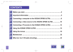
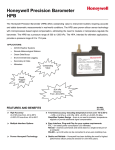
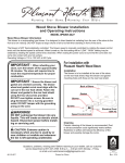
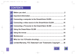
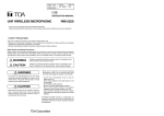
User’s
Manual
Models FP201/FP201A
High Accurate Pressure Sensor
Yokogawa Electric Corporation
Field Instruments Business Division
2-9-32, Naka-cho Musashino-shi, Tokyo 180-8750 Japan
Phone: 81-422-52-6077 Facsimile: 81-422-52-4892
Please read through this User's Manual before use for correct handling.
Please keep this User's Manual for future reference.
For safety:
The following symbol is used on the product and in this manual to ensure safe use:
indicates caution. This symbol is displayed on the product when it is necessary to refer to the User's Manual for
information on personnel and instrument safety. This symbol is displayed in the User's Manual to indicate precautions
for avoiding danger to the operator, such as an electric shock.
The following symbol is used only in this manual:
NOTE draws attention to essential information for understanding the operations and/or functions of the product.
1st Edition : Jul. 2002 (MC)
All Rights Reserved, Copyright © 2002, Yokogawa M&C Corporation
IM 01C10B11-01E
3rd Edition: Nov. 2004 (YK)
Yokogawa Electric Corporation
3.1 Specifications
The FP201/FP201A pressure sensors are shipped only after stringent inspection at the factory. Upon delivery, check the sensor according to the instructions given below.
(1) Visually check the sensor to ensure that it is free from damage.
(2) The model and suffix codes and the pressure range are indicated on the data plate
attached to the sensor. Cross-check this information with that in Table 2, "Model and
Suffix Codes" to ensure that the sensor is as specified in the order.
Note: If the specifications of the ordered sensor are not standard, refer to the label tag attached to the sensor.
2. HANDLING PRECAUTIONS
2.1 Storage
(1) Store the sensor in a location that meets the following requirements.
• No exposure to rain or water
• No major mechanical vibration or shocks
• Humidity and temperature within the following ranges—preferably as close as possible
to the normal condition (25°C, 65% RH)
Seal diaphragm
Temperature: 20 to 80°C; humidity: 5 to 95% RH
(non-condensing)
• No corrosive gases
(2) Whenever possible, store the sensor in the same
packaging that it was shipped in by the manufacturer.
(3) If the sensor has been put into use and the pressuresensing chamber contains fluids, clean the chamber
thoroughly before storing the sensor.
Syringe
Even when cleaning the sensor, exercise care to avoid
damaging the seal diaphragms.
Figure 1 Cleaning of the Pressuresensing Chamber Interior
2.2 Installation Location
CAUTION
Never use the sensor in an environment containing any explosive gas. It is not designed to be explosionproof.
Although the FP201/FP201A pressure sensors are designed for use in severe environment,
the following precautions should be observed to ensure that the sensors are used safely and
that they achieve the required accuracy for a prolonged period.
(1) If it is likely that the sensor will be exposed to direct sunlight and/or other radiated heat,
prepare some kind of heat insulation for the sensor.
(2) Avoid installing the sensor in an environment containing any corrosive gas.
(3) Although the sensor is designed to be water-resistant, avoid installing it in a location
exposed to splashes of rain.
(4) Although the sensor is durable for vibration, install it in a location where mechanical
vibration and/or shocks are minimal.
2.3 Precautions to Avoid Damaging the Sensor
(1) When measuring pressure or cleaning the sensor, exercise care to avoid damaging the
seal diaphragms (see Section 3.3, "Components").
(2) The seal diaphragm may be damaged if the measured fluid
within the pressure-sensing chamber freezes. If it is likely to
occur, prepare some kind of heat insulation etc. to avoid
measured fluid from freezing.
(3) When measuring liquid pressure (especially in vacuum or
high pressure condition), sudden pressure change causes
impulse pressure. Mount a damper (a fitting for dampening
Pressure damper
the pulsating pressure) or the like to keep the pressure
Figure
2
within the maximum allowable pressure (see Table 1).
2.4 Insulation Resistance and Withstanding Voltage Test Procedures
CAUTION
Carry out these tests only when absolutely necessary. Mistake in testing may result in electric shock to
the operator or damaging the sensor.
(1) Short-circuit the and lead wires. For each test, apply the following voltages across
the lead wires and the ground lead wire.
• Insulation Resistance Test: 500 V DC, for 2 minutes max.
Make sure the insulation resistance is 20 M or more.
• Withstanding Voltage Test: 500 V AC, for 1 minute max.
Make sure the leak current is 1 mA or less.
(2) After the tests, connect a 100 k resistor across the short-circuited two lead wires and the
ground lead wire in order to discharge any internal charge.
3. PRODUCT OVERVIEW
The FP201/FP201A pressure sensors can be used to measure gauge or absolute pressure
and output a 4 to 20 mA DC current signal corresponding to the measured pressure. The
FP201/FP201A can measure gas and liquid pressures directly with high accuracy and performance (e.g. temperature effects), along with long-term stability.
Table 1 Measuring Range
Code
J
N
M
T
S
K
L
A
B
C
D
E
F
G
H
Range in Pa
100k to 0
100k to 100k
100k to 300k
0 to 10k
0 to 20k
0 to 50k (abs)
0 to 100k (abs)
0 to 200k (abs)
0 to 500k (abs)
0 to 1M (abs)
0 to 2M (abs)
0 to 5M (abs)
0 to 10M
0 to 20M
0 to 35M
Maximum Allowable Pressure
200 kPa
400 kPa
800 kPa
50 kPa
100 kPa
100 kPa
200 kPa
400 kPa
1 MPa
2 MPa
4 MPa
10 MPa
20 MPa
40 MPa
50 MPa
<Supply voltage and Load Resistance>
1500
Load resistance (Ω)
1. PRODUCT INSPECTION
Operating
range
800
700
600
12
24 28
Supply voltage (V DC)
42
Load
resistance (Ω) = Supply voltage to be used (V)12 (V)
0.02 (A)
*The FP201A absolute-pressure sensor has only
seven measuring ranges: 50 kPa abs, 100 kPa abs,
200 kPa abs, 500 kPa abs, 1 MPa abs, 2 MPa abs,
and 5 MPa abs.
Measurement accuracy(Note 1)(Note 5): 0.25% of span (including linearity, hysteresis and repeatability)
10 kPa range:0.5% of span (including linearity, hysteresis and repeatability)
20 kPa range:0.35% of span (including linearity, hysteresis and repeatability)
Process connection R1:0.3% of span (including linearity, hysteresis and repeatability)
Temperature effect (zero point) [% of span/°C](Note 4): 0.02 for the range of 200 kPa or
more, 0.05 for the range of 100 kPa or 100 kPa, 0.03 for
the range of 100 k to 100 kPa or –100 k to 300 kPa, 0.08 for
the range of 20 kPa or 50 kPa, or 0.1 for the range of 10 kPa
Compensation temperature range(Note 4): 25 to 75°C, 10 to 75°C for the range of 10 kPa or 20
kP, 0 to 60°C (Process connection R1; 50 kPa (abs), 100 kPa (abs)),
0 to 75°C (Process connection R1; other ranges except for the above)
Operating temperature range: 40 to 80°C(Note 2)
Supply voltage effect (zero point): 0.005% of span/V
Attitude error:
Approx. 30 Pa/90°(Measuring range30 kPa), approx. 60 Pa/90°
(Measuring range30 kPa), approx. 400 Pa/90°(Process connection R1)
Output signal:
4 to 20 mA DC, two-wire
Measured fluid:
Liquid or gas
Vacuum pressure:
2.7 kPa abs or more; Note that negative pressure must not be
applied when the range is 50 kPa (gauge pressure) or less.
Supply voltage:
12 to 28 V DC (recommended voltage: 24 V DC10%) See Graph above.
Load resistance:
0 to 600 (at 24 V DC power supply) See Graph above.
Process connection:
G1/4, 3/8, 1/2 (PF1/4, 3/8, 1/2), or R1/4, 3/8, 1/2, 1 (PT1/4, 3/8, 1/2, 1)
Material:
Diaphragm: Hastelloy-C; nipple connector: SUS316 ; fill fluid:
silicone oil; case: aluminum alloy; O-ring: fluoro rubber (viton)
Weight:
Approx. 350 g (Measuring range30 kPa), approx. 230 g (30
kPaMeasuring range5 MPa), approx. 260 g (Measuring
range5 MPa, approx. 410 g (Process connection R1)
Insulation resistance:
20 M or more/500V DC
Withstanding voltage:
500 V AC for 1 minute, 1 mA or less
EMC standards:
EN61326
Vibration resistance:
100 m/s2 (in 3 directions for 2 hours at 150 Hz or less)
Mechanical shock resistance: 1000 m/s2 (in 3 directions for 3 times)
Time constant:
5 ms or less
Enclosure classification: JIS C 0920 IP66 water-resistant type(Note 3), non-water-proof for
the connector of the connector type
Note 1: This sensor is adjusted under the following conditions before shipment at the factory.
- Ambient temperature ……… 25°C5°C
- Power supply voltage ……… 24 V DC1%
- Mounting position
……… Horizontal (position in Figure 8)
- Reference atmospheric pressure for gauge pressure type
When span2.5 MPa, let in atmospheric pressure through cable.
When span2.5 MPa, reference atmospheric pressure is 101.3 kPa abs.
Siphon
Note 2: If the wetted part temperature exceeds 80°C, use a siphon to apply pressure to the
sensor within 80°C.
Note 3: A requirement for water-resistant type pressure sensor is that no water must
penetrate the sensor for 3 minutes when the water is omni-directionally jetted
toward the sensor at a rate of 12.5 ᐉ/min at a pressure of 30 kPa from a distance
High-temperature steam
of 3 m.
Figure 3
Note 4: Temperature effects (zero point reference value) for 0 to 50°C are as follows.
0.015% of span/°C for the range of 200 kPa or more
0.03% of span/°C for the range of 100 kPa, 100 kPa, 100 k to 100 kPa, or 100 k to 300 kPa
0.06% of span/°C for the range of 10 kPa, 20 kPa, or 50 kPa
Note 5:<Reference> Formula for overall accuracy is shown below:
Overall accuracy is the amount of all errors such as accuracy,
error caused by temperature change (temperature effect) and
the like. The expression for overall accuracy is as follows.
• Span2.5 MPa
Overall accuracy= (Accuracy)2(Temperature effect (zero point)A)2(Temperature effect (span)A)2
• Span2.5 MPa
Overall accuracy= (Accuracy)2(Temperature effect (zero point)A)2(Temperature effect (span)A)2(Atmospheric pressure fluctuation error)2
A=Sensor temperature when measuring pressureTemperature mentioned in the certificate
Temperature effect (span) [% of span/
C]=0.02 (reference value)
Atmospheric pressure fluctuation error=See Note 6.
Note 6: The sensor for gauge pressure type lets in reference atmospheric pressure
through cable. When a span is more than 2.5 MPa, an error by atmospheric
pressure fluctuation occurs because of its shield gauge construction. Reference
atmospheric pressure is 101.3 kPa abs. Add the atmospheric pressure fluctuation
error besides accuracy and temperature effects.
<Example> The atmospheric pressure fluctuation error for the range of 0 to 5
MPa is as follows:
0.02% of span when atmospheric pressure rises 1 kPa from 101.3 kPa abs.
30 cm
or more
0.02% of span when atmospheric pressure drops 1 kPa from 101.3 kPa abs. Pressure
inlet
Note 7: <Measures against condensation>
Keep the sensor more than 30 cm apart from cooling piping by pressure inlet to
Cooling piping
make the temperature difference between the sensor and ambient temperature
within 5°C.
Figure 4
Table 2 Model and Suffix Codes
3.3 Components
Model
Suffix Code
Specifications
FP201
4 to 20 mA DC output for gauge-pressure measurement
FP201A
4 to 20 mA DC output for absolute-pressure measurement (Note 8)
Measuring range -J
100k to 0 kPa (gauge pressure)
100k to 100 kPa (gauge pressure)
-N
100k to 300 kPa (gauge pressure)
-M
0 to 10 kPa (gauge pressure)
-T
0 to 20 kPa (gauge pressure)
-S
0 to 50 kPa (gauge pressure), 0 to 50 kPa abs (absolute pressure)
-K
0 to 100 kPa (gauge pressure), 0 to 100 kPa abs (absolute pressure)
-L
0 to 200 kPa (gauge pressure), 0 to 200 kPa abs (absolute pressure)
-A
0 to 500 kPa (gauge pressure), 0 to 500 kPa abs (absolute pressure)
-B
0 to 1 MPa (gauge pressure), 0 to 1 MPa abs (absolute pressure)
-C
0 to 2 MPa (gauge pressure), 0 to 2 MPa abs (absolute pressure)
-D
0 to 5 MPa (gauge pressure), 0 to 5 MPa abs (absolute pressure)
-E
0 to 10 MPa (gauge pressure)
-F
0 to 20 MPa (gauge pressure)
-G
0 to 35 MPa (gauge pressure)
-H
Process connection 11
G1/4 parallel thread for pipes (O-ring-sealed)
12
G3/8 parallel thread for pipes (O-ring-sealed)
21
G1/4 parallel thread for pipes (Gasket-sealed)
22
G3/8 parallel thread for pipes (Gasket-sealed)
23
G1/2 parallel thread for pipes (Gasket-sealed)
31
R1/4 (Taper screw for pipes)
32
R3/8 (Taper screw for pipes)
33
R1/2 (Taper screw for pipes)
3B
R1 (Taper screw for pipes, with top of diaphragm shape)(Note 9)
Connector
Cable connection
-C
Cable (Note 10)
-L
No cable (for connector type only) (Note 10)
Cable length
N
Provided with 2-m cable
2
Provided with 5-m cable
5
Provided with 10-m cable
C
Always 0
0
Cable type
Always A, preprocessed (pre-soldered)
Cable end treatment
A
Style
B
Style code
B
*
/B1 Degrease cleansing treatment
Option code
/B2 Degrease cleansing and dehydrating treatment
Note 8:The FP201A absolute-pressure sensor has only seven measuring ranges: 50 kPa abs, 100 kPa abs, 200 kPa abs,
500 kPa abs, 1 MPa abs, 2 MPa abs, and 5 MPa abs.
Note 9: The ranges of 10 kPa, 20 kPa, 10 MPa, 20 MPa, and 35 MPa are not available for process connection "3B."
Note10: The combination of "-LN" is not available.
Case
Seal diaphragm Sensor die
Fill
Nipple
fluid
connector
Process
connection
Cable gland (Note 11)
Note 11: Do not tighten or loosen the cable gland section.
Failure to follow this instruction may result in damage
to the soldered joints that connect the cable (lead wire)
with the electronic circuit, due to the deterioration of
tightness within the case or cable disconnection.
Note 12: Do not carry the sensor around by holding the cable.
Data plate
Cable (Note 12)
Table 3 Pressure and FP201 Output Signal
Measuring Range
Figure 6 Components of FP201/FP201A
Pressure
0
MPa
0.25 MPa
0.5 MPa
0.75 MPa
1.0 MPa
3.4 Relation between Pressure and
Output Signal
FP201
Output Signal
% Display
0%
25 %
50 %
75 %
100 %
4 mA DC
8 mA DC
12 mA DC
16 mA DC
20 mA DC
The FP201/FP201A output signal is 4 to 20 mA
DC proportional to pressure. As an example, TaNote: Example of 0 to 1 MPa measuring range
ble 3 shows the relation between pressure and
output signal of FP201 at the 0 to 1 MPa measuring range.
4. PREPARATION FOR OPERATION
4.1 Mounting the Sensor
Make sure there is no problem of application before mounting the sensor.
CAUTION
When starting up the system, take care not to apply the pressure to the sensor rapidly; for example, in an
environment where valves are mounted nearby, manipulate the valves gradually. Even an instantaneous
burst of pressure exceeding the maximum allowable pressure (see Table 1) may damage the sensor die.
(1) When measuring liquid pressure, exercise care to prevent air bubbles from entering the
nipple connector. (Whenever possible, mount the sensor so that the process connection
faces upward.)
(2) If impulse pressures are likely to occur within the piping (where the pressure exceeds the
maximum allowable pressure), mount a damper (a fitting for dampening the pulsating
pressure) to keep the pressure within the maximum allowable pressure (see Table 1 and
Figure 2).
(3) Securely mount the sensor by firmly tightening the hexagonal nut of nipple connector with
a wrench.
3.2 External Dimensions
Cable
CAUTION
Unit: mm
ᐍ
69
ᐍ
20
53
Do not tighten the sensor by turning the case or cable gland assembly. Otherwise the sensor may be
damaged. The recommended tightening torque is 40 N·m.
20
ᐍ
53
ø32
Process connection R1 (PT1)
Measuring range30 kPa
7
Cut the ends of the lead wires (soldered) when attaching solderless terminals to the (red)
and (black) lead wires and ground
lead wire. Choose the type of solderless
Insulator (Polyethylene)
terminals with a nominal size that fits the
Lead wire (ø0.12 x 19 pcs., twisted wire dia. ø0.6)
Shield braid
size of the terminal screw and the thick+ Lead wire (Red)
ness of the lead wires. Since only the
– Lead wire (Black)
red and black lead wires are used, cut
Ground lead wire
the white and green lead wires of 4-core
Sheath (Poly-vinyl chloride)
cable.
H=35
Diaphragm
H=30
19
MODEL
OUTPUT
RANGE
NO.
ø26
ø43
MODEL
OUTPUT
RANGE
NO.
ø32
4.2 If Necessary, Treat the Ends of the Cable as Instructed Below
Process connection R1
20
ᐍ
3
Figure 7 Cable of FP201/FP201A
ᐍ
4.3 Wiring the Sensor
ø32
12
CAUTION
Before wiring, turn off the power to the sensor.
O-ring
Parallel thread
for pipes
(O-ring-sealed)
H=30
30 kPaMeasuring range5 MPa
ᐍ
56
Parallel thread
for pipes
(Gasket-sealed)
Taper screw
for pipes
When wiring the sensor, make sure the polarities are correct (see Figure 8).
Be sure to ground the ground lead wire.
20
Taper screw for pipes
H=35
Measuring range5 MPa
G1/4(PF1/4)
16
G3/8(PF3/8)
18
G1/2(PF1/2)
20
R1/4(PT1/4)
14
R3/8(PT3/8)
14
R1/2(PT1/2)
19
R1
27
(PT1)
Power switch
Connector
ᐍ
79
ᐍ
10
65
Power supply
250 Ω Resistor (Note 15)
Red (+)
10
19
H=35
7
ᐍ
Diaphragm
Process connection R1 (PT1)
Measuring range30 kPa
65
Approx. 32
Note 13:Use a relay terminal block if necessary.
Note 14:Do not ground the ground lead wire when the process
connectionis gounded.
Note 15: Select resistor resistance that matches the receiver
input rating. Figure above shows that the receiver
input rating is 1 to 5 V DC. No resistor is required
when the receiver input rating is 4 to 20 mA DC.
Figure 8 Wiring for FP201/FP201A
5. START OF OPERATION
6. WARRANTY
ø32
MODEL
OUTPUT
RANGE
NO.
Ground (Note 14)
(1) Make sure the supply voltage is between 12 and 28 V DC (recommended voltage: 24 V DC10%).
(2) Turn on the power to the sensor to start measurement.
(3) Apply pressure equivalent to 0% of the measuring range and check that the receiver
indicates 0%.
Process connection R1
10
ø32
MODEL
OUTPUT
RANGE
NO.
ø26
ø43
ø32
MODEL
OUTPUT
RANGE
NO.
Black (–)
H=30
4 to 20 mA DC
4 to 20 mA DC
Relay terminal
block (Note 13)
ø32
Parallel thread for pipes
(Gasket-sealed)
Receiver
(4 to 20 mA DC input)
Receiver
(1 to 5 V DC input)
Dimensions for ᐍ
NOTE
Attached Cable
H=30
ᐍ
30 kPaMeasuring range5 MPa
68
10
Pin Assignment
H=35
ø32
MODEL
OUTPUT
RANGE
NO.
Pin
Pin
a
Positive
d
N.C.
b
N.C.
e
Ground
c
Negative
f
N.C.
Measuring range5 MPa
Figure 5 External Dimensions of FP201/FP201A
(1) This product is guaranteed for a period of one year from the date of delivery.
Yokogawa Electric Corporation (hereinafter, simply referred to as Yokogawa) will replace
the guaranteed part or parts of the product in question, free of charge, if the product fails
during the guarantee period for reasons that are attributed to Yokogawa. The guarantee
for this product becomes void if the failure is due to any of the following:
• Improper handling or misuse of the product by the user. (Including installation and use
not observing this user’s manual.)
• Modification or repair by persons unauthorized by Yokogawa.
• Acts of God, natural disasters, insurrections or any other cause beyond Yokogawa’s
control.
Note that the guarantee referred to here only covers the delivered product; it does not
apply to damage of any sort resulting from the failure of the delivered product.
(2) This product is not designed or manufactured for use with equipment or systems that are
operated under conditions that may endanger the lives of personnel.
(3) The information in this user's manual is subject to change without notice.
IM 01C10B11-01E