1
Honeywell Pressure Sensor Products
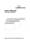
RDD100 Remote Digital
Display User Manual
RDD100 User Guide
Table of Contents
1
Introduction
1.1
1.2
2
Equipment Set Up
2.1
2.2
2.3
2.4
2.5
2.6
2.7
3
Operating Temp Range
Storage Temp Range
Relative Humidity
Dimensions
6.1
6.2
6.3
2
Voltage
Current
Power Connection
Operating Environment
5.1
5.2
5.3
6
Start Up Messages
Error Indications
3.2.1 Transducer Not Connected
3.2.2 Incorrect Baud Rate
3.2.3 Not Set Up To Continuously Transmit
3.2.4 Wrong Polarity Of DC Power
3.2.5 Transducer Disconnected While Transmitting
3.2.6 Over/Under-Ranged Transducer Indications
Power Requirements
4.1
4.2
4.3
5
Cables & Connections
Personal Computer Set Up
Set Transducer Baud Rate
Setting Transducer Display Units
“Continuous Transmit” Mode
Changes Stored In EEPROM
Verifying Stored Parameters
Operation
3.1
3.2
4
Product Overview
Transducer Description
Overall
Panel Cutout Dimensions
Depth Behind Panel
www.honeywell.com
RDD100 User Guide
1
INTRODUCTION
1.1
Product Overview
The Honeywell Remote Digital Display, RDD100, produces a digital display of measured pressures and is
designed for use with RS-232 versions of Honeywell HPA, HPB, PPT, PPTE, and PPTR pressure transducers.
The 6-digit display features 0.56 inch-tall LED characters that are readable in bright sunlight. The RDD100 is a
digital-input instrument, accepting a continuous stream of digital data transmitted in RS-232 format from the
transducer. The transducer may be installed at the source of the pressure being measured; a cable up to 50 feet
in length may separate the transducer from the RDD100. A wall-mounted AC-to-DC power supply, which powers
both the RDD100 and the transducer, is supplied with the display. Alternatively, a user may provide 12V ± 3V DC
from a system power supply.
The RDD100 has a 9-pin “D” connector mounted on the rear panel to connect to a personal computer. The
computer can perform data collection while the RDD100 is continuously displaying readings. The computer can
also be used to send commands to the transducer (two-way communications).
The RDD100 is housed in a compact enclosure, measuring approximately 3.8 x 2 x 4.4 inches, W x H x D. The
instrument may be used on a tabletop or can be easily installed in a panel using the supplied mounting hardware.
1.2
Pressure Transducer Description
The RDD100 receives pressure readings from an RS-232, Honeywell pressure transducer (HPA, HPB, PPT,
PPTE and PPTR). Accuracy of the displayed pressure reading is determined solely by the accuracy of the
transducer. Typical PPT accuracy, for example, is ±0.05% of full scale (FS). Digital output resolutions up to
0.0011% FS are possible but are dependent upon the pressure display units selected. Although many of the
support transducers also have a 0-5V analog output, only the digital output is used by the RDD100 as it provides
better resolution and accuracy. Any of 16 different pressure display units may be selected for use with the
RDD100. A list of available pressure units is shown in section 2.4 below. A more complete description of the
Honeywell transducers can be found in their respective user manuals. See http://www.pressuresensing.com.
2
EQUIPMENT SET UP
2.1
Cables & Connections
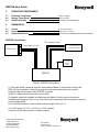
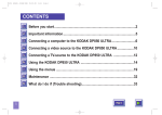
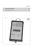
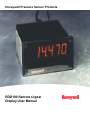
Figure 1 shows connections that must be made between the RDD100 and Honeywell RS-232 pressure
transducer. A six foot long cable for this connection is supplied with the RDD100. Figure 1 also shows
connections to the 12V DC input power. To obtain transducer pressure readings, only these two connections are
needed. Figure 1 also shows a connection to a personal computer. This connection may be used for data
logging or to communicate with the transducer in order to set up and change various parameters (display units,
integration time, idle count, etc). A six or ten foot long computer-to-RDD100 cable can be selected when the
RDD100 is ordered.
2.2
Personal Computer Set Up
The RS-232 transducer must be configured to send continuous readings to the RDD100 in order for pressure
readings to appear. The display will remain blank and the error LED will be lit continuously when the RDD100
fails to receive continuous input from a transducer.
Transducers ordered with the RDD100 will be configured at the factory to function properly with the RDD100. A
transducer that has not been configured for continuous readings can be configured for use with the RDD100 by
connecting it to the COMM port of a PC as shown in Figure 1. The HPA/B, PPT, PPTR/E Demo program or a
terminal emulator program such as HyperTerminal, may be used to send RS-232 formatted serial data to the
COMM port.
www.honeywell.com
3
RDD100 User Guide
The Demo program or PC terminal emulator port parameters should be set up as follows:
Baud Rate
Start Bits
Data Bits
Stop Bits
Parity
Local Echo
9600
1
8
1
None
On
Also, configure the program to attach a line feed to the carriage return. This completes the set up of the PC
terminal emulator.
Next, the transducer must be configured to match the above terminal emulator settings. (Settings listed above
are the factory default settings for the HPA, HPB, PPT, PPTE and PPTR, and are therefore likely to be correct.)
2.3
Set Transducer Baud Rate
When a Honeywell digital transducer, connected to a computer as described above, is first powered up a start-up
message will be sent from the transducer. If the transducer baud rate is not set at 9600, either no message or a
garbled message will be received. In this case, it will be necessary to try other baud rates until a match is found.
Possible baud rates for the HPA, HPB, PPT, PPTR and PPTE are: 1200, 2400, 4800, 9600, 14400, 19200, and
28800. Once a match is found, the transducer can be changed to a baud rate of 9600, which will allow it to
communicate with the RDD100 instrument.
The procedure for changing and then storing a new baud rate for the transducer is shown below. The commands
below all use a broadcast address (99) to allow them to operate correctly even if the transducer address has been
changed from the factory default setting, which is address 01.
With the PC and transducer operating at the baud rate found to return a non-garbled start-up message:
Type
Resp
Type
Resp
*99we<cr>
(Carriage Return)
*99WE
(Command Echo)
*99bp=n9600<cr>
*99BP=N9600 (Command Echo)
This will change the transducer to 9600 baud with no parity. Once this command is executed, the PC will again
lose communication with the transducer, since they will be on different baud rates. Do no power down the
transducer at this point since the change is only temporary. The PC terminal emulator can now be changed to
9600 baud and should be able to communicate with the transducer. This can be checked by typing *99p1<cr>
which should return a single pressure reading.
Continue as follows in order to store the new baud rate and parity into the transducer EEPROM:
Type
Resp
Type
Resp
*99we<cr>
*99WE
*99sp=all<cr>
*99SP=ALL
(Command Echo)
(Store Parameters Command)
(Command Echo)
After cycling power to the transducer it should now communicate with the PC, set at 9600 baud.
2.4
Setting Transducer Display Units:
Inquiry for the current display units
Type *99du<cr>
Resp ?01DU=PSI
(If transducer factory defaults have not been changed.)
Resp *99DU
(Command Echo)
To change the display units:
Type *99we<cr>
4
www.honeywell.com
RDD100 User Guide
Resp
Type
*99WE
(Command Echo)
*99du= {selection-see DU list below}
(A list of available pressure display units can also be found in the associated transducer User’s Manual.)
Resp
*99DU= {selected display units} (Command Echo)
Display Units List
Display Unit
PSI Multiplier
Units Description
ATM
BAR
CMWC
FTWC
INHG
INWC
KGCM
KPA
MBAR
MMHG
MPA
MWC
PSI
USER
LCOM
PFS
0.068046
0.068948
70.304
2.3065
2.0360
27.679
0.070307
6.8948
68.948
51.714
0.0068948
0.70304
1.0000
0.0010000-999.99
FS=60000
FS=100.000
ambient atmosphere at sea level
bar (105 newtons/meter2)
centimeters of water column (4ºC)
feet of water column (4ºC)
inches of mercury (0ºC)
inches of water column (4ºC)
2
kilograms/centimeters
kilopascal
millibar (1 hectopascal)
millimeters of mercury (0ºC) or torr
megapascal
meters of water column (4ºC)
pounds per square inch
user supplied
(1)
logic common value
percent of full scale in 0.001%
Increments
(1)
The LCOM display unit (logic common) automatically switches the digital pressure output to a scale, which has
60000 as the full scale output. The output will have a decimal point in the same position as it was in the original
psi scale. For example, when a 10 psia device is switched to DU=LCOM, the full scale digital pressure output will
be 60.000, instead of 10.000. Also, a 500 psi device will output full scale 600.00 instead of 500.00. PFS
generally provides the highest readout resolution available when using the RDD100 readout.
2.5
“Continuous Transmit” Mode
Type
Resp
Type
Resp
2.6
(Command Echo)
(Continuous Pressure Transmit Command)
(Command Echo)
Changes Stored In EEPROM
Type
Resp
Type
Resp
2.7
*99we<cr>
*99WE
*99mo=p2<cr>
*99MO=P2
*99we<cr>
*99WE
*99sp=all<cr>
*99SP=ALL
(Write Enable Command)
(Command Echo)
(Store Parameters Command)
(Command Echo)
Verifying Stored Parameters
After cycling power to the transducer the RDD100 should now display pressure readings in the selected display
units. If there is a need to interrogate the transducer to observe its set-up parameters, this can be done using the
following sequence:
Type
Resp
*99du<cr>
*99DU=INHG
(If transducer is set to read inches of mercury)
Although the Display Units example was used, this method of interrogation will work with any of the set up
parameters, listed above and in the associated User’s Manuals.
Note: Since pressure units are not a part of the RDD100 display, the user may want to attach a sticker or some other
indication of the pressure units either on or near the display window.
www.honeywell.com
5
RDD100 User Guide
3
OPERATION
3.1
Start Up Messages
When the RDD100 is powered up, it goes through a test of its display segments and its error LED. The error LED
is located beneath the least significant digit of the display. All segments should light for a brief period and then
the display transitions to “rdd100” followed by the message “rEAdY”.
If a transducer is properly set up and connected to the RDD100, pressure readings will appear on the display.
3.2
Error Indications
3.2.1 No Transducer Connected
If the RDD100 does not detect a transducer set to send continuous readings, the display will go through the
segments and LED check, display “rdd100”, display “rEAdY” and then go dark with the error LED illuminated.
3.2.2 Incorrect Baud Rate
If the RDD100 sees a transducer, set to the wrong baud rate, the display will go through the segments and LED
check, display “rdd100”, display “rEAdY” and hold with the “rEAdY” message.
3.2.3 Not Set Up To Continuously Transmit
If the RDD100 sees a transducer that has not been set up to continuously transmit, the display will go through the
segments and LED check, display “rdd100”, display “rEAdY” and hold with the “rEAdY” message.
3.2.4 Wrong Polarity Of DC Power
The RDD100 is equipped with the reverse polarity protection diodes at its power input. The instrument will
operate with either polarity.
3.2.5 Transducer Disconnected While Transmitting
If the transducer is disconnected while transmitting, the last reading received will remain on the display and the
error LED will light, indicating that no further updates are being made. Reestablishing connection to the
transducer will result in a continuation of reading updates and the error LED will turn off.
NOTE: the RDD100 may appear to be in this condition if the transducer has been programmed with a long
integration time or idle count yielding long durations between readings. It is recommended that the transducer be
programmed to provide 1 or more readings per second to prevent this possible confusion. (The typical factory
default reading rate is 5/second.)
3.2.6 Over/Under-Ranged Transducer Indications
In the event that a transducer, experiencing an applied pressure or temperature which is over or under the
specified range, is connected to the RDD100, the following will be indicated:
Sequence #1:
If a transducer that is in an over/under ranged condition is connected to the RDD100 and then the power is
applied to the RDD100, the result will be a start-up message that continuously displays “rEAdY”.
Sequence #2:
If the RDD100 is powered up and then an over/under ranged transducer is connected to the RDD100, the result
will be a blank display and the error LED will light.
Once the over/under range condition is removed, normal operation of the RDD100 will be restored.
4
POWER REQUIREMENTS
4.1
Voltage
4.2
Current
4.2.1 Operating
4.2.2 @ Start-Up
4.3
6
Power Connection
12 ± 3 VDC
….170 mA (Transducer and RDD100 together)
.350 mA
2.5 x 5.5 x 10 mm (I.D. x O.D. x length)
www.honeywell.com
RDD100 User Guide
5
OPERATING ENVIRONMENT
5.1
5.2
5.3
Operating Temp Range
Storage Temp Range
Relative Humidity
6
DIMENSIONS
6.1
6.2
6.3
Overall
Panel Cutout Dimensions
Depth Behind Panel
-20ºC to +60ºC
-25ºC to +85ºC
0% to 90%, non-condensing
3.8 in. W x 2.0in.H
3.58 in. W x 1.77in.H
….4.5 inches (not including connectors and cables)
RDD100 Connections
(2) 6
Personal Computer
S
e
C
r
O
i
M
a
l
(1)
ft. transducer cable
1/A
2/B
4/D
5/E
9-pin cable, 6 or 10 ft.
Honeywell RS-232
Pressure Transducer
Wallmounted
12V DC
supply
(3)
2 3 5
1 2 4 5
RDD100
Figure 1, RDD100 Connections
(1) This cable allows a personal computer, with suitable software, to communicate through the
RDD-100 to the transducer. Data can be logged and transducer parameters set/reviewed.
Length of cable can be chosen when RDD100 is ordered.
(At the PC, USB to RS-232 converters can be used.)
(2) Separate cables are available for transducers with Metal or Plastic electrical connectors.
Standard cable length is 6 feet (1.8 m). Connectors may be purchased from Honeywell to construct
custom-length cables.
Due to RS-232 limitations, recommended maximum length is 50 ft (15 m).
(3) 12 VDC plug is 2.5 x 5.5 x 10 mm (I.D. x O.D. x length)
Center pin may be either positive or negative polarity.
Honeywell International Inc.
12001 Highway 55
Plymouth, MN 55441
Tel: 800-323-8295
www.honeywell.com
www.honeywell.com
Form #900221
September 2005
©2005 Honeywell International Inc.
7