1
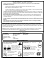
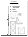
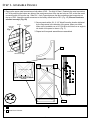
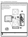
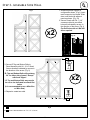
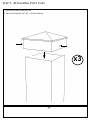
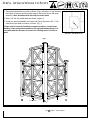
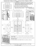
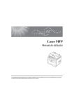
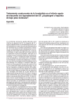
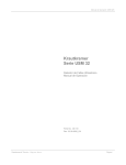
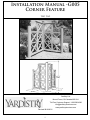
Installation Manual -G005
Corner Feature
YM11562
63 ½”
(1.61m)
(1m)
(1m)
(1.18m)
(1.18m)
Yardistry Ltd.
Mount Forest, ON Canada N0G 2L1
Toll Free Customer Support: 1.888.509.4382
[email protected]
Revised 08/24/2011
1
www.yardistrystructures.com
!Important Safety Notice!
•
Yardistry components are intended for privacy, decorative and ornamental use only. Product is NOT
INTENDED for the following:
- A safety barrier to prevent unsupervised access to pools, hot tubs, spas, or ponds.
- Safety railings for elevated platforms or decks.
- As load bearing support for a building, structure, heavy objects or swings. - Used in structures that trap
wind, rain or snow that would create extra load on the product.
•
Permanent structures may require a building permit. As the purchaser and or installer of this product you
are advised to consult local planning, zoning, and building inspection departments for guidance on applicable
building codes and or zoning requirements.
•
Wood is NOT flame retardant and will burn. Grills, fire pits and chimneys are a fire hazard if placed too
close to a Yardistry structure. Consult user’s manual of the grill, fire pit or chimney for safe distances from
combustible materials.
•
During installation, follow all safety warnings provided with your tools and use OHSA approved safety
glasses.
•
Some structures may require two or more people to install safely. Check for underground utilities
before digging or driving stakes into the ground!
General Information: Wood components are manufactured with Cedar (C. Lanceolata) which is protected with
factory applied water-based stain. Knots, small checks (cracks) and weathering are naturally occurring and do
not affect the strength of the product. Annual application of a water-based water repellent sealant or stain will help
reduce weathering and checks.
Keys to Assembly Success
Tools
Required
Warranty: Yardistry Limited products are backed by a 5 year limited lifetime warranty from the date of original
retail
purchase
and if installed as• Open
per manufacturer’s
installation
• Tape
Measure for manufacturing
• #1, defects
#2 & #3 Phillips
End Wrench
• 3/16”instructions.
Hex Key
• Carpenters Level
• Carpenters Square
• Claw Hammer
• Standard or Cordless Drill
• Tape Measure
or Robertson Bits
(7/16”, 1/2” & 9/16”)
Patents Pending
or Screwdriver
• Adjustable Wrench
• Ratchet with extension Tools Required
• 1/8” & 3/16” Drill Bits
(1/2” & 9/16” sockets)
• Pencil
• #2 Phillips or Robertson
Bits or Screwdriver
Part
Identification
Key
• Carpenters
Level
On each page, you will find the parts
andDrill Bit
• 1/8”
• Carpenters
Square
quantities
required
to complete the assembly
Pencil
step illustrated on that page. Here• is
a sample.
• Standard or Cordless
Drill
Symbols
• 8’ Step Ladder
• Safety Glasses
• Adult Helpers
• Safety Glasses
• Adult Helpers
2X A1 Post 2 x 4 x83”
• 8’ Step Ladder
Quantity
Key Number
Part Description, Part Size
Throughout these instructions symbols are provided
as To
important
reminders
for proper and safe assembly.
Keys
Assemble
Success
This identifies information that requires special
attention. Improper assembly could lead to an
unsafe or dangerous condition.
Use
Help
Measure
Distance
Use
Help
Check that set or assembly is properly level
before proceeding.
Pre-drill 1/8” & 3/16” Bit
Where this is shown, 2 or 3
people are required to safely
complete the step. To avoid
injury or damage to the
assembly make sure to get help!
Check that assembly is square
before tightening bolts.
Pre-drill a pilot hole
before fastening screw
or lag to prevent
splitting of wood.
Square
Assembly
Tighten
Bolts
This indicates time to tighten bolts, but
not too tight! Do not crush the wood.
This may create splinters and cause
structural damage.
Use a measuring tape to assure
proper location.
No
CAUTION – Protrusion Hazard
Use
Level
2
Yes
If Bolt protrudes
beyond T-Nut
Material List
R
Top and Bottom Rail -2x 3’ 3 1/2” (1m) and 2x 2’ 2 3/4” (67.9cm)
S4
S4
S4
S7
#8 x 2 1/4” Wood Screw
S5
S4
S7
S5
#10 x 1” Pan Head Screw
P
4x4 Posts - 1x 63” (1.60m) and 2x 49 1/4” (1.25m)
S7
S7
S6
S5
#8 x 1 1/2” Wood Screw
S6
S5
(3) Post Caps
S6
(12) Panel Clips
PA1 (2)Arch Topper
PX1
PX2 (4) Two High X Panel
3
(2) One High X Topper
Insert male into female. Slide down until flush with
required.
adjacent panel.
s. Step 1- Assemble Panels
Introduzca
el extremo macho
en el extremoexigée
hembra.pour votre projet.
res
et les panneaux
dans l'orientation
Deslícelo hacia abajo hasta que quede al ras del
1. Remove the upper metal connectors on both sides of PX2 - Two High X Panel. Reattach the metal connectors
panel
adyacente.
to PX2 by securing the bottom two holes of the metal connectors to the top two holes on PX2 so that the metal
stick out from the top. Slide PA1 – Arch Topper between the two protruding metal connectors on
Insérezconnectors
les pièces
de raccordement mâles dans les
the top of PX2. Attach the metal connectors to the factory drilled holes in PA1. (Fig. 1A) *Ensure Panels are
pièces de raccordement femelles. Faites glisser le
oriented correctly! (Fig. 1B)
panneau vers le bas jusqu'à ce qu'il soit au même
niveau que le panneau adjacent. 2. Secure panels with a S4 - 2 1/4” Wood Screw the location indicated
Groove
Thick Piece
of Wood
Skinny Piece
of Wood
Fig. F
by the large arrow in the direction of the arrow. When pre-drilled
holes are not available use a 1/8” Drill Bit to drill holes on an angle in
the inside of the panel as shown. (Fig. F)
3.Repeat until two panel assemblies are assembled.
Note orientation of keyhole.
d reattach using
n panel.
2 1/4” Screw
y vuelva
a
eros
*U
ac
de
inc
jue
po
de
*L
fo
p
2
Tenga en cuenta la orientación
del agujero
de la cerradura.
PA1
Notez l'orientation de l'encoche
en trou deserrure.
Drill Hole on an Angle
accordement et
n des deux trous
t Remove
été percés
à connectors from the outside of the
the male
panel assembly.
Sc
inc
2x
Pilot holes to the right
Quite los conectores masculinos del exterior de la
asamblea de panel.
short male
connector
conector
masculino
corto
x2
PX1
One Arch Topper
2x
PX2
Two High X Panel
conector
masculino
connecteur
mâle
Fig. 1B - Filler Strips
on Bottom
Enlever les connecteurs
mâles
de l'extérieur de
of Panel!
l'assemblée de panneau.
2x
male
connector
Fig. 1A
le connecteur
mâle court
Do not remove Small Connector
PX2
No retire los conectores
2x
4
S4
retirez
#8- 2 1/4” WoodNe
Screws
pas les petites pièces d
raccordement.
Step 2- Assemble Panels Continued
4. Remove the upper metal connectors on both sides of PX2 - Two High X Panel. Reattach the metal connectors
to PX2 by securing the bottom two holes of the metal connectors to the top two holes on PX2 so that the metal
connectors stick out from the top. Slide PX1 - One High X Topper between the two protruding metal connectors
on the top of PX2. Attach the metal connectors to the factory drilled holes in PA1. (Fig. 4A) *Ensure Panels
are oriented correcly! (Fig. 4B)
5. Secure panels with a S4 - 2 1/4” Wood
Screw the location indicated by the large
arrow in the direction of the arrow.
6.Repeat until two panel assemblies are
created.
Note orientation of keyhole.
and reattach using
on panel.
Tenga en cuenta la orientación
del agujero PX1
de la cerradura.
Notez l'orientation de l'encoche
en trou deserrure.
es y vuelva a
gujeros
e raccordement et
yen des deux trous
ont été percés à
Pilot holes to the right
Fig. 4B - Filler Strips on Bottom
of Panel!
Fig. 4A
Do not remove Small Connec
x2
2x
PA1
One High x Topper
2x
PX2
Two High X Panel
PX2
No retire los conectores
Ne retirez pas les petites pièce
raccordement.
2x
5
S4
#8- 2 1/4” Wood Screws
Step 3- Assemble Side Wall
1. Assemble panels together in
configuration shown. (Fig.1) Insert
male connector into female. Slide
down until flush with adjacent
panel as shown. (Fig. 1A)
Fig. 1
asic Guidelines
or Panel Assembly
Cut and attach
Top and Bottom
Toppers to Panels.
3
Pautas básicas para Instruc
Pautas
básicas
para Instructions de base
1 Assemble
pour l'
el
ensamblado
Instale los topes en los paneles. pour l'assemblage
Basic
Guidelines
2. Secure Panels with S4 - 2 1/4” de des
pa
el ensamblado
de
los los
paneles
for Panel Assembly
Corte
y
fije
rieles
superior
e
Assemblez les pièces supérieures des panneaux
Les assem
screws
provided in pre-drilled
et les panneaux.
los paneles
Shown here are configurations using Las ilustraciones muestran
configuraciones con topes. También pièces supé
a Topper. 2as
and 3 indicated
High Panels can
Les assemblages illustrés comportent desholes
by
arrows,
également
pueden
conectar
y 3 in
paneles couran
etsealtos
fixez
la 2main
also be connected Taillez
together as
à deux ou à
own here are configurations using Las ilustraciones muestran
a medida que se adquieran.
pièces
supérieures.
Il
est
possible
purchased.
the direction of the*Use
arrow.
(Fig.1)
configuraciones con topes. También
los tornillos de acero inoxidable (vendus sé
*Use 2 1/4" stainless steel screws
opper. 2 and 3 High Panels can
également d'assembler des panneaux Pre-Drill
de 2 1/4"
que
se incluyen
en el juego *Utilisez
One
sencillo
Une les
p
holes
with
aAncho
1/8th
drill
included in the Panel
Clip
set to Wide
se pueden conectar 2 y 3 paneles
2-1/4 po fou
de sujetadores de paneles para
o be connected together as
secure
and strengthen
theside.
assembly.
Assemble
Panels
side by
(Maximum
3 wide x 3 high) 20"
B.
à
deux
ou
à
trois
carreaux
de
hauteur
fixations
po
20"
bit as required. reforzar el ensamblado.
altos a medida que se adquieran.
de renforce
chased.
(vendus séparément).
Conecte los paneles lado a lado.
*Use
los
tornillos
de
acero
inoxidable
se 2 1/4" stainless steel screws
Assemble
Assemblez
à côte.Panels side by side.
2 les panneaux côte
de 2 1/4" que se incluyen en el juego *Utilisez les vis en acier inoxydable de
luded in the Panel Clip set to
Conecte
a lado.
Fig.
1Alos paneles
Instructions
de
base
Cut
and
attach
Toplado
and
Bottom
2-1/4
po
fournies
dans
le
nécessaire
de
Two
Wide
Ancho
doble
Deux p
Pautas
básicas
para
deConnectors
paneles
Remove Large
and para
reattach using top two
cure and strengthen the assembly. de sujetadores
Assemblez
les
panneaux
côte
à
côte.
l'assemblage
pour
factory drilled holes on panel.
fixations
pour
panneaux
afin
de
fixer
et
39½"
elreforzar
ensamblado
el ensamblado. de
sic Guidelines
Corte y fije los rieles superior e
Retire los conectores grandes y vuelva a instalarlos
de renforcer
l'assemblage.
des
panneaux
usando los dos agujeros pretaladrados del panel.
+
Panel Assembly
x2
=
3
los paneles
Retirez les grandes pièces de raccordement et fixez-les
Les assemblages illustrés comportent des
Taillez
fixezAncho
la main
muestran
Note
Tenga en cuenta Notez l'orientation
de nouveau au
moyen des deux trous
Threeet
Wide
triple courante
Trois pièc
wn here are configurationsAssemble
using Las ilustraciones
Panels
side
by
side.
orientation Il
la orientación
del de l'encoche en
pièces supérieures.
est possible
supérieurs du
panneau
qui ontTambién
été percés
trou de serrure.
of keyhole. agujero de la
configuraciones
con
topes.
pper. 2 and 3 High Panels can
59"
à l'usine.
cerradura.
One Wide
Ancho sencillo
Une piè
los paneles
a lado. également d'assembler des panneaux
se pueden
conectar 2lado
y 3 paneles
be connected together as Conecte
à
deux
ou
à
trois
carreaux
de
hauteur
20"
20"
altos a medida que se adquieran.
hased.
Assemblez
les panneaux côte à côte.
*Use los tornillos de acero inoxidable (vendus séparément).
2 1/4" stainless steel screws
Four Wide
Ancho cuádruple
Qu
Insert male into female. Slide down until flush with adjacent panel
de 2 1/4" que se incluyen en el juego *Utilisez les vis en acier inoxydable de
ded in the Panel Clip set to
78
2-1/4 po fournies dans le nécessaire de
macho en el
extremo hembra.
Deslícelo
ha
TwoIntroduzca
Wideel extremo
Ancho
doble
Deux
3. Connect
last pi
asse
abajo hasta que quede al ras del panel adyacente.
re and strengthen the assembly. de sujetadores de paneles para
fixations
pour
panneaux
afin
de
fixer
et
39½"
reforzar el ensamblado.
Insert male
into
Slide down
until
with
Insérez
les female.
pièces de raccordement
mâles
dansflush
les pièces
de renforcer l'assemblage.
adjacent
depanel.
raccordement femelles. Faites glisser le panneau
Fig. 2
vers le bas jusqu'à ce qu'il soit au même niveau que
Introduzca
el extremo
le panneau
adjacent. macho en el extremo hembra.
R Three
Deslícelo hacia abajo
hasta que
quede
al ras del
Wide
Ancho
triple
panel adyacente.
Do not remove Small Connectors.
Assemble Panels side by side.
Conecte los paneles lado a lado.
No retire los conectores Insérez les pièces de raccordement mâles dans les
pequeños.
pièces de raccordement femelles. Faites glisser le
Trois pièce
59"
panneau vers le bas jusqu'à ce qu'il soit au même
wood piece at bottomcôte
prevents à côte.
Assemblez
les Note
panneaux
3. Secure R-Top
and Bottom
Rails
collection
of water. to
pieza deWood
madera inferior
Panel Assembly with S4Note
- que
2 la1/4”
evita la acumulación de agua.
Screws locations indicated
by
arrows
Prenez note que la pièce en boisin
située au bas de chaque élément
deSlide
l'assemblage
empêche
Insert male
into female.
down
the direction
of the
arrow.
(Fig.
2)until flush with adjacent panel.
l'accumulation d'eau.
Ne retirez pas les petites pièces
niveau que le panneau adjacent.
de raccordement.
Four Wide
Introduzca
el extremo
el extremo hembra.
Deslícelo
hacia
3. Connect
last assembled
panels to make a fence section.
*R- Top and
Bottom
Railsmacho
willen
overhang
Secure with Screws*. Use factory drilled holes.
hasta
que quede
al ras del
panel adyacente.Asegure el ensamblado usando tornillos*. Use los agujeros pretaladrados.
1/4” on abajo
either
side
of panel.
*Except
Fixez l'assemblage au moyen de vis.* Servez-vous des trous prépercés à l'usine.
with Arch
sérez les pièces de raccordement
mâlesTopper!
dans les pièces
e raccordement
femelles.
Faites
glisser leRails
panneau
*R- Top
and
Bottom
may need to
ers le bas jusqu'à ce qu'il soit au même niveau que
be cut to size indicated in material list
panneau adjacent.
Ancho cuádruple
x2
Qua
78½
Los torn
y se incluyen
*Les vis sont celles de 2-1/4 po en acier inoxydable qui sont fournies dans le
Los rieles superior e
Top and Bottom Rail will
male
Fije el to
overhang 1/4"on either side. a cada lado.
connector
en los agujeros
preta
Attach Top with Screws*
Remove the male connectors from the outside of the
C. panel assembly.
Insert male into female.
Slide adown
until Box
flush with adjacent panel.
conector
un espa
through factory drilled holes. inferior, deje
(It is recommended
to use
Mitre
tornillos* y masculino
los borde
On Bottom, space Screws*
Quite los conectores masculinos del exterior de la
or el
Mitre
Saw)
Introduzca
extremo
macho en el extremo hembra.
Deslícelo
hacia
3. Connect
last assembled
panels to make a fence
section.
connecte
4"
from
edges
of
panels.
asamblea de panel.
mâle
abajo
hasta
que
quede
al
ras
del
panel
adyacente.
4. Repeat to create two walls.
Enlever les connecteurs mâles de l'extérieur de
panel_cap_labels_19x9.5.indd 7
below.
l'assemblée de panneau.
érez les pièces de raccordement mâles dans les pièces
accordement femelles. Faites glisser le panneau
s le bas jusqu'à ce qu'il soit au même niveau que
anneau adjacent.
2x
R
Top & Bottom Rail at 3’ 3 1/2” (1m)
2x
R
Top & Bottom Rail at 2’ 2 3/4” (67.9cm)
18x
S4
Top and R
Bottom Rail will
1/4" 1/4"on either side.
overhang
Attach Top with Screws*
through factory drilled holes.
On Bottom, space Screws*
1/4"edges of panels.
from
#8- 2 1/4” Wood 4"
Screws
short male
connector
conector
masculino
corto e in
superior
Los rieles
a cada lado. leFije
el top
connect
mâle
court
en los agujeros
pretala
inferior, deje un espac
tornillos* y los bordes d
Screws* are 2 1/4" stainless
steel included in Panel Clip set.
Los tornillos* son de acero inoxidable de 2 1/4"
y se incluyen en el juego de sujetadores de paneles.
}
*Les vis sont celles de 2-1/4 po en acier inoxydable qui sont fournies dans le nécessaire de fixations pour panneaux.
6
1/4"
4"
Step 4- Attach Panel Clips For Wings
1. On a flat surface place P- 4x4 Post on its side and position Panel Clips in
locations indicated in Figures 1 and 1A. Ensure Panel Clips are oriented
as shown in Diagrams!
Fig. 2
2. Panel Clips should be placed in the centre of the post or the leading edge
of the clip should be 1 3/8” or 3.49cm away from the side of the post as
shown in Fig. 2.
3. With Panel Clips in place, mark screw holes with a pencil and pre-drill
holes with a 1/8” drill bit. (Not provided)
4. Secure Panel Clips in locations indicated in figure 1 and 1A with S7- #8 x 1
1/2” wood screws.
1 3/8”
(3.5cm)
Pre-drill holes and secure with S7- #8 x
1 1/2” Wood Screws
5. Repeat for each post configuration.
Fig. 1A- Top View
C
Note: Post A has Panel
Clips on two sides!
A
B
Side View
Fig. 1
Front View
Fig. 1
A
B
C
(138.2cm)
(111.8cm)
(111.8cm)
38”
(96.5cm)
38”
(96.5cm)
(20.3cm)
(20.3cm)
2x
P
4x4 Post at 49 1/4” (1.25m)
12x - Panel Clips
1x
P
4x4 Post at 63” (1.60m)
24x S7 #8 x 1 1/2” Wood Screw
7
38”
(96.5cm)
(20.3cm)
Step 5- Attaching Post Caps
1. Place a Post Cap on each 4x4 Post
2. Secure Post Cap with 2 S7- #8- 1 1/2” Wood Screws
x3
3x Post Caps
6x 8
S7
#8- 1 1/2” Wood Screws
This identifies information that requires special
Check that set or assembly is properly level
before proceeding.
Step 6- A
ttach
to
attention. Wings
Improper assembly
couldPosts
lead to an
unsafe or dangerous condition.
Use
Use
Pre-drill 1/8” & 3/16” Bit
Where this is shown, 2 or 3
Help
Help
Pre-drill a pilot hole
1. Place panel assemblies on posts as shownpeople
(Fig.1)
a safely
2” gap between
areallowing
required to
before fastening screw
the step.rail
To avoid
the bottom of the post and the bottom edgecomplete
of the bottom
on the panel
or lag to prevent
injury
or
damage
to
the
assembly. Note: Assemble with the help of another adult!
splitting of wood.
assembly make sure to get help!
2. With a 1/8” drill bit, predrill holes as shown in figure 2.
Measure to Check
that and
assembly
is Clips
squarewith aSquare
3. Fasten the panel assembles
the post
Panel
S5- 1” Pan
Distance
Assembly
before
tightening
bolts.
Head Screw provided in location of circles. (Fig. 1)
This indicates time to tighten bolts, but
*Posts must be securely installed
to support structure. Consult local not too tight! Do not crush the wood.
Use a measuring tape to assure
building codes and ground conditions
for required footing design. It is This may create splinters and cause
proper location.
recommended the structure be secured to existing stone, concrete or structural damage.
deck.
Fig. 2. Predrill Holes and Fasten
No S5- 1” Pan Head Screw
with
If Bolt protrudes
beyond T-Nut
CAUTION – Protrusion Hazard
1
Once the assembly is tightened, watch forFig.
exposed
threads. If a thread protrudes from the T-Nut, remove
the bolt and add washers to eliminate this condition.
Extra washers have been provided for this purpose.
Use an extra
Flat Washer
Lag Screw
For bolts, tap T-Nut into hole with
hammer. Insert the hex bolt through
lock washer first then flat washer then
hole. Because the assemblies need to
be squared do not completely tighten
until instructed. Pay close attention to
diameter of the bolts. 5/16” is slightly
larger than 1/4”.
Before mounting
use factory drilled
guides to drill 1/8
Flat Washer
Bolt Assembly
Hex Bolt
Lock
Washer
Note: Wafer head bolts with blue lock
tight or a bolt with a Ny-Lok nut do
NOT require a lock washer.
Flat
Washer
T-Nut
(Hammer
Do not cr
6
12x
P
2” (5.1cm)
Ye
Lag Assembly
Proper Hardware Assembly
Lag screws require drilling pilot
holes to avoid splitting wood. Only
a flat washer is required. For ease of
installation liquid soap can be used
on all lag-type screws.
B
Tigh
Bo
A
2” (5.1cm)
4x4 Post
12x S5 #10 x 1” Pan Screws
9
C