1
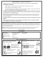
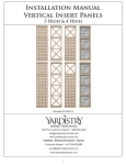
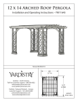
Installation Manual
Privacy Wall & Decorative
Panel Kit
Yardistry
Mount Forest, ON Canada N0G 2L1
Toll Free Customer Support: 1.888.509.4382
[email protected]
www.yardistrystructures.com
Revised 04/18/2012
1
!Important Safety Notice!
•
Yardistry components are intended for privacy, decorative and ornamental use only. Product is NOT
INTENDED for the following:
- A safety barrier to prevent unsupervised access to pools, hot tubs, spas, or ponds.
- Safety railings for elevated platforms or decks.
- As load bearing support for a building, structure, heavy objects or swings. - Used in structures that trap
wind, rain or snow that would create extra load on the product.
•
Permanent structures may require a building permit. As the purchaser and or installer of this product you
are advised to consult local planning, zoning, and building inspection departments for guidance on applicable
building codes and or zoning requirements.
•
Wood is NOT flame retardant and will burn. Grills, fire pits and chimneys are a fire hazard if placed too
close to a Yardistry structure. Consult user’s manual of the grill, fire pit or chimney for safe distances from
combustible materials.
•
During installation, follow all safety warnings provided with your tools and use OHSA approved safety
glasses.
•
Some structures may require two or more people to install safely. Check for underground utilities
before digging or driving stakes into the ground!
General Information: Wood components are manufactured with Cedar (C. Lanceolata) which is protected with
factory applied water-based stain. Knots, small checks (cracks) and weathering are naturally occurring and do
not affect the strength of the product. Annual application of a water-based water repellent sealant or stain will help
reduce weathering and checks.
Keys to Assembly Success
Tools
Required
Warranty: Yardistry products are backed by a 5 year limited lifetime warranty from the date of original retail
purchase
for manufacturing defects
if installed as per •manufacturer’s
• Tape Measure
• #1, #2 and
& #3 Phillips
Open End Wrench installation instructions.
• 3/16” Hex Key
• Carpenters Level
• Carpenters Square
• Claw Hammer
• Standard or Cordless Drill
• Tape Measure
or Robertson Bits
(7/16”, 1/2” & 9/16”)
Patents Pending
or Screwdriver
• Adjustable Wrench
• Ratchet with extension Tools Required
• 1/8” & 3/16” Drill Bits
(1/2” & 9/16” sockets)
• Pencil
• #2 Phillips or Robertson
Bits or Screwdriver
Part
Identification
Key
• Carpenters
Level
On each page, you will find the parts
andDrill Bit
• 1/8”
• Carpenters
Square
quantities
required
to complete the assembly
Pencil
step illustrated on that page. Here• is
a sample.
• Standard or Cordless
Drill
Symbols
• 8’ Step Ladder
• Safety Glasses
• Adult Helpers
• Safety Glasses
• Adult Helpers
2X A1 Post 2 x 4 x83”
• 8’ Step Ladder
Quantity
Key Number
Part Description, Part Size
Throughout these instructions symbols are provided
as To
important
reminders
for proper and safe assembly.
Keys
Assemble
Success
This identifies information that requires special
attention. Improper assembly could lead to an
unsafe or dangerous condition.
Use
Help
Measure
Distance
Use
Help
Check that set or assembly is properly level
before proceeding.
Pre-drill 1/8” & 3/16” Bit
Where this is shown, 2 or 3
people are required to safely
complete the step. To avoid
injury or damage to the
assembly make sure to get help!
Check that assembly is square
before tightening bolts.
Pre-drill a pilot hole
before fastening screw
or lag to prevent
splitting of wood.
Square
Assembly
Tighten
Bolts
This indicates time to tighten bolts, but
not too tight! Do not crush the wood.
This may create splinters and cause
structural damage.
Use a measuring tape to assure
proper location.
No
CAUTION – Protrusion Hazard
Use
Level
2
Yes
If Bolt protrudes
beyond T-Nut
12x12 Arched Roof Pergola - YM12505
12x12 Complete Pergola Room - YM11507
Fencing
3
Material List
R
(2) Top and Bottom Rail
P_1
Note: Wall assembly in this instruction
is shown as a 3 High Lattice Panel with
a 1 High X Topper. Depending on kit
purchased, images may not be accurate.
Please see front cover for what your
final set-up should look like. You may
also refer to page 3 for what assemblies
may look like inside the different units.
(4) One High X Topper or,
S4
(4) One High Lattice Topper or,
(4) One High Faux Glass Topper or,
(2) One High Arch Topper and (2) of the above
S4
P_3
S4
S7
#8 x 2 1/4” Wood Screw
S5
S4
S7
S5
#10 x 1” Pan Head Screw
S7
S7
S6
S5
#8 x 1 1/2” Wood Screw
S6
S5
(4) Three High Lattice Panel or,
(4) Three High X Panel
S6
(6) Panel Clips
Privacy & Decorative Panel Kits:
4 High Privacy Lattice / X Panel - YM11515
4 High Lattice with Faux Glass Panel - YM11517
4 High Privacy Lattice Panel - YM11540
4 High Decorative X Panel - YM11544
4 High Decorative X / Arch Panel - YM11548
4 High Privacy Lattice/ X / Arch Panel - YM11549
4
Step 1- Assemble Panels
1. Remove the upper metal connectors on both sides of P_3 - Three High_Panel. Reattach the metal connectors
to P_3 by securing the bottom two holes of the metal connectors to the top two holes on P_3 so that the metal
connectors stick out from the top. Slide P_1 – One High_Topper between the two protruding metal connectors
on the top of P_3. Attach the metal connectors to P_1. (Fig. 1A)
*Ensure Panels are oriented correctly! (Fig. 1B)
2. Secure panels with a S4 - 2 1/4” Wood
Screw the location indicated by the large
arrow in the direction of the arrow.
Note P_1
orientation of keyhole.
3.Repeat until four panel assemblies are
created.
d reattach using
n panel.
Tenga en cuenta la orientación
del agujero de la cerradura.
y vuelva a
eros
Notez l'orientation de l'encoche
en trou deserrure.
accordement et
n des deux trous
été percés à
Pilot holes to the right
Fig. 1B - Filler Strips on Bottom
of Panel!
x4
Fig. 1A
Do not remove Small Connector
P_3
No retire los conectores
Ne retirez pas les petites pièces d
raccordement.
4x
P_1
One High _Topper
4x
P_3
Three High _ Panel
4x
5
S4
#8- 2 1/4” Wood Screws
Step 2- Assemble Wall
Fig. 1
1. Assemble panels together in
configuration shown. (Fig.1) Insert
male connector into female. Slide
down until flush with
adjacent
Pautas
básicas para Instruc
Instructionspanel
de base
Cut
and
pour l'T
el ensamblado
de attach
Basic
Guidelines
as shown. (Fig.
1A)
des pa
3
Pautas básicas para
for Panel Assembly los paneles
l'assemblage
pour
assem
el ensamblado de
Las ilustraciones
muestran y fije Les
here are configurations
using
Corte
los
r
2. SShown
ecure
Panels
with
S4
2
1/4”
pièces
supé
des
panneaux
configuraciones
con
topes.
También
a Topper. 2 and 3 High Panels can
los paneles
également
conectar 2 y 3 paneles
also be connected
together as
screws
provided
inse pueden
pre-drilled
1 Assemble Toppers to Panels.
Instale los topes en los paneles.
Basic Guidelines
for Panel Assembly
Assemblez les pièces supérieures
et les panneaux.
à deux ou à
Les assemblages illustrés
comportent des altos a medidaTaillez
que se adquieran.
purchased.
et fixez
(vendus sél
*Use
los arrows,
tornillos de acero inoxidable
as indicated
by
in
*Use 2possible
1/4" stainless
steel screws
pièces supérieures. Ilholes
est
*Utilisez les
de
2
1/4"
que
se
incluyen
en
el
juego
included in the Panel Clip set to
2-1/4 po fou
de arrow.
sujetadores de One
paneles para
the
direction
of
the
(Fig.1)
également d'assembler
des
panneaux
Wide
Anch
secure
and
strengthen
the
assembly.
3 wide x 3 high)
B. Assemble Panels side by side. (Maximum
fixations
po
reforzar el ensamblado.
de renforce
à deux ou à troisConecte
carreaux
de
hauteur
20"
los paneles lado a lado.
(vendus séparément).
Assemble
Assemblez
à côte.Panels side by side.
2 les panneaux côte
*Utilisez les vis en acier inoxydable de Conecte
Fig. 1Alos paneles lado a lado.
à côte.Anc
2-1/4 po fournies dans le nécessaire deAssemblez les panneaux
Two côte
Wide
fixations pour panneaux afin de fixer et
Instructions
de base
Cut and attach3T
de renforcer l'assemblage.
Shown here are configurations using Las ilustraciones muestran
configuraciones con topes. También
a Topper. 2 and 3 High Panels can
se pueden conectar 2 y 3 paneles
also be connected together as
altos a medida que se adquieran.
purchased.
*Use los tornillos de acero inoxidable
*Use 2 1/4" stainless steel screws
de 2and1/4"
que se incluyen en el juego
included in the Panel Clip set
to Large Connectors
Remove
reattach using top two
factory drilled holes onde
panel.
sujetadores
de paneles para
secure and strengthen theRetire
assembly.
los conectores grandes y vuelva a instalarlos
reforzar
el del
ensamblado.
usando los dos agujeros
pretaladrados
panel.
+
=
Pautas básicas para
pour l'assemblage
Note
Tenga en cuenta Notez l'orientation
el ensamblado de
Basic Guidelines
orientation la orientación del de l'encoche en
des
panneaux
trou de serrure.
of keyhole. agujero
de la
losPanels
paneles
Assemble
side by side.
for Panel Assembly
cerradura.
2
Retirez les grandes pièces de raccordement et fixez-les
de nouveau au moyen des deux trous
supérieurs du panneau qui ont été percés
à l'usine.
3
Corte y fije los r
Three Wide
Anc
Les assemblages illustrés comportent des
Taillez et fixez l
ilustraciones
Conecte
los
panelesmuestran
lado a lado. pièces supérieures. Il est possible
Shown here are configurations
using Las
configuraciones
con
topes.
También
a Topper. 2 and 3 High Panels can
également d'assembler des panneaux
One Wide
Anch
Assemblez
les panneaux
côte à côte.
se pueden
conectar 2 y 3 paneles
Insert male into female. Slide down until flush with adjacent panel
also be connected together as
à
deux
ou
à
trois
carreaux
de
hauteur
20"
Four
Wide
Anc
altos a medida que se adquieran.
Introduzca el extremo macho en el extremo hembra.
Deslícelo
ha
3. Connect
last asse
purchased.
(vendus
séparément).
abajo hasta que quede al ras del panel adyacente.
*Use los tornillos de acero inoxidable
*Use 2 1/4" stainless steel screws
en acier
inoxydable
de
male
into
Slide down
until
with
Insérez
les female.
pièces de raccordement
mâles
dansflush
les pièces
de 2 1/4" que se incluyen en el juego *Utilisez les vis Insert
included in the Panel Clip set to
adjacent
panel.
de
raccordement
femelles.
Faites glisser le panneau
2-1/4
po
fournies
dans
le
nécessaire
de
Two Wide
Anc
vers le bas jusqu'à ce qu'il soit au même niveau que
secure and strengthen the assembly. de sujetadores de paneles para
Introduzca
el extremo
pour panneaux
afin
de
fixermacho
et en el extremo hembra.
ez l'orientation
le panneau
adjacent.
Fig.fixations
2
3
reforzar el ensamblado.
Deslícelo hacia abajo hasta que quede al ras del
encoche en
R
panel adyacente.
denotrenforcer
l'assemblage.
Do
remove Small Connectors.
3.
S
ecure
R-Top
and
de serrure.
No retire los conectores Insérez les pièces de raccordement mâles dans les
Bottom Rails to Panel
pequeños.
pièces de raccordement femelles. Faites glisser le
Three Wide
Assemble
Panels
side
by
side.
panneau vers le bas jusqu'à ce qu'il soit au même
Ne retirez pas les petites pièces
Note wood piece at bottom prevents
Assembly with S4 - 2 1/4”
niveau que le panneau adjacent.
de raccordement.
collection of water.
losinferior
paneles lado a lado.
Wood Screws locations NoteConecte
que la pieza de madera
evita la acumulación de agua.
indicated by arrows in Prenez
Assemblez
les panneaux côte à côte.
note que la pièce en bois
située au bas de chaque élément
the direction of the arrow.
de l'assemblage empêche
Four Wide
l'accumulation d'eau.
Insert
male into female. Slide down until flush with adjacent panel.
(Fig. 2)
2
Anc
Anc
Secure with Screws*. Use factory drilled holes.
Introduzca el extremo machoAsegure
en elel extremo
hembra.
Deslícelo
hacia
3. Connect
last assembled
panels to make a fence section.
Los torn
ensamblado usando tornillos*. Use los agujeros pretaladrados.
y se incluyen
abajo
hasta
que
quede
al
ras
del
panel
adyacente.
Fixez
l'assemblage
au
moyen
de
vis.*
Servez-vous
des
trous
prépercés
à
l'usine.
ez l'orientation**R- Top and Bottom
*Les vis sont celles de 2-1/4 po en acier inoxydable qui sont fournies dans le
encoche enRails Insérez
will overhang
les pièces de 1/4”
raccordement mâles dans les pièces
de serrure.
on either
side of femelles.
panel. Faites glisser le panneau
de raccordement
*Exceptvers
with
Arch
le bas
jusqu'àTopper!
ce qu'il soit au même niveau que
Top and Bottom Railmale
will
le panneau adjacent.
connector
overhang 1/4"on either
side.
*R- Top and Bottom Rails
the male connectors from the outside of the
C. Remove
Attach Top with Screws*
conector
panel assembly.
may
need
to
be
cut
to
all Connectors.
through factory drilledmasculino
holes.
Quite los conectores masculinos del exterior de la
6’ 6 1/2” (2m)
On
Bottom,
space
Screws*
connecte
asamblea
de
panel.
tores
mâle
Insert male into female. Slide down until flush with adjacent panel.
4" from edges of panels.
Enlever les connecteurs mâles de l'extérieur de
panel_cap_labels_19x9.5.indd 7
l'assemblée de panneau.
Introduzca el extremo macho en el extremo hembra.
Deslícelo
hacia
3. Connect
last assembled
panels to make a fence section.
(It is recommended toabajo hasta que quede al ras del panel adyacente.
petites pièces
use a Mitre Box or Mitre
Insérez les pièces de raccordement mâles dans les pièces
Saw)
de raccordement femelles. Faites glisser le panneau
vers le bas jusqu'à ce qu'il soit au même niveau que
le panneau adjacent.
all Connectors.
2x
R
Top & Bottom Rail - 78 1/2”
24x
tores
1x R Top & Bottom Rail - 78 1/2”
y drilled holes.
1x R Top & Bottom Rail - 53 1/2” (135.8 CM)
pretaladrados.
petites pièces
***Use If you have purchased YM11549 or YM11548,
ercés à l'usine.
S4
#8- 2 1/4” Wood Screws
Screws* are 2 1/4" stainless
steel included in Panel Clip set.
short male
connector
conector
masculino
corto
le connect
1/4"
mâle court
Top and R
Bottom Rail will
overhang 1/4"on either side.
Attach Top with Screws*
1/4" factory drilled holes.
through
On Bottom, space Screws*
4" from edges of panels.
Los tornillos* son de acero inoxidable de 2 1/4"
y se incluyen en el juego de sujetadores de paneles.
to accommodate the arch topper.
*Les vis sont celles de 2-1/4 po en acier inoxydable qui sont fournies dans le nécessaire de fixations pour panneaux.
6
1/4"
Step 3- Installing Panel Clips
ni spilC lenaP noitisop dna edis sti no tsoP 4x4 -P ecalp 1.
ecOn
afruas flat
tafl surface
a nO .1 place P- 4x4 Post on its side and positio
in Figures 1 and 1A. Ensure Panel Cl
detneiro era spilC lenaP erusnE .A1 dna 1 serugiF ni detalocations
cidni snoitindicated
acol
!smargaiDas
nishown
nwohsin
saDiagrams!
1. Postition Panel Clips in locations indicated in Figures 1 and 1A. Orient Panel Clips according to whether
Clips
de visible
gnidael eor
ht rnot.
o tsop(i.e
ehtfacing
fo ertnecinside
eht ni dor
ecafacing
lp eb dlu2.
ohPanel
s outside.)
spilC
lenashould
P .2 be placed in the centre of the post or t
you want them toegbe
the
sa tsop eht fo edis eht morf yawa mc5.3 ro ”8/3 1 eb dluof
ohthe
s piclip
lc ehshould
t fo be 1 3/8” or 3.5cm away from the side o
shown
Fig.
2. should be 1 3/8” or 3.5cm
.giF nof
i in
nwthe
ohsclip
2. Panel Clips should be placed in the centre of the post or the leading.2edge
n
i
s
p
i
l
C
l
e
n
a
P
n
o
i
t
i
s
o
p
d
n
a
e
d
i
s
s
t
i
n
o
t
s
o
P
4
x
4
P
e
c
a
l
p
e
c
a
f
r
u
s
t
a
fl
a
n
O
.1
away from the sideniofspllthe
as
shown inedsFig.
2.
Panel
iirlC
d-elepost
rn
padPnan
aclpalnpi 3.
sp
ilC
aflP ahtnClips
iW
oliictinseopp adnhatiw
iselsothi nwoetrscosPkr4axm
4 ,-ePce
e
cWith
a
frule
sn
ta
O ..3
1 in place, mark screw holes with a pencil
dnei tsnpeiliCroleenraaPsn
poiliC
rudsisnsEti.n
Ao1 tdsnoaP 14xs4er-uPgieFca
nlipde
e1.
nfloaitsurface
ancOol.1 place P- 4x4 Post on its side and positio
tisloepnadP
naee
ctaacfOn
ridunsiatsaflat
1/8”
vo
p stoeN
ib nlliirdde”t8a/holes
anihstwith
inwosite
h drill bit. (Not provided)
deplace,
tneiro era spilscrew
C lenaP erusnwith
E .)Ad1eddin
ar1
ru( g.tiF
c1indholes
aalco
rgeataiD
solal a 1/8”
3. With Panel Clips din
pre-drill
bit.1(Not
provided)
etneiro ermark
a spilC lenaPholes
erusnE .A1adnpencil
a 1 serand
ug!is
Fm
na
id
cilocations
dni insw
nooih
twith
asindicated
co
in drill
Figures
and 1A.
Ensure Panel C
!oslmnai rsgpai4.
iDSecure
wo
aClips
Panel
1 x 8# -7S htiw A1 dna 1 erugfi ni detacidni snoita!cs
C
lenininanw
P
rhs
uscsesaS
.4 in locations indicated in figure 1 and 1
margailD
n
oeh
as
inPDiagrams!
egin
delocations
gnidael ehtindicated
ro tsop ehtinfofigure
ertnec 1ehand
t ni d1A
ecawith
lp eb S7dluoh#8
s sshown
pil1C 1/2”
lena
.2
4. Secure Panel Clips
screws.
rscssx
”screws.
2a/P
1wood
egde gnidael eht ro tsop eht fo ertnec eht ni decalp eb d.sluwoeh1/2”
pdwood
io
lCow
len
.2
hh
t tforoed
/3e1bedbludo2.
lh
usoPanel
hsspiplC
ilcClips
o.2
egdesa
gntsidoapee
le
tsisopehethm
t foorfeyrtanw
eca emhct5n.i3dreoc”a8lp
leenhat Pfshould
be placed in the centre of the post or
sa tsop eht fo edis eht morf yawa mc5.3 ro ”8/3 1 eb d1..lu
o.h
siFapnflat
ilicnew
hot hfos place P- 4x4 Post on its side and positio
On
surface
2
g
sa tsop eht fo edis eht morf yawa mc5.3 ro ”8/3 1 eb dluoof
hsthe
pilcclip
ehtshould
fo
be 1 3/8” or 3.5cm away from the side o
.2 .giF ni nwindicated
ohs
in Figures 1 and 1A. Ensure Panel Cl
.s2plocations
gCiFlennianP
wthe
oFig.
sfollowing
in
2.
llird-erp dna licnep a hwtiewiVspeolToh wercs krNote:
am ,ecIfalyou
p ni purchased
i.lshown
h
thiW
.3
Top View
as
shown
in
Diagrams!
llird-erp dna licnep a htiw selohdweedrivco
s krunits:
aomN,(e.ctiYM11549
alp ni s8p/i1lCor
nYM11548.
P htioW
aleleh
iaw
h.3.3 You
llird-erp dna licnep a htiw seloh)w
ercs krp
ratm
,ecablpllnirids”p
ntaPanel
P shetilW
3.ilC
With
Clips
in place, mark screw holes with a pencil
)dedivorp MUST
toN( .tib llird 2.
”8the
/Panel
1 atop
htiClips
w
seloshould
h 65” to
bebit.
placed
the centre of the post or t
clips
at
tooNit(ac.toiblmount
hatP
iwwith
ecloaeh
holes
drill
(Notin
provided)
1 x 8# -7S htiw A1 dna 1 erugfi ni d)edteadciivdonripsn
nlliirsdp”i8lC/1of
lean
esru
S1/8”
.4 be
the
clip
should
1
3/8”
or
3.5cm
away from the side o
accomadate
the
arches.
1 x 8# -7S htiw A1 dna 1 erugfi ni detacidni snoitacol ni spiw
lCelrecnsadPooew
ruc
.4
”e2eS/S
12.
1 x 8# -7S htiw A1 dna 1 erugfi ni detacidni snoitacol ni sp.islC
eSecure
naP ein
ru
cFig.
.4
4.lshown
Panel
Clips in locations indicated in figure 1 and 1
.swercs doow ”2/1
1 3/8”
.swer1/2”
cs dowood
ow ”2screws.
/1
3. With Panel Clips in place, mark screw holes with a pencil
(3.5cm)
Top View
holes with a 1/8” drill bit. (Not provided)
weiV poT
Pre-drill holes and secure withweS7iV p#8
oT x
4. Secure Panel Clips in locations indicatedTop
in figure
View 1 and 1
1 1/2” Wood ScrewsweiV poT
1/2” wood screws.
1. On a flat surface place P- 4x4 Post on its side and positio
locations indicated in Figures 1 and 1A. Ensure Panel Cl
Top View
as shown in Diagrams!
Fig. 1A
D
Fig. 1
D
D
D
C
B
C
C
C
B
B
B
weiV tnorF
A
A
B
A
A
A
B
2. Panel Clips should be placed in the centre of the post or t
of the clip should be 1 3/8” or 3.5cm away from the side
o
Front
shown in Fig. 2.
A
3. With Panel Clips in place, mark screw holes with a pencil
holes with a 1/8” drill bit. (Not provided)
75”
A
weiV tnorF
weiV tnorF
weiV)tm
nocr9F.241(
75”
B
(190.5cm) in figure 1 and 1
4. Secure Panel Clips in locations indicated
1/2” wood screws.
(190.5cm)
56 1/4”
”4/1 65
)mc6.101(
Top View
40”
”04
(142.9cm
Fron
(101.6cm)
Front
40”
)mc9.241( ”4/1 65
”4/1 65
)mc9.241( ”4/1 65
)mc3.52(
)mc6.101( ”04
)mc6.101(
)mc6.101( ””0044
40”
(101.6cm))mc9.241(
10”
(25.3cm)
A
B
P
4x4 Post
(142.9cm
(25.3cm)
40” (101.6cm)
56 1/4” (142.9cm
)mc3.52(
)mc3.52(
)mc3.52(
10”
(25.3cm)
Note: these clip heights are designed for a 4” ground
clearance. For ground clearance less than 4” subtract equal
number from clip heights for appropriate measurement.
12x
56 1/4”
(101.6cm)
6x - Panel Clips
12x S7 #8 x 1 1/2” Wood Screw
7
40”
(101.6cm)
(25.3cm)
Front
(25.3cm)
56 1/4”
40”
(142.9cm
(101.6cm)
Step 4- Installing Wall Into
Flat Roof Pergola
1. With the help of an adult, place the Wall on Panel Clips as shown (Fig.1)
allowing a 4” gap between the bottom of the post and the bottom edge of
the bottom rail on the panel assembly.
2. With a 1/8” drill bit, predrill holes as shown in figure 2.
3. Fasten the Wall to the post and Panel Clips with a S5- 1” Pan Head Screw
provided in location of arrows. (Fig. 1)
Fig. 2. Predrill Holes and Fasten
with S5- 1” Pan Head Screw
Fig. 1
(10.2cm)
12x
P
4x4 Post
6x S5
8
#10 x 1” Pan Screws
Step 4- Installing Wall Into
Arched pergola
1. With the help of an adult, place the Wall on Panel Clips as shown (Fig.1)
allowing a 1” gap between the bottom of the post and the bottom edge of
the bottom rail on the panel assembly.
2. With a 1/8” drill bit, predrill holes as shown in figure 2.
3. Fasten the Wall to the post and Panel Clips with a S5- 1” Pan Head Screw
provided in location of arrows. (Fig. 1)
Fig. 2. Predrill Holes and Fasten
with S5- 1” Pan Head Screw
Fig. 1
1” (2.55 cm)
12x
P
4x4 Post
6x S5
9
#10 x 1” Pan Screws
Step 4- Installing Wall Into Fence
1. With the help of an adult, place the Wall on Panel Clips as shown (Fig.1)
allowing a 4” gap between the bottom of the post and the bottom edge of
the bottom rail on the panel assembly.
2. With a 1/8” drill bit, predrill holes as shown in figure 2.
3. Fasten the Wall to the post and Panel Clips with a S5- 1” Pan Head Screw
provided in location of arrows. (Fig. 1)
Fig. 2. Predrill Holes and Fasten
with S5- 1” Pan Head Screw
Fig. 1
4” (10.2cm)
12x
P
4x4 Post
6x S5
10
#10 x 1” Pan Screws