1
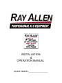
Gen2 INSTALLATION & OPERATION MANUAL System Serial No.___________________ Table of Contents 1 ) System Features...........................................................................................4 1.1 ) Heat Alert................................................................................................................... 4 1.2 ) Deployment................................................................................................................ 5 2 ) System Components....................................................................................6 2.1 ) Heads Up Display.......................................................................................................6 2.2 ) Control POD............................................................................................................... 7 2.3 ) Remote / Pager.......................................................................................................... 8 3) 4) 5) 6) Starting the System......................................................................................9 System Menu................................................................................................9 System Message Descriptions...................................................................12 Product Care and Service...........................................................................13 6.1 ) Heads Up Display.....................................................................................................13 6.2 ) Remote / Pager........................................................................................................ 13 7 ) Troubleshooting..........................................................................................14 8 ) Installation...................................................................................................15 8.1 ) Read This First!........................................................................................................15 8.2 ) Before installation.....................................................................................................15 8.3 ) Installation Kit Parts List...........................................................................................16 8.4 ) Charge the Remote/Pager........................................................................................18 8.5 ) Placement of the Control POD.................................................................................18 8.6 ) Electrical Specifications............................................................................................19 8.7 ) Wire Harness Details................................................................................................19 8.8 ) Window Lowering Feature Installation......................................................................22 8.9 ) Door Unlatch Solenoid Installation............................................................................23 8.10 ) Door Unlock Feature Connection...........................................................................24 8.11 ) Stainless Steel Gas Push Rod Installation..............................................................25 8.12 ) Park / Neutral Safety Connection...........................................................................26 8.13 ) Antenna Attachment...............................................................................................26 8.14 ) Temperature Sensor Placement.............................................................................27 8.15 ) Lights and Horn Connection...................................................................................27 8.16 ) MD10 F Ray Allen Fan Connection (Optional)........................................................27 8.17 ) Placement of Heads Up Display (HUD)..................................................................28 8.18 ) Completing the Installation.....................................................................................29 8.19 ) Testing the HEAT ALERT™ System......................................................................30 8.20 ) Testing the Tactical K9 Deployment System™.......................................................31 8.21 ) Confirming Normal Operation.................................................................................32 9 ) Warranty.....................................................................................................33 10 ) Disclaimer.................................................................................................34 F3-G2 System Manual - Rev 1 Page 2 of 34 Drawing Index Drawing 2.1.1: HUD Front..........................................................................................6 Drawing 2.1.2: HUD Display......................................................................................6 Drawing 2.2.1: Control POD Top...............................................................................7 Drawing 2.3.1: Remote/Pager Front..........................................................................8 Drawing 2.3.2: Remote/Pager Back..........................................................................8 Drawing 2.3.3: Remote/Pager Display.......................................................................8 Drawing 4.1: System Menu Diagram.......................................................................10 Drawing 4.2: System Menu Diagram - Advanced Settings.....................................11 Drawing 8.7.1: Connector Numbering.....................................................................20 Drawing 8.7.2: Typical Installation...........................................................................21 Drawing 8.8.1: Typical Window System Interface...................................................22 Drawing 8.9.1: Example Solenoid Placement.........................................................23 Drawing 8.10.1: Typical Lock System Interface......................................................24 Drawing 8.10.2: Dual Switch Configuration.............................................................24 Drawing 8.11.1: Suggested Push Rod.....................................................................25 Drawing 8.11.2: Push Rod Mounting Considerations..............................................25 Drawing 8.13.1: NMO Mount Modification...............................................................26 Drawing 8.17.1: Example HUD Mounting Locations...............................................28 Drawing 8.21.1: Functional HUD Display................................................................32 Drawing 8.21.2: Functional Remote / Pager Display...............................................32 Table Index Table 2.2.1: On-Board Fuse Values..........................................................................7 Table 5.1: Heat Alert Messages..............................................................................12 Table 5.2: Remote / Pager Message.......................................................................12 Table 8.3.1: Parts List..............................................................................................17 Table 8.6.1: Electrical Specifications.......................................................................19 Table 8.7.1: System Power Wire Harness...............................................................19 Table 8.7.2: Vehicle Interface Wire Harness...........................................................20 F3-G2 System Manual - Rev 1 Page 3 of 34 1 ) System Features 1.1 ) Heat Alert The heat alert system monitors temperature, vehicle power, and motion inside the kennel (optional) to determine if the K9 is in danger of overheating. Alert Delay: The alert delay postpones the heat alert function after system start-up or an alert reset. The duration of the delay is adjustable in the Heat Alert menu. Voltage Monitor: The voltage that is fed to the system is monitored for low voltage conditions. If the voltage drops below a specific level, a Vehicle Power Alert will be triggered. AUX Input: The system is equipped with an auxiliary input. triggered when this input is activated. An Aux Input Alert is AUX Output: The auxiliary output can be connected some other alarm device such as a strobe, siren, GSM dialer, etc. When an alert is triggered, this output will become active. The type of active signal can be programmed to fit the application. AUX Power: The auxiliary power output can supply vehicle power to a peripheral device. This output is only active when the F-Series system is powered on. Temp Sensors: The system utilizes two digital temperature sensors for high accuracy as well as decreased false alarms. Both the of temp sensors must be at or over the Alert Temp set in the Heat Alert menu to trigger an alert. Window Drop: The windows that are selected in the Heat Alert menu will roll down one at a time when a heat alert is triggered. The menu option can be set to roll down just the left, just the right, or both windows. Fan Control: The optional fan is controlled both manually and automatically. The manual fan control is through the right button of the HUD and can be set to three different speeds or turned off. When a heat alert is triggered and after the selected windows have rolled down, the system will automatically turn the fan on at full speed to aid in cooling down the kennel. Motion Sensor: The motion sensor is an optional feature that will detect motion inside the kennel for a specified amount of time after the system has been turned off. For example, if the Heat Alert system is powered down, but the K9 is accidentally left in the vehicle, the system will detect the motion of the K9 and enter an alert state. There are multiple adjustments that can be made to the timing of this feature. First, the Detect Delay is the number of minutes after the system is turned off before the system begins watching for motion. Next, the Detect Duration is the number of minutes the system watches for motion. Finally, the Alert Delay is the number of minutes the system will wait after motion has been detected before the actual alert is triggered. F3-G2 System Manual - Rev 1 Page 4 of 34 1.2 ) Deployment When the Deploy-K9 button is pressed on the Remote/Pager, a command is sent to the POD to unlock and then unlatch the deployment door so that the gas pushrod can push the door open. Park / Neutral Safety Input: When a deployment command is received by the POD, it check this input prior to activating the unlock and unlatch outputs. The purpose is to prevent the door from opening while the vehicle is in gear. Optionally, this input can be connected to the GPS Speed Monitor which will disable the deployment system when the vehicle is traveling over a specific speed. When the deployment system is disabled because of this input, the display will show a small “D” with and circle and slash over it. Otherwise, it will display a bold “D”. Unlock Output: This feature unlocks the deployment door prior to unlatching it. Unlatch Output: After unlocking the door, the system activates a solenoid inside the deployment door that is mechanically connected to the latch mechanism causing the latch to disengage. Window Drop: The left, right, or both windows can be set to drop immediately after a deployment. This feature, if used, is typically enabled on the deployment door in order to deter a second suspect from holding the deployment door closed. If used, there should not be a window guard installed on the deployment door. F3-G2 System Manual - Rev 1 Page 5 of 34 2 ) System Components 2.1 ) Heads Up Display The Heads Up Display (HUD) is the primary user interface used to monitor realtime temperature measurements and system status, manually control the kennel's fan (if installed), and adjust system settings. When an alert condition exists, the HUD will display the alert message and can be used to reset the alert. The HUD is equipped with a back-light for the display. It is controlled by the left button and can be set to one of three brightness levels or turned off. When the system is powered up, the back-light will return to the brightness level it was set at when it was last turned off. LCD Display Multifunction Buttons Remote/Pager Charging Port POD Interface Jack Drawing 2.1.1: HUD Front Temperature Trend Arrows Sensor Temperatures Deployment System Status Heat Alert System Status Back-light Level Fan Speed Button Label (Back-light) Button Label (Fan) Button Label (Press – Menus / Hold - Power) Drawing 2.1.2: HUD Display F3-G2 System Manual - Rev 1 Page 6 of 34 2.2 ) Control POD The Control POD is the main power switching and logic control device. The system settings are saved in non-volatile memory on the POD. This means that even if power is disconnected from the system, the settings are saved and don't need to be reset. Antenna Jack Temperature Sensor Plugs Power Plug Motion Detector Plug Vehicle Interface Plug HUD Interface Jack On-Board Fuses Drawing 2.2.1: Control POD Top Reference Function Value (A) F1 Fan 15A F2 Window - Left 20A F3 Horn 20A F4 Aux 20A F5 Lights 20A F6 Unlock 15A F7 Window - Right 20A Table 2.2.1: On-Board Fuse Values F3-G2 System Manual - Rev 1 Page 7 of 34 2.3 ) Remote / Pager The Remote/Pager (RP) is the portable interface to the system. It displays almost exactly the same information as the HUD. The RP will notify of an alert condition by vibrating and beeping (unless muted in which case it will only vibrate) and can be used to reset the alert. After approximately one minute of no buttons being pressed, the display will turn off to conserve battery power, but the RP will continue to receive updates. The RP is equipped with a back-light for the display which can be turned on by pressing the right button. The RP is powered by a lithium-polymer rechargeable battery. It can be recharged using either the included 120V wall charger or the included charging pigtail which allows the RP to be recharged from the HUD. It could take more than an hour to fully recharge the battery but can be left on the charger indefinitely without causing damage. This type of battery also does not have a “memory” effect and so there is no need to fully discharge the battery before recharging. Note: The Remote / Pager holster is constructed of a special polymer that can be cut to accommodate larger fingers to access the DEPLOY K-9 Button through the holster. LCD Display Deployment Button Multifunction Buttons Drawing 2.3.1: Remote/Pager Front Temperature Trend Arrows Signal Strength Deployment System Status Drawing 2.3.2: Remote/Pager Back Sensor Temperatures Battery Level Heat Alert System Status Button Label (Mute) Button Label (Press – Back-light / Hold - Power) Drawing 2.3.3: Remote/Pager Display F3-G2 System Manual - Rev 1 Page 8 of 34 3 ) Starting the System To power-up the system, hold down the center button located on the Heads Up Display (HUD). Release the button when the LCD changes. The system will perform a quick diagnostic. The display will show two independent temperature readings, and system status indicators. Along the bottom are controls for the backlight, fan (left and right button respectively), and menu access / power button. Note: Your system is powered by direct connection to the vehicle battery and will remain on and functioning even when the vehicle is turned off. Therefore when your vehicle is not in service and/or you no longer require this system to function, you must manually turn the system OFF (press and hold the center button of the HUD). 4 ) System Menu Access the particular system you wish to program by first pressing the center button on the HUD once. This brings you to the first level of your Setup menu. To access the feature sub-menus, select the desired feature with the left and right buttons and then press the center button to enter that sub-menu. To change a feature option, select the desired option with the left and right buttons and then press the center button to edit that option. The left and right buttons can then be used to change the option value. Once the option has been set to the desired value, pressing the center button will allow another option to be selected for editing. Holding the center button will exit out of the current sub-menu or menu. F3-G2 System Manual - Rev 1 Page 9 of 34 Drawing 4.1: System Menu Diagram F3-G2 System Manual - Rev 1 Page 10 of 34 OFF/ON OFF/LEFT/RIGHT/BOTH Window Drop: Sets which window(s) will drop immediately after a deployment is triggered. Deployment: This will enable or disable the deployment system. DEPLOYMENT: WINDOW DROP: DEPLOYMENT Alarm Mode: Sets which audible/visual alarms should be activated when the alarm delay has expired after an alert is triggered. Window Drop: Sets which window(s) will drop when a heat, vehicle power, auxilliary, or motion alert is triggered. Alert Delay: Sets the initial delay after system startup or a reset alert before heat alert system is active. Alert Temp: Sets the temperature that both temperature sensors must reach to trigger a heat alert. Temp Units: Sets temperature measurement units to fahrenheit or celcius. Heat Alert: Enables or disables heat alert system. Vehicle power alert and motion alert (if installed) are also affected by this setting. HEAT ALERT HEAT ALERT: OFF/ON TEMP UNITS: F/C ALERT TEMP: 70F – 99F (85) ALERT DELAY: 0m – 10m (2) WINDOW DROP: OFF/LEFT/RIGHT/BOTH ALARM MODE: OFF/LIGHTS/HORN/BOTH DEPLOYMENT HEAT ALERT MOTION TIMERS ADVANCED SETUP 1m – 10m (5) 5/10/15/20/25/30/CONT 1m – 3m (2) Alert Delay: Sets the number of minutes between motion being detected and an alert being triggered. Detect Duration: Sets the number of minutes the system will watch for motion. Detect Delay: Sets the number of minutes the system will wait before watching for motion. DETECT DELAY: DETECT DUR: ALERT DELAY: MOTION TIMERS Drawing 4.2: System Menu Diagram - Advanced Settings F3-G2 System Manual - Rev 1 Page 11 of 34 OFF/SNGL/PLS/CONT 1s – 20s (1) Aux Time: If AuxMode is set to a single pulse, this sets the duration of the pulse. If Aux Mode is set to continuous pulsing, this sets the duration of each pulse (and duration of each break between pulses) or half the period. If Aux Mode is set to continuous output, this setting has no effect. Aux Mode: Sets the type of auxiliary output when an alert is triggered (either none, a single pulse, continuous pulsing until the alert reset, or a continuous high output until the alert is reset). AUX MODE: AUX TIME: ADV - AUX OUTPUT 0s – 99s (30) 1s – 15s (5) 0.1s – 2s (0.5) Lock Time: Sets the number of seconds the unlock output will activate when unlocking the door for deployment. Window Time: Sets the number of seconds the window outputs will activate when dropping windows. Alarm Delay: Sets the number of seconds after an alert is triggered before the audible/visible alarm is activated. ALARM DELAY: WINDOW TIME: LOCK TIME: ADV – OUTPUT TIMING AUX OUTPUT OUTPUT TIMING RF PARAMS RESET ALL ADVANCED 11 – 25 (14) RF Channel: Sets the radio frequency channel to be used for wireless communications with the Remote/Pager. RF CHANNEL: ADV – RF PARAMS 5 ) System Message Descriptions Displayed Message Event Description Remote/Pager Behavior HIGH TEMP ALERT! The in-vehicle temperature Continuous, alternating is at or above the Alert vibrator and beeper (No Temp at both sensors. beeper if ‘MUTE’ is enabled). VEHICLE POWER ALERT! The vehicle battery voltage Continuous, alternating has dropped below vibrator and beeper (No approximately 8 volts. beeper if ‘MUTE’ is enabled). MOTION ALERT! The motion detector Continuous, alternating (optional) has detected vibrator and beeper (No motion inside the vehicle beeper if ‘MUTE’ is enabled). while the system is powered down AUX INPUT ALERT! The auxiliary input received a pulse. has Continuous, alternating vibrator and beeper (No beeper if ‘MUTE’ is enabled). Table 5.1: Heat Alert Messages Displayed Message LOW BATTERY NO SIGNAL XX:XX Event Description Remote/Pager Behavior The Remote/Pager battery Periodic vibration and beep needs to be recharged to (No beeper if ‘MUTE’ is ensure continued operation. enabled) The Remote/Pager has not received a signal from the POD for the time specified (approximate) Vibration and beep after 2 minutes and every 10 minutes after signal is lost (No beeper if ‘MUTE’ is enabled) Table 5.2: Remote / Pager Message F3-G2 System Manual - Rev 1 Page 12 of 34 6 ) Product Care and Service Your system has been designed to give years of trouble free use. Great effort was given to the selection of the highest quality components and fixtures. Following are tips and suggestions that will help keep your system fully functional. 6.1 ) Heads Up Display The Heads Up Display (HUD) can be cleaned with a soft, damp cloth. Do not use abrasive cleansers as they can damage the LCD panel and the housing. Your HUD requires no additional user maintenance. 6.2 ) Remote / Pager Your Remote/Pager (RP) is designed to be carried on a law enforcement duty belt. Included with your system is a custom belt holster that is engineered to offer durability, ease of use, and comfort when carrying the RP. Your RP can be cleaned with a soft, damp cloth. Do not use abrasive cleaners as they can damage the LCD panel and the case. Do not submerge the RP in water. However, if the RP does become immersed in water, turn it off immediately. Allow the RP to completely dry before attempting to charge or turn it on again. F3-G2 System Manual - Rev 1 Page 13 of 34 7 ) Troubleshooting • • • • The Remote/Pager is frozen and won't turn ON/OFF. ◦ The RP can be reset by momentarily holding down both of the front buttons at the same time. The range of the Remote/Pager is not very good. ◦ The wireless connection between the RP and the POD can be changed to a different channel if there are issues with interference. The channel can be changed on the POD by accessing the appropriate menu through the HUD. To change the channel on the RP, hold down the left, front button while the RP is powered down. Skip through the first screen which is used to set the serial number of the POD that the RP is to connect to. The next screen allows you to change the channel number. The system turns off when the RP is plugged into the HUD charging cord. ◦ When the RP battery is very low, sometimes the initial power demand causes the system to shut down. The system can be powered back up immediately and system operation should continue normally. The Remote/Pager does not connect. ◦ There is probably a difference of serial number or RF channel between the remote and the main system. Follow these steps to make sure that these two parameters match. ▪ Make note of the system serial number displayed on the HUD when it is turned on. It will be labeled “POD SN”. ▪ Make note of the RF channel located in SETUP → ADVANCED → RF PARAMS. ▪ With the RP turned off, press and hold the MUTE button until it powers up. The RP will then allow you to adjust the serial number one digit at a time. ▪ Adjust each digit to match the serial number displayed by the HUD pressing NEXT to advance to the next digit. After all four digits are set, press NEXT again. ▪ Adjust the RF channel to the same value as in the RF PARAMS menu and press DONE. The RP will power down. It can now be turned on normally and should connect quickly to the system. F3-G2 System Manual - Rev 1 Page 14 of 34 8 ) Installation 8.1 ) Read This First! Installation of this system should be carried out by qualified persons familiar with the general installation of law enforcement electronics commonly installed in police service vehicles. It is recommended that the installer(s) have updated wiring diagrams and schematics of the specific vehicle in which the system will be installed or have access to wiring information through a local dealership or other source. If you are replacing an existing deployment and/or heat alert system, remove all previous wiring before beginning installation. Our System requires that wiring connections be made as described in this manual - do not connect this to any other system’s pre-existing wires. Any deviation from these instructions that causes damage to any part of the system will void the warranty. 8.2 ) Before installation 1. Confirm all parts and components are included and accounted for by doing a complete inventory of the package contents. 2. Read this manual to familiarize yourself with the system’s unique requirements for installation. 3. Observe all safety practices. It is the installer’s responsibility to determine, implement, and observe those safety practices. Please note: This system is designed to be directly hardwired to the vehicle’s 12-volt battery. Do not connect the system to the vehicle battery until all connections have been completed and verified as being correct. Do not connect this product to any device intended to detect vehicle battery drain. Doing so may “power down” this product and/or render it ineffective for its intended use. We recommend that you meet with the intended user to discuss preferences and installation requirements specific to the system’s application and user comfort. F3-G2 System Manual - Rev 1 Page 15 of 34 8.3 ) Installation Kit Parts List Part Description Kit Qty Reorder PN Antenna 1 F97 10ft Antenna Cable 1 F77 Heads-Up Display (HUD) 1 F74 HUD Articulating Mount 1 w/Hardware Pack (4 screws/nuts) F95 Remote/Pager Unit 1 F71 Remote/Pager Holster 2 F91 120V Remote Charger 1 F99 In-Vehicle Remote Charging Pigtail 1 F98 F3-G2 System Manual - Rev 1 Page 16 of 34 Part Description Kit Qty Reorder PN System Control POD 1 F73 Stainless Steel Gas Push Rod 1 F87 Stainless Steel Push Rod Brackets w/ Hardware 2 F86 (2) 40 lb. 12-Volt Solenoid 1 F88 Control POD/HUD Communications 15ft Cable (Grey) F94 1 Temperature Sensor w/ 2 15ft cable (Grey w/Black Tip) F85 (2) Electrical Hardware Pack 1 None POD & HUD Attachment Hardware Pack (8 self-tapping screws) 1 None System Power Wire Harness (15ft) 1 F81 Vehicle Interface Wire Harness (15ft) 1 Table 8.3.1: Parts List F3-G2 System Manual - Rev 1 Page 17 of 34 8.4 ) Charge the Remote/Pager After unpacking the System we recommend that you immediately charge the Remote/Pager. To do this: 1. 2. 3. 4. Locate the Remote/Pager and charger. Plug the charger into a 120v 60hz receptacle (standard wall plug). Plug the charger into the charging port on the side of the Remote/Pager. The message CHARGING BATTERY will appear on the LCD screen of the Remote/Pager. Note: If the Remote/Pager battery is completely dead it may take a few minutes before the charging sequence begins. Note: We have provided you with a long-life Remote/Pager battery. Depending on temperature, it can take over an hour to fully charge this device. For your convenience, the Remote/Pager is protected by over-charge circuitry therefore it can remain on the charger indefinitely without fear of battery damage. 8.5 ) Placement of the Control POD Before starting your installation, consider the most appropriate placement of the system’s Control POD in the interior of the vehicle (the POD design requires that it be located inside of the passenger compartment). Be certain that: 1. Both wire harnesses can easily reach the Control POD as well as their intended point of connection to the vehicle components. 2. The antenna connector can be mounted to the roof of the vehicle and still make connection to the Control POD. 3. The Control POD/HUD Communications Cable can be routed from the HeadsUp Display to the Control POD. 4. The Control POD can be securely attached anywhere in the interior of the vehicle (it does NOT need to be grounded). Use the self-tapping screws included to secure the POD to the front panel of your K-9 insert or attach using 2-sided tape, Velcro® or any other attachment method you choose. All wire harnesses are provided with fifteen (15) feet of wire. communications cable and antenna cable are ten (10) feet long. The POD/HUD Note: Take care to route all wires away from excessive heat sources and points of possible abrasion. F3-G2 System Manual - Rev 1 Page 18 of 34 8.6 ) Electrical Specifications Input Voltage Supply Current (powered down) Supply Current (powered up) Remote / Pager Battery Life* Remote / Pager RF Frequency 6V – 16V 50mA – 60mA 100mA - 200mA 80h – 100h 2.4GHz Table 8.6.1: Electrical Specifications * This rating assumes that remote is idling with good, consistent connection with POD. Control POD/HUD Communications Cable • A four conductor, unshielded twisted pair CAT3 cable terminated on both ends with an RJ9 crimp plug Antenna • Roof mounted, external • Omnidirectional • Part 15 compliant reverse polarity SMA connector • 10 feet of cable • NMO high frequency connector 8.7 ) Wire Harness Details Pin # Wire Color Signal Name Signal Description 1 Red System Power Input Connect directly to positive battery terminal through included 40A fuse. 2 Orange Door Unlatch Solenoid Output Connect to white solenoid wire through included 35A fuse. 3 Blue Fan Output Connect to black fan wire to blow into cage. (This output provides ground for the fan. Do NOT short to positive battery voltage.) Do NOT connect to more than one fan. 4 Green System Power Ground Connect directly to negative battery terminal. Table 8.7.1: System Power Wire Harness F3-G2 System Manual - Rev 1 Page 19 of 34 Pin # Wire Color Signal Name Signal Description 1 Purple Left Window Output Connect to window motor wire that goes from 0 to 12 volts when window is rolled down. 2 Green / Black Park / Neutral Safety Input Connect to any vehicle signal wire that is switched to ground when vehicle is in park or neutral or connect to white wire of optional Ray Allen GPS speed sensor. 3 N/A No Connection N/A 4 Yellow Horn Output Connect to vehicle's horn or other auditory alarm device. 5 Grey Aux Output Multifunction auxiliary output. 6 Brown (or Orange) Door Unlock Output Connect to door lock actuator wire that goes from 0 to 12 volts when door is unlocked. 7 Blue Right Window Output Connect to window motor wire that goes from 0 to 12 volts when window is rolled down. 8 Purple / Black Left Window PassThrough Connect to window switch wire that goes from 0 to 12 volts when window is rolled down. 9 Grey / Black Aux Input Connect to any peripheral device that sends a 12 volt pulse when alert is desired. 10 Red / Black Aux Power Connect to any peripheral device that needs to be powered when system is turned on. 11 N/A No Connection N/A 12 White Lights Output Connect to vehicle's parking lights or any other visual alarm device. 13 Brown / Black (or Orange / Black) Door Unlock PassThrough Connect to lock switch wire that goes from 0 to 12 volts when door is unlocked. 14 Blue / Black Right Window PassThrough Connect to window switch wire that goes from 0 to 12 volts when window is rolled down. Table 8.7.2: Vehicle Interface Wire Harness 14 13 12 11 10 7 6 5 4 3 9 2 8 1 Drawing 8.7.1: Connector Numbering Diagram (viewed from wire side) F3-G2 System Manual - Rev 1 Page 20 of 34 Drawing 8.7.2: Typical Installation F3-G2 System Manual - Rev 1 Page 21 of 34 Heads-up display Motion detector optional Temp sensor 1 Temp sensor 2 Remote / Pager Bi-directional wireless link Splitter Antenna Up Down (RD) Up Down (BL) (BK) optional Up Down Fan Door lock switch Lock Unlock (BR/BK) (BR) Door lock motor Lock Unlock Parking lights (WH) (YL) (RD/BK) AND/OR (GY) (GR/BK) (GY/BK) Vehicle P/N switch OR GPS speed sensor optional Left window switch Up Down POS (PU/BK) Vehicle battery (PU) Left window motor Right window motor (BL) (BL) (OR) (GR) (BL/BK) Right window switch POD 4 3 2 1 (WH) 1 8 2 9 3 10 4 11 5 12 6 13 7 14 35A fuse Door unlatch solenoid (BK) NEG 40A fuse F3 System Typical Installation Horn GSM Antenna optional CO Detector optional Smoke Detector optional 8.8 ) Window Lowering Feature Installation The vehicle interface wiring harness included with this system has 2 wires designated for this feature for each rear side window. These wires should be routed from the ‘B’ pillar through the conduit into each door. Make the connection inside each door. To determine the wire in the door to splice into, activate the window switch and, using a volt-meter, determine which of the two wires connecting the control switch to the window motor changes from 0 to 12 volts during the lowering of the window (“down wire”). Cut this wire and connect the window output wire (identified from the vehicle interface harness table) to the motor side of this wire. Connect the window pass-through wire to the switch side of this wire. Butt-splices are included for these connections. Ensure these wires are connected correctly as switching them will cause a dead short that could cause damage to the system. The window activation duration should be adjusted through the Advanced Menu to a setting that is just long enough the drop each window completely. See the System Menu Diagram in the User's Manual for more information on adjusting this setting. blue / black or purple / black blue or purple Down wire Window switch Window motor Up wire Drawing 8.8.1: Typical Window System Interface F3-G2 System Manual - Rev 1 Page 22 of 34 8.9 ) Door Unlatch Solenoid Installation Note: The door unlatch solenoid comes with a large push button switch. Do not use this switch in this installation. Included is a heavy duty door unlatch solenoid that will give years of trouble free use. Follow the manufacturer’s recommendations for installation. The solenoid comes with an in-line 35A fuse assembly which must be installed between the short orange wire stub on the System Power Connector and the included 15 foot orange deployment wire. Be sure to align the solenoid so that the pull of the piston is in a straight line with the motion of the door unlatch mechanism. Also, be sure to avoid any part of the window track or the linkage used in raising and lowering the window. Drawing 8.9.1: Example Solenoid Placement Note: Cable needs to be adjusted so that door latch is fully actuated before piston bottoms out. Note: Be certain to properly ground the solenoid. The door may not be a good ground. Consider routing a separate wire from the solenoid ground wire and attaching it directly to the vehicle chassis or body. Note: The above mounting location is only a suggestion for placement on a newer-model Crown Vic. We do recommend that on a Dodge Magnum or a Charger you locate the solenoid directly above the mid-door bracket and the window motor on a horizontal straight line with the door lock. The Ray Allen Cruise Eze™ door panels allow enough room for the installation of this solenoid in that location. F3-G2 System Manual - Rev 1 Page 23 of 34 8.10 ) Door Unlock Feature Connection The wiring harness included with this system has two wires designated for this feature. These wires should be routed from the ‘B’ pillar through the conduit to the same door to which the door unlatch solenoid is installed. To determine the wire in the door used to activate this feature, locate the stock unlock motor located in the door and trace the wires to an accessible point within the door. Activate the door unlock feature with the vehicle controls and, using a volt-meter, determine the wire that changes from 0 to 12 volts during unlocking. Cut this wire and connect the system's door unlock output wire to the motor side of this wire. Connect the door unlock pass-through wire to the other side of this wire. Butt-splices are included for these connections. The unlock activation duration can be adjusted to either lengthen the output if the vehicle has a slower unlock cycle or shorten the output to minimize deployment time. See the System Menu Diagram in the User's Manual for more information on adjusting this setting. brown / black Unlock wire brown Lock switch Lock motor Lock wire Drawing 8.10.1: Typical Lock System Interface Some vehicle models employ a dual switch configuration which switches power to one side of the lock and switches ground to the other. To interface with this configuration, connect the system's unlock output wire to the stock unlock wire and to one side of the coil of a standard automotive relay. Connect the common terminal (30) to the stock lock wire and the normally open terminal (87) and the second side of the coil to ground. The system's unlock pass-through wire is not used. 87a 87 30 brown 85 86 Unlock wire Lock switch Lock motor Lock wire Drawing 8.10.2: Dual Switch Configuration F3-G2 System Manual - Rev 1 Page 24 of 34 8.11 ) Stainless Steel Gas Push Rod Installation The stainless steel gas push rod should be mounted to the same door to which the door unlatch solenoid is installed. Included is a variety of stainless steel hardware to mount the push rod. Be sure the push rod is mounted so it can push the door as far open as possible but also allow the door to be closed completely. We recommend that the push rod be installed on a very slight downward angle (from cylinder to rod) so that proper lubrication of the pressure seal can take place. Note: Locate the push rod so that it is not in a dangerous position for the K9’s entrance and exit of the vehicle. Body of piston must not make contact with anything when fully extended. Drawing 8.11.1: Suggested Push Rod Mounting Location less mor force, e dis tanc e Kennel insert Veh icle d oor (ope ne d) Vehicle door (closed) Door must be able to close completely before piston bottoms out. mor less e force dist , anc e Drawing 8.11.2: Push Rod Mounting Considerations F3-G2 System Manual - Rev 1 Page 25 of 34 8.12 ) Park / Neutral Safety Connection Note: If you are installing this unit into a 2003 or newer Tahoe or Yukon, please see separate instructions with the wire included with your System and disregard the first paragraph below. To properly activate this feature, the system looks for an open circuit to disable the Tactical K9 Deployment System™. Under the dash or somewhere else within the vehicle, locate the wire that reads 0 – 55Ω (OHMS) when the vehicle is in Park or Neutral and 315 Ω (OHMS) or higher (or a completely open circuit) when in gear. This signal can typically be found coming from the transmission's Park/Neutral switch. Carefully splice the green w/black stripe system wire into this circuit. You can bypass this feature by attaching this wire to a ground. This will allow the Tactical K9 Deployment System™ to operate at ALL TIMES – whether the vehicle is in gear or not. Some handlers request Park / Neutral Safety to be disabled so that option is available to you. Optional: The Park / Neutral Safety input wire can also be connected to the optional Ray Allen GPS Speed Monitor. See the GPS module installation instructions for further details. 8.13 ) Antenna Attachment The provided antenna cable assembly is 10 feet in length. The cable should be run from the POD to a 3/4” hole drilled through the roof of the vehicle. The antenna connector is a modified NMO style terminal. The center contact and plastic washer must be removed in order to attach the antenna. Drawing 8.13.1: NMO Mount Modification F3-G2 System Manual - Rev 1 Page 26 of 34 8.14 ) Temperature Sensor Placement You have been provided with two (2) Temperature Sensors which are specifically designed to work with this system. Each Sensor has fifteen (15) feet of cable. These Sensors are plugged into the system Control POD (the two plugs next to the antenna port – opposite side of the wiring harnesses). Care should be taken before deciding where their final mounting point should be. We have provided hook and loop fasteners (Velcro®) to secure these Sensors. Place the cable under the Velcro® so that the black Temperature Sensor is completely exposed. Consider: • Neither Sensor should be mounted in a position that is subject to direct sunlight nor in close proximity to air conditioning vents or the roof of the vehicle -- Doing so will give incorrect readings of the “true” temperature inside the vehicle. • Cables should be routed to avoid points of possible abrasion. • Be certain the K9 cannot get to the sensors. They are not chew proof. 8.15 ) Lights and Horn Connection Under the dashboard, at the fuse panel or under the hood of the vehicle, locate the wires used for these features. Activate the lights and the horn from inside of the vehicle. Using a volt-meter, determine the wire that changes from 0 to 12 volts when these features are activated. Carefully splice into this circuit. On certain vehicles it may be necessary to splice into the wiring circuit beyond relays and fuse boxes. 8.16 ) MD10 F Ray Allen Fan Connection (Optional) The Ray Allen MD10 F Fan is designed to bolt directly to either side of the front panel on the Ray Allen Cruise Eze™. Hardware for this installation is included with the Fan. When attaching the Fan to the front panel of your Cruise Eze™, we suggest you insert the bolts and washers from inside of the cage and place the nut on the Fan side. You do not want the nut on the inside of the cage as it has a higher profile than the bolt head and this may injure the dog. Also included is the wiring to connect directly to the system’s Control POD. To complete this connection, attach the fan output wire from the POD to the black wire on the fan (buttsplices are included for this connection). Connect the blue wire from the fan to a positive battery voltage. The POD is designed to control only one fan. Therefore, do not connect the POD's fan wire to multiple fans. Test this connection when testing the complete system. This fan is designed to blow “in” to the Cruise Eze™ unit. If for some reason you wish this fan to blow in the opposite direction, simply reverse these wire connections. F3-G2 System Manual - Rev 1 Page 27 of 34 8.17 ) Placement of Heads Up Display (HUD) The HUD is the system's user interface used for information read-outs and feature programming therefore easy access to the HUD visually and physically is vital. We have included an articulating mount that can be used for this purpose. This mount easily attaches to the HUD using the self-tapping screws included in your hardware pack. Once the location has been determined (we recommend the intended user be involved in this decision) the base of the mount can be permanently attached to the vehicle utilizing the two-sided tape already on the base. This tape is extremely adhesive so you will only get one shot at this. If you wish to mount the HUD directly to the dashboard as shown below (photo on the right), either attach the HUD using the self-tapping screws or attach with Velcro® or two-sided tape. Note: Take care to route the communication cable away from excessive heat sources or points of possible abrasion. On top of the dashboard On the facing of the dash Drawing 8.17.1: Example HUD Mounting Locations F3-G2 System Manual - Rev 1 Page 28 of 34 8.18 ) Completing the Installation Verify the following before proceeding: • All connections except the four-conductor, black system power connector are securely attached to the Control POD. • The other end of the gray data cable is connected to the HUD. • All wire splices and butt connectors are secure and that there is no chance of a short circuit. Once all of the above is completed, connect the System’s Power and Ground cables to the vehicle battery’s positive and negative terminals and plug the fourconductor, black system power connector into the POD. Power up the system by pressing and holding down the center button on the front of the HUD. When the display appears, release the button. The HUD will run a self diagnostic routine. Upon completion of this routine proceed to the following steps. F3-G2 System Manual - Rev 1 Page 29 of 34 8.19 ) Testing the HEAT ALERT™ System For this test it is important that all vehicle windows are closed. Start the vehicle and power up the HUD and the Remote/Pager. Be sure that the fan is off through the HUD. In the SETUP Menu, select HEAT ALERT, then set the system values as follows (refer to the Users Manual if necessary): HEAT ALERT TEMP MODE ALERT TEMP ALERT DELAY WINDOW DROP ALARM MODE “ON” “F” “70” “01” “BOTH” “BOTH” Exit the SETUP Menu. On the HUD display, insure that the H on the LCD is now bold without a circle w/line over it (if it is not bold, wait one minute for the “alert delay” to time-out). If necessary, turn on the vehicle heater and adjust to high to raise the interior temperature of the vehicle. When the interior of the vehicle reaches 70F and BOTH sensors indicate 70F or above. Heat Alert Test Sequence: 1. The HUD and the Remote/Pager will display HIGH TEMP ALERT. 2. The windows that have been wired into the system will lower. 3. After the windows have lowered, the system will turn on the fan at full speed (if the optional fan is installed). Approximately 30 seconds after a HEAT ALERT™ has activated and not been reset, the vehicle’s horn (if integrated) will sound and the lights (if integrated) will flash. If both the horn and lights are connected and selected in the ALERT MODES menu, they will alternate. The HEAT ALERT™ can be reset by pressing the RESET button once on the Remote/Pager or the HUD. The fan will continue to run at high speed and the windows will remain down but the heat alert will delay for one (1) minute (the amount of time set as the ALERT DELAY). Note: When this test is completed successfully, we suggest that you reset the ALERT TEMP to 85F. F3-G2 System Manual - Rev 1 Page 30 of 34 8.20 ) Testing the Tactical K9 Deployment System™ In the SETUP Menu select the DEPLOYMENT option, then set the system values as follows (refer to the Users Manual if necessary): DEPLOYMENT WINDOW DROP “ON” “BOTH” Exit the SETUP Menu. On the HUD display, insure that the D on the LCD is now bold without a circle w/line over it. Leave the door open but force the door latch shut with a screwdriver or similar instrument. Press the Deploy K-9 button located on the back of the Remote/Pager. Deployment Test Sequence: 1. The Remote/Pager will beep twice and vibrate once to acknowledge the deployment request. 2. The vehicle horn (if integrated) will beep signifying that the deployment request has been accepted. 3. The door will unlock. 4. The door unlatch solenoid will activate causing the door latch to open. 5. The windows that have been wired into the system will lower. Now test the system by fully closing the door and performing the test again. If the installation was successful, the door will unlock & unlatch in less then one second and the door will open smoothly without binding. For safety purposes and to be sure all solenoid connections are properly adjusted, it is advisable to test the system several times before completing the installation of the door panels and putting the unit into service. Do so by performing the above test several times from a variety of distances to gain confidence in the installation. Also, lower and raise the windows a few times to insure the wiring inside the door is clear of all moving parts. Note: If the Park / Neutral Safety feature is being used, the door unlatch solenoid will only activate if the vehicle shift lever is in Park or Neutral. Test this feature to be certain. If the door unlatch solenoid activates while the vehicle shift lever is in any position other than Park or Neutral, the Park / Neutral Safety input wire from the POD was not properly connected. Note: Also, if the Park / Neutral Safety feature is being used, the bold “D” on the HUD display and Remote/Pager will dim and have a circle with a line through it when the vehicle is put into gear. On return to neutral or park, the “D” will become bold again. Note: After the test is completed successfully, we suggest that the WINDOW DROP option in the DEPLOYMENT Menu be set to “OFF”. F3-G2 System Manual - Rev 1 Page 31 of 34 8.21 ) Confirming Normal Operation Once the system is fully tested and operational, the HUD display will look similar to the photo below (with the actual temperature readings from your vehicle). Verify the following on the HUD: It shows two temperatures.............................. A bold “D” appears as shown......................... A bold “H” appears as shown......................... System Status is “SYS OK”............................ Pressing left button adjusts back-light............ Pressing right button adjusts fan speed......... Verify the Following on the Remote / Pager: It connects to the system................................ It shows two temperatures.............................. A bold “D” appears as shown......................... A bold “H” appears as shown......................... System Status is “SYS OK”............................ Signal Strength is maximum........................... Battery Level is maximum............................... Drawing 8.21.1: Functional HUD Display Drawing 8.21.2: Functional Remote / Pager Display If the Remote/Pager will not connect to the system, see the troubleshooting section of the User's Manual. F3-G2 System Manual - Rev 1 Page 32 of 34 9 ) Warranty Two Year Warranty Ray Allen Manufacturing, LLC guarantees the purchaser that this F Series System will perform without defect in materials and workmanship for a period of two years from date of purchase. Ray Allen Mfg. will replace or repair defective materials at its discretion. Exclusions to this warranty include, but are not limited to, acts of God or nature, vehicle accidents, product misuse or alteration (without the explicit direction of Ray Allen) or improper installation. Warranty does not include cost of removal, installation, labor, or any other cost incurred by purchaser. Ray Allen Manufacturing, LLC assumes no responsibility or liability for installation, use or misuse of the F Series System. This warranty is valid for the original installation of this unit and is voided if the F Series System is removed from the originally installed vehicle and installed into another vehicle. Warranty service requests are to be reported by phone to Ray Allen at (800) 4440404 or sent in writing via e-mail to [email protected]. Requests require the serial # of the System and original sales order number to be processed. To activate your warranty, register your product on the Ray Allen website. Go to the following link to process your registration: www.rayallen.com/fseries/register F3-G2 System Manual - Rev 1 Page 33 of 34 10 ) Disclaimer Ray Allen Manufacturing, LLC can, at its discretion and without prejudice, make improvements to these products at any time. These improvements may or may not be made available to previously purchased products. This product is designed for sale and use within the United States of America and its territories. Ray Allen Manufacturing, LLC will assume no liability or responsibility for any use or installation of this system outside of the USA. Such use is the sole responsibility of the purchaser. This equipment has been tested and found to comply with the limits for a Class B digital device, pursuant to part 15 of the FCC Rules. These limits are designed to provide reasonable protection against harmful interference in a residential installation. This equipment generates, uses and can radiate radio frequency energy and, if not installed and used in accordance with the instructions, may cause harmful interference to radio communications. However, there is no guarantee that Interference will not occur in a particular installation, If this equipment does cause harmful Interference to radio or television reception, which can he determined by turning the equipment off and on, the user is encouraged to try to correct the interference by one or more of the following measures: —Reorient or relocate the receiving antenna —Increase the separation between the equipment and receiver —Connect the equipment into an outlet on a circuit different from that to which the receiver is connected —Consult an experienced technician for help This device complies with part 15 of the FCC Rules. Operation is subject to the following two conditions: (1) This device may not cause harmful interference, and (2) this device must accept any interference received including interference that may cause undesired operation. Caution: changes or modifications not expressly approved by Ray Allen Manufacturing, LLC could void the user’s authority to operate the equipment. F3-G2 System Manual - Rev 1 Page 34 of 34