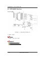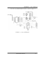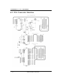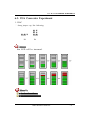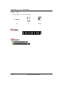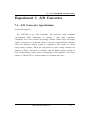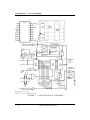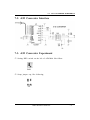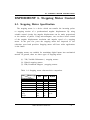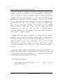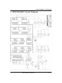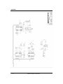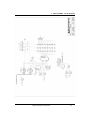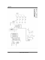
1
MDA-Win8086 MANUAL An Integrated Development Environment kit User's Manual Documentation Version 10.0 Midas Engineering co., ltd. ACE Techno-Tower Ⅴ#906, 197-22, Guro-Dong Guro-Gu, Seoul, KOREA Tel. +82-2-2109-5964~7 Fax. +82-2-2109-5968 www.midaseng.com E_mail. [email protected] ◆ PREFACE ◆ The first 50 years of the 20th century witnessed the invention of the internal combustion engine, which greatly extended the physical strength of the human body. In the second half of the century, the birth of the microprocessor further extended our mental capabilities. Applications of this amazing product in various industries have introduced so much impact on our lives, hence, it is called the second industrial Revolution. Microcomputers represent a total change in designing systems. Both industrial and academic institutions are active in the development and search for new applications for microcomputers. This book is designed to be used in conjunction with the "multi tech" MDA-Win8086 Microcomputers as part of a one-year laboratory class on microcomputers. With the aid of this book, students will be able to learn the fundamentals of microcomputers, from basic CPU instructions to practical applications. The first part of this book is an introduction to the basic concepts of microcomputer programming. It lays the foundation for year studies, the second part of this book is the microcomputer hardware, such as , input/output, interrupt, timer and counter experiment, and experiments using microcomputer instructions, such as, data transfers, arithmetic and logic operations, jump and subroutine and memory address allocation in simple program. Experiments involving more complicated arithmetic operations, such as, binary to decimal conversion, decimal to binary conversion, multiplication, division are presented. There are various experiments in this book which are designed to familiarize the student with the fundamentals of input/output programming. These programs are centered around the keyboard and display. These experiments establish the foundation for later experiments involving a simple monitor program, which leads to more complicated MDA-Win8086 programs. PART I : MDA-Win8086 USER'S MANUAL TABLE OF CONTENTS 1. MDA-Win8086 SYSTEM CONFIGURATION ············································· 1 2. OPERATION INTRODUCTION ···································································· 5 2-1. FUNCTION OF KEYS ······························································································ 5 2-2. BASIC OPERATION ································································································· 6 3. EXAMPLE PROGRAM ················································································ 13 4. Serial Monitor ································································································ 21 4-1. How to setup the serial monitor ············································································ 21 4-2. How to connect MDA-Win8086 to your PC ························································ 22 4-3. MDA-WinIDE8086 Installation ················································································ 23 4-4. Tutorial ······················································································································· 24 4-4-1. Launching MDA-WinIDE8086 ······································································· 24 4-4-2. About MDA-WinIDE8086 ·············································································· 25 4-4-3. Assembling and Compiling the source ························································· 29 4-4-4. Troubleshooting ·································································································· 30 4-4-5. Port setting ········································································································· 30 4-4-6. Download and execute the source file ··························································· 31 4-4-7. Other Serial monitor command ········································································ 32 5. 8086 INTERRUPT SYSTEM ······································································· 39 5-1. 5-2. 5-3. 5-4. PREDEFINED INTERRUPTS (0 TO 4) ······························································· 41 INTERRUPT EXPERIMENT ··················································································· 42 USER-DEFINED SOFTWARE INTERRUPTS ····················································· 43 8259A INTERRUPT CONTROL ············································································ 45 6. 8253 INTERFACE ························································································· 46 PART II : MDA-Win8086 EXPERIMENTS (SOFTWARE/HARDWARE) TABLE OF CONTENTS Experiment 1. 8255A Interface ········································································· 48 1-1. 7-Segment ··················································································································· 49 1-2. LED ···························································································································· 49 Experiment 2. Dot-Matrix LED ········································································ 50 2-1. Dot-Matrix LED Display ·························································································· 50 2-2. Dot-Matrix LED Interface ························································································ 51 2-3. SPEAKER Interface ·································································································· 57 Experiment 3. 8251A Interface ········································································· 59 Experiment 4. LCD Display ·············································································· 62 4-1. LCD ···························································································································· 62 4-2. LCD Interface ·········································································································· 66 Experiment 5. Keyboard Interface ···································································· 68 5-1. Keyboard Interface ···································································································· 68 EXPERIMENT 6. D/A CONVERTER ····························································· 71 6-1. D/A Converter Specification ···················································································· 71 6-2. D/A Converter Interface ··························································································· 73 6-3. D/A Converter Experiment ······················································································ 74 Experiment 7. A/D Converter ··········································································· 76 7-1. A/D Converter Specification ·················································································· 76 7-2. A/D Converter Interface ························································································· 78 7-3. A/D Converter Experiment ···················································································· 78 EXPERIMENT 8. Stepping Motor Control ····················································· 80 8-1. Stepping Motor Specification ················································································· 80 8-2. Stepping Motor Interface ························································································ 83 8-3. Stepping Motor Experiment ··················································································· 84 APPENDIX MDA-Win8086 APPENDIX TABLE OF CONTENTS 1. MDA-Win8086 Circuit Diagram ································································ 86 2. MDA-Win8086 External Connector ····························································· 92 3. 8086 Pin Configuration. ·············································································· 95 4. 8086 Instruction Set Summary. ·································································· 96 2-1 FUNCTION OF KEYS 1. MDA-Win8086 SYSTEM CONFIGURATION FIGURE 1. MDA-Win8086 SYSTEM CONFIGURATION MDA-Win8086 MANUAL - 1 - 1. MDA-Win8086 SYSTEM CONFIGURATION ☞ The function of IC's at Figure 1. ① CPU(Central processing unit) : Using Intel 8086, Using 14.7456㎒. ② ROM(Read Only Memory) : It has program to control user's key input, LCD display, user's program. 64K Byte, it has data communication program. Range of ROM Address is F0000H~FFFFFH. ③ SRAM(Static Random Access Memory) : Input user's program & data. Address of memory is 00000H~0FFFFH, totally 64K Byte. ④ DISPLAY : Text LCD Module, 16(Characters)×2(Lines) ⑤ KEYBOARD : It is used to input machine language. There are 16 hexadecimal keys and 8 function keys. ⑥ SPEAKER : Sound test. ⑦ RS-232C : Serial communication with IBM compatible PC. ⑧ DOT MATRIX LED : To understand & test the dot matrix structure and principle of display. It is interfaced to 8255A(PPI). ⑨ A/D CONVERTER : ADC0804 to convert the analog signal to digital signal. ⑩ D/A CONVERTER : DAC0800 (8-bits D/A converter) to convert the digital signal to the analog signal and to control the level meter. ⑪ STEPPING MOTOR INTERFACE ⑫ POWER : AC - 2 - : Stepping motor driver circuit is designed. 110~220V, DC +5V 3A, +12V 1A, -12V 0.5A SMPS. MDA-Win8086 MANUAL 2-1 FUNCTION OF KEYS > MDA-Win8086 ADDRESS MAP ① Memory map ADDRESS MEMORY 00000H ~ 0FFFFH RAM PROGRAM & DATA MEMORY F0000H ~ FFFFFH ROM MONITOR ROM 10000H ~ EFFFFH DESCRIPTION USER'S RANGE ② I/O address map ADDRESS I/O PORT 00H ~ 07H LCD & KEYBOARD LCD Display 00H : INSTRUCTION REGISTER 02H : STATUS REGISTER 04H : DATA REGISTER KEYBOARD 01H : KEYBOARD REGISTER (Only read) 01H : KEYBOARD FLAG (Only write) 08H ~ 0FH 8251 / 8253 8251(Using to data communication) 08H : DATA REGISTER 0AH : INSTRUCTION / STATUS REGISTER 8253(TIMER/COUNTER) 09H : TIMER 0 REGISTER 0BH : TIMER 1 REGISTER 0DH : TIMER 2 REGISTER 0FH : CONTROL REGISTER 10H ~ 17H 8259/SPEAKER 18H ~ 1FH 8255A-CS1/ 8255A-CS2 DESCRIPTION 8259(Interrupt controller) 10H : COMMAND REGISTER 12H : DATA REGISTER 11H : SPEAKER SPEAKER 8255A-CS1(DOT & ADC INTERFACE) 18H : A PORT DATA REGISTER 1AH : B PORT DATA REGISTER 1CH : C PORT CONTROL REGISTER 8255-CS2(LED & STEPPING MOTOR) 19H : A PORT DATA REGISTER 1BH : B PORT DATA REGISTER 1DH : C PORT CONTROL REGISTER 1FH : CONTROL REGISTER 20H ~ 2FH I/O EXTEND CONNECTOR 30H ~ FFH USER'S RANGE MDA-Win8086 MANUAL - 3 - 2. OPERATION INTRODUCTION 2. OPERATION INTRODUCTION 2‐1. FUNCTION OF KEYS MDA-Win8086 has high performance 64K-byte monitor program. It is designed for easy function. After power is on , the monitor program begins to work. In addition to all the key function the monitor has a memory checking routine. The following is a simple description of the key functions. FUNCTION KEY DATA KEY RES MON GO STP C D E F + REG 8 9 A B - DA 4 5 6 7 : AD 0 1 2 3 RES system reset STP execute user's program, a single step AD set memory address GO go to user's program or execute monitor functions DA Update segment & Offset. and input data to memory MON Immediately break user's program and Non makable interrupt. : Offset. REG Register Display. + Segment & Offset +1 increment. Register display increment. - Segment & Offset -1 increment. Register display decrement. - 4 - MDA-Win8086 MANUAL 2-2. BASIC OPERATION 2‐2. BASIC OPERATION On a power-up, following message will be displayed on a LCD. MDE8086 Kit V9.5 Midas 2109-5964/5 Or Serial monitor ! Midas 2109-5964/5 Figure 1-1. Figure 1-2. To select the Machine Code and Serial monitor mode with P1 switch. SELECT MODE SELECT MODE G +5 KIT PC G +5 KIT PC ☞ P1 P1 Machine Code ※ RES Serial monitor System Reset Key Whenever RES is pressed, the display becomes FIGURE 1-1 or FIGURE 1-2. MDA-Win8086 MANUAL - 5 - 2. OPERATION INTRODUCTION ※ AD , : HEXA-DIGIT KEY : Substitute to segment & offset , address EXAMPLE 1 ) Check the contents in memory. KEY AD LCD Seg. 0000 0set 1000 data FF Input data offset [The contents of memory 0000:1000 ( It may be different)] F Seg. 0set data 000F 1000 FF Input data offset [The contents of memory 000F:1000 ( It may be different)] 0 Seg. 0set data 00F0 1000 FF Input data offset [The contents of memory 00F0:1000 ( It may be different)] 0 Seg. 0F00 0set 1000 data FF Input data offset [The contents of memory 0F00:1000 ( It may be different)] - 6 - MDA-Win8086 MANUAL 2-2. BASIC OPERATION Seg. F000 0 0set 1000 data FF Input data offset [The contents of memory F000:1000 ( It may be different)] : Seg. 0set data F000 1000 FF segment offset [The contents of memory F000:1000 ( It may be different)] Seg. F000 0 0set 0000 data FF Input data offset [The contents of memory F000:0000] ※ AD , + , - KEY : Increment and decrement to segment & offset address. When the power is on or press the RES key, following message will be displayed on LCD. MDE8086 Kit V9.5 Midas 2109-5964/5 When the AD key is pressed, MDA-Win8086 MANUAL - 7 - 2. OPERATION INTRODUCTION KEY LCD AD Seg. 0set data 0000 1000 FF Input data offset [The contents of memory 0000:1000 ( It may be different)] Seg. 0001 + 0set 1000 data FF segment +1 increment [The contents of memory 0001:1000 ( It may be different)] Seg. 0002 + 0set 1000 data FF segment +1 increment [The contents of memory 0002:1000( It may be different)] Seg. 0001 - 0set 1000 data FF segment -1 increment [The contents of memory 0001:1000 ( It may be different)] ※ AD , : , HEXA-DIGIT KEY : Update to memory contents. - 8 - MDA-Win8086 MANUAL 2-2. BASIC OPERATION EXAMPLE 2 ) Let's store the following like to 01000H ~ 01003H contents. < ADDRESS DATA> 01000 AB 01001 CD 01002 EF 01003 34 KEY LCD RES MDE8086 Kit V9.5 Midas 2109-5964/5 AD Seg. 0set data 0000 1000 FF segment offset [The contents of memory 0000:1000] DA Seg. 0set data 0000 1000 FF segment offset [The contents of memory 0000:1000 (It may be different)] A + B Seg. 0000 0set 1000 data AB Seg. 0000 0set 1001 data FF Offset increment MDA-Win8086 MANUAL - 9 - 2. OPERATION INTRODUCTION C D + Seg. 0set data 0000 1001 CD Seg. 0set data 0000 1002 FF Offset increment E F + Seg. 0000 0set 1002 data EF Seg. 0000 0set 1003 data FF Offset increment 3 4 + Seg. 0set data 0000 1003 34 Seg. 0set data 0000 1004 FF Offset increment ※ REG , KEY RES + , - KEY : Display to register contents. LCD AX=0000 BX=0000 CX=0000 DX=0000 Current register contents. + - 10 - SP=0540 SI=0000 BP=0000 DI=0000 MDA-Win8086 MANUAL 2-2. BASIC OPERATION + + DS=0000 SS=0000 IP=1000 ES=0000 CS=0000 FL=0000 =.................... ↓ Current register contents. - - DS=0000 ES=0000 SS=0000 CS=0000 SP=0540 SI=0000 BP=0000 DI=0000 MDA-Win8086 MANUAL - 11 - 3. EXAMPLE PROGRAM 3. EXAMPLE PROGRAM ♣ STP Single Step Store a following program in RAM and execute it by single steps. ADDRESS MACHINE CODE MNEMONIC 1000 B8 0000 MOV 1003 9E SAHF 1004 05 8947 ADD AX, 4789H 1007 15 8864 ADC AX, 6488H 100A 04 88 ADD AL, 88H 100C 80 D4 33 ADC AX ,0 AH, 33H ; 100F 2D 6735 SUB AX, 3567H 1012 1D 0080 SBB AX, 8000H 1015 2C 45 SUB AL, 45H 1017 80 DC 78 SBB AH, 78H ; 101A B0 FF MOV AL, FFH 101C FE C0 INC AL 101E FE C8 DEC AL 1020 98 CBW 1021 F6 D8 NEG AL ; 1023 B0 F0 MOV AL, F0H 1025 B3 11 MOV BL, 11H 1027 F6 E3 MUL BL ; - 12 - 1029 B8 00F0 MOV AX, F000H 102C BB 3412 MOV BX, 1234H 102F F7 EB IMUL MDA-Win8086 MANUAL BX 3. EXAMPLE PROGRAM ; 1031 B8 F000 MOV AX, 00F0H 1034 B3 10 MOV BL, 10H 1036 F6 F3 DIV BL ; 1038 BA FFFF MOV 103B B8 FFFF MOV AX, -1 103E BB 0100 MOV BX, 1 1041 F7 FB IDIV BX DX, -1 ; 1043 CC INT 3 ① Again, using with machine code input program from 1000H. ② It is valid only when the display is in current Flag form. Pressing "STP" key causes the CPU to execute one instruction point according to the user's PC. After execution, the monitor regains control and displays the new PC and its contents. The user may examine and modify registers and memory contents after each step. KEY LCD RES MDE8086 Kit V9.5 Midas 2109-5964/5 AD Seg. 0set data 0000 1000 B8 segment offset [The contents of memory 0000:1000] MDA-Win8086 MANUAL - 13 - 3. EXAMPLE PROGRAM 1) MOV AX, 0 (Next address) IP=1003 =...t...... STP FL=0100 Current Flag content (It means single step) Result verify ! AX=0000 CX=0000 + BX=0000 DX=0000 Current Register content 2) SHAF (Next address) IP=1004 =...t...... STP 3) ADD AX, 4789H (Next address) IP=1007 STP FL=0100 FL=0100 =...t...... Result verify ! AX=4789 CX=0000 + 4) ADC AX, 6488H + - 14 - (Next address) IP=100A FL=0994 =o..ts.ap. (over flag set, alternate carry set, sign flag set, parity flag set) STP Result verify BX=0000 DX=0000 ! AX=AC11 CX=0000 BX=0000 DX=0000 MDA-Win8086 MANUAL 3. EXAMPLE PROGRAM 5) ADD AL, 88H (Next address) IP=100C STP FL=0184 =o..ts..p. (sign flag set, parity flag set) Result verify ! AX=AC99 CX=0000 + 6) ADC AH, 33H (Next address) IP=100F =...ts.... STP Result verify AX=DF99 CX=0000 7) SUB AX, 3567H STP 8) SBB AX, 8000H STP + 9) SUB AL, 45H STP BX=0000 DX=0000 (Next address) IP=1012 =...ts.... FL=0180 AX=AA32 CX=0000 BX=0000 DX=0000 ! + Result verify FL=0180 ! + Result verify BX=0000 DX=0000 (Next address) IP=1015 =...t..... FL=0100 AX=2A32 CX=0000 BX=0000 DX=0000 ! (Next address) IP=1017 =...ts.apc MDA-Win8086 MANUAL FL=0195 - 15 - 3. EXAMPLE PROGRAM Result verify ! AX=2AED CX=0000 + 10) SBB AH, 78H Result verify (Next address) IP=101A =...ts..pc STP BX=0000 DX=0000 FL=0185 ! AX=B1ED + CX=0000 11) MOV AL, FFH DX=0000 (Next address) IP=101C STP BX=0000 FL=0185 =...ts..pc Result verify ! AX=B1FF CX=0000 + 12) INC AL BX=0000 DX=0000 (Next address) IP=101E STP FL=0155 =...t.zapc Result verify ! AX=B100 CX=0000 + 13) DEC AL (Next address) IP=1020 =...ts.apc STP Result verify 14) CBW STP FL=0195 ! AX=B1FF + BX=0000 DX=0000 CX=0000 BX=0000 DX=0000 (Next address) IP=1021 FL=0195 =...ts.apc - 16 - MDA-Win8086 MANUAL 3. EXAMPLE PROGRAM Result verify ! AX=FFFF CX=0000 + 15) NEG AL (Next address) IP=1023 =...t..a.c STP Result verify BX=0000 DX=0000 FL=0111 ! + 16) MOV AL, F0H AX=FF01 BX=0000 CX=0000 DX=0000 (Next address) IP=1025 STP FL=0111 =...t..a.c Result verify ! AX=FFF0 CX=0000 + 17) MOV BL, 11H (Next address) IP=1027 STP BX=0000 DX=0000 FL=0111 =...t..a.c Result verify ! AX=FFF0 CX=0000 + 18) MUL BL BX=0011 DX=0000 (Next address) IP=1029 STP FL=0905 =o..t...pc Result verify ! + 19) MOV AX, F000H STP AX=0FF0 CX=0000 BX=0011 DX=0000 (Next address) IP=102C =o..t...pc MDA-Win8086 MANUAL FL=0905 - 17 - 3. EXAMPLE PROGRAM Result verify ! AX=F000 CX=0000 + 20) MOV BX, 1234H Result verify (Next address) IP=102F =o..t...pc STP BX=0011 DX=0000 FL=0905 ! + 21) IMUL BX AX=F000 BX=1234 CX=0000 DX=0000 (Next address) IP=1031 STP FL=0985 =o..ts..pc Result verify ! AX=C000 CX=0000 + 22) MOV AX, 00F0H (Next address) IP=1034 STP BX=1234 DX=FEDC FL=0985 =o..ts..pc Result verify ! AX=00F0 CX=0000 + 23) MOV BL, 10H STP Result verify + 24) DIV BL STP BX=1234 DX=FEDC (Next address) IP=1036 =o..ts..pc FL=0985 AX=00F0 CX=0000 BX=1210 DX=FEDC ! (Next address) IP=1038 FL=0145 =...t.z.pc - 18 - MDA-Win8086 MANUAL 3. EXAMPLE PROGRAM Result verify ! AX=000F CX=0000 + 25) MOV DX, -1 BX=1210 DX=FEDC (Next address) IP=103B STP FL=0145 =...t.z.pc Result verify ! + 26) MOV AX,-1 CX=0000 DX=FFFF IP=103E =...t.z.pc FL=0145 AX=FFFF CX=0000 BX=1210 DX=FFFF ! + 27) MOV BX, 1 (Next address) STP Result verify BX=1210 (Next address) STP Result verify AX=000F IP=1041 =...t.z.pc FL=0145 AX=FFFF CX=0000 BX=0001 DX=FFFF ! + 28) IDIV BX (Next address) IP=1043 STP FL=0144 =...t.z.p. Result verify + ! AX=FFFF BX=0001 CX=0000 DX=0000 MDA-Win8086 MANUAL - 19 - 4. SERIAL MONITOR 4. Serial Monitor Serial monitor is the basic monitor program to do data communicate between MDA-Win8086 and your computer. 4‐1. How to setup the serial monitor Adjust the P1 switch as following figure. SELECT MODE G +5 KIT PC P1 Serial monitor - 20 - MDA-Win8086 MANUAL 4-2 How to connect MDA-Win8086 to your PC 4‐2. How to connect MDA‐Win8086 to your PC ① Connect the MDA-Win8086 Kit to a spare serial port on your PC. FIGURE 4-1. PC 25 PIN - MDA-Win8086 9 PIN connection FIGURE 4-2. PC 9 PIN - MDA-Win8086 9 PIN connection MDA-Win8086 MANUAL - 21 - 4. SERIAL MONITOR 4‐3. MDA‐WinIDE8086 Installation ➀ Insert the CD in the CD-ROM driver, and double "SETUP.EXE". ➁ The installation begins. - 22 - MDA-Win8086 MANUAL click the file 4-4 Tutorial 4‐4. Tutorial 4-4-1 Launching MDA-WinIDE8086 Click the Start button in the task bar, then click All Programs and MIDAS ENG. Then click the MDA-WinIDE8086 program icon MDA-Win8086 MANUAL - 23 - 4. SERIAL MONITOR ⑵ The MDA-WinIDE8086 window will be displayed. 4-4-2. About MDA-WinIDE8086 Menu bar Gives access to the MDA-WinIDE8086 menu. - 24 - MDA-Win8086 MANUAL 4-4 Tutorial File menu The File menu provides command s for opening source files, saving and exiting from the MDA-WinIDE8086 window. New Open Save Save As Exit Create empty text file Open a file in text editor Save current text file Save current text file under given name Exit MDA-WinIDE8086 window Edit menu The Edit menu provides command for editing and searching in editor windows. Undo Cut Copy Paste Find Select All Undo last editor action Cut and copy selected text from editor Copy selected text form editor Paste any text form clipboard to the editor Open a find dialog to search through the current source file Select all text at once Work menu Assemble & Link Compile & Link Program Write Assemble and link a source file you are editing Compile and link a source file your are editing Run Start execution of the program Trace Execute one instruction Download a file to MDA-Win8086 Run menu MDA-Win8086 MANUAL - 25 - 4. SERIAL MONITOR Tool bar The tool bar provides button s for the most useful commands on the MDA-WinIDE8086 menus. Button Menu Command New Create empty text file Open Open a file in text editor Save Save current text file Find Open a find dialog Undo Show Line Number Assemble & Link Compile & Link Program write Undo last editor action Show line number Assemble and link a source file you are editing Compile and link a source file you are editing Download an "ABS" file to MDA-Win8086 kit Memory dump Dump memory contents Fill data Move block Run Trace Port setting Fill memory with any data Move memory block The program will be executed Execute one instruction To change the modem's port setting Editor window Source file is displayed in the editor window. The MDA-WinIDE8086 editor automatically recognizes the syntax of C program and Assemble program. - 26 - MDA-Win8086 MANUAL 4-4 Tutorial Terminal window Terminal window is that you can use to connect the MDA-Win8086 kit. MDA-Win8086 MANUAL - 27 - 4. SERIAL MONITOR 4-4-3. Assembling and Compiling the source Click - 28 - / button for assembling/compiling to generate an ABS file. MDA-Win8086 MANUAL 4-4 Tutorial 4-4-4. Troubleshooting The output window lists tool information during the code generation. You may check on error messages to correct syntax errors in your program. 4-4-5. Port setting ⑴ After connect the MDA-Win8086 kit to a spare serial port on your PC, press RESET KEY, then "8086>" prompt will be displayed. If "8086>" prompt is not displayed, click the MDA-Win8086 MANUAL button to setup port. - 29 - 4. SERIAL MONITOR Select the serial port to connected to your PC. (ie. COM1, COM2, COM3 or COM4 ) BPS : 9600, Parity : None, Stop bits : 1 Press MDA-Win8086 RESET KEY again then "8086>" prompt will be displayed. 4-4-6. Download and execute the source file 1. Download Click button or select Program Write from the Work menu. You can also type 'L' and "Enter" key on Terminal window, then press "Page Up" button from your keyboard. - 30 - MDA-Win8086 MANUAL 4-4. Tutorial 2. Execute ⑴ Run Click button or select "Run" from the Run menu. You can also type 'G' and "Enter" key on Terminal window. The Run command in the work menu starts execution of the program. The program will be executed until it is stopped by pressing RESET KEY. ⑵ Trace Click button or select "Trace" from the Run menu. You can also type 'T' and "Enter" key on Terminal window. The Trace command in the work menu executes one instruction. 4-4-7. Other serial monitor command User can only use command which stored at serial monitor. Serial monitor can execute to command when user type command and then CR(carriage return) key. MDA-Win8086 MANUAL - 31 - 5. Serial monitor command ⌘ If there is no any command at serial monitor, error message will be displayed with bell sound and serial monitor prompt will be displayed again. ** 8086 Monitor 9.5 ** ** Midas 2109-9964/5 ** 8086 > Carriage Return 8086 >? HELP...............................................................................:COMMAND E segment : offset.........................................................: Enter Data To Memory D segment : offset length............................................: Dump Memory Contents R [register name]...........................................................: Register Display & Change M address1, length, address2.......................................: Move Memory From 1 to 2 F address, length, data..................................................: Fill Memory With Any Data L Return key..................................................................: Program Down Load G segment : offset..........................................................: Execute Program T.......................................................................................: Program 1 step execute Memory modify command. Segment Offset 8086 >E 0000:1000 0000:1000 FF ? 11 0000:1001 FF ? 22 0000:1002 FF ? 33 0000:1003 FF ? 44 0000:1004 FF ? 55 0000:1005 FF ? / (Offset decrement) 0000:1004 55 ? / Memory display command. - 32 - MDA-Win8086 MANUAL 4-4. Tutorial Click button, then memory dump window will be displayed. Enter Segment, Offset, and Length, then click "Dump" button. You can also enter the memory dump command on Terminal window. Segment Offset Length 8086 >D 0000:1000 FF 0000:1000 11 22 33 44 55 FF FF FF - FF FF FF FF FF FF FF FF ."3DU......... 0000:1010 FF FF FF FF FF FF FF FF - FF FF FF FF FF FF FF FF ................... 0000:1020 FF FF FF FF FF FF FF FF - FF FF FF FF FF FF FF FF ................... 0000:1030 FF FF FF FF FF FF FF FF - FF FF FF FF FF FF FF FF ................... 0000:1040 FF FF FF FF FF FF FF FF - FF FF FF FF FF FF FF FF ................... 0000:1050 FF FF FF FF FF FF FF FF - FF FF FF FF FF FF FF FF ................... 0000:1060 FF FF FF FF FF FF FF FF - FF FF FF FF FF FF FF FF ................... 0000:1070 FF FF FF FF FF FF FF FF - FF FF FF FF FF FF FF FF ................... 0000:1080 FF FF FF FF FF FF FF FF - FF FF FF FF FF FF FF FF ................... 0000:1090 FF FF FF FF FF FF FF FF - FF FF FF FF FF FF FF FF ................... 0000:10A0 FF FF FF FF FF FF FF FF - FF FF FF FF FF FF FF FF ................... 0000:10B0 FF FF FF FF FF FF FF FF - FF FF FF FF FF FF FF FF ................... 0000:10C0 FF FF FF FF FF FF FF FF - FF FF FF FF FF FF FF FF ................... 0000:10D0 FF FF FF FF FF FF FF FF - FF FF FF FF FF FF FF FF ................... 0000:10E0 FF FF FF FF FF FF FF FF - FF FF FF FF FF FF FF FF ................... 0000:10F0 FF FF FF FF FF FF FF FF - FF FF FF FF FF FF FF FF ................... 8086 > Display the ASCII code to data MDA-Win8086 MANUAL - 33 - 4. SERIAL MONITOR Fill certain data in memory. Click button, then Fill Data window will be displayed. Enter Segment, Offset, Length, and Data, then click "Fill" button. You can also enter the Fill Data command on Terminal window. Segment Offset Length Data 8086 >F 0000:1000 FF 1234 Verify 8086 >D 0000:1000 FF 0000:1000 12 34 12 34 12 34 12 34 - 12 34 12 34 12 34 12 34 .4.4.4.4.4.4.4.4 0000:1010 12 34 12 34 12 34 12 34 - 12 34 12 34 12 34 12 34 .4.4.4.4.4.4.4.4 0000:1020 12 34 12 34 12 34 12 34 - 12 34 12 34 12 34 12 34 .4.4.4.4.4.4.4.4 0000:1030 12 34 12 34 12 34 12 34 - 12 34 12 34 12 34 12 34 .4.4.4.4.4.4.4.4 0000:1040 12 34 12 34 12 34 12 34 - 12 34 12 34 12 34 12 34 .4.4.4.4.4.4.4.4 0000:1050 12 34 12 34 12 34 12 34 - 12 34 12 34 12 34 12 34 .4.4.4.4.4.4.4.4 0000:1060 12 34 12 34 12 34 12 34 - 12 34 12 34 12 34 12 34 .4.4.4.4.4.4.4.4 0000:1070 12 34 12 34 12 34 12 34 - 12 34 12 34 12 34 12 34 .4.4.4.4.4.4.4.4 0000:1080 12 34 12 34 12 34 12 34 - 12 34 12 34 12 34 12 34 .4.4.4.4.4.4.4.4 0000:1090 12 34 12 34 12 34 12 34 - 12 34 12 34 12 34 12 34 .4.4.4.4.4.4.4.4 0000:10A0 12 34 12 34 12 34 12 34 - 12 34 12 34 12 34 12 34 .4.4.4.4.4.4.4.4 0000:10B0 12 34 12 34 12 34 12 34 - 12 34 12 34 12 34 12 34 .4.4.4.4.4.4.4.4 0000:10C0 12 34 12 34 12 34 12 34 - 12 34 12 34 12 34 12 34 .4.4.4.4.4.4.4.4 0000:10D0 12 34 12 34 12 34 12 34 - 12 34 12 34 12 34 12 34 .4.4.4.4.4.4.4.4 0000:10E0 12 34 12 34 12 34 12 34 - 12 34 12 34 12 34 12 34 .4.4.4.4.4.4.4.4 - 34 - MDA-Win8086 MANUAL 4-4. Tutorial 0000:10F0 12 34 12 34 12 34 12 34 - 12 34 12 34 12 34 12 34 .4.4.4.4.4.4.4.4 Block move command. The Block Move command is used to move blocks of memory from one area to another. Click button, then Move window will be displayed. Enter Segment, Offset, Length, and Address, then click "Move" button. You can also enter the Block Move command on Terminal window. Segment Offset Length Data 8086 >M 0000:1000 FF 2000 Resulting ? 8086 >D 0000:2000 0000:2000 12 34 12 34 12 34 12 34 - 12 34 12 34 12 34 12 34 .4.4.4.4.4.4.4.4 0000:2010 12 34 12 34 12 34 12 34 - 12 34 12 34 12 34 12 34 .4.4.4.4.4.4.4.4 0000:2020 12 34 12 34 12 34 12 34 - 12 34 12 34 12 34 12 34 .4.4.4.4.4.4.4.4 0000:2030 12 34 12 34 12 34 12 34 - 12 34 12 34 12 34 12 34 .4.4.4.4.4.4.4.4 0000:2040 12 34 12 34 12 34 12 34 - 12 34 12 34 12 34 12 34 .4.4.4.4.4.4.4.4 0000:2050 12 34 12 34 12 34 12 34 - 12 34 12 34 12 34 12 34 .4.4.4.4.4.4.4.4 0000:2060 12 34 12 34 12 34 12 34 - 12 34 12 34 12 34 12 34 .4.4.4.4.4.4.4.4 0000:2070 12 34 12 34 12 34 12 34 - 12 34 12 34 12 34 12 34 .4.4.4.4.4.4.4.4 0000:2080 12 34 12 34 12 34 12 34 - 12 34 12 34 12 34 12 34 .4.4.4.4.4.4.4.4 0000:2090 12 34 12 34 12 34 12 34 - 12 34 12 34 12 34 12 34 .4.4.4.4.4.4.4.4 MDA-Win8086 MANUAL - 35 - 4. SERIAL MONITOR 0000:20A0 12 34 12 34 12 34 12 34 - 12 34 12 34 12 34 12 34 .4.4.4.4.4.4.4.4 0000:20B0 12 34 12 34 12 34 12 34 - 12 34 12 34 12 34 12 34 .4.4.4.4.4.4.4.4 0000:20C0 12 34 12 34 12 34 12 34 - 12 34 12 34 12 34 12 34 .4.4.4.4.4.4.4.4 0000:20D0 12 34 12 34 12 34 12 34 - 12 34 12 34 12 34 12 34 .4.4.4.4.4.4.4.4 0000:20E0 12 34 12 34 12 34 12 34 - 12 34 12 34 12 34 12 34 .4.4.4.4.4.4.4.4 0000:20F0 12 34 12 34 12 34 12 34 - 12 34 12 34 12 34 12 34 .4.4.4.4.4.4.4.4 Display Registers command. The R command is used to display the i8086 processor registers. 8086 >R AX=0000 SP=0540 DS=0000 IP=1000 BX=0000 BP=0000 ES=0000 FL=0000 CX=0000 SI=0000 SS=0000 = . . . . DX=0000 DI=0000 CS=0000 . . . . . CX=7788 SI=0000 SS=0000 = . . . . DX=1111 DI=0000 CS=0000 . . . . . Individual register change 8086 >R AX AX=0000 1234 BX=0000 4567 CX=0000 7788 DX=0000 1111 SP=0540 Result 8086 >R AX=1234 SP=0540 DS=0000 IP=1000 BX=4567 BP=0000 ES=0000 FL=0000 8086 >R IP IP=1000 8086 > - 36 - MDA-Win8086 MANUAL 5. 8086 INTERRUPT SYSTEM 5. 8086 INTERRUPT SYSTEM The 8086 interrupts can be classified into three types. These are 1. Predefined interrupts 2. User-defined software interrupts 3. User-defined hardware interrupts The interrupt vector address for all the 8086 interrupts are determined from a table stored in locations 00000H through 003FFH. The starting addresses for the service routines for the interrupts are obtained by the 8086 using this table. Four bytes of the table are assigned to each interrupt: two bytes for IP and two bytes for CS. The table may contain up to 256 8-bit vectors. If fewer than 256 interrupts are defined in the system, the user need only provide enough memory for the interrupt pointer table for obtaining the defined interrupts. The interrupt address vector (contents of IP and CS) for all the interrupts of the 8086 assigns every interrupt a type code for identifying the interrupt. There are 256 type codes associated with 256 table entires. Each entry consists of two addresses, one for storing the IP contents and the other for storing the CS contents. Each 8086 interrupt physical address vector is 20 bits wide and is computed from the 16-bit contents of IP and CS. For obtaining an interrupt address vector, the 8086 calculates two addresses in the pointer table where IP and CS are stored for a particular interrupt type. For example, for the interrupt type nn(instruction INT nn), the table address for IP=4×nn and the table address for CS=4×nn+2. For servicing the 8086's nonmaskable interrupt (NMI pin), the 8086 assigns the type code 2 to this interrupt. The 8086 automatically executes the INT2 instruction internally to obtain the interrupt address vector as follows: MDA-Win8086 MANUAL - 37 - 5. 8086 INTERRUPT SYSTEM Address for IP = 4 × 2 = 00008H Address for CS = 4 × 2 + 2 = 0000AH The 8086 loads the values of IP and CS from the 20-bit physical address 00008H and 0000AH in the pointer table. The user must store the desired 16-bit values of IP and CS in these locations. Similarly, the IP and CS values for other interrupts are calculated. The 8086 interrupt pointer table layout is shown in table 6-1. Interrupt type code ↓ 0 1 20-bit Memory Address ↓ IP CS IP CS 2 ․ ․ ․ ․ ․ ․ 255 IP CS 00000H 00002H 00004H 00006H 00008H 0000AH ․ ․ ․ ․ ․ ․ 003FEH 00400H TABLE 6-1. 8086 INTERRUPT POINTER TABLE In response to an interrupt, the 8086 pushes flags, CS, and IP onto the stack, clears TF and IF flags, and then loads IP and CS from the pointer table using the type code. Interrupt service routine should be terminated with the IRET( Interrupt Return) instruction which pops the top three stack words into IP, CS, and flags, thus returning to the right place in the main program. The 256 interrupt type codes are assigned as follows; - 38 - MDA-Win8086 MANUAL 5-1. PREDEFINED INTERRUPTS (0 TO 4) ▶ Types 0 to 4 are for the predefined interrupts. ▶ Types 5 to 31 are reserved by intel for future use. ▶ Types 32 to 255 are acailiable for maskable interrupts. 5‐1. PREDEFINED INTERRUPTS (0 TO 4) The predefined interrupts include DIVISION ZERO (type 0), SINGLE STEP (type 1), NONMASKABLE INTERRUPT pin(type 2), BREAKPOINT INTERRUPT (type 3), and INTERRUPT ON OVERFLOW (type 4). The user must provide the desired IP and CS values in the interrupt pointer table. The user may also imitate these interrupts through hardware or software. If a predefined interrupt is not used in a system, the user may assign some other function to the associated type. The 8086 is automatically interrupted whenever a division by zero is attempted. This interrupt is nonmaskable and is implemented by intel as part of the execution of the divide instruction. When the TF(TRAP flag) is set by an instruction, the 8086 goes into the single step mode. The TF can be cleared to zero as follows; PUSHF ; Save flags MOV BP, SP ; Move [SP] AND [BP+0], 0FEFFH ; Clear TF [BP] POPF Note that in the above [BP+0] rather than [BP] is used since BP cannot be used without displacement. Now, to set TF, the AND instruction in the above should be replaced by OR [BP+0], 0100H. Once TF is set to one, the 8086 automatically generates a TYPE 1 interrupt after execution of each instruction. The user can write a service routine at the interrupt address vector to display memory locations and/or register to debug a program. Single step is nonmaskable and cannot be enabled by STI (enable interrupt) or CLI (disable interrupt) instruction. The nonmaskable interrupt is initiated via the 8086 NMI pin. MDA-Win8086 MANUAL - 39 - 5. 8086 INTERRUPT SYSTEM It is edge triggered (LOW to HIGH) and must be active for two clock cycles to guarantee recognition. It is normally used for catastrophic failures such as power failure. The 8086 obtains the interrupt vector address by automatically executing the INT2(type 2) instruction internally. Type 3 interrupt is used for breakpoint and is nonmaskable. The user inserts the one-byte instruction INT3 into a program by replacing an instruction. Break points are useful for program debugging. The INTERRUPT ON OVERFLOW is a type 4 interrupt. This interrupt occurs if the overflow flag(OF) is set and the INT0 instruction is expected. The overflow flag is affected, for example, after execution of signed arithmetic such as MULS (signed multiplication) instruction. The user can execute the INTO instruction after the MULS. If there is an overflow, an error service routine written by the user at the type 4 interrupt address vector is executed. 5‐2. INTERRUPT EXPERIMENT ◎ 1. Internal Interrupt : Division by zero (type 0) < Sample Program 5-1. Internal Interrupt : Division by zero (type 0) ; FILENAME : INT1.ASM ; PROCESSOR : I8086 ADDRESS 0000 MACHINE CODE MNEMONIC CODE SEGMENT ASSUME CS:CODE,DS:CODE,ES:CODE,SS:CODE ; 1000 ORG 1000H 1000 B8 1234 MOV AX,1234H 1003 B3 00 MOV BL,00H 1005 F6 F3 DIV BL 1007 90 NOP 1008 90 NOP - 40 - MDA-Win8086 MANUAL 5-2. INTERRUPT EXPERIMENT 1009 CC INT 3 ; 100A CODE ENDS END < Sample Program 5-2. Overflow Interrupt > ; FILENAME : INT2.ASM ; PROCESSOR : I8086 ADDRESS 0000 MACHINE CODE MNEMONIC CODE SEGMENT ASSUME CS:CODE,DS:CODE,ES:CODE,SS:CODE ; 1000 ORG 1000H 1000 B8 1234 MOV AX,1234H 1003 BB 7234 MOV BX,7234H 1006 03 C3 ADD AX,BX 1008 CE INTO 1009 90 NOP 100A 90 NOP 100B CC INT 3 ; 100C CODE ENDS END 5‐3. USER‐DEFINED SOFTWARE INTERRUPTS The user can generate an interrupt by executing a two-byte interrupt instruction INT nn. The INT nn instruction is not maskable by the interrupt enable flag(IF). The INT nn instruction can be used to test an interrupt service routine for external interrupts. Type codes 0 to 255 can be used. If predefined interrupt is not used in a system, the associated type code can be utilized with the INT nn instruction to generate software(internal) interrupts. MDA-Win8086 MANUAL - 41 - 5. 8086 INTERRUPT SYSTEM < Sample Program 5-3. Software Interrupt > ; FILENAME : INT3.ASM ; PROCESSOR : I8086 ADDRESS 0000 MACHINE CODE MNEMONIC CODE SEGMENT ASSUME CS:CODE,DS:CODE,ES:CODE,SS:CODE ; = 0084 V_TAB EQU 21H*4 = 0000 SEG_D EQU 0000H ; 1000 ORG 1000H 1000 B8 0000 MOV AX,SEG_D 1003 8E D8 MOV DS,AX 1005 BB 0084 MOV BX,V_TAB 1008 B8 101F R MOV AX,OFFSET INT_SER 100B 89 07 MOV WORD PTR [BX],AX ; 100D 43 INC BX 100E 43 INC BX ; 100F BA 0000 MOV DX,0 1012 89 17 MOV WORD PTR [BX],DX ; 1014 B8 1234 MOV AX,1234H 1017 BB 6789 MOV BX,6789H 101A CD 21 INT 21H 101C 90 NOP 101D 90 NOP 101E CC INT 3 ; 101F 03 C3 1021 CF INT_SER: ADD AX,BX IRET ; - 42 - MDA-Win8086 MANUAL 5-4. 8259A INTERRUPT CONTROL 1022 CODE ENDS END 5‐4. 8259A INTERRUPT CONTROL The Intel 8259A Programmable interrupt controller handes up to eight sectored priority interrupts for the CPU. It is cascadable for up to 64 vectored probity interrupts without additional circuity. It is packaged in a 28-pin DIP, uses NMOS technology and requires a single +5V supply. Circuity is static, requiring no clock input. The 8259A is designed to minimize the software and real time overhead in handling multi-level priority interrupts. It has several modes, permitting optimization for a variety of system requirements. Refer to 8259A data sheet for more detail. The 8259A and MDA-Win8086 interface is shown in Figure 5-1. FIGURE 5-1. 8259A INTERFACE MDA-Win8086 MANUAL - 43 - 1. 8255A INTERFACE 6. 8253 INTERFACE The 8253 is programmable interval timer/counter specifically designed for use with the Intel Micro-computer systems. Its function is that of a gernal purpose, multi-timing element that can be treated as an array of I/O ports in the system software. The 8253 solves one of the most common problems in any microcomputer system, the generation of accurate time delays under software control. Instead of setting up timing loops in systems software, the programmer configures the 8253 to match his requirements, initialize one of the counters of the 8253 with the desired quantity, then upon command the 8253 will count out the delay and interrupt the CPU when it has completed its tasks. It is easy to see that the software overhead is finial and that multiple delays can easily be maintained by assignment of priority levels. Other counter/timer functions that are non-delay in nature but also common to most microcomputers can be implemented with the 8253. ※ ※ ※ ※ ※ ※ Programmable Rate Generator Event Counter Binary Rate Multiplier Real Time Clock Digital One-shot Complex Motor Controller Refer to 8253 data sheet for more detail. - 44 - MDA-Win8086 MANUAL 6. 8253 INTERFACE The 8253 and MDA-Win8086 interface is shown in figure 6-1. FIGURE 6-1. 8253 INTERFACE < Sample Program 6-1. LED ON/OF USING 8253 > ※ Setup jumper cap in P2, like following; ◉ ◉ ◉ ◉ ◉ ◉ ☞ ☞ MDA-Win8086 MANUAL ☞ - 45 - 1. 8255A INTERFACE - 46 - MDA-Win8086 MANUAL 1. 8255A Interface Experiment 1. 8255A Interface FIGURE 1-1. 8255A INTERFACE MDA-Win8086 MANUAL - 47 - 1. 8255A INTERFACE 1‐1. LED ☞ ☞ ☞ 1‐2. 7‐Segment - 48 - ☞ ☞ ☞ ☞ ☞ ☞ ☞ ☞ MDA-Win8086 MANUAL 2-1 Dot-Matrix LED Display Experiment 2. Dot-Matrix LED 2‐1. Dot‐Matrix LED Display General description : The KMD D1288C is 1.26 inch height 3mm diameter and 8 × 8 dot matrix LED displays. The KMD D1288C are dual emitting color type of red, green chips are contained in a dot with milky and white lens color. FIGURE 2-1. DOT MATRIX INTERNAL CIRCUIT DIAGRAM MDA-Win8086 MANUAL - 49 - EXPERIMENT 2. DOT-MATRIX LED 2‐2. Dot‐Matrix LED Interface FIGURE 2-2. DOT-MATRIX LED INTERFACE < Experiment 2-1. Dot-matrix Experiment > - 50 - MDA-Win8086 MANUAL 2-2. DOT-MATRIX LED INTERFACE 1. Matrix ‐ Scroll bottom to top ◯ ◯ ◯ ◯ ◯ ◯ ◯ ● ◯ ◯ ◯ ◯ ◯ ◯ ◯ ● ◯ ◯ ◯ ◯ ◯ ◯ ◯ ● ◯ ◯ ◯ ◯ ◯ ◯ ◯ ● ◯ ◯ ◯ ◯ ◯ ◯ ◯ ● ◯ ◯ ◯ ◯ ◯ ◯ ◯ ● ◯ ◯ ◯ ◯ ◯ ◯ ◯ ● ◯ ◯ ◯ ◯ ◯ ◯ ◯ ● ◯ ◯ ◯ ◯ ● ◯ ◯ ◯ ◯ ◯ ◯ ◯ ● ◯ ◯ ◯ ◯ ◯ ◯ ◯ ● ◯ ◯ ◯ ◯ ◯ ◯ ◯ ● ◯ ◯ ◯ ◯ ◯ ◯ ◯ ● ◯ ◯ ◯ ◯ ◯ ◯ ◯ ● ◯ ◯ ◯ ◯ ◯ ◯ ◯ ● ◯ ◯ ◯ ◯ ◯ ◯ ◯ ● ◯ ◯ ◯ ◯ ● ◯ ◯ ◯ ◯ ◯ ◯ ◯ ● ◯ ◯ ◯ ◯ ◯ ◯ ◯ ● ◯ ◯ ◯ ◯ ◯ ◯ ◯ ● ◯ ◯ ◯ ◯ ◯ ◯ ◯ ● ◯ ◯ ◯ ◯ ◯ ◯ ◯ ● ◯ ◯ ◯ ◯ ◯ ◯ ◯ ● ◯ ◯ ◯ ◯ ◯ ◯ ◯ ● ◯ ◯ ◯ ◯ ◯ ◯ ☞ ◯ ◯ ◯ ◯ ◯ ◯ ● ◯ ◯ ◯ ◯ ◯ ◯ ◯ ● ◯ ◯ ◯ ◯ ◯ ◯ ◯ ● ◯ ◯ ◯ ◯ ◯ ◯ ◯ ● ◯ ◯ ◯ ◯ ◯ ◯ ◯ ● ◯ ◯ ◯ ◯ ◯ ◯ ◯ ● ◯ ◯ ◯ ◯ ◯ ◯ ◯ ● ◯ ◯ ◯ ◯ ◯ ◯ ◯ ● ◯ ☞ ◯ ◯ ◯ ● ◯ ◯ ◯ ◯ ◯ ◯ ◯ ● ◯ ◯ ◯ ◯ ◯ ◯ ◯ ● ◯ ◯ ◯ ◯ ◯ ◯ ◯ ● ◯ ◯ ◯ ◯ ◯ ◯ ◯ ● ◯ ◯ ◯ ◯ ◯ ◯ ◯ ● ◯ ◯ ◯ ◯ ◯ ◯ ◯ ● ◯ ◯ ◯ ◯ ◯ ◯ ◯ ● ◯ ◯ ◯ ◯ ☞ ● ◯ ◯ ◯ ◯ ◯ ◯ ◯ ● ◯ ◯ ◯ ◯ ◯ ◯ ◯ ● ◯ ◯ ◯ ◯ ◯ ◯ ◯ ● ◯ ◯ ◯ ◯ ◯ ◯ ◯ ● ◯ ◯ ◯ ◯ ◯ ◯ ◯ ● ◯ ◯ ◯ ◯ ◯ ◯ ◯ ● ◯ ◯ ◯ ◯ ◯ ◯ ◯ ● ◯ ◯ ◯ ◯ ◯ ◯ ◯ ☞ ◯ ◯ ◯ ◯ ◯ ● ◯ ◯ ◯ ◯ ◯ ◯ ◯ ● ◯ ◯ ◯ ◯ ◯ ◯ ◯ ● ◯ ◯ ◯ ◯ ◯ ◯ ◯ ● ◯ ◯ ◯ ◯ ◯ ◯ ◯ ● ◯ ◯ ◯ ◯ ◯ ◯ ◯ ● ◯ ◯ ◯ ◯ ◯ ◯ ◯ ● ◯ ◯ ◯ ◯ ◯ ◯ ◯ ● ◯ ◯ ☞ ☞ ◯ ◯ ● ◯ ◯ ◯ ◯ ◯ ◯ ◯ ● ◯ ◯ ◯ ◯ ◯ ◯ ◯ ● ◯ ◯ ◯ ◯ ◯ ◯ ◯ ● ◯ ◯ ◯ ◯ ◯ ◯ ◯ ● ◯ ◯ ◯ ◯ ◯ ◯ ◯ ● ◯ ◯ ◯ ◯ ◯ ◯ ◯ ● ◯ ◯ ◯ ◯ ◯ ◯ ◯ ● ◯ ◯ ◯ ◯ ◯ ☞ ※ Setup jumper cap, like following; ◉ ◉ ◉ ◉ ◉ ◉ P6 MDA-Win8086 MANUAL - 51 - EXPERIMENT 2. DOT-MATRIX LED 2. Matrix - Scroll left to right ● ● ● ● ● ● ● ● ◯ ◯ ◯ ◯ ◯ ◯ ◯ ◯ ◯ ◯ ◯ ◯ ◯ ◯ ◯ ◯ ◯ ◯ ◯ ◯ ◯ ◯ ◯ ◯ ◯ ◯ ◯ ◯ ◯ ◯ ◯ ◯ ◯ ◯ ◯ ◯ ◯ ◯ ◯ ◯ ◯ ◯ ◯ ◯ ◯ ◯ ◯ ◯ ◯ ◯ ◯ ◯ ◯ ◯ ◯ ◯ ◯ ◯ ◯ ◯ ◯ ◯ ◯ ◯ ◯ ◯ ◯ ◯ ◯ ◯ ◯ ◯ ◯ ◯ ◯ ◯ ◯ ◯ ◯ ◯ ● ● ● ● ● ● ● ● ◯ ◯ ◯ ◯ ◯ ◯ ◯ ◯ ◯ ◯ ◯ ◯ ◯ ◯ ◯ ◯ ◯ ◯ ◯ ◯ ◯ ◯ ◯ ◯ ◯ ◯ ◯ ◯ ◯ ◯ ◯ ◯ ◯ ◯ ◯ ◯ ◯ ◯ ◯ ◯ ◯ ◯ ◯ ◯ ◯ ◯ ◯ ◯ ◯ ◯ ◯ ◯ ◯ ◯ ◯ ◯ ◯ ◯ ◯ ◯ ◯ ◯ ◯ ◯ ◯ ◯ ◯ ◯ ◯ ◯ ◯ ◯ ◯ ◯ ◯ ◯ ◯ ◯ ◯ ◯ ● ● ● ● ● ● ● ● ◯ ◯ ◯ ◯ ◯ ◯ ◯ ◯ ☞ ◯ ◯ ◯ ◯ ◯ ◯ ◯ ◯ ● ● ● ● ● ● ● ● ◯ ◯ ◯ ◯ ◯ ◯ ◯ ◯ ◯ ◯ ◯ ◯ ◯ ◯ ◯ ◯ ◯ ◯ ◯ ◯ ◯ ◯ ◯ ◯ ◯ ◯ ◯ ◯ ◯ ◯ ◯ ◯ ◯ ◯ ◯ ◯ ◯ ◯ ◯ ◯ ◯ ◯ ◯ ◯ ◯ ◯ ◯ ◯ ☞ ◯ ◯ ◯ ◯ ◯ ◯ ◯ ◯ ◯ ◯ ◯ ◯ ◯ ◯ ◯ ◯ ◯ ◯ ◯ ◯ ◯ ◯ ◯ ◯ ◯ ◯ ◯ ◯ ◯ ◯ ◯ ◯ ● ● ● ● ● ● ● ● ◯ ◯ ◯ ◯ ◯ ◯ ◯ ◯ ◯ ◯ ◯ ◯ ◯ ◯ ◯ ◯ ◯ ◯ ◯ ◯ ◯ ◯ ◯ ◯ ☞ ◯ ◯ ◯ ◯ ◯ ◯ ◯ ◯ ◯ ◯ ◯ ◯ ◯ ◯ ◯ ◯ ◯ ◯ ◯ ◯ ◯ ◯ ◯ ◯ ◯ ◯ ◯ ◯ ◯ ◯ ◯ ◯ ◯ ◯ ◯ ◯ ◯ ◯ ◯ ◯ ◯ ◯ ◯ ◯ ◯ ◯ ◯ ◯ ◯ ◯ ◯ ◯ ◯ ◯ ◯ ◯ ● ● ● ● ● ● ● ● ☞ ◯ ◯ ◯ ◯ ◯ ◯ ◯ ◯ ◯ ◯ ◯ ◯ ◯ ◯ ◯ ◯ ● ● ● ● ● ● ● ● ◯ ◯ ◯ ◯ ◯ ◯ ◯ ◯ ◯ ◯ ◯ ◯ ◯ ◯ ◯ ◯ ◯ ◯ ◯ ◯ ◯ ◯ ◯ ◯ ◯ ◯ ◯ ◯ ◯ ◯ ◯ ◯ ◯ ◯ ◯ ◯ ◯ ◯ ◯ ◯ ☞ ☞ ◯ ◯ ◯ ◯ ◯ ◯ ◯ ◯ ◯ ◯ ◯ ◯ ◯ ◯ ◯ ◯ ◯ ◯ ◯ ◯ ◯ ◯ ◯ ◯ ◯ ◯ ◯ ◯ ◯ ◯ ◯ ◯ ◯ ◯ ◯ ◯ ◯ ◯ ◯ ◯ ● ● ● ● ● ● ● ● ◯ ◯ ◯ ◯ ◯ ◯ ◯ ◯ ◯ ◯ ◯ ◯ ◯ ◯ ◯ ◯ ☞ ※ Setup jumper cap, like following; ◉ ◉ ◉ ◉ ◉ ◉ P6 - 52 - MDA-Win8086 MANUAL 2-2. DOT-MATRIX LED INTERFACE 3. Matrix - Display 'A' ◯ ◯ ◯ ◯ ◯ ◯ ◯ ◯ ◯ ◯ ● ● ● ● ● ● ◯ ● ◯ ◯ ● ◯ ◯ ◯ ● ◯ ◯ ◯ ● ◯ ◯ ◯ ● ◯ ◯ ◯ ● ◯ ◯ ◯ ◯ ● ◯ ◯ ● ◯ ◯ ◯ ◯ ◯ ● ● ● ● ● ● ◯ ◯ ◯ ◯ ◯ ◯ ◯ ◯ ※ Setup jumper cap, like following; ◉ ◉ ◉ ◉ ◉ ◉ P6 MDA-Win8086 MANUAL - 53 - EXPERIMENT 2. DOT-MATRIX LED 4. Matrix - Scroll 'A' left to right ◯ ◯ ◯ ◯ ◯ ◯ ◯ ◯ ◯ ◯ ◯ ◯ ◯ ◯ ◯ ◯ ◯ ◯ ◯ ◯ ◯ ◯ ◯ ◯ ◯ ◯ ◯ ◯ ◯ ◯ ◯ ◯ ◯ ◯ ◯ ◯ ◯ ◯ ◯ ◯ ◯ ◯ ◯ ◯ ◯ ◯ ◯ ◯ ◯ ◯ ◯ ◯ ◯ ◯ ◯ ◯ ◯ ◯ ◯ ◯ ◯ ◯ ◯ ◯ ● ◯ ◯ ◯ ● ◯ ◯ ◯ ◯ ● ◯ ◯ ● ◯ ◯ ◯ ◯ ◯ ● ● ● ● ● ● ◯ ◯ ◯ ◯ ◯ ◯ ◯ ◯ ◯ ◯ ◯ ◯ ◯ ◯ ◯ ◯ ◯ ◯ ◯ ◯ ◯ ◯ ◯ ◯ ◯ ◯ ◯ ◯ ◯ ◯ ◯ ◯ ◯ ◯ ◯ ◯ ◯ ◯ ◯ ◯ ◯ ◯ ● ● ● ● ● ● ◯ ● ◯ ◯ ● ◯ ◯ ◯ ● ◯ ◯ ◯ ● ◯ ◯ ◯ ● ◯ ◯ ◯ ● ◯ ◯ ◯ ◯ ● ◯ ◯ ● ◯ ◯ ◯ ◯ ◯ ● ● ● ● ● ● ◯ ◯ ◯ ◯ ◯ ◯ ◯ ◯ ◯ ◯ ◯ ◯ ◯ ◯ ◯ ◯ ☞ ☞ ☞ ◯ ◯ ● ● ● ● ● ● ◯ ◯ ◯ ◯ ◯ ◯ ◯ ◯ ◯ ◯ ◯ ◯ ◯ ◯ ◯ ◯ ◯ ◯ ◯ ◯ ◯ ◯ ◯ ◯ ◯ ◯ ◯ ◯ ◯ ◯ ◯ ◯ ◯ ◯ ◯ ◯ ◯ ◯ ◯ ◯ ◯ ◯ ◯ ◯ ◯ ◯ ◯ ◯ ◯ ◯ ◯ ◯ ◯ ◯ ◯ ◯ ● ◯ ◯ ◯ ● ◯ ◯ ◯ ● ◯ ◯ ◯ ● ◯ ◯ ◯ ◯ ● ◯ ◯ ● ◯ ◯ ◯ ◯ ◯ ● ● ● ● ● ● ◯ ◯ ◯ ◯ ◯ ◯ ◯ ◯ ◯ ◯ ◯ ◯ ◯ ◯ ◯ ◯ ◯ ◯ ◯ ◯ ◯ ◯ ◯ ◯ ◯ ◯ ◯ ◯ ◯ ◯ ◯ ◯ ◯ ◯ ◯ ◯ ◯ ◯ ◯ ◯ ◯ ◯ ● ● ● ● ● ● ◯ ● ◯ ◯ ● ◯ ◯ ◯ ● ◯ ◯ ◯ ● ◯ ◯ ◯ ● ◯ ◯ ◯ ● ◯ ◯ ◯ ◯ ● ◯ ◯ ● ◯ ◯ ◯ ◯ ◯ ● ● ● ● ● ● ◯ ◯ ◯ ◯ ◯ ◯ ◯ ◯ ☞ ◯ ● ◯ ◯ ● ◯ ◯ ◯ ◯ ◯ ● ● ● ● ● ● ◯ ◯ ◯ ◯ ◯ ◯ ◯ ◯ ◯ ◯ ◯ ◯ ◯ ◯ ◯ ◯ ◯ ◯ ◯ ◯ ◯ ◯ ◯ ◯ ◯ ◯ ◯ ◯ ◯ ◯ ◯ ◯ ◯ ◯ ◯ ◯ ◯ ◯ ◯ ◯ ◯ ◯ ◯ ◯ ◯ ◯ ◯ ◯ ☞ ☞ ◯ ● ◯ ◯ ● ◯ ◯ ◯ ● ◯ ◯ ◯ ● ◯ ◯ ◯ ● ◯ ◯ ◯ ● ◯ ◯ ◯ ◯ ● ◯ ◯ ● ◯ ◯ ◯ ◯ ◯ ● ● ● ● ● ● ◯ ◯ ◯ ◯ ◯ ◯ ◯ ◯ ◯ ◯ ◯ ◯ ◯ ◯ ◯ ◯ ◯ ◯ ◯ ◯ ◯ ◯ ◯ ◯ ☞ ※ Setup jumper cap, like following; ◉ ◉ ◉ ◉ ◉ ◉ P6 - 54 - MDA-Win8086 MANUAL 2-2. DOT-MATRIX LED INTERFACE 5. Matrix - Scroll 'A' top to bottom ◯ ◯ ◯ ◯ ◯ ◯ ◯ ◯ ● ◯ ◯ ◯ ◯ ◯ ◯ ◯ ◯ ◯ ◯ ◯ ◯ ◯ ◯ ◯ ◯ ◯ ◯ ◯ ◯ ◯ ◯ ◯ ◯ ◯ ◯ ◯ ◯ ◯ ◯ ◯ ◯ ◯ ◯ ◯ ◯ ◯ ◯ ◯ ● ◯ ◯ ◯ ◯ ◯ ◯ ◯ ◯ ◯ ◯ ◯ ◯ ◯ ◯ ◯ ◯ ◯ ◯ ◯ ◯ ◯ ◯ ◯ ● ● ● ● ◯ ◯ ◯ ◯ ● ◯ ◯ ◯ ◯ ◯ ◯ ◯ ● ◯ ◯ ◯ ◯ ◯ ◯ ◯ ● ◯ ◯ ◯ ◯ ◯ ◯ ◯ ● ◯ ◯ ◯ ◯ ◯ ◯ ◯ ● ● ● ● ◯ ◯ ◯ ◯ ◯ ◯ ◯ ◯ ◯ ◯ ◯ ◯ ◯ ◯ ◯ ◯ ◯ ◯ ◯ ◯ ◯ ● ● ● ● ● ● ◯ ● ◯ ◯ ● ◯ ◯ ◯ ◯ ◯ ◯ ◯ ● ◯ ◯ ◯ ◯ ◯ ◯ ◯ ● ◯ ◯ ◯ ◯ ● ◯ ◯ ● ◯ ◯ ◯ ◯ ◯ ● ● ● ● ● ● ◯ ◯ ◯ ◯ ◯ ◯ ◯ ◯ ◯ ☞ ◯ ◯ ◯ ◯ ◯ ◯ ◯ ◯ ● ● ◯ ◯ ◯ ◯ ◯ ◯ ◯ ◯ ◯ ◯ ◯ ◯ ◯ ◯ ◯ ◯ ◯ ◯ ◯ ◯ ◯ ◯ ◯ ◯ ◯ ◯ ◯ ◯ ◯ ◯ ◯ ◯ ◯ ◯ ◯ ◯ ◯ ◯ ● ● ◯ ◯ ◯ ◯ ◯ ◯ ◯ ◯ ◯ ◯ ◯ ◯ ◯ ◯ ☞ ◯ ◯ ◯ ◯ ◯ ◯ ◯ ◯ ● ● ● ● ● ◯ ◯ ◯ ◯ ● ◯ ◯ ◯ ◯ ◯ ◯ ◯ ● ◯ ◯ ◯ ◯ ◯ ◯ ◯ ● ◯ ◯ ◯ ◯ ◯ ◯ ◯ ● ◯ ◯ ◯ ◯ ◯ ◯ ● ● ● ● ● ◯ ◯ ◯ ◯ ◯ ◯ ◯ ◯ ◯ ◯ ◯ ☞ ◯ ◯ ◯ ◯ ◯ ◯ ◯ ◯ ◯ ◯ ● ● ● ● ● ● ◯ ● ◯ ◯ ● ◯ ◯ ◯ ● ◯ ◯ ◯ ● ◯ ◯ ◯ ● ◯ ◯ ◯ ● ◯ ◯ ◯ ◯ ● ◯ ◯ ● ◯ ◯ ◯ ◯ ◯ ● ● ● ● ● ● ◯ ◯ ◯ ◯ ◯ ◯ ◯ ◯ ☞ ◯ ◯ ◯ ◯ ◯ ◯ ◯ ◯ ● ● ● ◯ ◯ ◯ ◯ ◯ ◯ ◯ ◯ ◯ ◯ ◯ ◯ ◯ ◯ ◯ ◯ ◯ ◯ ◯ ◯ ◯ ◯ ◯ ◯ ◯ ◯ ◯ ◯ ◯ ◯ ◯ ◯ ◯ ◯ ◯ ◯ ◯ ● ● ● ◯ ◯ ◯ ◯ ◯ ◯ ◯ ◯ ◯ ◯ ◯ ◯ ◯ ☞ ☞ ◯ ◯ ◯ ◯ ◯ ◯ ◯ ◯ ● ● ● ● ● ● ◯ ◯ ◯ ◯ ● ◯ ◯ ◯ ◯ ◯ ◯ ◯ ● ◯ ◯ ◯ ◯ ◯ ◯ ◯ ● ◯ ◯ ◯ ◯ ◯ ◯ ◯ ● ◯ ◯ ◯ ◯ ◯ ● ● ● ● ● ● ◯ ◯ ◯ ◯ ◯ ◯ ◯ ◯ ◯ ◯ ☞ ※ Setup jumper cap, like following; ◉ ◉ ◉ ◉ ◉ ◉ P6 MDA-Win8086 MANUAL - 55 - EXPERIMENT 2. DOT-MATRIX LED 2‐3. SPEAKER Interface FIGURE 2-3. SPEAKER INTERFACE 1. Make sound Make a laser beam sound. - 56 - MDA-Win8086 MANUAL 2-2. DOT-MATRIX LED INTERFACE 2. Make the musical scale Keypad Scale 0 G 1 A 2 B 3 C 4 D 5 E 6 F MDA-Win8086 MANUAL 7 G 8 A 9 B A C B D C E D F E G - 57 - F A EXPERIMENT 3. 8251A Interface Experiment 3. 8251A Interface 8251A is an advanced design of the industry standard USART, the Intel 8251. The 8251A operates with an extended range of Intel microprocessors that includes the new 8085 CPU and maintains compatibility with the 8251. Familiarization time is minimal because of compatibility and involves only knowing the additional features and enhancements, and reviewing the AC and DC specification of the 8251A. The 8251A incorporates all the key features of the 8251 and has the following additional features and enhancements; ◐ 8251A has double-buffered data paths with separate I/O registers for control, status, Data in, and Data out, which considerably simplifies control programming and minimizes CPU overhead. ◐ In asynchronous operations, the Receiver detects and handles "break" automatically relieving the CPU of this task. ◐ A refined Rx initialization prevents the Receiver from starting when in "break" state, preventing unwanted interrupts from a disconnected USART. Refer to 8251A data sheet for more detail. - 58 - MDA-Win8086 MANUAL EXPERIMENT 3. 8251A INTERFACE The 8251A and MDA-Win8086 interface is shown in figure 3-1. FIGURE 3-1. 8251A INTERFACE MDA-Win8086 MANUAL - 59 - EXPERIMENT 3. 8251A INTERFACE 1. UART If you type a keyboard of your PC, the key code that you typed will be echo back. ⑴ Polling method ⑵ Interrupt - 60 - MDA-Win8086 MANUAL 4-1. LCD Experiment 4. LCD Display 4‐1. LCD * 16 CHARACTERS × 2 LINE MODULE 1) PHYSICAL DATA Module size Min. view area Character construction Character size Character Pitch Dot size 80.0W × 36.0H × 9.30D mm 65.6W × 13.8D mm 5 × 7 dots 2.85W × 3.8H mm 3.65 mm 0.55W × 0.5H mm 2) Pin Connections Pin NO. Symbol Level 1 2 3 Vss Vdd VL - 4 RS H/L 5 R/W H/L 6 7 8 9 10 11 12 13 14 E D0 D1 D2 D3 D4 D5 D6 D7 H. H L H/L H/L H/L H/L H/L H/L H/L H/L Function 0V 5V Power supply H : Data input L : Instruction input H : Data read L : Data write Enable signal Data bus line MDA-Win8086 MANUAL - 61 - EXPERIMENT 4. LCD DISPLAY 3) INSTRUCTION CODE Instruction Description RS R/WD7 D6 D5 D4 D3 D2 D1 D0 Clear display 0 0 0 0 0 0 0 0 0 Return Home 0 0 0 0 0 0 0 0 1 Entry Mode set 0 0 0 0 0 0 0 0 0 0 0 0 0 1 1 I/D S direction and specifies shift of display D : Display ON/OFF D C B C : Cursor ON/OFF Display ON/OFF Control Cursor or Display Shift Function Set Set CGRAM Set DD RAM Addr. Read Busy 0 0 0 0 0 0 0 0 0 0 0 0 1 1 DL N F ACG 0 0 1 0 Flag & Addr Write Data 1 CG or DD Read Data from CG 1 1 S/C R/L * * ADD 1 BF AC 0 Write data 1 Read data 1 Clears entire display Returns display being * shifted to original position Sets cursor move B : Cursor Blink/Not Moves cursor and * Shifts display * Refer to Remark Sets CG RAM Addr. Sets DD RAM Address BF : Busy flag or DD RAM Remark I/D= 1: Increment S= 1: Accompanies S/C=1:Display shift. R/L=1:Shift right. DL= 1 : 8bits N = 1 : 2 lines 0: Decrement display shift 0:cursor move 0: Shift left. 0 : 4 bits 0 : 1 lines F = 1 : 5×10dots 0 : 5×7dots BF = 1: Internally operating 0: Can accept instruction * NO EFFECT - 62 - Reads AC contents. Writes data into DD RAM or CG RAM Reads data from DD RAM or CG RAM Execution time(max) fosc is 250 KHz 1.64 1.64 40 40 40 40 40 40 40 40 40 DD RAM : Display data RAM CG RAM : Character generator RAM ACG : CG RAM address ADD : DD RAM address Corresponds to cursor address AC : Address counter used for both DD and CG RAM address MDA-Win8086 MANUAL 4-1. LCD 4) INITIALIZATION SEQUENCE POWER ON ⇓ Wait till VCC is 4.5V min ⇓ RS = 0, WRITE 38H ( Execution time : 40 ㎲ ) *1 ⇓ ( Execution time : 40 ㎲ ) RS = 0, WRITE 0EH ⇓ ( Execution time : 40 ㎲ ) RS = 0, WRITE 08H ⇓ ( Execution time : 1.64 ㎳ ) RS = 0, WRITE 02H ⇓ ( Execution time : 1.64 ㎳ ) RS = 0, WRITE 01H ⇓ RS = 0, WRITE ADDR. *2 ( Execution time : 40 ㎲ ) ⇓ RS = 1, WRITE DATA *3 ( Execution time : 40 ㎲ ) * 1. Should use this instruction only once in operation. * 2. ADDR is the setting data cursor position to debug. In data, MSB(D7) should be "1" and other 7 bits (D0~D6) are cursor position. * 3. DATA mean the ASCII codes. MDA-Win8086 MANUAL - 63 - EXPERIMENT 4. LCD DISPLAY 5) CHARACTER FONT TABLE Upper Lower Nible ⑴ ⑵ ⑶ ⑷ ⑸ ⑹ ⑺ ⑻ ⑴ ⑵ ⑶ ⑷ ⑸ ⑹ ⑺ ⑻ NOTE : CGRAM is a CHARACTER GENERATOR RAM having a storage function of character pattern which enable to change freely by users program - 64 - MDA-Win8086 MANUAL 4-2. LCD INTERFACE 4‐2. LCD Interface 1. Message display Display the message like below. Scroll the message. MDA-Win8086 MANUAL - 65 - EXPERIMENT 4. LCD DISPLAY 3. Scroll the message left to right Scroll the message, "MDA-Win8086 Training Kit". 4. Display the pressed key on LCD Display the pressed keypad on LCD - 66 - MDA-Win8086 MANUAL 5-1. KEYBOARD INTERFACE Experiment 5. Keyboard Interface 5‐1. Keyboard Interface ※ Position Code Key Code Key Code Key Code 0 00 8 08 : 10 1 01 9 09 STP 11 2 02 A 0A GO 12 3 03 B 0B REG 13 4 04 C 0C 5 05 D 0D 14 15 6 06 E 0E DA 16 7 07 F 0F AD 17 ※ Key Input Flowchart START AL ← ( ) Flag port ; Read Flag Status Flag ON? ; Check Flag Bit AL ← ( ) Keyboard ; Data In from keyboard END MDA-Win8086 MANUAL - 67 - EXPERIMENT 5. KEYBOARD INTERFACE FIGURE 5-1. KEYBOARD INTERFACE < Sample Program 5-1. Key input subroutine > SCAN: IN AL,KEY TEST AL,10000000B JNZ SCAN ; AND AL,00011111B MOV BX,0 MOV DS,BX MOV BYTE PTR K_BUF,AL ; KEY CLEAR OUT KEY,AL ; SPEAKER AND LED ON? CALL TONE RET ; - 68 - MDA-Win8086 MANUAL 5-1. KEYBOARD INTERFACE TONE: PUSH CX PUSH AX ; MOV AH,50 MOV AL,1 TONE2: MOV CX,200 OUT SPK,AL TONE1: LOOP TONE1 XOR AL,1 DEC AH JNZ TONE2 ; XOR AL,AL OUT SPK,AL ; POP AX POP CX RET MDA-Win8086 MANUAL - 69 - EXPERIMENT 6. D/A CONVERTER EXPERIMENT 6. D/A CONVERTER 6‐1. D/A Converter Specification General Description : The DAC0800 is a monolithic 8-Bit high-speed current output digital to analog converter (DAC) featuring typical setting times of 100ns. When used as a multiplying DAC monotonic performance over a 40 to 1 reference current range is possible. The DAC0800 also features high compliance complementary current outputs to allow differential output voltage of 20 Vpp with simple resistor loads as shown in FIGURE 6-1. - 70 - MDA-Win8086 MANUAL 6-1. D/A CONVERTER SPECIFICATION FIGURE 6-1. DAC0800 BLOCK DIAGRAM FIGURE 6-2. DAC0800 BLOCK DIAGRAM(continue) MDA-Win8086 MANUAL - 71 - EXPERIMENT 6. D/A CONVERTER 6‐2. D/A Converter Interface - 72 - MDA-Win8086 MANUAL 6-3. D/A CONVERTER EXPERIMENT 6‐3. D/A Converter Experiment 1. DAC ※ Setup jumper cap, like following; ◉ ◉ ◉ ◉ ◉ ◉ ◉ ◉ ◉ P8 P6 Bar LED will be increased. MDA-Win8086 MANUAL - 73 - EXPERIMENT 6. D/A CONVERTER 1. DA - AD ※ Setup jumper cap, like following; ◉ ◉ ◉ ◉ ◉ ◉ ◉ ◉ ◉ P8 - 74 - P6 DIP2 MDA-Win8086 MANUAL 7-1. A/D CONVERTER SPECIFICATION Experiment 7. A/D Converter 7‐1. A/D Converter Specification General Description : The ADC0800 is an 8-bit monolithic A/D converter using P-channel ion-implanted MOS technology. It contains a high input impedance comparator 256 series resistors and analog switches control logic and output latches. Conversion is performed using a successive approximation technique where the unknown analog voltage is compared to the resister tie points using analog switches. When the appropriate tie point voltage matches the unknown voltage, conversion is complete and the digital outputs contain an 8-bit complementary binary word corresponding to the unknown. The binary output is TRI-STATE to permit busting on common data lines. MDA-Win8086 MANUAL - 75 - EXPERIMENT 7. A/D CONVERTER FIGURE 7-1. ADC0804 BLOCK DIAGRAM - 76 - MDA-Win8086 MANUAL 7-3. A/D CONVERTER EXPERIMENT 7‐2. A/D Converter Interface 7‐3. A/D Converter Experiment ① Setting DIP2 switch on the left of ADC0804 like follow. DIP2 ② Setup jumper cap, like following; ◉ ◉ ◉ ◉ ◉ ◉ P6 MDA-Win8086 MANUAL - 77 - EXPERIMENT 7. A/D CONVERTER When you adjust the VR, ADC value will be displayed on the LCD module. - 78 - MDA-Win8086 MANUAL 8-1. STEPPING MOTOR SPECIFICATION EXPERIMENT 8. Stepping Motor Control 8‐1. Stepping Motor Specification The stepping motor is a device which can transfer the incoming pulses to stepping motion of a predetermined angular displacement. By using suitable control circuity the angular displacement can be made proportional to the number of pulses. Using microcomputer, one can have better control of the angular displacement resolution and angular speed of a stepping motor. In the past few years the stepping motor has improved in size reduction, speed and precision. Stepping motor will have wider applications in the future. Stepping motors are suitable for translating digital inputs into mechanical motion. In general, there are three types of stepping motor: (1). VR( Variable Reluctance ) stepping motors (2). Hybrid stepping motors (3). PM( Permanent Magnet ) stepping motors Table 1-4. Stepping motor characteristics comparison Motor type Characteristics Efficiency Rotor Inertia Speed Torque Power O/P Damping Typical Step Angle PM VR High High High Fair High Good 1.8° 15° 30° Low Low High Low Low Poor 7.5° 15° 30° Hybrid High Low Low High Low Poor 0.18° 0.45° MDA-Win8086 MANUAL - 79 - EXPERIMENT 8. STEPPING MOTOR CONTROL Figure 8-1 is used to explain the operation of simplified stepping motor (90°/step). Here the A coil and B coil are perpendicular to each other. If either A or B coil is excited( a condition which is known as single-phase excitation), the rotor can be moved to 0°, 90°, 180°, 270°degree position depending on the current's ON/OFF conditions in the coils, see FIGURE 8-1(a). If both coils have current flowing at the same time, then the rotor positions can be 45°, 135°, 225°, 315°degrees as shown in FIGURE 8-1(b). This is known as two-phase exception. In FIGURE 8-1(c), the excitation alternates between 1-phase and 2-phase, then the motor will rotates according to 0°, 45°, 90°, 135°, 180°, 225°, 270°, 315°sequence. This is 1-2 phase excitation, each step distance is only half of step movement of either 1-phase or 2-phase excitation. Stepping motor can rotate in clockwise or counter-clockwise direction depending on the current pulse sequence applied to the excitation coils of the motor. Referring to the truth tables in FIGURE 8-1(a), (b), (c). If signals are applied to coil A and B according to Step 1,2,3,4,5,6,7,8, then counter-clockwise movement is achieved. And vice-versa is true. If signals are applied according to step 8,7,6,5,4,3,2,1, then clockwise movement is achieved. Commercial stepping motor uses multimotor rotor, the rotor features two bearlike PM cylinders that are turned one-half of tooth spacing. One gear is south pole, the other gear is north pole. If a 50-tooth rotor gear is used, the following movement sequences will proceed. A. single-phase excitation: The stepping position will be 0°,1.8°, 3.6°, ....... 358.2°, total 200 steps in one round. - 80 - MDA-Win8086 MANUAL 8-1. STEPPING MOTOR SPECIFICATION B. two-phase excitation: The stepping positions will be 0.9°, 2.7°, 4.5°, ..... 359.1°, total 200 steps in one round. C. single-phase and two-phase excitations combined: The stepping positions will be 0°, 0.9°, 1.8°, 2.7°, 3.6°, 4.5°, ............... 358.2°, 359.1°, total 400 steps in one round. STEP 1 2 3 4 5 6 7 8 A B A_ B_ 1 0 0 0 1 0 0 0 0 1 0 0 0 1 0 0 0 0 1 0 0 0 1 0 0 0 0 1 0 0 0 1 (a) 1-phase excitation STEP 1 2 3 4 5 6 7 8 A B 1 0 0 1 1 0 0 1 1 1 0 0 1 1 0 0 A_ B_ 0 1 1 0 0 1 1 0 (b) 2-phase excitation 0 0 1 1 0 0 1 1 STEP 1 2 3 4 5 6 7 8 A B A_ B_ 1 1 0 0 0 0 0 1 0 1 1 1 0 0 0 0 0 0 0 1 1 1 0 0 (c) 1-2 phase excitation 0 0 0 0 0 1 1 1 CCV CV FIGURE 8-1. Half-step and full-step rotation MDA-Win8086 MANUAL - 81 - EXPERIMENT 8. STEPPING MOTOR CONTROL Since stepping motor makes step-by-step movement and each step is equidistant, the rotor and stator magnetic field must be synchronous. During start-up and stopping, the two fields may not be synchronous, so it is suggested to slowly accelerate and decelerate the stepping motor during the start-up or stopping period. 8‐2. Stepping Motor Interface - 82 - MDA-Win8086 MANUAL 8-2. STEPPING MOTOR INTERFACE 8‐3. Stepping Motor Experiment Stepping motor test - 1 phase magnetization Keypad 0 1 2 3 4 5 6 7 Function Left 45 degree Right 45 degree Left 90 degree Right 90 degree Left 180 degree Right 180 degree Left Revolution Right Revolution MDA-Win8086 MANUAL - 83 - EXPERIMENT 8. STEPPING MOTOR CONTROL z z z z 1 2 3 4 MDA-Win8086 Circuit Diagram MDA-Win8086 External Connector 8086 Pin Configuration 8086 Instruction Set Summary - 84 - MDA-Win8086 MANUAL 1. MDA-Win8086 Circuit Diagram 1. MDA-Win8086 Circuit Diagram MDA-Win8086 MANUAL - 85 - Appendix - 86 - MDA-Win8086 MANUAL 1. MDA-Win8086 Circuit Diagram MDA-Win8086 MANUAL - 87 - Appendix - 88 - MDA-Win8086 MANUAL 1. MDA-Win8086 Circuit Diagram MDA-Win8086 MANUAL - 89 - Appendix - 90 - MDA-Win8086 MANUAL 2. MDA-Win8086 External Connector 2. MDA-Win8086 External Connector ⑴ SLOT MDA-Win8086 MANUAL - 91 - Appendix ⑵ Extern 8255 Connector ① CON10 Address map PORT 8255A ADDRESS A PORT B PORT1 C PORT2 CONTROL REGISTER 20H 22H 24H 26H I/O Connector (CON10) Circuit Diagram - 92 - MDA-Win8086 MANUAL 2. MDA-Win8086 External Connector ② CON3 MDA-Win8086 MANUAL - 93 - Appendix 3. 8086 Pin Configuration (a) 8086 (b) 8088 - 94 - MDA-Win8086 MANUAL 4. 8086 INSTRUCTION SET SUMMARY 4. 8086 Instruction Set Summary. 8086 REGISTER MODEL AF : AUXILIARY CARRY - BCD CF : CARRY FLAG PF : PARITY FLAG SF : SIGN FLAG ZF : ZERO FLAG DF : DIRECTION FLAG [STRINGS] IF : INTERRUPT ENABLE FLAG OF : OVERFLOW FLAG [DF & SF] TF : TRAP - SINGLE STEP FLAG MDA-Win8086 MANUAL - 95 - Appendix OPERAND SUMMARY "reg" fleld bit assignments : SECOND INSTRUCTION BYTE SUMMARY mod xxx r/m mod Displacement 00 01 10 11 DISP : 0". disp-low and disp-high are absent DISP : disp-low sign-extended to 16-bits. disp-high is absent DISP = disp-high ; disp-low r/w is treated as a "reg" field r/m 000 011 010 011 100 101 110 111 Operand Address (BX) + (SI) + DISP (BX) + (DI) + DISP (BP) + (SI) + DISP (BP) + (DI) + DISP (SI) + DISP (DI) + DISP (BP) + DISP (BX) + DISP DISP follows 2nd byte of instruction (before data if required) * except if mod = 00 and r/m = 110 then EA = disp-high; disp-row Operand address (EA) Timing (clocks): Add 4 clocks for word operands at immed offset = 6 Base(BX, BP, SI, DI) = 5 Base +DISP = 9 Base + Index (BP + DI, BX + SI) Base + Index (BP + SI, BX + DI) Base + Index (BP + DI, BX + SI) Base + Index (BP + SI, BX + DI) - 96 - ODD ADDRESSES = = + + 7 8 DISP = 11 DISP = 12 MDA-Win8086 MANUAL 4. 8086 INSTRUCTION SET SUMMARY MDA-Win8086 MANUAL - 97 - Appendix - 98 - MDA-Win8086 MANUAL 4. 8086 INSTRUCTION SET SUMMARY MDA-Win8086 MANUAL - 99 - - 100 - MDA-Win8086 MANUAL Tel : +82-2-2109-5964 Fax ; +82-2-2109-5968 E-mail ; [email protected] Web ; www.midaseng.com MDA‐Win8086 User Guide Serial No. 090601 Printed in the Korea