1
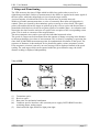
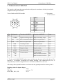
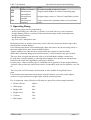
HiTECH Technologies, Inc. User Manual LDL Version 2.5 Laser Distance Measurement Module LDL LDL – User Manual Notes Notes The information in this manual has been thoroughly researched and prepared. Nevertheless, we cannot assume any liability for completion or errors. We would be grateful for any comments or suggestions. No damage claims can be made except for those resulting from intentional harm or negligence. As this product can have several designs, the manual in hand may differ from the product supplied. We reserve the right to make technical changes that serve to improve the product without prior notification. It cannot be assumed that subsequent versions of a product will show the same features as the one described here. Registered trade marks are the property of their manufacturers. LDL – User manual V2.5e For LDL Firmware Version V1.1f HiTECH Technologies, Inc. 301 Oxford Valley Road, Yardley, PA 19067-7711 Technical support: 800. 755. 4507 Tel: 215. 321. 6012 ~ Fax: 215. 321. 6067 www.hitechtech.com ~ [email protected] HITECH 2005 page 2 LDL - User manual Contents Contents 1 General ............................................................................................................................ 4 1.1 Essential features are:...................................................................................... 4 1.2 Safety Instructions ........................................................................................... 5 1.3 Operating Conditions ...................................................................................... 5 2 Components and Accessories.......................................................................................... 6 3 Setup and Functioning..................................................................................................... 7 4 Connection to Cable Port ................................................................................................ 8 5 User Selections ................................................................................................................ 10 5.1 Command list .................................................................................................. 10 5.2 Adjustable Parameters..................................................................................... 11 6 Starting Up ...................................................................................................................... 13 7 Distance Measurement .................................................................................................... 14 8 Speed Measurement ........................................................................................................ 16 9 Operating Range.............................................................................................................. 17 10 Performance Specifications............................................................................................. 18 11 Service, Maintenance, Warranty ..................................................................................... 19 12 Appendix ......................................................................................................................... 20 12.1 Command list .................................................................................................. 20 12.2 Error codes for speed measurement ................................................................ 21 12.3 Pin assignment optional connection box for LDL .......................................... 21 HITECH 2005 page 3 LDL - User Manual General 1 General The compact LDL laser range finder module provides reflectorless, fast and accurate distance measurement to any suitable surface. The used technique of the time-of-flight measurement of laser pulse is particularly suitable for measuring long distances under harsh industrial conditions. Compared with other measuring techniques the extremely short measuring time allows distance measurement to or from moving objects. The LDL is designed for fixed installation on-site. 1.1 Essential features are: • Field operation under extreme temperatures with high accuracy and large working range. • Broad range of operating voltages (10 V= to 30 V=) supplied from an on-board electrical system of motor vehicles, an industry-standard DC voltage net or a DC voltage power pack. • Low, stable power consumption (less than 5 W). • Extension of working range to more than 1500 m for distance and speed measurement applications through additional reflectors mounted on target object. • Simple aiming at targets at close range over notch and bead sighting device. To sight targets located at larger distances, a light point sight is provided. • Collective, flexible, extendable interface cable for supply voltage, bi-directional data interfacing, switching output and analog output. • Commands for measurement functions and output of measured values can be entered at the PC or a laptop. • Switching output and analog output can be programmed separately with different parameters. • Averaging of individual distance readings and plausibility statements with selectable distance measurement times. • Positive or negative excession of distance is signalled via switching output (with selectable distance barrier). • Readout options in metres, feet, inches, and other units of measure made more convenient by randomly selectable scaling. • Class 1 laser according to EN 60825-1:1997-03, absolutely eyesafe, versatile in use. • Automatically detects presence of optical jamming emitters or optical distance sensors along the measurement path. • Measurement can be triggered in synchronised mode from external trigger device. HITECH 2005 page 4 LDL - User Manual General 1.2 Safety Instructions Safety and operating instructions must be read carefully and followed in practical usage! The specified conditions must be observed when operating the LDL. Non-compliance of these instructions or improper usage may physically injure the user, or damage the rangefinder module. In the event of necessary repair, the LDL may be opened by none other than duly instructed service personnel. This is necessary to prevent exposure to dangerous laser radiation or electrical voltages. To operate the LDL, use only DC supply at voltage levels between 10 V and 30 V. Do not operate the module, when its optical components are dimmed or contaminated. Do not touch any optical surfaces of the module with bare hands. Use caution when you remove dust or dirt from these parts. Protect the module from mechanical shocks during operation and transportation. Prevent overheating of the module as a result of lasting direct insolation. This applies also when storing the module in a motor vehicle. 1.3 Operating Conditions The Laser Distance Measurement Module LDL is designed for mobile and stationary distance measurement or speed enforcement performed under field conditions. Range of operating temperatures -20°C to +60°C Range of storage temperatures -40°C to +70°C The rangefinder is splash-proof and built to comply with internal protection standards IP 65. Two threaded holes are provided in the base plate for mounting the module at the operation site. The Laser Distance Measurement Module LDL qualifies for laser class 1 under EN 60825:1997-03. It emits laser radiation which is not harmful to the human eye. No safety precautions or protective measures are required for normal operation. Laser class 1 HITECH 2005 page 5 LDL - User Manual Components and Accessories 2 Components and Accessories Delivery of the LDL includes an interface cable (2 m in length) and a user manual. Shipment is in a stable padded cardboard box which can also be used for safer transportation of the module. The following accessory parts are available on request: • one reserve interface cable of 2 m length, • one light point sight, • one plastic reflector (cat's-eye 84 mm in diameter with central hole for mechanical attachment), • software LDL (Win9x and NT), • connecting box (IP 65). Optionally, an extended interface cable may be provided. It allows for a larger distance between rangefinder position and position of PC and electrical supply if required to match local conditions. Please contact us for a customised solution to your specific requirements! To increase the distance range in distance measurement applications over 100 m and beyond, one or preferentially more plastic reflectors should be affixed on a white sighting screen of 0.5m x 0.5m, which can easily be seen from a large distance. For jobs, where distances beyond 1000 m need to be measured frequently, we are able to provide an easily visible target screen covered with reflective sheeting. The light point sight (part of accessories package) is intended for precise aiming at targets to be measured under daylight or twilight conditions. Performance specifications of light point sight: Temperature range Effective magnification (X) Effective size of sighting point at 10 m distance Diameter of exit pupil Physical dimensions Mechanical attachment Lifetime of one set of batteries Weight HITECH 2005 -10 to +500 C 1 6 mm 11 mm 96 x 45 x 35 dovetail way 50 hours 155 g page 6 LDL - User Manual Setup and Functioning 3 Setup and Functioning The LDL measures the time of flight which invisible laser pulses take to travel to a sighted target and back. Subject to measurement is the diffuse or regular back-scatter signal of the laser pulse, which the rangefinder receives from the target surface. A microcomputer is built into the LDL to fire a diode laser at periodic intervals. Within a selectable measurement time, a series of extremely short infra-red light pulses is emitted. These are focused by the transmitter optics to emerge as a laser beam. The signal pulses reflected back from the target are picked up by the receiver optics and directed onto a photodiode which delivers electrical reception signals of a suitable shape. An evaluation unit determines the time from the emission of a pulse to the reception of the corresponding return pulse. This is used as a measure of the target distance. The microcomputer stores and re-processes the individual measured values. The speed of a target can be determined from the amount of change occurring in the distance to this target during a given time of measurement. This is done by compiling a regression line chart from all individual measurement points for mathematical calculation of the speed. The sequence of distances is then analysed for its plausibility under various acceptance criteria. If an acceptance criterion is not met, an error message will be displayed instead of the speed reading. For each target which can be spotted within the given distance range, the initial distance reading is displayed independently. View of LDL 3 5 1 4 2 (1) (2) (3) (4) (5) Transmitter optics Receiver optics Base plate for mechanical attachment Connector port for interface cable (external power supply, RS232/RS422 interface, switching output, analog output Notch and bead sight, holder for light point sight HITECH 2005 page 7 LDL - User Manual Connection to Cable Port 4 Connection to Cable Port The interface cable must be connected to the cable port in accordance with the pin and jack assignment table provided below. View of back wall of LDL module o Pin contact O Jack contact 1 2 3 4 5 6 7 8 9 10 Pin no. 1 Designation ALARM Function with RS232 black brown red orange yellow green blue purple grey white Function with RS422 Type Digital switching output Digital switching output Jack 2 TxD / RX+ RS232 transmission data RS422 reception data + Jack 3 RxD / RX- RS232 reception data RS422 reception data - Jack Ground potential Jack 4 GND Ground potential 5 TRIG External synchronisation External synchronisation Pin 6 VCC Supply voltage Supply voltage Pin 7 MODE Operating mode Operating mode Pin 8 IOUT Current output Current output Pin 9 TX- RS422 transmission data - Jack 10 TX+ RS422 transmission data + Pin *) To the switch RS422/RS232 please open and decrease the rear wall of the device. The interface is to configure accordingly the internal labelling. The transmission pin (TX) is independently from the configuration active for RS422 and RS232 in each case. All voltage values quoted hereafter are referenced to the ground potential at contact point 4. Limiting values for input voltages: TxD ±15V TX+,TX 0.3 V to +7 V RxD, TRIG, RX+, RX±25 V HITECH 2005 page 8 LDL - User Manual Connection to Cable Port Output voltages: TxD ≥ ±5 V with 3 kOhm load at either point ≥ 2 V differential at 100 ohm load TX+,TXAll outputs are protected against steady-state shorts. Interface parameters Baud rate Character length Parity Stopbit length Preparation measurements 1200 to115200 Bit/s 9600 Bit/s set as standard 8 bit none one with baud rate 9600 Bit/s after 15 ms completed ALARM output Output voltage Output current ≥ supply voltage - 2 V ≤ 0.5 A Analogue current output Current range Accuracy Temperature drift 4 mA ... 20 mA (max. 500 ohm load resistance against GND) ± 0.15% < 50 ppm/°C Trigger (external triggering) RS 232-levels Trigger threshold Trigger age until laser-impulse Precision trigger time Length trigger pulse Maximum frequency Delay time in ms Active trigger age Preparation measurements ± 25V + 1,5V 5 ms + put in delay time 1 ms ± 1 % of put in delay time ≥ 1 ms 100 Hz (minimal average time 10 ms) 0 to 9999 adjustable adjustable 15 ms after trigger event completed HITECH 2005 page 9 LDL - User Manual User Selections 5 User Selections The LDL offers a menu with comprehensive setting options. The module can, thus, be matched to the local site conditions or the particular measurement task before a job sequence is triggered. Once voltage is supplied and the internal self-testing routine has been completed successfully, the measured values are displayed cyclically in automatic mode. Internal non-correct functions of the LDL are reported via special messages with a correlated error code. Cyclic output of measured values is provided with 100 Hz averaging factor. No data transmission log is created in this case. Each measurement function with cyclic data output needs to be terminated by ESC (1Bh) The rangefinder module is then ready to receive control commands as described in the list below. 5.1 Command list Command ID<CR> Function Identification TP<CR> Internal temperature Baud rate BRnn<Cr> DJ<CR> DT<CR> or after turning power ON VM<CR> VT<CR> ACnn<CR> AHnn<CR> RBnn<CR> REnn<CR> SAnn<CR> SFnn<CR> HITECH 2005 Cyclic output: strength of received signals Cyclic output: single distance values Single speed and distance Cyclic output of speed and distance Alarm Center Response One line consisting of device type, copyright, software version number and serial number TTT<CR><LF> complete numerical input for the baud rate, sees chapter parameters [][][][]JJJJ 1 value per measurement, repetition rate 100Hz Output rate: 100Hz/ averaging factor []DDDD.DD if measurement correct []9999.99 no target or target too distant SVV.V[]DDDD.D[]PPPP<CR><LF> If measurement correct []ECC[]DDDD.D[]PPPP<CR><LF> If measurement with initial distance reading failed []ECC[]PPPP<CR><LF> If measurement impaired or system error Same as single speed Approx. Number of measurements p. sec. No response if value set with parameter nn; if no parameter, set value is displayed Alarm Hysteresis Same as Alarm Center Range Beginning Same as Alarm Center Range End Same as Alarm Center Set Average Same as Alarm Center (integer numbers 1.....1000) Scale Factor Same as Alarm Center page 10 LDL - User Manual User Selections Command TDn1[]n2<CR> Function Trigger AS[]cc<CR> Auto start DF<CR> Cyclic output: single distance values with external trigger Response n1 Verzögerungszeit in ms n2 Triggerflanke 0 oder 1 (0 =1→0 ; 1=0→1) Definition eines Befehls beim Einschalten, sinnvolle Befehle sind DT, DJ, DF, TP und ID Output rate = Trigger frequency / Average factor []DDDD.DD if measurement correct []9999.99 no target or target too distant [] CR LF DDDD.DD JJJJ cc nn PPPP = = = = = = = = S TTT V.VV = = = Space ( 20h ) Carriage Return ( 0Dh ) Line Feed ( 0Ah ) Distance value in metres, with cm resolution Adjustment value (no unit of measure, range about 100 ... 6000) DT, DJ, DF, TP and ID (Auto start command) Set parameters in fixed or float point notation CRC data check sum according to CCITT over all preceding characters since output of <CR><LF> Mathematical sign: space for positive, - for negative Temperature value in °C, with mathematical sign Speed value in m/s, negative sign designates targets moving away E CC = = Error sign Error code 10 11 12 14 no optical reflex signal less than 50 optical reflex signals too much spread in measured values measurement was impaired 5.2 Adjustable Parameters The following parameters can be selected. They are preserved after turning the LDL off and are immediately available for use in distance tracking mode when power is turned on again. A parameter of this type can only be changed by entering a new value for it. Averaging factor: To select averaging of 1 to 1000 successive distance shots each time before the distance value is output; is factory-set to SA1. A distance measurement becomes caused all 10 ms in case of distance tracking DT, in case of tracking with trigger DF it becomes caused if a trigger event occur. Scaling: For multiplication of distance value with a selectable factor to achieve a change in resolution or output of results in a different unit of measure Alarm Center: Allows selection of distance switching threshold for the switching output HITECH 2005 page 11 LDL - User Manual Alarm Hysteresis: User Selections Allows selection of switching hysteresis for switching output With positive hysteresis, output ON switches in the event of positive excession of switching threshold +hysteresis/2 and output OFF in the event of negative excession of switching threshold hysteresis/2. With negative hysteresis, output OFF switches in the event of positive excession of switching threshold +hysteresis/2 and output ON in the event of negative excession of switching threshold - hysteresis/2. Range Beginning: Lower distance limit of selectable distance interval Range End: Upper distance limit of selectable distance interval Trigger: Measurement frequency is depending on the trigger frequency in distance tracking mode with external trigger DF ( max. 100 Hz + 1% ) In case of self triggering in distance measuring mode DT the measurement frequency is constant 100 Hz. Baud rate: The baud rate can set with following parameters (Bit/s: 1200, 2400, 4800, 9600, 19200, 38400, 57600, 115200 Hint: With the reduction of the baud rate under 9600 Bit/s, the output rate must be reduced likewise. Baud rate Output rate 4800 Bit/s 2400 Bit/s 1200 Bit/s 50 Hz 25 Hz 12.5 Hz Average factor ≥2 ≥4 ≥8 The device delivery always with the baud rate 9600 Bit/s. Hint: Auto start: HITECH 2005 The set baud rate becomes active after a reboot! Please write down the set baud rate. The commands DT, DJ, DF, TPS and ID can be set. If no Auto start function wished the command can erased by input of three blanks. page 12 LDL - User Manual Starting Up 6 Starting Up To get ready for measuring in a selected field position, train the LDL on the object to be measured (keep adjusted position stable while measurement is going on). In stationary mode, the positions of rangefinder and moving target are known. In this case, the direction of measurement must be identical with that of target motion. With mobile or hand-held measurement, the time for which the laser beam dwells on the target must at least be as long as the time which the laser distance module takes to perform measurement. Speed measurement requires a measuring time of 0.5 s. The time for distance measurement can be selected. Coarse alignment of the measuring beam for a clearly visible target at up to 150 m distance can easily be achieved with the notch-and-bead sighting device. Operating voltage is supplied at the corresponding connection points of the interface cable. A special protection logic is provided to prevent destruction of the electronic components as a result of unwanted pole reversal. The rangefinder comes factory-set to an averaging factor of SA1. Distance measurement readings are displayed at 100 Hz intervals immediately after operating voltage is supplied. The measured values can be displayed with the help of a suitable PC terminal program (8N1 and standard delivery 9600 Bit/s). Or use an optional program for Windows 98 and Windows NT. For the Windows-program, a separate handbook is available. Use the command DJ for precisely aiming at a selected target. The output values indicate the strength of the return signals. Change the rangefinder's alignment slightly, until a maximum in value is obtained. Alignment for targets at a range above 150 m should preferentially be done using the optional light point sight. To perform mutual alignment of light point sight and measuring beam, the LDM 300 C should be trained on a small strongly reflecting solitary target, and the alignment should be optimised by determining the point of maximum signal strength. To change to distance output mode, press ESC and trigger command DT, or turn power off and on again. The Auto start commands can be set to start function DT, DJ, DF, TPS or ID after reboot. If no Auto start function wished the command can erased by input of three blanks (command AS). HITECH 2005 page 13 LDL - User Manual Distance Measurement 7 Distance Measurement By selecting an averaging factor, a desired output rate (100/ averaging factor), measuring time (1/output rate) and statistical spread can be defined for distance measurement. Example: Output rate Time to measure Statistical spread Averaging factor over white screen of 0.5 m x 0.5 m located at right angles with measurement direction at a distance of 100m 1 Hz 10 Hz 100 Hz 1s 100 ms 10 ms ± 1 cm ± 2 cm ± 7 cm SA100 SA10 SA1 Entering a scale factor SF allows virtually random selection of a desired scale for distance readings. The scale factor acts independently of the currently set averaging factor. You can, thus, match the resolution of measured values and the unit of measure to the particular measurement task. Examples: Resolution Reading Unit of measure Scale factor 1 cm 1 mm 0.01 yard 0.01 feet 1 inch _234.56 2345.61 256.52 769.56 92.35 m dm yard feet 100inch SF1 SF10 SF1.0936 SF3.28084 SF0.3937 The switch output signals positive or negative excession of a pre-defined distance switching threshold with hysteresis band (Alarm Center). The switching hysteresis for distance mode is defined through selection of a switching threshold (Alarm Hysteresis). Example: Monitoring a closed door relevant for safety consideration located at a distance of 100 m; door opens toward measuring site. Command SA100 Command SF1 Command AS[]DT Command AC99.70 Command AH0.10 1 Hz distance output rate (switching mode option) 1cm resolution, unit of measure: m Distance tracking Distance switching threshold set at 99.70 m Distance hysteresis set at 10 cm The switching output will be in ON status when a distance of 100 m has been measured. As the door opens, the output switches to „OFF“ at the moment the measured distance equals 99.60 m. It remains in OFF status with any distance less than 99.60 m. When the door is subsequently closed again, the output switches back to „ON“ as soon as the measured distance exceeds a value of 99.80 m. The hysteresis value should be selected to be larger than the actual spread in measured values. HITECH 2005 page 14 LDL - User Manual Distance Measurement For standardised analog two-wire transfer of distance data over greater lengths, an analog output port is provided. The current signal impressed on this transfer line is proportional to the measured distance within a distance interval that can be selected via „Range Beginning“ and „Range End“. The value for output current (in mA) is determined through the following calculation formula: Dist . val.− Rnge. Begin IOUT (mA) = 4 + 16 * Rnge. End − Rnge. Begin If, in accordance with this formula, positive excession of „Range End“ causes an output current above 20 mA or negative excession of „Range Beginning“ an output current below 4 mA, then limit value 20 mA or 4 mA will be reported. HITECH 2005 page 15 LDL - User Manual Speed Measurement/Operating Range 8 Speed Measurement Short measuring times (0.5 s) allow motor vehicles to be monitored even at high travel speeds. Make sure the rangefinder is continuously aimed at the same spot on the vehicle as long as measurement lasts. To facilitate this process, the light point sight can be mounted onto a stand for tracking the target. This helps obtain unblurred readings and reduces operator fatigue during observation and measurement. The aiming path must be free from bushes, trees, masts, persons, etc. to assure direct visual contact with target and unobstructed passage of the measuring beam. There must be no depressions or elevations in the road section which is passed by the vehicles during speed measurement. These would require up or down tilting of the rangefinder while the respective vehicle is tracked for speed measurement. Continuos tilt motion, especially up or down variations over the vehicle's body shape or the surface of the road should be avoided during any measurement process. The directions of measurement and vehicle motion should have a preferentially small mutual angle. Otherwise, the amount of change in vehicle distance registered in the direction of the rangefinder is smaller than the actual distance the vehicle has covered on the road. Since the changes in distance are referenced to fixed time intervals to serve as the basis for speed calculation, the recorded speed would be lower than the actual motion speed of the vehicle if the mutual angle gets too large. This is also known as the "Cosine effect". The selected target distance should be at least ten times larger than the possible lateral offset of the measurement site from the direction of vehicle motion. In this case, the recorded speed is only just 0.5% lower than the actual vehicle motion speed. Examples: With a lateral offset of 10 m, speed measurement should be over 100 m or more. Accordingly, when there is a lateral offset of 15 m, the target distance should be equal or larger than 150 m, etc. A single shot in speed mode can be triggered via VM command, a sequence of single shots via command VT. One single shot consists of 50 distance readings obtained at a repetition rate of 100 Hz. The measuring time of 0.5 s is followed by an evaluation time portion of 0.125 s. A sequence of single shots consists of single shots which are triggered at intervals of 0.625 s. Each speed reading is displayed in units of m/s. The minimum required limiting distance for achieving reasonable speed results is 0.5 m. The upper limit for target distances in speed monitoring depends on the target's reflectivity, on the potential stray light influences and atmospheric conditions. For licence plates, this limit is at 600 m, for example. Each single shot is recorded with an accuracy of 0.3 m/s. The measured speed values are displayed together with the motion direction of the targeted vehicle. This is done via a „-“ sign for approaching vehicles (preceding the speed value). In the event of away motion, the speed values are represented without mathematical sign. No output or failure to produce distance readings within a defined time, too much spread in the measured values for evaluation by regression line, or measurement impaired by an optical jamming source or a distance sensor will produce an Ecc error message. HITECH 2005 page 16 LDL - User Manual Error code E10 E11 E12 E14 Speed Measurement/Operating Range Type of error Failure to measure Measurement uncompleted Measurement unstable Measurement impaired Cause No target recorded or target too remote Target partially hidden or at limit of operating range Irregular target contour or "blurred" rangefinder position Target contains laser jamming emitter or laser distance sensor 9 Operating Range The operating range may be constricted by: - surfaces providing poor reflection (e.g. black) or covered with very coarse structures, - strongly shining surfaces or surfaces with an inclination angle to the measuring beam, - strongly isolated surfaces, - strong back lighting, - fog, rain, snow, atmospheric dust. Reflecting surfaces or window panes may re-direct the laser beam onto another target, thus, falsifying the recorded distance. If the measurement beam is directed through a glass sheet, there may be mirroring effects or the beam might fall on other objects behind the glass. Targets smaller in size than the laser measurement spot cannot be sighted reliably. When there is blurring during the measurement time, various distances may get recorded. These are then averaged and the mean value over all individual readings is turned out. If, at the time of target sighting, a reflecting object happens to be near the measuring beam, but before the target, the rangefinder result may be falsified. In many cases, a sheet of white paper or cardboard can be applied for better target definition. A plastic reflector from the optional accessories set should be used only for distances over 100 m. The zero-point for LDL distance measurement is in the middle of rangefinder's base plate. Laser measurement determines the distance from this distance zero-point to the sighted surface of a target positioned at right angles with the measuring beam. For a comparison, some reflection coefficients are quoted for various sample materials: • Plastic reflector 2000% • White paper 90% • Bright walls 80% • Bright wood 40% • Concrete 30% • Black paper 10% HITECH 2005 page 17 LDL - User Manual Performance Specifications 10 Performance Specifications Specification: Measurement range*1: Laser divergence*2: Laser classification: Operating temperature: Storage temperature: Shock (DIN 58390-30-02-0): Supply voltage*7: Power consumption*8: Data interfacing*7: Switching output*7,9: Analog output*7,9: Trigger input: Dimensions (L x W x H): Weight: Internal protection standards: Mech. mounting: Included in delivery: Optional accessories: Distance measurement: Measuring accuracy*3,4: 0.5 m to 400 m on white surface up to 200 m on earth or concrete beyond 1500 m on plastic reflector 3 mrad Class 1 laser as per EN 60825-1:1997-03 -20°C to +60 °C -40°C to +70 °C 10 shocks at 98 m/s² and 6 ms 10 V to 30 V DC <5W RS 232 / RS 422 (switch able), Baud rate 9600 to 115200, format 8n1, selection of measurement functions, scaling, measuring time via commands, output of measured values, internal temperature, error codes Programmable switching threshold and hysteresis, „high-side switch“, permissible load up to 0.5 A, Uswitch > Usupply - 2V Current output 4 mA to 20 mA, programmable distance range limits, load resistance ≤ 500 Ω Delay time and active age programmable 139.9 mm x 70.8 mm x 108.3 mm 850 g IP 65 2 threaded holes M6 x 6 deep LDM 300 C, interface cable, user manual Reserve interface cable, light point sight, connection box, plastic reflector, software for Windows 98 and NT Resolution of measured values*5: Statistical spread*6: with measuring time of: ± 5 cm from -10 °C to +40 °C ± 10 cm from -20 °C to +60 °C 1 mm, randomly scaleable ± 7 cm ± 2 cm ± 1 cm 10 ms 100 ms 1s Speed measurement: Speed range: Measuring accuracy*3: Measuring time: 0 ms-1 to 70 ms-1 0.3 ms-1 0.5 s *1 *2 *3 *4 *5 *6 *7 *8 *9 Depends on target reflectivity, stray light influences and atmospheric conditions At a distance of 100 m, the beam diameter is 0.3 m Reflection coefficient ρ > 20% Standard deviation Units of measure: m, dm, yard, feet, 100 inch; accuracy selectable to two digits after decimal point When sighting a planar white screen at 100 m distance positioned at right angles with the direction of measurement One jack port for supply voltage, RS 232/RS 422, switching output, analog output, Not considering switched electrical load Only for distance measurement HITECH 2005 page 18 LDL - User Manual Service, Maintenance, Warranty 11 Service, Maintenance, Warranty Warranty will be one year. During this warranty period, the LDL can be checked for proper function if requested by the customer. This check will be carried out at no cost to the customer. To check all product functions and allow unobstructed handling of your business commitments, we would suggest that you have the laser distance measurement module LDL inspected at our facility after 4500 operating hours or at yearly intervals. Should a repair become necessary, please pack the rangefinder carefully and send it to our address. EG Conformity Declaration According to the terms of EMC Directive 89/336/EWG, Appendix 1 the: Laser Distance Measurement Module LDL complies with the harmonised standards in EN55022 (class B) and EN 50082, Part 2. Jena, on the 24th of March 1998 HITECH 2005 page 19 LDL - User Manual Appendix 12 Appendix 12.1 Command list Command ID<CR> Function Identification TP<CR> Internal temperature Baud rate BRnn<Cr> DJ<CR> DT<CR> or after turning power ON VM<CR> VT<CR> ACnn<CR> AHnn<CR> RBnn<CR> REnn<CR> SAnn<CR> SFnn<CR> TDn1[]n2<CR> AS[]cc<CR> DF<CR> Cyclic output: strength of received signals Cyclic output: single distance values Single speed and distance Cyclic output of speed and distance Alarm Center Response One line consisting of device type, copyright, software version number and serial number TTT<CR><LF> complete numerical input for the baud rate, sees chapter parameters [][][][]JJJJ 1 value per measurement, repetition rate 100Hz Output rate: 100Hz/ averaging factor []DDDD.DD if measurement correct []9999.99 no target or target too distant SVV.V[]DDDD.D[]PPPP<CR><LF> If measurement correct []ECC[]DDDD.D[]PPPP<CR><LF> If measurement with initial distance reading failed []ECC[]PPPP<CR><LF> If measurement impaired or system error Same as single speed Approx. Number of measurements p. sec. No response if value set with parameter nn; if no parameter, set value is displayed Alarm Hysteresis Same as Alarm Center Range Beginning Same as Alarm Center Range End Same as Alarm Center Set Average Same as Alarm Center (integer numbers 1.....1000) Scale Factor Same as Alarm Center n1 Verzögerungszeit in ms Trigger n2 Triggerflanke 0 oder 1 (0 =1→0 ; 1=0→1) Auto start Definition eines Befehls beim Einschalten, sinnvolle Befehle sind DT, DJ, DF, TP und ID Cyclic output: Output rate = Trigger frequency / Average factor single distance []DDDD.DD if measurement correct values with []9999.99 no target or target too distant external Trigger Meaning of codes see text. HITECH 2005 page 20 LDL - User Manual Appendix 12.2 Error codes for speed measurement Error code E10 E11 Type of error Failure to measure Measurement uncompleted Measurement unstable Measurement impaired E12 E14 Cause No target recorded or target too remote Target partially hidden or at limit of operating range Irregular target contour or "blurred" rangefinder position Target contains laser jamming emitter or laser distance sensor 12.3 Pin assignment optional connection box for LDM 300 C 12.3.1 Connection 1, serial interface Pin-number 1 2 3 4 5 Colour internal brown white blue black grey Assignment as RS232 RxD TxD GND don’t use don’t use Assignment as RS422 * RX + RX don’t use TX TX+ *) To the switch RS422/RS232 please open and decrease the rear wall of the device. The interface is to configure accordingly the internal labelling. The transmission pin (TX) is independently from the configuration active for RS422 and RS232 in each case. 12.3.2 Connection 2, Signal Pin-number 1 2 3 4 5 Colour internal brown white blue black grey Assignment IOUT (4 to 20 mA) ALARM (output) GND (zero potential) TRIG (Synchronisation) MODE Remarks Rmax = 500 Ohm U = 0 or (Ub-2V); Imax=0,5A for all signals 0 to 24 V don’t use 12.3.3 Connection 3, Power supply 24V/DC Pin-number 3 4 PE Colour internal black red gn/ye Assignment negative (GND, 0 Volt) positive (Ub, 24 Volt) Earth Remarks GND = zero potential Ub = 10 to 30 V connect with installation-earth shortly 12.3.4 Box connections 3 2 1 Holes for mounting 4 x M6, 106 x 82 mm HITECH 2005 page 21