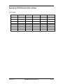
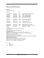
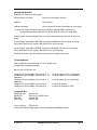
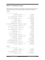
1
REIXS Beamline
Reference Manual
(Work in Progress)
Feizhou He
Updated: April 28, 2015
TABLE OF CONTENTS
1.0
Introduction ................................................................................................ 1
2.0
Advanced Controls ..................................................................................... 1
2.1
3.0
3.2
Beamline Pump Down .................................................................. 1
2.1.2
RSXS Endstation Pump Down ...................................................... 1
2.1.3
Turn on the Electronics ................................................................. 1
Calibrating the Beamline Components ..................................................... 2
3.1.1
EPU Calibration ............................................................................ 2
3.1.2
Calibrating Apertures and Slits ..................................................... 3
3.1.3
Calibrating Mirror positions ........................................................... 4
3.1.4
Calibrating Chopper ...................................................................... 4
3.1.5
Monochromator Calibration........................................................... 5
Calibrating the Photon Energy.................................................................. 8
3.2.1
Calibration References ................................................................. 8
3.2.2
Tuning the Monochromator Energy Scale ..................................... 8
RSXS Endstation Setup ............................................................................. 9
4.1
4.2
4.3
4.4
5.0
2.1.1
Beamline Setup .......................................................................................... 2
3.1
4.0
Starting the Beamline from Scratch .......................................................... 1
RSXS Endstation Pump Down ................................................................. 9
4.1.1
Scattering chamber Pump Down .................................................. 9
4.1.2
Rotary Feedthrough Pump Down................................................ 10
4.1.3
Loadlock Pump Down ................................................................. 10
4.1.4
Transfer chamber Pump Down ................................................... 10
Setup RSXS Endstation Electronics ....................................................... 10
4.2.1
Detectors .................................................................................... 10
4.2.2
Scaler Setup ............................................................................... 10
4.2.3
Temperature Control Setup ........................................................ 11
Setup Motors and SPEC ........................................................................ 11
4.3.1
AML UHV Motors ........................................................................ 11
4.3.2
Attocube ANC350 Controller....................................................... 12
4.3.3
Macro Motors.............................................................................. 15
Setup SPEC Control .............................................................................. 15
XES Endstation Setup .............................................................................. 15
April 28, 2015
REIXS Beamline Reference Manual
Page i
5.1
XES Endstation Pump Down .................................................................. 15
5.2
Setup XES Endstation Electronics ......................................................... 16
Appendix A: REIXS Beamline Motor Settings ..................................................... 17
Appendix B: REIXS Information .......................................................................... 18
Appendix C: Attocube Motor Settings ................................................................. 20
April 28, 2015
REIXS Beamline Reference Manual
Page ii
1.0 Introduction
The Resonant Elastic and Inelastic Soft X-ray Scattering (REIXS) Beamline is a soft X-ray
beamline dedicated to soft X-ray scattering and soft X-ray spectroscopy experiments. The
beamline is located at 10ID-2 port of Canadian Light Source.
This document describes the setups and calibration of REIXS Beamline.
2.0 Advanced Controls
2.1
Starting the Beamline from Scratch
All valves closed
2.1.1 Beamline Pump Down
If one vacuum section has been vented, use turbo cart to pump down to below 10-6 Torr.
Bakeout the section.
Pumps, pump down individual vacuum sections, bakeout
Before a power outage, close all gate valves to isolate each vacuum section. If the power
outage is less than 2-3 days, usually the vacuum can be recovered by turning on the ion
pumps in each section. Otherwise, use turbo cart to pump down each section to below
10-6 Torr before turning on the ion pump.
2.1.2 RSXS Endstation Pump Down
Turbo pump for scattering chamber and load lock.
Pump down the Cryo pump by either chamber turbo pump or through the roughing port
on the cryo pump. Then start cryo pump.
Pump down the Thermionics 2L/s ion pump for the rotary feedthrough differential
pumping. Close the valve to turbo roughing line. Connect a turbo cart, open both valves
on the differential pumping line. Pump the differential pumping line to <10-6 Torr, then
start the ion pump. Current < 5mA?? Close the valve besides the 2L/s ion pump. Close
the valve to turbo cart. Open the valve to 700L/s turbo roughing line.
2.1.3 Turn on the Electronics
IOC1610-201
OPI1610-201
OPI1610-202
IOC1610-403
Start VME crates
Start NIM crate
Start control software for the beamline
April 28, 2015
REIXS Beamline Reference Manual
Page 1
3.0 Beamline Setup
Power ready
Air ready
Cooling ready
Vacuum ready.
3.1
Calibrating the Beamline Components
3.1.1 EPU Calibration
For qualified beamline staff only.
The REIXS EPU Control can be accessed by
typing: runREIXS_Epu & from a command
line window (xterm), or click the [R-EPU]
button in the REIXS Advanced Control
Interface.
Clicking the [Calibrate EPU] button will bring
up the EPU Calibration panel. Clicking [Run]
button in the “Calibrate EPU” line will
automatically calibrate all five motors on the
REIXS EPU. Clicking other [Run] buttons will
calibrate individual motors. When all the
motors are calibrated, the calibration status
shows Calibrated with green beackground.
Other details of the REIXS EPU could also be
accessed from this interface. DO NOT make
adjustments without comprehensive
knowledge of EPU control.
April 28, 2015
REIXS Beamline Reference Manual
Page 2
3.1.2 Calibrating Apertures and Slits
REIXS Beamline has several apertures / slits.
3.1.2.1 Variable Aperture
Variable Aperture
3.1.2.2 4-Jaw #1 and 4-Jaw #2
4-Jaw #1 and 4-Jaw #2
3.1.2.3 Exit Slit
Exit Slit has four motors.
Vertical gap: beam based calibration
Inboard and outboard blade motors are the same as 4-Jaw motors.
Roll motor
April 28, 2015
REIXS Beamline Reference Manual
Page 3
3.1.3 Calibrating Mirror positions
For qualified beamline staff only.
It is not necessary to move the mirrors for encoder calibration. Use procedure below for
every motor / encoder pair for each mirror:
1. Open motor control interface for one motor.
2. Verify the settings for motor velocity, base velocity and acceleration. Make
corrections if needed.
3. On Power/Backlash tab, turn off the Motor Power.
4. Go to Calibration tab, verify the values of Step Slope, Encoder Slope and Calib
Position. Make corrections if needed.
5. Click the Home CW button. The motor feedback value should be changing.
6. Go to the corresponding motor, push the encoder tip back. Once the reference mark
is detected, the motor feedback value will stop. The encoder is calibrated now.
7. Go back to Power/Backlash tab and turn on the motor power (or Auto Hardware for
some motors).
Other details of the motor could also be accessed from this interface. DO NOT make
adjustments without comprehensive knowledge of motor control.
3.1.4 Calibrating Chopper
Chopper must rotate in the positive direction for correct operation. If the chopper has
moved in negative direction, it must rotate in positive direction for one revolution, so that
the encoder can pass the home position reference mark and establish the correct angle
readout.
LED indicators on the Chopper Controller in the NIM
Crate show the status of the chopper system.
Once chopper is stopped, use “Move Relative” to
adjust chpper position.
[SYNCD] – Chopper calibrated
[DS1] – Data stream 1 (REIXS EPU Beam)
[DS2] – Data stream 1 (SM EPU Beam)
April 28, 2015
REIXS Beamline Reference Manual
Page 4
3.1.5 Monochromator Calibration
For qualified beamline staff only. DO NOT make adjustments without
comprehensive knowledge of monochromator control.
Verify motor parameters: velocity, base velocity, accelaration
Translation motors calibration
In the “REIXS Energy” panel, click
[ENABLE] button to activate the
energy control. Use the input box
to set the energy for
monochromator and EPU. Click
[Stop] button to stop all motors of
monochromator and of EPU
immediately. “Status” shows if the
monochromator and EPU have
reached correct setpoints.
The [Disable/Enable] buttons are
used to activate/deactivate
individual components.
1.1.1.1 Selecting Gratings and M2 Coatings
The REIXS monochromator has
three gratings. There are four
coatings the M2 mirror.
In the “Monochromator” panel,
user can select which grating and
coating are used. The setpoint and
feedback values are also
displayed.
April 28, 2015
REIXS Beamline Reference Manual
Page 5
3.1.5.1 Configure EPU Access
This panel is used to switch EPU access.
Normal mode: [REIXS Only]
2-in-1 mode: [REIXS & SM]
1.1.1.2 Selecting EPU Harmonics
Depending on the desired photon
energy range, appropriate EPU
harmonics shall be selected for
optimum flux.
For circular polarization, only the
first harmonics can be used.
For linear polarization, use the first
harmonics for energy between 80
eV and 1000 eV. Use the third harmonics for energy between 800 eV to 2000 eV. Use the
fifth harmonics for energy above 1500 eV.
After executing the command to change EPU harmonics, the EPU does not respond
immediately. The EPU harmonics will change the next time energy or polarization is
changed.
When the EPU control is established, the
“Access” field shows “ENABLED”
3.1.5.2 Setup EPU Lookup Tables
The [Configure EPU] button will bring up
the panel for loading EPU lookup tables for
gap and girder phase control.
Polynomial
April 28, 2015
REIXS Beamline Reference Manual
Page 6
1.1.1.3 Monochromator Parameters
Clicking [Configure Mono] button will bring up the following panel. In this panel, various
monochromator parameters can be configured. This is to be used by beamline staff only.
Grating parameters
Line Density
Position
b2
Grating offset
Mirror Offset
Mirror position
For both grating and
mirror
Max retry: 0
Deadband: 0.00005
Percent approach: 100%
April 28, 2015
REIXS Beamline Reference Manual
Page 7
3.1.5.3 IK320 Encoder interface
For qualified beamline staff only. DO NOT make adjustments without
comprehensive knowledge of monochromator control.
For both M2 mirror and Gratings
Sample rate 0.04sec 50Hz
Initialization [Run Init]
“Init completed: SUCCESS”
Calibration
[Card 1 + 2] and [RUN]
“Calibrated” with green
background
3.2
Calibrating the Photon Energy
3.2.1 Calibration References
3.2.1.1 Using Gas cell
X-ray Photoionization of gas phase
Nitrogen, Neon, Argon, Carbon monoxide or Carbon Dioxide, Oxygen
3.2.1.2 Solid references
Through X-ray Absorption Spectroscopy (XAS) of well-defined absorption edges
Metal, Ni, Stainless Steel
Oxides: La edge, Ni edge,
Si, graphite
3.2.2 Tuning the Monochromator Energy Scale
The REIXS Mono Calibration panel is used to fine tune the monochromator calibration.
The calibration needs to be carried out for each grating.
April 28, 2015
REIXS Beamline Reference Manual
Page 8
Using a calibration reference with known energy,
optimize the flux by adjusting monochromator M2
mirror and grating pitch. Input the known energy
into the red “Energy” box. Then input the two red
“Offset” values into the corresponding “Grt
Offset” and “M2 Offset” boxes. Click the Grating
button above this column. The “USE” column will
show the current used values. The
monochromator is now calibrated to this
reference energy.
1.1.2 Tuning the EPU Calibration
To be done only after monochromator calibration.
Needs to be done for each type of polarization.
Scan EPU gap at each energy point.
Using polynomial equations to calculate EPU gap.
4.0 RSXS Endstation Setup
Need to reach UHV. Setup motors. Setup detectors.
4.1
RSXS Endstation Pump Down
RSXS Endstation has several chambers.
4.1.1 Scattering chamber Pump Down
The main scattering chamber has a Pfeiffer Turbo pump and a CTI cryo pump.
Two gate valves
1. Open the gate valve to the turbo pump. If cryo pump is at room temperature, open
the gate valve to the cryo pump.
2. Turn on roughing pump.
3. Turn on turbo pump.
4. Turn on ion gauge when the Convection gauge shows 0
5. Turn on cryo pump. The Lakeshore 211 Temperature Monitor shows the cryo pump
temperature, ~15K during the normal operation.
RGA on the Scattering Chamber.
April 28, 2015
REIXS Beamline Reference Manual
Page 9
4.1.2 Rotary Feedthrough Pump Down
The 2L ion pump on rotary feedthrough needs to be pumped down before start.
1. Close the valve to the main chamber roughing line.
2. Connect a turbo cart to the pumping port for the rotary feedthrough.
3. Open the valve between the first and second stage of the rotary feedthrough.
4. Turn on the turbo cart.
5. When the turbo cart reaches base pressure, turn on the small ion pump. Green light
6. Close the valve between the first and second stage of the rotary feedthrough.
7. Open the valve to the main chamber roughing line.
8. Close the valve to the pumping port for the rotary feedthrough.
9. Stop the turbo cart.
4.1.3 Loadlock Pump Down
Pfeiffer Turbo pump:
1. Close loadlock door. Close gate valve.
2. Turn on roughing pump
3. Turn on turbo pump. The venting valve will close automatically.
4. Turn on ion gauge when the Convection gauge shows 0
4.1.4 Transfer chamber Pump Down
4.2
Setup RSXS Endstation Electronics
Turn on power to the NIM Crate and VME Crate in the endstation electronics rack.
4.2.1 Detectors
Photodiode: connected to Electrometer through a Triax cable
TEY: SR-570 Current Amplifier
Channeltron: Ortec
Micro-Channelplate (MCP):
4.2.2 Scaler Setup
SIS3820
Scaler Setup
Input Mode: Mode 4
Output Mode: 2
April 28, 2015
REIXS Beamline Reference Manual
Page 10
Mode: Continuous
Source: Clock
4.2.3 Temperature Control Setup
Lakeshore 325 Temperature control
Temperature Sensor: Si Diode DT-670
Heater: 25 Ω, 25W max
PID setting
4.3
Setup Motors and SPEC
There are nine AML UHV motors and two Attocube piezo motors in the Scattering
chamber.
4.3.1 AML UHV Motors
The AML UHV motors are controlled by SPEC as epics motors. The APS motor record
connects to CLS motor record through a wrapper software.
Motor parameters:
TTH, tth, …
Motor temperature: Omron Temperature monitor, keep temperature below 65°C.
April 28, 2015
REIXS Beamline Reference Manual
Page 11
4.3.2 Attocube ANC350 Controller
The two piezo motors inside the polarization analyzer are controlled by the Attocube
ANC350 Controller.
Initial setup
To setup the Attocube controller and motors, quit FOURC first. After power
on the ANC350, from Windows computer, open the Attocube folder on the
desktop.
The software “dgdiscvr.exe” is used to
setup the IP address for the ANC350
controller.
The ANC350 is connected to the REIXS
VLAN (642)
Host name: MC2E1610-401
Domain: clsi.ca
Static IP address: 10.52.11.100
Subnet mask: 255.255.252.0
Default Gateway (routers):
10.52.11.254
Confirm the network
connection is established.
Software “daisy.exe” is used to setup the
motor parameters.
Open the “daisy” software. It will try to
connect to the ANC350 server. Once
connected, the left indicator at the bottom
will be green. If it failed to connect to
ANC350, click the “start” icon (like a
thunderbolt) to try again.
April 28, 2015
REIXS Beamline Reference Manual
Page 12
Once connected to the ANC350, click “Open
File” icon, and select “ANC350_3.ngp”
profile. There will be four tabs opened in
“Daisy” interface.
The first tab is Global Settings. Keep the
default values.
The second tab is for ANR101/RES Motor.
This motor is used to position the
multilayers for either horizontal
polarization or vertical polarization.
The default motor profile can be loaded
using “Load Actor profile” button and then
choose “ANR101res_95_171.aps” file.
April 28, 2015
REIXS Beamline Reference Manual
Page 13
Uncheck the “Target Ground” checkbox. This parameter could not be changed within
FOURC.
The third tab is for ANRv51/RES Motor.
This motor is used to change the
multilayers and also to scan the analyzer
theta angle.
The default motor profile can be loaded
using “Load Actor profile” button and
then choose “ANRv51_C4_029.aps” file.
Also uncheck the “Target Ground”
checkbox.
The fourth tab (ANC350 Axis 3) is not
used.
Now close all tabs by clicking the “close”
icon (red cross). And then disconnect the ANC350 server by clicking the “shutdown” icon
(blue handgun).
The ANC350 front panel is shown above. The first slot is the master module, and shows
the driving voltage of the module in focus. The second and third modules are for the
Analyzer and ATH motors, respectively. The current angular position or holding voltage is
shown. Refer to Attocube User Manual for more information.
Setup in FOURC
Start SPEC using “runFOURC”. If you see startup message as following, quit SPEC and try
again (or use “reconfig”):
Getting configuration parameters from "SPECD/fourc/config".
Bad packet from Attocube.
Purported Attocube ANC350 on "MC2E1610-401.clsi.ca" is unusable.
ANC350 motor "ana" (unit 0, ch 0) unusable: controller unresponsive.
ANC350 motor "ath" (unit 0, ch 1) unusable: controller unresponsive.
April 28, 2015
REIXS Beamline Reference Manual
Page 14
The following startup message means communication with ANC350 has been
established:
Getting configuration parameters from "SPECD/fourc/config".
Using Attocube ANC350 (fw 0.0.2.1 new) on "MC2E1610-401.clsi.ca".
Found ANC350 chan 0 for "ana", resistive, 0.011 deg/step
Found ANC350 chan 1 for "ath", resistive, 0.031 deg/step
The two motors are:
Analyzer
ana
ANR101/RES
ATH
ath
ANRv51/RES
Both ana and ath motors have resistive encoders. The real time position is displayed on
the ANC350 front panel.
From SPEC, use motor_par() function to change the motor parameters. Refer to SPEC
help page “Attocube” for more information. Be careful the unit of the parameters.
If FOURC reports discrepancy between the setpoint and feedback, answer “no” to keep
using the encoder (feedback) value as the true motor position.
motor_par(ana,"dump") and motor_par(ath,"dump") commands can be used to list
all the parameters for Attocube motors. See Appendix C for typical parameters.
4.3.3 Macro Motors
The photo energy is a macro motor in SPEC – engy
Voltage Source?
Linear Inclined Polarization angle – lian
4.4
Setup SPEC Control
SPEC control
Config: Motors, Devices, Scalers
Macros: Macro Motors, Macro Hardware, Pre and Post
Polarization, harmonics
Energy
Sample Temperature
5.0 XES Endstation Setup
5.1
XES Endstation Pump Down
Sample Chamber
Grating Chamber
April 28, 2015
REIXS Beamline Reference Manual
Page 15
Detector Chamber
5.2
Setup XES Endstation Electronics
Motion control
Gratings
Microchannel Plate (MCP)
April 28, 2015
REIXS Beamline Reference Manual
Page 16
Appendix A: REIXS Beamline Motor Settings
Motor Settings
April 28, 2015
REIXS Beamline Reference Manual
Page 17
Appendix B: REIXS Information
[telnet]
telnet ioc1610-201 10000
application
ioc
port
variableAperture
reixsMotors
reixsChopper
HHEncoder
reixsEnergy
IOC1610-201
IOC1610-201
IOC1610-201
IOC1610-201
IOC1610-201
10000
10001
10002
10003
10004
variable aperture for SM and REIXS
motors on REIXS beamline
chopper on REIXS beamline
encoders for REIXS mono
set up energy on beamline
uofsMotors
apsMotors
IOC1610-201
IOC1610-201
10011
10021
motors for U of S endstation
motors for UBC endstation
picoammeter
picoammeter
IOC1610-108
IOC1610-022
10000
10000
picoammeters in POE
picoammeters along beamline
keithleyMeter
LakeShore325
SIS3820
IOC1610-401
IOC1610-401
IOC1610-403
10000
10001
REIXS Keithley Meters for RSXS
REIXS Lakeshore Controller for RSXS
SIS3820 Scaler for RSXS
[Example]
control@OPI2031-001:181 >telnet ioc1610-201 10002
Trying 10.52.8.2...
Connected to ioc1610-201.cs.clsi.ca (10.52.8.2).
Escape character is '^]'.
@@@ Welcome to the procServ process server (procServ Version 2.4.0)
@@@ Use ^X to kill the child, auto restart is OFF, use ^T to toggle auto restart
@@@ procServ server PID: 29993
@@@ Server startup directory: /etc/rc.d/init.d
@@@ Child startup directory: /iocApps/REIXS_Beamline/IOC1610-201/REIXS_IK320_Encoders
@@@ Child started as: /bin/sh
@@@ Child "/bin/sh" PID: 30749
@@@ procServ server started at: Jul 02, 2009 11:00:56 AM
@@@ Child "/bin/sh" started at: Jul 02, 2009 11:14:15 AM
@@@ 2 user(s) and 0 logger(s) connected (plus you)
^C
^R
^]
quit
Kill
restart
talk to telnet
exit telnet
April 28, 2015
REIXS Beamline Reference Manual
Page 18
[Restart Sub-Process]
[Example] Fix mono mirror angle glitch:
telnet IOC1610-201 10003
telnet into the IOCApp ProcServe:
seqShow
list processes:
seqStop monoAngle
stop unresponsive process (monoAngle for mono glitch)
To lookup the restart command, find iocApp in directory /iocApps/REIXS_Beamline, eg:
/iocApps/REIXS_Beamline/IOC1610-201/REIXS_IK320_Encoders (for mono glitch)
st.cmd contains the seq commands with the required parameters (there are two for the mono
glitch):
seq monoAngle "deviceLabel=GRATING, monoDevice=MONO1610-I20-01:grating, unit=deg,
motor=SMTR1610-I20-04, encoder=ENC1610-I20-04, motorUnit=mm"
seq monoAngle "deviceLabel=MIRROR, monoDevice=MONO1610-I20-01:mirror, unit=deg,
motor=SMTR1610-I20-02, encoder=ENC1610-I20-02, motorUnit=mm"
Run these command from the procServe telnet session to restart the process.
[Clear Registers]
Start up application with VME could run out of registers. Use
/iocApps/vme-commands/clearMaps
Need to logon to IOC1610-201
/iocApps/1100_drv/clearMaps
/iocApps/1100_drv/clearMaps
application
/iocApps/1100_drv/clearMaps
application
/iocApps/1100_drv/clearMaps
/iocApps/1100_drv/clearMaps
[Computer ID]
REIXS Main IOC:
REIXS OPI:
RSXS IOC:
RSXS Temp:
/dev/sis1100_1 0
/dev/sis1100_1 1 5
will clear register (0) for VA application
will clear registers (1-5) for reixsMotors
/dev/sis1100_1 6
will clear register (6) for reixsChopper
/dev/sis1100_1
/dev/sis1100_2
will clear all registers
will clear all registers for IK320
IOC1610-201
OPI1610-203, OPI1610-204
IOC1610-403
IOC0000-045
Tony's computer:
OPI2031-001
/home/wilsont/Epics/Sandbox/epics_local/cs-apps/Beamlines/REIXS_Beamline
April 28, 2015
REIXS Beamline Reference Manual
Page 19
Appendix C: Attocube Motor Settings
Typical Attocube motors parameters. Some parameters will be updated during operation. Some
parameters are read-only (ro). Refer to SPEC help page “Attocube” for more information.
ana motor
296.FOURC> motor_par(ana,"dump")
Direction:
Loop gain =
Loop offset =
Approach speed:
Setpoint for speed feedback:
Speed feedback factor =
Speed feedback sensitivity =
Amplitude =
Capacitance (ro) =
DC level =
Frequency =
Hump detection:
Maximum amplitude =
Maximum frequency =
Max position for actuator (ro) =
Min position for actuator (ro) =
Optical sensor periods =
Position (ro) =
Minimum position of sensor =
Maximum position of sensor =
Position loop time =
Reference offset =
Reference position (ro) =
Reference voltage (global) =
Output relays =
Movement type:
Sensor-average factor =
Sensor direction:
Internal signal averaging =
Sensor units =
Shortest way algorithm:
Target approach speed =
Speed (ro) =
Approach speed gain =
Step width (ro) =
Sticky hump:
Hump sensitivity =
Minimum steps for hump =
Minimum time frame for hump =
Position feedback factor =
Position feedback sensitivity =
Positioning accuracy =
Minimum hold-time for success =
Resistive transfer gain =
Sensor type:
forward (0)
"actordir"
0.00041 deg/V (410)
"actorgain"
15000 mV
"actoroffset"
disabled (0)
"adaptsetpctrl"
amplitude (1)
"amplctrl"
1
"amplctrlavg"
10 (10000)
"amplctrlsensitivity"
42000 mV
"amplitude"
1684
"capacitance"
12447 mV
"dclevel"
2000 Hz
"frequency"
enabled (1)
"humpenable"
70000 mV
"maxampl"
2000 Hz
"maxfrequ"
-272000 deg (-271999936)
"maxpos"
-272000 deg (-271999936)
"minpos"
1000 per deg
"period"
159.002 deg (159002)
"position"
0 deg
"positionmin"
320 deg (320000)
"positionmax"
0.0005 ms (500)
"poslooptime"
0 deg
"refoffset"
1.129 deg (1129)
"refpos"
2000 mV
"refvolt"
1
"relays"
rotary (1)
"rotary"
6
"sensoravg"
forward (0)
"sensordir"
6
"sensorres"
20 deg
"sensorunit"
disabled (0)
"singlecircle"
0.01 deg/sec (10000)
"slowspeed"
22.14 deg/sec (22140)
"speed"
1 Hz (1000)
"speedgain"
0.011 deg (11)
"step_width"
enabled (1)
"stickyhump"
200 deg
"humpsensitivity"
10 steps
"humpstepsmin"
500 msec
"humptime"
6
"targetctrlavg"
8000 (8000000)
"targetctrlsensitivity"
0.002 deg (2)
"targetrange"
300 msec
"targettime"
332.03 deg/V (332030)
"transfergain"
resistive (1)
"transfertype"
ath motor
297.FOURC> motor_par(ath,"dump")
Direction:
Loop gain =
Loop offset =
Approach speed:
Setpoint for speed feedback:
Speed feedback factor =
Speed feedback sensitivity =
Amplitude =
April 28, 2015
forward (0)
0.0014 deg/V (1400)
5200 mV
disabled (0)
amplitude (1)
1
10 (10000)
28000 mV
"actordir"
"actorgain"
"actoroffset"
"adaptsetpctrl"
"amplctrl"
"amplctrlavg"
"amplctrlsensitivity"
"amplitude"
REIXS Beamline Reference Manual
Page 20
Capacitance (ro) =
DC level =
Frequency =
Hump detection:
Maximum amplitude =
Maximum frequency =
Max position for actuator (ro) =
Min position for actuator (ro) =
Optical sensor periods =
Position (ro) =
Minimum position of sensor =
Maximum position of sensor =
Position loop time =
Reference offset =
Reference position (ro) =
Reference voltage (global) =
Output relays =
Movement type:
Sensor-average factor =
Sensor direction:
Internal signal averaging =
Sensor units =
Shortest way algorithm:
Target approach speed =
Speed (ro) =
Approach speed gain =
Step width (ro) =
Sticky hump:
Hump sensitivity =
Minimum steps for hump =
Minimum time frame for hump =
Position feedback factor =
Position feedback sensitivity =
Positioning accuracy =
Minimum hold-time for success =
Resistive transfer gain =
Sensor type:
April 28, 2015
2077
"capacitance"
16224 mV
"dclevel"
2000 Hz
"frequency"
enabled (1)
"humpenable"
70000 mV
"maxampl"
2000 Hz
"maxfrequ"
88.123 deg (88123)
"maxpos"
83.217 deg (83217)
"minpos"
1000 per deg
"period"
15.002 deg (15002)
"position"
0 deg
"positionmin"
325 deg (325000)
"positionmax"
0.0001 ms (100)
"poslooptime"
0 deg
"refoffset"
4.098 deg (4098)
"refpos"
2000 mV
"refvolt"
1
"relays"
rotary (1)
"rotary"
6
"sensoravg"
forward (0)
"sensordir"
6
"sensorres"
20 deg
"sensorunit"
disabled (0)
"singlecircle"
0.01 deg/sec (10000)
"slowspeed"
63.839 deg/sec (63839)
"speed"
1 Hz (1000)
"speedgain"
0.031 deg (31)
"step_width"
enabled (1)
"stickyhump"
200 deg
"humpsensitivity"
10 steps
"humpstepsmin"
500 msec
"humptime"
6
"targetctrlavg"
1000 (1000000)
"targetctrlsensitivity"
0.002 deg (2)
"targetrange"
300 msec
"targettime"
341.483 deg/V (341483)
"transfergain"
resistive (1)
"transfertype"
REIXS Beamline Reference Manual
Page 21