1
DXP - EPICS software for XIA Digital Signal Processing System
DXP - EPICS software for XIA Digital Signal Processing Systems
Table of Contents
DXP - EPICS software for XIA Digital Signal Processing Systems....................................................................1
Release 3-4....................................................................................................................................................1
December 10, 2014.......................................................................................................................................1
Mark Rivers...................................................................................................................................................1
University of Chicago...................................................................................................................................1
Contents........................................................................................................................................................1
Overview.......................................................................................................................................................1
Architecture...................................................................................................................................................2
EPICS Records and Databases......................................................................................................................4
dxpHighLevel.template..........................................................................................................................5
dxpSCA_16.template and dxpSCA_32.template...................................................................................9
dxpLowLevel.template.........................................................................................................................10
dxpSystem.template..............................................................................................................................11
dxpSaturn.template...............................................................................................................................12
Saturn medm screens............................................................................................................................12
dxpTop.adl............................................................................................................................................12
dxpSaturn.adl........................................................................................................................................12
dxpLowLevel.adl..................................................................................................................................13
dxp_sca.adl...........................................................................................................................................14
mca.adl..................................................................................................................................................15
dxp_baseline.adl...................................................................................................................................16
dxp_trace.adl........................................................................................................................................17
dxpMED.template................................................................................................................................17
Multi-element detector medm screens..................................................................................................21
16element_dxp.adl................................................................................................................................21
16elementFilters.adl.............................................................................................................................21
16element_ROI_SCA.adl.....................................................................................................................23
16element_cal.adl.................................................................................................................................24
16element_dxp_presets.adl..................................................................................................................25
mercuryOutputs.adl..............................................................................................................................26
16element_dxp_statistics.adl................................................................................................................26
16element_plots.adl..............................................................................................................................27
16element_baseline.adl........................................................................................................................28
16element_trace.adl..............................................................................................................................28
dxpMapping.template...........................................................................................................................29
Using mapping modes with the xMAP and Mercury.................................................................................33
mappingControl.adl..............................................................................................................................33
NDFileNetCDF.adl...............................................................................................................................34
Installing the EPICS DXP software............................................................................................................42
Installing the DXP software on Windows............................................................................................43
Installing the DXP software on Linux..................................................................................................45
Installing the DXP software for the DXP2X........................................................................................49
Running the EPICS DXP software.............................................................................................................49
Running the Saturn...............................................................................................................................49
Running the xMAP...............................................................................................................................50
Running the Mercury............................................................................................................................50
Running the DXP2X.............................................................................................................................50
Performance................................................................................................................................................50
i
DXP - EPICS software for XIA Digital Signal Processing Systems
Table of Contents
DXP - EPICS software for XIA Digital Signal Processing Systems
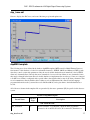
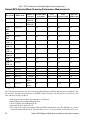
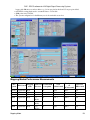
Normal MCA Spectra Mapping Mode.................................................................................................50
Normal MCA Spectra Mode Scanning Performance Measurements...................................................52
Mapping Mode.....................................................................................................................................52
Mapping Modes Performance Measurements......................................................................................53
ii
DXP - EPICS software for XIA Digital Signal
Processing Systems
Release 3-4
December 10, 2014
Mark Rivers
University of Chicago
Contents
• Overview
• Architecture
• EPICS Records, Databases, and medm screens
♦ dxpHighLevel.template
♦ dxpSCA_16.template
♦ dxpLowLevel.template
♦ dxpSystem.template
♦ dxpSaturn.template
♦ Saturn medm screens
♦ dxpMED.template
♦ Multi-element detector medm screens
♦ dxpMapping.template
• Using mapping modes with the xMAP and Mercury
• Installing EPICS
♦ Windows
♦ Linux
♦ vxWorks
• Running
♦ Saturn
♦ xMAP
♦ Mercury
♦ DXP2X
• Performance
Overview
The EPICS DXP module provides support for the digital signal processor based multichannel analyzers from
X-ray Instrumentation Associates (XIA). These devices all contain the functional equivalent of the shaping
amplifier, ADC, and MCA of a conventional pulse-height analysis system. The term "DXP" in this document
stands for Digital X-ray Processor, and refers to all models of the XIA hardware.
DXP supports the following hardware:
DXP - EPICS software for XIA Digital Signal Processing Systems
1
DXP - EPICS software for XIA Digital Signal Processing Systems
• The xMAP, which is a 4-channel PXI card. The PXI crate is typically connected to a Windows PC with a
PCI/PXI fiber-optic bridge, but can also be controlled by a CPU processor card in the PXI crate itself.
• The Mercury (single channel) and Mercury4 (4 channel) standalone desktop units that communicate over
the USB 2.0 port. They both have similar mapping features to the xMAP. Where the term Mercury is used
in this document it applies to both the Mercury and Mercury4 unless otherwise stated.
• The Saturn, which is a standalone desktop unit that communicates over the PC Enhanced Parallel Port
(EPP) or USB port. The Vortex detector from SII (formerly Radiant) is an OEM version of the Saturn,
and it also works with this software.
• The DXP2X, which is a single-width CAMAC module. Each module contains 2 or 4 channels with
similar pulse-processing electronics to the Saturn.
DXP currently supports this hardware under the following operating systems and interfaces:
• The xMAP with the EPICS IOC running on Windows, using the National Instruments PCI/PXI adapter,
or with a CPU card running Windows directly in the PXI crate.
• The Mercury with the EPICS IOC running on Windows or Linux using the USB 2.0 interface.
• The Saturn with the EPICS IOC running on Windows or Linux, using the EPP parallel port, USB 1.0, or
USB 2.0 interfaces.
• The DXP2X with the EPICS IOC running on vxWorks, using the Kinetic Systems 2917/3922 VME to
CAMAC interface. Other CAMAC interfaces that have software support for the ESONE standard
CAMAC library calls should also work, but have not been tested.
On Windows both the EPICS win32-x86 (Microsoft VC++ compiler) and cygwin-x86 (gcc compiler)
architectures are supported.
The features of the EPICS software, compared with software available from XIA are:
• Control and data acquisition are available over the network, from any application or language that
supports the EPICS Channel Access protocol (based on TCP/IP). This means that EPICS clients written
in languages like Python, IDL, LabView, Visual Basic, etc. can control the DXP modules and read the
data. These applications can be running on any computer on the Internet, they do not need to run on the
computer that is attached to the XIA hardware. This client/server model is very desirable in complex data
acquisition environments, such as synchrotron beamlines, because it allows the DXP control and data
acquisition to be integrated with other hardware and software. For example, a control software program
can move a motor, command the DXP to acquire data, and write the data to disk.
• A single software package supports the xMAP, Mercury, Saturn, and DXP2X.
• The Saturn and Mercury can be run from Windows and Linux, while the XIA control programs only run
on Windows.
• The DXP2X support uses the standard XIA Handel library, while the XIA MESA package uses an old
LabView interface.
Architecture
The software consists of the following components:
• An asyn port driver. This driver is implements a class called NDDxp, which is derived from the
asynNDArrayDriver and asynPortDriver base C++ classes. The driver communicates with the hardware
using the XIA Handel library, which in turn communicates with the XIA Xerxes library.
• An EPICS MCA record for each detector. This communicates with the driver via the asyn MCA device
support. This support allows each detector to be treated identically with other supported MCA hardware,
2
Overview
DXP - EPICS software for XIA Digital Signal Processing Systems
such as the Canberra AIM. The MCA record is used for data acquisition in the non-mapping modes, and
to define regions of interest.
• A set of standard EPICS records (ai, ao, bi, bo, waveform, etc.) that are used to set all of the many
software selectable parameters for the DXP, including peaking times, pileup rejection criteria, etc. These
are also used for data acquisition in the mapping modes and to acquire diagnostic data, such as the
baseline histogram and ADC trace. These records use the standard asyn device support.
• A State Notation Language program (dxpMED) for synchronizing acquisition, ROIs, and DXP
parameters in multi-element detector systems.
• Support for the file-saving plugins from the areaDetector package. These plugins are used to stream data
to disk in the mappping modes on the xMAP and Mercury.
• Databases for single-element and multi-element detector systems.
• medm display screens for single-element and multi-element detector systems.
• Example IOC boot directories for the Saturn and Mercury on Windows and Linux, for the xMAP on
Windows, and for the DXP2X on vxWorks.
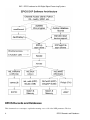
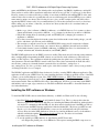
The overall architecture of the EPICS DXP software is shown in the diagram below. At the top level are EPICS
Channel Access client applications, such as the IDL MCA Display program, the IDL Multi-Element Detector
(MED) Display program, medm, spec, and others.
Architecture
3
DXP - EPICS software for XIA Digital Signal Processing Systems
EPICS Records and Databases
This document does not attempt to explain the meaning or use of all of the DXP parameters. The best
4
EPICS Records and Databases
DXP - EPICS software for XIA Digital Signal Processing Systems
documentation of the operation of the DXP modules is provided by XIA in the xMAP User's Manual, Mercury
User's Manual, and the Saturn User's Manual. These manuals all provide an excellent description of the theory of
digital pulse processing as implemented in the DXP models from XIA. They also describe the XIA xManager and
ProSpect software, which can be useful in setting up and testing the hardware, but which do not apply when
running the EPICS software. The xMAP and Mercury manuals also explain the mapping modes that these models
support.
For many parameters in the following databases there is both an EPICS output record (ao, bo, mbbo, etc.) and a
corresponding EPICS input record (ai, bi, mbbi, etc.). The output record is used to set a new value in the DXP
hardware. The input record has an _RBV suffix, which stands for Read Back Value. It is used to read back the
actual value from the hardware, which may be different from the requested value because of limitations of the
hardware, errors, etc.
When the EPICS IOC starts the initial values of the records are set in the following order:
1. The default value in the record definition, typically 0.
2. The value specified in the database file (.template or .substitutions file)
3. The value read back from the hardware or Handel library. This will be the Handel default value, or the
value from the .ini file if it is defined there.
4. The value from save/restore.
5. The value from a "dbpf" in the startup script.
6. The value set from the SNL program on startup.
Steps 1-3 apply to both output records and to input records. Steps 4 and 5 typically only apply to output records,
and step 7 only to input records. If there is no auto_settings*.sav file then most of the DXP parameter records will
obtain their initial values from the .ini file. Thus, by deleting the auto_settings*.sav file one can force EPICS to
use the same parameters that have been saved into an .ini file, for example by xManager or ProSpect.
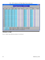
dxpHighLevel.template
The following records are defined in the database dxpHighLevel.template. They control the high-level DXP
parameters such as peaking time, etc. One instance of this database is loaded for each detector channel in the
system. All of the record names in the template file are preceeded by the macro parameters $(P)$(R), where $(P)
is the prefix for this detector system, and $(R) is the name of this specific channel. $(P) should be unique for all
EPICS IOCs on the subnet, and $(R) is typically dxp1:, dxp2:, etc.
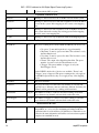
Records in dxpHighLevel.template
Record Name
Record
Type
Description
Trigger Filter Records
TriggerPeakingTime
TriggerPeakingTime_RBV
ao
ai
The peaking time in microseconds for the trigger (fast) filter. The
trigger filter is used to detect input pulses.
TriggerGapTime
TriggerGapTime_RBV
ao
ai
The gap time in microseconds for the fast filter. This gap time is
generally set to 0.
TriggerThreshold
TriggerThreshold_RBV
ao
ai
The threshold in keV for the trigger filter.
dxpHighLevel.template
5
DXP - EPICS software for XIA Digital Signal Processing Systems
Energy Filter Records
PeakingTime
PeakingTime_RBV
ao
ai
The peaking time in microseconds for the energy (slow) filter. The
energy filter is used to measure the energy of the input pulses.
Increasing this time will generally improve the energy resolution at
the expense of decreased throughput.
GapTime
GapTime_RBV
ao
ai
The gap time in microseconds for the energy filter. The gap time is
set to reflect the rise time of the input signal.
EnergyThreshold
EnergyThreshold_RBV
ao
ai
The threshold in keV for the energy filter. This should generally be
set to 0 except for soft x-ray spectroscopy.
MaxWidth
MaxWidth_RBV
ao
ai
Maximum peak width in microseconds for pileup inspection.
Baseline Records
BaselineFilterLength
BaselineFilterLength_RBV
mbbo
longin
The length of the baseline filter in samples. Menu values are powers
of 2 from 8 to 2048.
BaselineThreshold
BaselineThreshold_RBV
ao
ai
The threshold in keV for the baseline filter.
BaselineCutPercent
BaselineCutPercent_RBV
ao
ai
The baseline cut value, in percent units of the baseline histogram.
Baseline values outside the cut range will not be used in computing
the baseline average, but they will still be included in the baseline
histogram. Note: this parameter only applies to the Saturn and
DXP2X, it is not used on the xMAP or Mercury.
BaselineCutEnable
BaselineCutEnable_RBV
bo
bi
A flag to enable or disable the baseline cut. Note: this parameter only
applies to the Saturn and DXP2X, it is not used on the xMAP or
Mercury.
Pre-amp and Energy Range Records
PreampGain
PreampGain_RBV
ao
ai
The gain of the detector pre-amp in mV/keV. Setting this value
accurately is important, because it allows the DXP software to be
correctly internally calibrated. PreampGain should be adjusted so that
the requested MaxEnergy value agrees with the actual energy of the
last MCA channel.
DetectorPolarity
DetectorPolarity_RBV
bo
bi
Pre-amp polarity (not high-voltage polarity). 0=Negative, 1=Positive.
Positive polarity means an x-ray pulse causes an increase in the
pre-amp voltage output. This is normally defined in the .ini file, but
is accessible to EPICS to allow quick determination of the correct
polarity.
ResetDelay
ResetDelay_RBV
ao
ai
For reset pre-amps the time in microseconds to recover after a
pre-amp reset. Note: older xMAPs (before revision D) should use 10
microseconds, newer xMAPs (revision D and later) can use 1
microsecond.
DecayTime
DecayTime_RBV
ao
ai
For RC pre-amps the characteristic decay time in microseconds.
6
dxpHighLevel.template
DXP - EPICS software for XIA Digital Signal Processing Systems
MaxEnergy
MaxEnergy_RBV
ao
ai
The energy of the last channel in the spectrum in keV. If the actual
energy of the last channel, determined by performing an MCA
energy calibration, is not equal to this value, then one should modify
the value of PrempGain.
MCABinWidth_RBV
ai
The width of each bin in the MCA spectrum in keV. This is
computed from PreampGain, MaxEnergy, and the NUSE field of the
MCA record.
ADCPercentRule
ADCPercentRule_RBV
ao
ai
The percent of the range of the input ADC that should be used for
pulses whose energy is at the energy of the CalibrationEnergy, which
the driver automatically sets to be MaxEnergy/2, i.e. the middle
channel of the spectrum. The normal range is 3-10% for reset
pre-amplifiers and 30-50% for RC pre-amplifiers. The goal is to
digitize the baseline noise into a few ADC bits (look at the ADC
trace), but not have the value so large that the input signal drifts out
of the ADC range too often (look at the number of drift ups and drift
downs, NUMDRUPS0 and NUMDRDOS0).
CalibrationEnergy_RBV
ai
The energy at which the ADCPercentRule applies. The EPICS driver
automatically sets this to MaxEnergy/2.
DynamicRange_RBV
ai
The dynamic range of the ADC. This is computed from PreampGain,
MaxEnergy, and ADCPercentRule.
Preset Counting Records
PresetMode
PresetMode_RBV
mbbo
mbbi
The preset counting mode. On the xMAP and Mercury the choices
are:
• "No preset" Count until acquisition is stopped manually.
• "Real time" Count for a preset real time. The real time is set
by the PRTM field of the corresponding MCA record.
• "Live time" Count for a preset live time. The live time is set
by the PLTM field of the corresponding MCA record.
• "Events" The preset number of events is set by the
PresetEvents record.
• "Triggers" The preset number of triggers is set by the
PresetTriggers record.
On the Saturn and the DXP2X only the first 3 choices are available;
"Events" and "Triggers" are not supported.
The preset real time and preset live time are controlled by the .PRTM
and .PLTM fields of the corresponding MCA record.
PresetEvents
PresetEvents_RBV
longout
longin
The number of events to count for. Events are x-rays that were
processed by the energy filter, and includes underflow and overflow
events that are not actually present in the spectrum.
PresetTriggers
PresetTriggers_RBV
longout
longin
The number of triggers to count for. Triggers are x-rays that were
processed by the trigger filter, and includes pileups and other events
that are not actually present in the spectrum.
Counting Statistics Records
dxpHighLevel.template
7
DXP - EPICS software for XIA Digital Signal Processing Systems
ElapsedRealTime
ai
The elapsed real time. This is the same information as in the .ERTM
field of the corresponding MCA record.
ElapsedLiveTime
ai
The elapsed live time. This is the same information as in the .ELTM
field of the corresponding MCA record.
ElapsedTriggerLiveTime
ai
The elapsed live time for the trigger filter.
Triggers
longin
The number of trigger filter events.
Events
longin
The number of energy filter events.
Underflows
longin
The number of underflow events, which are events that would be in
channels less than 0.
Overflows
longin
The number of overflow events, which are events that would be in
channels greater than the last channel in the spectrum.
InputCountRate
ai
The input count rate (ICR), which is the same as
Triggers/ElapsedTriggerLiveTime.
OutputCountRate
ai
The output count rate (OCR), which is the same as
Events/ElapsedRealTime.
Mercury Auxiliary Output Control Records)
TriggerOutput
TriggerOutput_RBV
mbbo
mbbi
The signal to output on the Trigger Output front-panel auxiliary
output line. The choices are:
• Disabled
• Fast Filter
• Baseline Filter
• Energy Filter
• Energy Active
LiveTimeOutput
LiveTimeOutput_RBV
mbbo
mbbi
The signal to output on the Livetime Output front-panel auxiliary
output line. The choices are:
• Disabled
• Fast Filter
• Baseline Filter
• Energy Filter
• Energy Active
Mapping Records (for xMAP and Mercury)
CurrentPixel
longin
The current pixel in the mapping run in MCA mapping and SCA
mapping modes. In List mapping mode this is the number of bytes in
the current mapping buffer. This value applies to the entire moduel,
not to each channel, so it is only updated for the first channel on the
module.
Diagnostic Trace Records
BaselineHistogram
8
waveform
The baseline histogram array. The array is read from the hardware
when this record is processed. The baseline histogram provides a
valuable diagnostic of the electronic noise in the system. It should
dxpHighLevel.template
DXP - EPICS software for XIA Digital Signal Processing Systems
ideally be a perfect Gaussian, with a FWHM equal to the electronic
noise in the baseline. Note: this record should not be processed while
normal data acquisition is in progress or it will slow things down.
BaselineEnergyArray
waveform
The energy values for the baseline histogram. This array is used to
provide a calibrated X-axis when plotting the BaselineHistogram.
TraceMode
TraceMode_RBV
mbbo
mbbi
The type of diagnostic trace information to return in the TraceData
record. On the xMAP and Mercury the choices are:
• "ADC" The equivalent of a digital scope trace of the pre-amp
input to the module.
• "Baseline history" A history of the baseline samples.
• "Trigger filter" The output of the digital trigger filter.
• "Baseline filter" The output of the digital baseline filter.
• "Energy filter" The output of the digital energy filter.
• "Baseline samples" The recent baseline samples.
• "Energy samples" The recent energy samples.
On the Saturn and the DXP2X only the first 2 choices are available,
"ADC" and "Baseline history".
TraceData
waveform
The diagnostic trace data. The array is read from the hardware when
this record is processed. The type of diagnostic trace data to read is
selected with TraceMode, and the time per sample is selected with
TraceTime. Note: this record should not be processed while normal
data acquisition is in progress or it will slow things down.
TraceTime
TraceTime_RBV
ao
ai
The time per sample in microseconds for the TraceData array. The
minimum time depends on the hardware type; it is 0.1 microseconds
for the 20 MHz Saturn and DXP2X, .05 microseconds for the 40MHz
Saturn, and 0.02 microseconds for the xMAP and Mercury.
TraceTimeArray
waveform
The time values for the trace data. This array is used to provide a
calibrated X-axis when plotting the TraceData.
dxpSCA_16.template and dxpSCA_32.template
The following records are defined in the databases dxpSCA_16.template and dxpSCA_32.template. They control
the 16 (Saturn and DXP2X) or 32 (xMAP and Mercury) single-channel-analyzers (SCAs) for each channel. Each
SCA is defined by a low channel and a high channel. In normal MCA Spectra mode the counts in each SCA are
computed by the DXP firmware when acquisition completes. This is essentially the same information as in the
MCA record ROIs. However, the SCAs are also used in the fast SCA mapping mode on the xMAP. In this mode
only the total counts in each SCA are stored at each point in the map. This mode is faster than full spectrum
mapping, and also uses much less disk space. The SCA definitions are also used on the Saturn (when it is
equipped with the optional SCA mapping hardware and firmware) and Mercury for hardware ROI mapping. The
Saturn and Mercury put out a pulse a TTL output line when an x-ray falls within the channel range of that SCA.
This allows very fast mapping, since there is no need to read the spectrum at each point in the scan. The Saturn
has 16 such TTL output lines, the Mercury has 14 lines, and the Mercury4 has 24 lines (6 per channel). Note: in
normal MCA spectra mode SCAs are permitted to overlap in channels. However in the SCA mapping mode and
SCA pulse output mode, the SCA definitions must not overlap. This is because, for performance reasons, each
spectrum channel must be assigned to at most one SCA.
dxpSCA_16.template and dxpSCA_32.template
9
DXP - EPICS software for XIA Digital Signal Processing Systems
One instance of this database is loaded for each detector channel in the system. All of the record names in the
template file are preceeded by the macro parameters $(P)$(R), where $(P) is the prefix for this detector system,
and $(R) is the name of this specific channel.
Records in dxpSCA_16.template and dxpSCA_32.template
Record Name
Record
Type
Description
SCA$(N)Low
SCA$(N)Low_RBV
longout
longin
The low channel for SCA $(N). Actual record names are SCA0Low,
SCA1Low, etc.
SCA$(N)High
SCA$(N)High_RBV
longout
longin
The high channel for SCA $(N). Actual record names are SCA0High,
SCA1High, etc.
SCA$(N)Counts
longin
The total counts for SCA $(N). Actual record names are SCA0Counts,
SCA1Counts, etc.
dxpLowLevel.template
The DXP firmware is actually controlled by a large number of low-level parameters. Each of these parameters is a
16-bit integer. Typically the user will only interact with the high-level parameters described above. But it can
sometimes be useful to read or even modify one of these low-level parameters. The EPICS software provides a
completely generic interface to these low-level parameters. When the driver initializes it queries the names of all
of the low-level parameters, and makes these names available in stringin records. There is a longin record which
provides the current value of each parameter, and a longout record which allows the parameter to be modified.
Note that all parameters have a corresponding longout record, but some parameters are inherently read-only, so
their longout records actually do nothing. The driver currently hardcodes a maximum of 230 low-level
parameters, which is more than the number used by any of the existing firmware (224 is the current maximum, for
the xMAP reset firmware). If a future firmware version has more parameters than this, then a single constant in
the driver will need to be increased, and more records will need to be added to dxpLowLevel.template.
One instance of this database is loaded for each detector channel in the system. All of the record names in the
template file are preceeded by the macro parameters $(P)$(R), where $(P) is the prefix for this detector system,
and $(R) is the name of this specific channel.
Records in dxpLowLevel.template
Record Name
Record Type
Description
NumLLParams
longin
The actual number of low-level parameters.
ReadLLParams
bo
Writing 1 to this record will read all of the low-level parameters
for this channel.
LL$(N)Name
stringin
The firmware name for low-level parameter $(N), N=0 to
NumLLParams-1. Actual record names are LL0Name, LL1Name,
etc.
LL$(N)Val_RBV
longin
The readback value for low-level parameter $(N), N=0 to
NumLLParams-1. Actual record names are LL0Val_RBV,
LL1Val_RBV, etc.
LL$(N)Val
longout
The output value for low-level parameter $(N), N=0 to
NumLLParams-1. Actual record names are LL0Val, LL1Val, etc.
10
dxpLowLevel.template
DXP - EPICS software for XIA Digital Signal Processing Systems
dxpSystem.template
The following records are defined in the database dxpSystem.template. One instance of this database is loaded for
each DXP system, since they control system-wide parameters. This database is loaded for both single-element
(e.g. Saturn and Mercury) and multi-element (e.g. DXP2X, xMAP, and Mercury4) systems. All of the record
names in the template file are preceeded by the macro parameter $(P), the prefix for this detector system.
Records in dxpSystem.template
Record
Type
Record Name
Description
MaxSCAs
longin
The maximum number of SCAs that the system supports. The maximum on
the Saturn and DXP2X is 16, and on the xMAP and Mercury the maximum is
64.
NumSCAs
NumSCAs_RBV
longout
longin
The number of SCAs (ROIs) to use. The records for each SCA are defined in
the database dxpSCA_16.template and dxpSCA_32.template. While the
xMAP and Mercury support 64 SCAs, the dxpMED State Notation Language
program only supports 32. This is because its function is to copy ROIs from
the MCA records to the SCAs in the DXP hardware, and the MCA record
only supports 32 ROIs. Using fewer SCAs reduces the size of the data files in
SCA Mapping mode. Important note: when acquisition completes EPICS
processes the records with the SCA counts (SCA$(N)Counts) if the values
have changed. This can be a very large number of records: for example on a
16-element system if NumSCAs is 32 then 512 records must process if the
SCA data have changed. This was measured to take about 300ms. If very
short acquisition times are being used, and the SCA data are not actually
required by the application, then setting NumSCAs to 1 will signficantly
improve performance.
PollTime
PollTime_RBV
bo
ao
The EPICS driver rapidly polls the hardware when acquisition is active to
detect when acquisition is complete. This record controls the poll time, which
is typically .001 to .01 seconds. Decreasing the time decreases latency at the
expense of more CPU time, and there is a minimum time required to poll the
hardware. Note: polling too fast can overload the system. I recommend 0.001
for the xMAP, 0.005 for the Mercury, and 0.010 for the Saturn.
SaveSystemFile
waveform
The name of a file in which to save the system information. This file is
created by the XIA Handel software, and is the ".ini" file format used in the
call to xiaInit() in the startup script. This file can be used to transfer settings
between XIA's programs (xManager, ProSpect) and EPICS. This is a
waveform record with type DBF_UCHAR and length 256, rather than a
stringout record, so that file paths/names longer than 40 characters can be
used. Client applications must convert the file name to an unsigned char array
when writing to this field.
SaveSystem
SaveSystem_RBV
bo
bi
Writing 1 to this record causes the system information to be written to the file
specified by SaveSystemFile.
EnableClientWait
bo
This record enables waiting for a client when acquisition completes. It can be
used to wait for a client application to save data to disk, etc.
dxpSystem.template
11
DXP - EPICS software for XIA Digital Signal Processing Systems
SetClientWait
bo
This record sets the ClientWait record to Busy if EnableClientWait is set to
Enable. This record is processed by EraseStart and StartAll in the
dxpMED.template database.
ClientWait
busy
This record forces processing to wait until a client clears it after acquisition
starts when EnableClientWait is set to Enable.
dxpSaturn.template
The following records are defined in the database dxpSaturn.template. One instance of this database is loaded for
a Saturn system.
All of the record names in the template file are preceeded by the macro parameters $(P)$(R), where $(P) is the
prefix for this detector system, and $(R) is the name of this specific channel.
• TraceMode. The choices for the TraceMode and TraceMode_RBV records are redefined from those in
dxpHighLevel.template to only include the first 2 choices, e.g. "ADC" and "Baseline history".
• PresetMode. The choices for the PresetMode and PresetMode_RBV records are defined from those in
dxpHighLevel.template to only include "None", "Real time" and "Live time".
• TraceData. The NELM field is redefined from the 4096 value in dxpHighLevel.template to 4000, because
that is the size of the trace array on the Saturn.
• TraceTime. The NELM field is redefined from the 4096 value in dxpHighLevel.template to 4000,
because that is the size of the trace array on the Saturn.
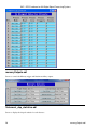
Saturn medm screens
The following is the top-level medm screen for the DXP software. It loads the screens for each of the example
IOCs.
dxpTop.adl
Top-level DXP control screen.
The following are screen shots of the medm screens provided for the Saturn.
dxpSaturn.adl
Main control screen for Saturn.
12
dxpSaturn.template
DXP - EPICS software for XIA Digital Signal Processing Systems
dxpLowLevel.adl
Complete screen for low-level DXP parameters and control.
dxpSaturn.adl
13
DXP - EPICS software for XIA Digital Signal Processing Systems
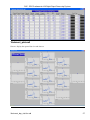
dxp_sca.adl
Screen for SCA display and control.
14
dxpLowLevel.adl
DXP - EPICS software for XIA Digital Signal Processing Systems
mca.adl
Screen to display the spectral data and control acquisition.
dxp_sca.adl
15
DXP - EPICS software for XIA Digital Signal Processing Systems
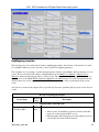
dxp_baseline.adl
Screen to display the baseline histogram and control its update rate.
16
mca.adl
DXP - EPICS software for XIA Digital Signal Processing Systems
dxp_trace.adl
Screen to display the ADC trace, and control the time per point and update rate.
dxpMED.template
The following records are defined in the database dxpMED.template (MED stands for Multi-Element Detector).
One instance of this database is loaded for each multi-element (i.e. DXP2X, xMAP, and Mercury4) DXP system,
since they control system-wide parameters. Only the records in this database that are intended for use by EPICS
clients are documented here. Records that are not intended to be accessed from clients are not documented, since
they may be changed in the future. Records in this database are implemented in several ways. Some are connected
to an MCA record that is configured with a special address that signifies that it controls all detector channels. That
record communicates directly with the driver. Other records are implemented in a State Notation Language
program which monitors the system-wide records like PresetMode, and copies them to the individual detector
records.
All of the record names in the template file are preceeded by the macro parameter $(P), the prefix for this detector
system.
Records in dxpMED.template
Record Name
Record
Type
Description
SNL Status Records
SNL_Connected
dxp_baseline.adl
bi
This record will be 1 ("Connected") when the SNL program has
connected to all of the PVs. If it is 0 ("Not connected") then there is a
17
DXP - EPICS software for XIA Digital Signal Processing Systems
problem with the SNL program.
Acquisition Control Records
EraseAll
bo
Writing 1 to this record erases all of the MCA records in this system.
EraseStart
bo
Writing 1 to this record erases and starts acquisition on all of the MCA
records in this system. In the mapping modes it starts a new mapping
run.
StartAll
bo
Writing 1 to this record starts acquisition on all of the MCA records in
this system without first erasing any existing spectra. In the mapping
modes it starts a new mapping run.
StopAll
bo
Writing 1 to this record stops acquisition in MCA and mapping modes.
Preset Control Records
PresetMode
mbbo
The preset counting mode. On the xMAP and Mercury the choices are:
• "No preset" Count until acquisition is stopped manually.
• "Real time" Count for a preset real time. The real time is set by
the PresetReal record.
• "Live time" Count for a preset live time. The live time is set by
the PresetLive record.
• "Events" The output of the digital baseline filter. The preset
number of events is set by the PresetEvents record.
• "Triggers" The preset number of triggers is set by the
PresetTriggers record.
On the DXP2X only the first 3 choices are available, "Events" and
"Triggers" are not supported. The preset counting modes only apply in
normal MCA Spectra mode, they do not apply in any of the mapping
modes.
PresetReal
ao
The preset real time.
PresetLive
ao
The preset live time. Note that since each channel on a module will
typically have a different count rate (and hence different dead time), the
channels will in general all stop counting at different times.
PresetEvents
longout
The number of events to count for. Note that counting on a module
stops whenever any channel on that module reaches this value.
PresetTriggers
longout
The number of triggers to count for. Note that counting on a module
stops whenever any channel on that module reaches this value.
Status/Statistics Records
StatusAll
ai
ReadAll
ai
18
Processing this record causes the status information (Acquiring,
ElapsedReal, etc.) to be read. For maximum performance with short
count times this record should have .SCAN=Passive. When this record
is Passive the status information will still be read once when acquisition
completes in normal MCA mode.
dxpMED.template
DXP - EPICS software for XIA Digital Signal Processing Systems
Processing this record causes the MCA spectra to be read. For
maximum performance with short count times this record should have
.SCAN=Passive. When this record is Passive the MCA spectra will still
be read once when acquisition completes in normal MCA mode.
However, in order for the MCA spectra update in the MCA mapping
mode this record must be set to periodically process (e.g. "2 second").
Acquiring
bi
Acquisition status, 0=Done, 1=Acquiring. Acquiring will be 1 if any
channel is acquiring.
ElapsedReal
ai
The elapsed real time. This value is the maximum of the elapsed real
time of all system channels.
ElapsedLive
ai
The elapsed live time. This value is the maximum of the elapsed live
time of all system channels.
DeadTime
ai
The dead time. This value is the average of the dead time of all system
channels. The dead time of each MCA is the cumulative dead time since
the MCA was last erased.
IDeadTime
ai
The instantaneous dead time. This value is the average of the
intantaneous dead time of all system channels. The instantaneous dead
time of each MCA is the dead time in the interval since the MCA status
was last read.
High-Level Parameter Records
CopyTriggerPeakingTime
bo
Writing 1 to this record copies the TriggerPeakingTime from channel 1
to all channels.
CopyTriggerGapTime
bo
Writing 1 to this record copies the TriggerGapTime from channel 1 to
all channels.
CopyTriggerThreshold
bo
Writing 1 to this record copies the TriggerThreshold from channel 1 to
all channels.
CopyPeakingTime
bo
Writing 1 to this record copies the PeakingTime from channel 1 to all
channels.
CopyGapTime
bo
Writing 1 to this record copies the GapTime from channel 1 to all
channels.
CopyEnergyThreshold
bo
Writing 1 to this record copies the EnergyThreshold from channel 1 to
all channels.
CopyMaxWidth
bo
Writing 1 to this record copies the MaxWidth from channel 1 to all
channels.
CopyBaselineCutPercent
bo
Writing 1 to this record copies the BaselineCutPercent from channel 1
to all channels.
CopyBaselineCutEnable
bo
Writing 1 to this record copies the BaselineCutEnable from channel 1 to
all channels.
CopyBaselineThreshold
bo
Writing 1 to this record copies the BaselineThreshold from channel 1 to
all channels.
dxpMED.template
19
DXP - EPICS software for XIA Digital Signal Processing Systems
CopyBaselineFilterLength
bo
Writing 1 to this record copies the BaselineFilterLength from channel 1
to all channels.
CopyPreampGain
bo
Writing 1 to this record copies the PreampGain from channel 1 to all
channels.
CopyDetectorPolarity
bo
Writing 1 to this record copies the DetectorPolarity from channel 1 to
all channels.
CopyResetDelay
bo
Writing 1 to this record copies the ResetDelay from channel 1 to all
channels.
CopyDecayTime
bo
Writing 1 to this record copies the DecayTime from channel 1 to all
channels.
CopyMaxEnergy
bo
Writing 1 to this record copies the MaxEnergy from channel 1 to all
channels.
CopyADCPercentRule
bo
Writing 1 to this record copies the ADCPercentRule from channel 1 to
all channels.
Low-Level Parameter Records
ReadLLParams
bo
Writing 1 to this record reads the low-level parameters for all channels.
Note: this record should be set to Passive during normal data
acquisition, or it will slow things down.
Trace and Diagnostic Records
ReadBaselineHistograms
bo
Writing 1 to this record reads the BaselineHistogram for all channels.
Note: this record should be set to Passive during normal data
acquisition, or it will slow things down.
TraceModes
mbbo
This record sets the TraceMode for each channel. On the xMAP and
Mercury the choices are:
• "ADC" The equivalent of a digital scope trace of the pre-amp
input to the module.
• "Baseline history" A history of the baseline samples.
• "Trigger filter" The output of the digital trigger filter.
• "Baseline filter" The output of the digital baseline filter.
• "Energy filter" The output of the digital energy filter.
• "Baseline samples" The recent baseline samples.
• "Energy samples" The recent energy samples.
On the DXP2X only the first 2 choices are available, "ADC" and
"Baseline history".
TraceTimes
ai
The time per sample in microseconds for the TraceData arrays.
ReadTraces
bo
Writing 1 to this record reads the TraceData for all channels. Note: this
record should be set to Passive during normal data acquisition, or it
will slow things down.
ROI and SCA Records
CopyROIChannel
20
bo
dxpMED.template
DXP - EPICS software for XIA Digital Signal Processing Systems
Writing 1 to this record copies all ROIs from channel 1 to all channels
on a channel-by-channel basis.
CopyROIEnergy
bo
Writing 1 to this record copies all ROIs from channel 1 to all channels
on an energy-by-energy basis, i.e. using the energy calibration
information for each MCA.
CopyROI_SCA
bo
Writing 1 to this record copies every ROI for every channel to the
corresponding SCA.
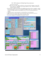
Multi-element detector medm screens
The following are screen shots of the medm screens provided for multi-element detectors, e.g. xMAP, Mercury,
and DXP4C2X.
16element_dxp.adl
Main control screen for 16element system.
16elementFilters.adl
Screen to control DXP filter parameters.
Multi-element detector medm screens
21
DXP - EPICS software for XIA Digital Signal Processing Systems
Screen to control DXP pre-amp and MCA parameters.
22
16elementFilters.adl
DXP - EPICS software for XIA Digital Signal Processing Systems
16element_ROI_SCA.adl
Screen to display ROI and SCA counts for a single ROI/SCA on each detector.
16element_ROI_SCA.adl
23
DXP - EPICS software for XIA Digital Signal Processing Systems
16element_cal.adl
Screen to display energy calibration parameters for each detector.
24
16element_cal.adl
DXP - EPICS software for XIA Digital Signal Processing Systems
16element_dxp_presets.adl
Screen to display presets for each detector.
16element_dxp_presets.adl
25
DXP - EPICS software for XIA Digital Signal Processing Systems
mercuryOutputs.adl
Screen to control the Mercury trigger and livetime auxiliary outputs.
16element_dxp_statistics.adl
Screen to display the elapsed statistics for each detector.
26
mercuryOutputs.adl
DXP - EPICS software for XIA Digital Signal Processing Systems
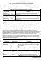
16element_plots.adl
Screen to display the spectral data for each detector.
16element_dxp_statistics.adl
27
DXP - EPICS software for XIA Digital Signal Processing Systems
16element_baseline.adl
Screen to display the baseline histograms and control the update rate.
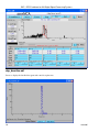
16element_trace.adl
Screen to display the ADC traces, and control the time per point and update rate.
28
16element_baseline.adl
DXP - EPICS software for XIA Digital Signal Processing Systems
dxpMapping.template
The following records are defined in the database dxpMapping.template. One instance of this database is loaded
for an xMAP or Mercury system, since they control system-wide mapping parameters.
This document does not attempt to explain the mapping mode features of the xMAP or Mercury that these records
control. The user should read the chapter on Mapping Mode in the xMAP User's Manual or Mercury User's
Manual to understand the mapping features of these models. The short document on using the Handel library for
mapping mode on the xMAP Handel Quick Start Manual for the xMAP can also be useful. Though the material
discussed there was mostly useful for writing the EPICS driver, it can also help to understand how the system
works.
All of the record names in the template file are preceeded by the macro parameter $(P), the prefix for this detector
system.
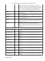
Records in dxpMapping.template
Record Name
Record
Type
Description
Mapping Mode Control Records
CollectMode
CollectMode_RBV
mbbo
mbbi
Selects the collection mode for the system. The choices are:
• "MCA spectra" Normal MCA spectra mode where individual
spectra are collected with the MCA record.
• "MCA mapping" MCA mapping mode where MCA spectra are
collected into the double-buffered memory.
16element_trace.adl
29
DXP - EPICS software for XIA Digital Signal Processing Systems
• "SCA mapping" SCA mapping mode where the total counts in
up to 32 SCAs are collected into the double-buffered memory.
• "List mapping" List-mode mapping mode where the energy of
each x-ray event is collected into the double-buffered memory.
Depending on the value of the ListMode record the time of
each event (20 ns resolution) or the pixel number of each event
is also collected.
Note: the Mercury firmware currently only supports "MCA spectra"
and "MCA mapping" modes.
ListMode
ListMode_RBV
mbbo
mbbi
Selects the list mode variant when CollectMode="List mapping". The
choices are:
• "E & Gate" The Gate input signal is used to advance the pixel
number. The energy and pixel number of each event are
collected into the double-buffered memory.
• "E & Sync" The Sync input signal is used to advance the pixel
number. The energy and pixel number of each event are
collected into the double-buffered memory.
• "E & Clock" The energy and clock time since acquisition was
started (20 ns resolution) are collected into the double-buffered
memory.
PixelAdvanceMode
PixelAdvanceMode_RBV
mbbo
mbbi
Selects the pixel advance mode for system. The choices are:
• "Gate" Transitions on the Gate hardware input signal are used
to drive the pixel advance. On xMAP systems one (and only
one) xMAP module on each PCI bus segment in the system
must be a "gate_master" to use this mode.
• "Sync" Transitions on the Sync hardware input signal are used
to drive the pixel advance. on xMAP systems one (and only
one) xMAP module on each PCI bus segment in the system
must be a "sync_master" to use this mode.
For systems with more than one xMAP module, one module on each
PCI bus segment can be gate_master, another module can be
sync_master, and PixelAdvanceMode can be changed between Gate
and Sync. Note: there is a bug in the current xMAP firmware, so that a
module defined to be a sync_master will always use its pulse input for
pixel_advance, even if another module is defined to be gate_master,
and PixelAdvanceMode is defined to be Gate. This should be fixed in a
future firmware release, but for now if a sync_master is defined in the
system then only use Sync for PixelAdvanceMode.
NextPixel
bo
Writing 1 to this record causes the system to advance to the next pixel
in MCA mapping or SCA mapping modes. This is a "software" pixel
advance, and can be issued any time mapping mode acquisition is in
progress, regardless of the setting of PixelAdvanceMode.
PixelsPerRun
PixelsPerRun_RBV
longout
longin
The total number of pixels to acquire in one "run" when acquisition
starts. If this value is -1 then there is no preset number of pixels, and
30
dxpMapping.template
DXP - EPICS software for XIA Digital Signal Processing Systems
acquisition will continue forever until it is stopped manually with
StopAll. This value only applies in MCA mapping and SCA mapping
modes, not in List mapping mode.
PixelsPerBuffer
PixelsPerBuffer_RBV
longout
longin
The number of pixels per buffer. If AutoPixelsPerBuffer=Manual, then
this value is used, rather than using the maximum possible value
computed when AutoPixelsPerBuffer=Auto. The main reason to set this
value manually is that the updates to statistics and MCA displays in
mapping mode happen only when a buffer is read out. If the time per
pixel is relatively long then decreasing PixelsPerBuffer will result in
more frequent updates of the MCA and statistics displays. Setting this
value too low when doing rapid mapping can result in buffer overflow.
PixelsPerBuffer_RBV always contains the actual number of pixels per
buffer.
AutoPixelsPerBuffer
AutoPixelsPerBuffer_RBV
mbbo
mbbi
Flag controlling how the number of pixels per buffer is determined.
Choices are 0=Manual and 1=Auto. If Manual is selected then the
number of pixels per buffer is controlled by the PixelsPerBuffer record.
If Auto is selected then the maximum number of pixels that the 2MB
mapping buffer can hold is automatically computed.
BufferSize_RBV
longin
The size of the buffer being used in units of 16-bit words. This will be
the first dimension of the array passed to the plugins when a buffer is
read out. The maximum value is 1M=1048576, but it can be less than
this depending on the value of PixelsPerBuffer_RBV.
IgnoreGate
IgnoreGate_RBV
mbbo
mbbi
Flag controlling whether the Gate input signal is used to inhibit
counting. Choices are 0=No and 1=Yes. If IgnoreGate=Yes then the
Gate input can be used as a pixel advance signal, but its high or low
state will not influence whether counting is enabled, i.e. only the
transitions are significant. If IgnoreGate=No then counting will be
inhibited when the Gate input is low (if InputLogicPolarity=Normal) or
high (if InputLogicPolarity=Inverted).
InputLogicPolarity
InputLogicPolarity_RBV
mbbo
mbbi
Flag controlling the polarity of the Gate input signal. Choices are
0=Normal, 1=Inverted. In Normal mode a low level on the Gate input
inhibits counting (if IgnoreGate=No) and a high-to-low transition
performs a pixel advance (if PixelAdvanceMode=Gate). In Inverted
mode these levels are the opposite, i.e. a high level inhibits counting
and a low-to-high transition performs a pixel advance.
SyncCount
SyncCount_RBV
longout
longin
The divisor used on the Sync input for pixel advance if
PixelAdvanceMode=Sync. Allowed values are 1 to 65,535. This value
can be used to divide the Sync clock. For example, if the Sync input
were connected to the pulse output of a stepper motor controller, then
setting SyncCount=10 would perform a pixel advance on every 10'th
stepper motor pulse. SyncCount=1 results in no clock division, i.e.
every Sync input pulse results in a pixel advance.
ReadRate_RBV
ai
The burst read rate in MBytes/s measured when reading the mapping
data from each module.
MBytesRead_RBV
ai
The total number of MBytes of mapping data read from all modules
since the IOC started.
dxpMapping.template
31
DXP - EPICS software for XIA Digital Signal Processing Systems
Parameter Download Control Records
AutoApply
AutoApply_RBV
mbbo
mbbi
Flag controlling whether parameters are automatically downloaded to
the hardware ("apply" operation) each time a parameter is changed, or
whether they are only downloaded when the Apply record is set to 1.
Choices are 0=No, 1=Yes. This flag can dramatically affect
performance, because the process of downloading parameters to the
xMAP or Mercury is very slow, requiring about 0.3 seconds. If many
parameters need to be changed it is much faster to do the following:
1. Set AutoApply=No
2. Change a number of parameters
3. Write 1 to the Apply record
4. Set AutoApply back to Yes
The EPICS driver sets AutoApply=No when the driver is initialized.
This means that all of the parameter setting that occurs during driver
initialization and during iocInit when the records are initialized by
EPICS is very fast because the values are not actually downloaded to
the hardware. At the end of the EPICS startup script there are "dbpf"
commands to write 1 to the Apply record (forcing a download), and to
set AutoApply=Yes. Most operations that the users will do involve
setting a only a few parameters, such as PeakingTime, etc. These are
fast even with AutoApply=Yes, so it is normally left in this state. That
way the user does not have to worry about performing a manual apply
operation with the Apply record. The one operation that does involve
setting a very large number of parameters is processing the
CopyROI_SCA record, which redefines all of the SCAs for each
detector. This is handled by the SNL program, which does the
following:
1. Saves the current state of AutoApply
2. Sets AutoApply=No
3. Copies all of the new SCA parameters for each detector from
the MCA records
4. Writes 1 to the Apply record
5. Sets AutoApply back to previous value
This performance optimization was added in R3-0, and reduces the time
to copy ROIs from several minutes in previous releases to less than 2
seconds in R3-0 for a 16-channel xMAP system.
Apply
32
longout
Writing 1 to this record forces an "apply" operation, downloading the
parameters for all channels to the hardware. This is not needed if
AutoApply=Yes, but it can greatly improve performance to set
AutoApply=No and write to this record after modifying a large number
of parameters.
dxpMapping.template
DXP - EPICS software for XIA Digital Signal Processing Systems
Using mapping modes with the xMAP and Mercury
In the mapping modes on the xMAP and Mercury data are collected into a double-buffered memory on the
module. When one half of the buffer memory is full the EPICS driver reads the data from that buffer into an
NDArray object. It then calls any registered plugins with that NDArray. The plugins will typically be one of the
NDPluginFile plugins which will write the data to disk. The useful file plugins can write the data in netCDF,
NeXus/HDF5, and TIFF formats. The JPEG plugin will not be useful, because the data are not images. The data
can also be passed to the NDPluginStdArrays plugin which can make the data available to EPICS channel access
clients as waveform records.
The data in each NDArray object is a 16-bit unsigned integer array with dimensions [BufferSize,
ModulesPerSystem]. BufferSize is the size of the double-buffered memory in use, which is controlled by the
AutoPixelsPerBuffer and PixelsPerBuffer records. It has a maximum value of 2^20 (1048576) but can be smaller
than this. ModulesPerSystem is the total number of xMAP modules in the system, and is always 1 for the
Mercury. In MCA mapping and SCA mapping modes the buffer for each module in this array contains the data
for each pixel, including the elapsed live and real time, triggers and events, and the MCA or SCA data. In List
mapping mode the buffer contains the event data for each x-ray event. The details of the buffer structure are
beyond the scope of this document, but the buffer structure is thoroughly described in the section entitled
"Mapping Mode Data" in the xMAP User's Manual and Mercury User's Manual.
The EPICS software does not provide records to configure the Gate, Sync, or LBUS masters in the system. This is
because there can be a variable number of these depending on how many PCI bus segments the xMAPs use. The
Gate, Sync, and LBUS masters should be configured with the xManager configuration wizard, or by directly
editing the .ini file. The values for the masters in the .ini file will be used, EPICS does not modify them.
The following medm screen is used to configure the mapping modes on the xMAP and the Mercury.
mappingControl.adl
Using mapping modes with the xMAP and Mercury
33
DXP - EPICS software for XIA Digital Signal Processing Systems
The following medm screen is used to configure the netCDF file plugin to save mapping mode data on the xMAP
and the Mercury.
NDFileNetCDF.adl
34
mappingControl.adl
DXP - EPICS software for XIA Digital Signal Processing Systems
To collect mapping mode data one would typically execute the following steps:
1. Select the mapping mode (CollectMode record)
2. In MCA mapping and SCA mapping modes:
♦ Select the pixel advance mode (PixelAdvanceMode record)
♦ Select the number of pixels per run (PixelsPerRun record)
3. In List Mapping mode:
♦ Select the list mode variant (ListMode record)
4. In the netCDF plugin
♦ Set the Enable record to Enable.
♦ Set the FilePath, FileName, FileNumber, FileTemplate, AutoIncrement, FileWriteMode,
NumCapture, and Autosave records to the desired values. Typically AutoIncrement=Yes,
FileWriteMode=Stream, NumCapture= number of buffers to be captured =
PixelsPerRun/PixelsPerBuffer.
♦ If FileWriteMode is Stream or Capture then start capture/streaming with the Capture record.
NOTE: Before stream or capture can be started there must have been at least 1 callback to the
plugin in the current mapping mode with the same CollectMode and PixelsPerBuffer currently in
use. This is because stream and capture modes need to know the buffer size that will be received
at the time that capture/streaming is started. This can be done by simply enabling the file plugin
and doing a quick run. Just start a run, advance a few pixels with the NextPixel record, and stop
the run. Even though only a few pixels have been collected the entire buffer is read out, so the
size is correct.
5. Start acquisition with the EraseStart record.
6. In MCA mapping or SCA mapping modes do something that causes the pixels to advance. This could be
using the NextPixel record, or an external advance source such as a pulse generator, motor pulse train,
etc. In List mapping modes the buffer fills up with event data even if the Sync or Gate pixel clock is not
advancing.
7. Each time a buffer fills up the netCDF plugin will be called, writing data to disk.
8. In MCA mapping mode each time the buffer fills up the MCA spectra for the first pixel in that buffer will
be sent to the MCA records, so they can be displayed. This provides a periodic visual feedback on the
NDFileNetCDF.adl
35
DXP - EPICS software for XIA Digital Signal Processing Systems
MCA data.
9. In MCA and SCA mapping modes once the requested number of pixels per run has occured acquisition
will automatically stop. In List mapping mode acquisition must be manually stopped with the StopAll
record.
10. If the netCDF plugin is in stream or capture mode and NumCapture was specified correctly, then it will
also automatically stop capturing when the last buffer is received. If NumCapture was 0 or was too large,
then stream/capture should be manually stopped by writing 0 to the Capture record.
Data acquisition in mapping mode is very flexible. When doing a 2-D map, for example, one could stream the
data for the entire map into a single large netCDF file. Alternatively, one could save just a single scan row into
each file, and restart the file plugin for each row, using a new file name, or auto-increment on the file number.
Data can also be saved into NeXus or TIFF files, rather than netCDF files.
Which mapping mode to use depends on the needs of the experiment. If only the counts in ROIs are needed then
it is most efficient to collect data in SCA mapping mode. The counts in the SCAs are the total counts, with no
background subtraction. However, it is possible to define additional SCAs in regions of no peaks, and correct for
background during post-processing by using these "background" SCAs to estimate the background counts per
channel. List mapping mode can be used to collect data with very high time resolution (20 ns). It is also often
more faster and more efficient in disk space than MCA mapping mode, with essentially the same information. The
speed and file size in List mapping mode depends of course on the number of x-rays per second. Each x-ray event
requires 6 bytes (2 for the x-ray energy, and 4 for the clock time or pixel number). Consider a 4-detector xMAP
system with a count rate of 100,000 cps per detector. The total data rate in List mapping mode will be 4 detectors
* 100,000 events/s * 6 bytes/event = 2.4 MB/sec. That can be compared to running the same system in MCA
mapping mode with 2048 channel spectra at the fastest possible pixel rate, 1000 pixels/s. In that case the data rate
is 4 detectors * 2048 channels * 2 bytes/channel * 1000 pixels/s = 16MB/s. In this case List mapping results in
almost 7 times less data than MCA mapping, because most of the spectral channels are 0 in MCA spectra mode.
The only significant difference is that in list mode there is no measure of live time at each "pixel", and it will
require more post-processing to arrange the data into spectra, if that is what is desired.
This is a Python program called fast_mapping.py that implements such a 2-D scan. This is a simple program that
was written by Yan Fen and me at the SSRF (Shanghai Synchrotron). It works as follows:
• The system contains an SIS3820 multi-channel scaler. This has its external channel advance connected to
the stepper motor pulses driving the X sample stage. The External Prescale is set to divide these pulses by
the number of motor pulses per pixel. Each time the X stage motor moves by this amount the SIS3820
collects the data from the ion chamber (I0) and other counter inputs into its MCA records. It also outputs
a trigger pulse on its CIP output, which is input into the xMAP Sync input to do a pixel advance on the
xMAP.
• There are 2 EPICS sscan records.
♦ X15U1:test:scan1 is the fast inner scan. It drives the X stage motor. It is configured to collect 1-D
arrays, which are the SIS3820 MCA records. These are saved into MDA files by the saveData
utility in EPICS. It has detector triggers for the SIS3820 EraseStart PV. However, this is just to
forces the sscan record wait until the SIS3820 is done at the end of the row. It is actually
necessary to start the SIS3820 and xMAPs before the scan starts. This is because the sscan record
begins moving the motor before it fires its detector triggers, and that will not work here, they
need to start counting before the motor starts moving. When each row is collected this scan is
started by the Python script. It will save the SIS3820 counters into a separate MDA file for each
row, because it does not think a 2-D EPICS scan is in progress.
♦ X15U1:test:scan2 is the slow outer scan. Its positioner is the Z stage motor. However, we are
only using this scan as a convenient place for the user to enter the start, end, step size and number
of points of the Z scan. This scan record is not actually executed. Rather the Python program
36
NDFileNetCDF.adl
DXP - EPICS software for XIA Digital Signal Processing Systems
reads the PVs for this scan and moves the motor itself. The reason for this is that there are things
that need to be done at the start of each row that are much more easily done in the Python
program than in the sscan record. This includes setting up the netCDF file plugin, starting the
SIS3820 and xMAP, etc.
• At the very beginning of the 2-D scan the Python code does the following:
♦ Reads the size of the scan in the X and Z directions (nFast, nSlow) from the sscan records.
♦ Writes nFast into the NuseAll PV of the SIS3820 so that it stops after this many channel
advances. It also writes nFast into the xMAP PixelsPerRun PV to set the number of pixels per
run.
♦ Computes the number of xMAP buffers that each scan row will require. This is ((nFast+1)/124 +
1), because each buffer can hold 124 pixels when collecting 2048 channel spectra. (To be more
general it should read the value of PixelsPerBuffer from the xMAP rather than hardcoding 124).
Writes this value into the NumCapture PV of the netCDF plugin.
♦ Writes the desired base file name into the FileName PV of the netCDF plugin.
♦ Writes 1 into the FileNumber PV of the netCDF plugin. The netCDF file plugin was also
previously configured to have a valid FilePath, AutoIncrement=Yes, and
FileTemplate="%s%s_%d.nc". It was thus saving files with names like MyScan_1.nc,
MyScan_2.nc, ... for rows 1, 2, ... of the scan.
♦ Sets the netCDF file plugin FileWriteMode PV to Stream (choice 2). This means that all of the
pixels for one scan row will be streamed into a single netCDF file.
• The Python program then executes a 1-D loop over the number of rows (Z stage pixels) in the scan. For
each row of the scan it does the following:
♦ Starts the netCDF plugin streaming by writing 1 to the Capture PV.
♦ Sets the speed of the X stage motor to its fast flyback speed.
♦ Starts the X stage moving to the start position.
♦ Starts the Z stage moving to the position for this row.
♦ Waits for the X and Z stages to arrive at their target positions.
♦ Sets the speed of the X stage motor to the desired scan speed (i.e. pixel size / time per pixel).
♦ Erases and starts the SIS3820.
♦ Erases and starts the xMAP. Waits 0.5 seconds after this to allow the xMAP to be ready.
♦ Starts the fast scan (scan 1). That will start the X stage moving, and will wait for the SIS3820 to
complete. saveData will write the SIS3820 MCA data to the MDA file at the end of the scan row.
♦ Waits for the xMAP to be done.
There are IDL functions available in the CARS IDL detector package to conveniently extract the MCA, SCA, or
List mode data from netCDF files produced with the netCDF plugin. read_xmap_netcdf.pro reads mapping data
from a single netCDF file. It calls read_nd_netcdf.pro and decode_xmap_buffers.pro. read_xmap_2d.pro is an
IDL procedure that calls read_xmap_netcdf.pro to read all of the netCDF files for an entire 2-D scan collected by
programs such as the Python program described above.
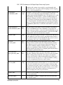
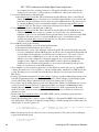
The following is an IDL program that calls read_xmap_2d for a 501x500 scan of a Ni mesh. It extracts the Ni Ka
peak (channels 716 to 776) from the data. It sums over all the channels in this region, normalizes by live time,
sums over all 7 detectors, and finally displays the image with the IDL iTools iimage procedure.
; Read data, only channels 716 to 776
d = read_xmap_2d('Scan4_', 501, live_time=live_time, real_time=real_time, $
events=events, triggers=triggers, channel=[716,776])
; Sum over channels 716 to 776 (first dimension)
tot = total(d, 1)
; Divide by live time for each detector for each pixel, but live=0 increase to .001
tot1 = tot/(live_time>.001)
; Sum over the detectors
NDFileNetCDF.adl
37
DXP - EPICS software for XIA Digital Signal Processing Systems
tot2 = total(tot1, 1)
; Display
iimage, tot2
end
This scan was done at SSRF with the following parameters:
• 1x1 micron pixels.
• 500x501 pixel scan.
• 2.5 ms per pixel
• 7-element Si(Li) detector with 2 xMAP modules.
• Total scan time was 38 minutes
This is the image produced from the "iimage" command in the above program after interactively adding some
annotation.
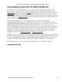
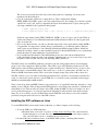
This is another example of a scan done at SSRF of a mouse spleen with the following parameters:
• 3x3 micron pixels.
• 530x647 pixel scan.
38
NDFileNetCDF.adl
DXP - EPICS software for XIA Digital Signal Processing Systems
• 20 ms per pixel
• 7-element Si(Li) detector with 2 xMAP modules.
• Total scan time was 178 minutes
This is the image produced by summing over the counts in the channel regsions for K, Fe, and Zn. The image in
the lower right is a visible light image from the sample microscope.
NDFileNetCDF.adl
39
DXP - EPICS software for XIA Digital Signal Processing Systems
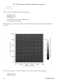
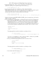
This spectrum of a 10x10 pixel region high in Zn in the above image. It was produced by reading the entire
spectrum for 10x10 pixel region and then summing over all 100 pixels, and then summing over all 7 detectors.
40
NDFileNetCDF.adl
DXP - EPICS software for XIA Digital Signal Processing Systems
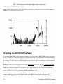
This is an example of decoding the buffers in IDL for List Sync mode data. It computes and plots the histogram
(spectrum) of all of the events.
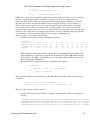
IDL> buff = read_nd_netcdf('list_mapping_sync_001.nc')
IDL> help, buff
BUFF
INT
= Array[1048576, 4]
IDL> d = decode_xmap_buffers(buff)
IDL> help, /structure, d
** Structure XMAPLISTDATA, 8 tags, length=32, data length=32:
LISTMODE
LONG
1
PDATA
POINTER
<ptrheapvar17>
PPIXELCLOCK
POINTER
<PtrHeapVar18>
PNUMEVENTS
POINTER
<PtrHeapVar19>
PREALTIME
POINTER
<PtrHeapVar20>
PLIVETIME
POINTER
<PtrHeapVar21>
PINPUTCOUNTS
POINTER
<PtrHeapVar22>
POUTPUTCOUNTS
POINTER
<PtrHeapVar23>
IDL> help, *d.pData
<PtrHeapVar17> INT
= Array[349525, 4]
IDL> help, *d.pPixelClock
<PtrHeapVar18> LONG
= Array[349525, 4]
IDL> help, *d.pRealTime
<PtrHeapVar20> FLOAT
= Array[16]
IDL> h = histogram((*d.pData) and 8191)
NDFileNetCDF.adl
41
DXP - EPICS software for XIA Digital Signal Processing Systems
IDL> iplot, h, yrange=[1,1e3], /ylog
This is the histogram (spectrum) of all of the events for all detectors. Note that bits 13 and 14 (detector channel
number 0-3) for each event are masked off.
Installing the EPICS DXP software
To install the EPICS DXP software first decide whether you want to build the EPICS DXP software from source
code, or install the pre-built binaries. Most users will just download the pre-built binaries. The Windows binaries
should run on almost any version of Windows. The Linux binaries are built with Redhat Fedora kernel 2.6.27 and
gcc version 4.3.0. These binaries should run on many recent versions of Linux, but this has not been extensively
tested.
Building from the source code requires downloading EPICS base and all of the required synApps components.
To build from source code on Windows for the win32-x86 architecture requires Microsoft Visual Studio .NET
2003 or later, plus perl and make. To build from source code on Windows for the cygwin32-x86 architecture
requires the gcc, g++, perl and make packages from Cygwin. It is beyond the scope of this document to describe
how to build the source code. Consult other EPICS documentation for this.
The DXP software provides example IOC directories, iocBoot/iocSaturn, iocBoot/iocXMAP,
iocBoot/iocMercury, and iocBoot/iocDXP2X. These create EPICS process variables with names like
dxpSaturn:dxp1.PKTIM, where dxpSaturn is the "prefix" for the process variable names, dxp1 is the DXP record
42
Installing the EPICS DXP software
DXP - EPICS software for XIA Digital Signal Processing Systems
name, and PKTIM is the field name. The default prefixes are dxpSaturn:, dxpXMAP:, dxpMercury, and dxp2X:.
These prefixes would be OK for installations where there will be at most one IOC of a given type on the subnet.
However, in many cases there will be the possibility of more than one DXP module running EPICS on the same
subnet. If this is the case then it is essential that each one use a different prefix, because EPICS process variable
names must be unique on a subnet. The following is how to give your IOC a unique prefix, and still be able to
upgrade the EPICS software easily. It is recommended that you follow these instructions even if you don't have
name conflicts on your subnet, so that files you edit are in a directory that will not be overwritten when you
upgrade the EPICS software.
• Make a copy of the iocSaturn, iocXMAP, iocMercury, or iocDXP2X directory. Let's assume you have a
Saturn and will make your prefix be APSSat1:, so a good name for the directory would be iocAPSSat1.
• Edit all files in that directory (including st.cmd, and START_IOC*), changing all occurances of
dxpSaturn: to APSSat1:.
• If you have created any higher-level medm screens that load the medm screens in this package, you will
need to edit them to pass the new prefix, APSSat1:
• The next time you unpack a new version of the EPICS DXP software it will overwrite the iocSaturn
directory. However, if you have made your own new directory, APSSat1/, that will not be modified.
• For the multi-element systems (iocXMAP, iocMercury, iocDXP2X) the files to be edited include, for
example, 4element.cmd, 4element.substitutions, and START_EPICS.
The EPICS DXP application uses the EPICS save/restore facility. This means that all of the important parameters
that you might change when running the DXP software are saved in files in the subdirectory called autosave/
under your IOC directory. These parameters include the peaking time, the update rates for displays and many
other parameters. The next time EPICS is started it will restore these values automatically from the file called
autosave/auto_settings.sav. On multi-element systems the files are called auto_settings4.sav, or
auto_settings16.sav, etc. It is a good idea to make copies of this file from time to time so that you can get back to
old settings if the file is lost or corrupted.
The DXP IOC application and EPICS clients both need to be able to start the EPICS caRepeater application. This
application is built as part of EPICS base. If you are installing the Linux or Windows prebuilt versions of the DXP
software you can obtain caRepeater as part of the EPICS WIN32 binaries or EPICS Linux binaries from our
Web site. Unpack these directories into a directory on your computer, and put that directory into your PATH
environment variable. That way EPICS will be able to find caRepeater. It will also provide many useful EPICS
shell utilities, such as caput, caget, camonitor, etc. The IDL ezcaIDL.dll and ezcaIDL.so shareable libraries are
also in that distribution.
Installing the DXP software on Windows
To install the EPICS DXP software with a Saturn, Mercury, or xMAP on a Windows PC do the following:
• Install the Windows Port IO Driver from Scientific Software Tools. This is a software driver that lets
Windows applications communicate with I/O ports, including the Enhanced Parallel Port. Although this is
only needed to communicate with the EPP port, the driver must be installed even if the EPP port will not
be used, because the EPICS dxpApp application is linked with that DLL. The driver (port95NT.exe and
dlportio.sys) is also included in the handelSrc/ (source version) and bin/win32-x86 (pre-built binary
version) directories in the DXP distribution. It can also be found in the Handel source code distribution
which is available through the XIA software downloads Web site. The driver is found in the
redist/drivers/usb1 directory.
• To use the parallel port (EPP) interface on older Saturns and SII Vortex units:
♦ Configure the parallel port to be in EPP mode. This requires entering the BIOS setup screen on
Installing the DXP software on Windows
43
DXP - EPICS software for XIA Digital Signal Processing Systems
the computer before the operating system boots. The menus will differ from one computer to
another, but it is necessary to set the parallel port to EPP mode. Other modes will not work.
• To use the USB 1.0 interface with the Saturn:
♦ Install the ProSpect from XIA. This will install the required Windows driver for the USB 1.0
Saturn. The driver (ezusb.sys, xiausb.inf) is also included in the handelSrc/ (source version) and
bin/win32-x86 (pre-built binary version) directories in the DXP distribution. The driver can also
be found in the Handel source code distribution which is available through the XIA software
downloads Web site. The driver is found in the redist/drivers/usb1 directory.
• To use the USB 2.0 interface with the Saturn or Mercury:
♦ Install the ProSpect from XIA. This will install the required Windows EZ-USB driver for the
USB 2.0 Saturn. The driver (cyusb.sys, cyusbme.sys, xia_usb2.inf) is also included in the
handelSrc/ (source version) and bin/win32-x86 (pre-built binary version) directories in the DXP
distribution. The driver can also be found in the Handel source code distribution which is
available through the XIA software downloads Web site. The driver is found in the
redist/drivers/usb2 directory.
• For an xMAP system do the following:
♦ Install the PCI/PXI converter from National Instruments.
♦ Install the National Instruments driver software.
♦ Install the latest version of the xManager software from XIA. This will install the Plx driver that
is used to communicate with the xMAP modules. It will also run a Configuration Wizard that will
create an initial .ini file with the correct PCI bus and slot addresses for your system. You can
copy that file to the iocXMAP directory or edit one of the .ini files there that most closely
matches your system configuration (xmap4.ini, xmap8.ini, etc.). It is useful to have xManager
available on the computer to compare with the EPICS software. The driver (Plx9054.sys,
xia9054.inf) is also included in the handelSrc/ (source version) and bin/win32-x86 (pre-built
binary version) directories in the DXP distribution.
• Chose whether to use the Cygwin (cygwin-x86) or native Windows (win32-x86) version of the EPICS
software. The main reason to use Cygwin is to run the saveData utility, which will save EPICS scan data
to disk. This utility does not currently run under the native Windows version because it lacks the Sun
RPC library.
• If using Cygwin then install the basic Cygwin package. Cygwin is a public domain package that provides
Unix-like programming libraries and commands on Windows. When using the Cygwin install program
use all of the default settings, which will install just the basic package into C:\Cywgin.
• If you want to run the medm display program on the Windows PC, which is recommended in most cases,
you need to install Exceed. Exceed is a commercial X-Windows package from Hummingbird. After
installing Exceed you need to install the EPICS Win32 Extensions, which contain medm. Note that
medm works with some non-commercial versions of X windows servers for Windows, but Exceed is
guaranteed to work.
• Download the latest standalone release of the EPICS DXP software, containing Cygwin and native
Windows binaries.
• Unpack that distribution into a directory such as C:\EPICS or C:\Program Files\EPICS. The distribution
file, dxpStandlone_XXX.tgz can be unpacked using WinZip, or with the gunzip and tar utilities that come
with Cygwin. To use the Cygwin tools:
$ cd /cygdrive/c/epics
# Or wherever you have chosen to put the EPICS software
$ tar xzvf dxpStandalone_3-0.tgz
# Unpack the tar file.
• Make sure that the .bat files in iocBoot/ioc*/ have execute permission. This can be done by running the
Cygwin bash shell and typing
$ cd iocBoot/iocSaturn
$ chmod +x *.bat
44
Installing the DXP software on Windows
DXP - EPICS software for XIA Digital Signal Processing Systems
This is necessary because these files may not have this permission, depending on how they were
unpacked from the distribution.
• Copy all of the medm .adl files into a single directory. This is simpler than defining
EPICS_DISPLAY_PATH to point to all of the required directories. For example, if you decide to put the
.adl files in C:\epics_adls, and if you unpacked the dxp tar file distribution into C:\epics, then type the
following commands at the Cygwin bash shell prompt:
$ mkdir /cygdrive/c/epics_adls
$ find /cygdrive/c/epics -name '*.adl' -exec cp -f -p -v {} /cygdrive/c/epics_adls \;
Define the environment variable EPICS_DISPLAY_PATH to point to C:\epics_adls. For the Windows
shell use the Windows Control Panel/System/Advanced/Environment Variables. For the Cygwin shell
edit your .bashrc file.
• If you look at that batch file, you will see a line that temporarily sets the environment variable PATH to
C:\cygwin\bin. You may want to add this directory permanently to your Windows path for Windows
shells. Again, use the Windows Control Panel/System/Advanced/Environment Variables. Modify the
definition according to where you have installed Cygwin. Note that the PATH will be set to automatically
include that directory when running the Cygwin bash shell.
• If you installed pre-built binaries, rather than building from source, then edit the envPaths file in
iocBoot/iocSaturn. Change the paths to the locations of the directories on your system. Don't worry about
the path for directories that don't exist, like SNCSEQ, EPICS_BASE, etc.
The DXP software uses the EPICS areaDetector module for the file-saving plugins that are used in mapping
modes. Some of these plugins use Windows DLLs. These DLLs are provided with the prebuilt version of the
DXP software, in the areaDetector/bin/win32-x86 or cygwin-x86 directories. Windows needs to be able to find
these DLLs when you run the DXP software. The easiest way to do this is to put the path to the DLLs in your
Windows PATH environment variable. This is done in the example startup scripts in the iocBoot directories.
The XIA software is very slow when downloading the firmware files (.fdd files) to the hardware when the files
reside on a remote file system. It is best to put the FDD files on a local file system, particularly when using an
xMAP system with multiple xMAP modules.
There is a known problem with EPICS clients losing connections to a Cygwin IOC when they subscribe to a large
number of array callbacks. This can happen with DXP application, since clients may subscribe to callbacks from
many MCA records. This can affect any client, such as IDL, medm, the EPICS sscan record, Python, etc. It is a
serious problem that appears to be a bug in Cygwin itself. Hopefully it will be tracked down and fixed in the
future. If you do not need to use the saveData function in the DXP IOC itself, then you can work around this
problem by using the win32-x86 version of the DXP software.
Installing the DXP software on Linux
To use the EPICS DXP software with a Saturn or Mercury on a Linux computer do the following:
• To use the USB 1.0 or USB 2.0 interface:
♦ Install the latest version (0.1.12 or later) of libusb from SourceForge. This software must be
installed using the root account. The version of libusb that comes with some Linux systems is
older, and often will not work, so install this more recent version.
• Download the latest standalone release, of the EPICS DXP software, containing Linux binaries.
Installing the DXP software on Linux
45
DXP - EPICS software for XIA Digital Signal Processing Systems
• Unpack that distribution into a directory such as /usr/local/epics. The distribution file,
dxpStandalone_XXX.tgz can be unpacked using the Linux tar utility, e.g.:
tar xvzf dxpStandalone_3-0.tgz
• Copy all of the medm .adl files into a single directory. This is simpler than defining
EPICS_DISPLAY_PATH to point to all of the required directories. For example, if you decide to put the
.adl files in /home/epics/epics_adls, and if you unpacked the dxp tar file distribution into
/home/epics/epics, then type the following commands at the shell prompt:
$ mkdir /home/epics/epics_adls
$ find /home/epics/epics -name '*.adl' -exec cp -f -p -v {} /home/epics/epics_adls \;
Define the environment variable EPICS_DISPLAY_PATH to point to /home/epics/epics_adls. Do this by
editing your .cshrc or .bashrc file.
• Access to the EPP I/O port on Linux requires root privilege. This can be done in any of following 3 ways:
1. Prefered method. The EPICS DXP software on Linux contains a program called startWithIopl3.
This program calls iopl(3) as root, and then reverts back to the non-root account to run dxpApp.
NOTE: This method does not work on some versions of Linux, probably because of SELinux
protections that prevent processes started with execv() from inheriting the iopl(3) permissions. To
use this method the application startWithIopl3 must be installed as suid root. Do this as follows:
> cd bin/linux-x86
> su root
(password)
> chmod +s startWithIopl3
> exit
The dxpApp application can then be run without root privilege as follows:
> cd iocBoot/iocSaturn
> ../../bin/linux-x86/startWithIopl3 ../../bin/linux-x86/dxpApp st.cmd
You can also copy startWithIopl3 to a directory like /usr/local/bin or ~/bin that is in your PATH.
That way it can be run without having to specify the path.
2. Not as good. Install the dxpApp application as suid root. Do this as follows:
> cd bin/linux-x86
> su root
(password)
> chmod +s /bin/linux-x86/dxpApp
> exit
The dxpApp application can then be run without root priviledge as follows:
> cd iocBoot/iocSaturn
> ../../bin/linux-x86/dxpApp st.cmd
3. Least desirable method. Run dxpApp as root:
> cd iocBoot/iocSaturn
> su root
46
Installing the DXP software on Linux
DXP - EPICS software for XIA Digital Signal Processing Systems
(password)
> ../../bin/linux-x86/dxpApp st.cmd
or
> sudo ../../bin/linux-x86/dxpApp st.cmd
• USB devices on Linux are automatically created with read-only permission for non-root users by default.
In order to run the dxpApp application without root privilege it is necessary to change the device
permissions. Because these devices are created dynamically when the Saturn or Mercury is connected,
this cannot just be done once statically. Rather it requires using the "hotplug" or "udev" facilities on
Linux to have the device permissions set correctly each time the device connects. More recent Linux
kernels use the "udev" facility, older kernels use the "hotplug" facility. I do not know exactly which
kernel version the switch to udev was done, but I do know from my systems that 2.6.9 uses hotplug while
2.6.22 uses udev. If the directory /etc/hotplug exists then the system is presumably using hotplug. In that
case the directory /dev/bus/usb will probably not exist, only /proc/bus/usb will exist.
Here is a recipe for older systems using hotplug.
1. Add the following lines to the file /etc/hotplug/usb.usermap
# XIA Saturn
usbsaturn 0x0003
usbsaturn 0x0003
usbsaturn 0x0003
usbsaturn 0x0003
0x10e9
0x10e9
0x10e9
0x10e9
0x0700
0x0701
0x0702
0x0703
0x0000
0x0000
0x0000
0x0000
0x0000
0x0000
0x0000
0x0000
0x00
0x00
0x00
0x00
0x00
0x00
0x00
0x00
0x00
0x00
0x00
0x00
0x00
0x00
0x00
0x00
0x00
0x00
0x00
0x00
0x00
0x00
0x00
0x00
These lines instruct the hotplug facility to run the script /etc/hotplug/usb/usbsaturn whenever the
Saturn or Mercury is added to the system. 10e9 is the vendor ID for XIA. 0700 and 0701 are the
product IDs for the USB 1.1 and USB 2.0 versions of the Saturn. 0702 and 0703 are the product
IDs for the Mercury and Mercury4.
2. Create the file /etc/hotplug/usb/usbsaturn containing the following lines:
#!/bin/bash
if [ "${ACTION}" = "add" ] && [ -f "${DEVICE}" ]
then
chmod 666 "${DEVICE}"
fi
This script tells hotplug to set the permissions on the XIA USB device to 666 (owner, group, and world
read/write):
[root@vincent usb]# ls -lt /proc/bus/usb/001/021
-rw-rw-rw- 1 root root 134 Jan 8 12:20 /proc/bus/usb/001/021
Here is a recipe for newer systems using udev.
1. Create a file in /etc/udev/rules.d called, for example, "80-saturn.rules". Put the following lines in
this file.
SUBSYSTEM=="usb",ACTION=="add",ATTRS{idVendor}=="10e9",ATTRS{idProduct}=="0700",MODE="0
SUBSYSTEM=="usb",ACTION=="add",ATTRS{idVendor}=="10e9",ATTRS{idProduct}=="0701",MODE="0
SUBSYSTEM=="usb",ACTION=="add",ATTRS{idVendor}=="10e9",ATTRS{idProduct}=="0702",MODE="0
SUBSYSTEM=="usb",ACTION=="add",ATTRS{idVendor}=="10e9",ATTRS{idProduct}=="0703",MODE="0
Installing the DXP software on Linux
47
DXP - EPICS software for XIA Digital Signal Processing Systems
These rules instruct the udev facility to set the permissions on the USB device to 666 (owner,
group and world read/write) for the Saturn or Mercury whenever it is added to the system. 10e9 is
the vendor ID for XIA. 0700 and 0701 are the product IDs for the USB 1.1 and USB 2.0 versions
of the Saturn. 0702 and 0703 are the product IDs for the Mercury and Mercury4. Note that the
10e9 ID is case sensitive!
Note that the Linux "udev" facility has been evolving quite rapidly. The above lines work on a
relatively recent Linux kernel (2.6.27). On older kernels the following syntax was required:
SUBSYSTEM=="usb_device",ACTION=="add",SYSFS{idVendor}=="10e9",SYSFS{idProduct}=="0700",MODE="0
SUBSYSTEM=="usb_device",ACTION=="add",SYSFS{idVendor}=="10e9",SYSFS{idProduct}=="0701",MODE="0
SUBSYSTEM=="usb_device",ACTION=="add",SYSFS{idVendor}=="10e9",SYSFS{idProduct}=="0702",MODE="0
SUBSYSTEM=="usb_device",ACTION=="add",SYSFS{idVendor}=="10e9",SYSFS{idProduct}=="0703",MODE="0
In the older version the SUBSYSTEM is "usb_device" rather than "usb", and the SYSFS keyword
rather than ATTRS is used.
2. Force the udevd daemon to reload its rules:
$ /sbin/udevcontrol reload_rules
These changes for udev should cause the Saturn or Mercury USB device to have the correct permissions:
baja:/etc/udev/rules.d>ls -lt /dev/bus/usb/005/021
crw-rw-rw- 1 root root 189, 532 2008-01-07 16:08 /dev/bus/usb/005/021
However, on some Linux versions libusb uses /proc/bus/usb by default, rather than /dev/bus/usb, so the
permissions set by udev will not have the desired affect. This can be fixed by defining the environment
variable USB_DEVFS_PATH to be /dev/bus/usb. In fact I now add the following command to the EPICS
IOC startup script (st.cmd) on Linux when using USB, just before the xiaInit command:
# On Linux execute the following command so that libusb uses /dev/bus/usb
# as the file system for the USB device.
# On some Linux systems it uses /proc/bus/usb instead, but udev
# sets the permissions on /dev, not /proc.
epicsEnvSet USB_DEVFS_PATH /dev/bus/usb
This could obviously be done in the shell startup script instead if desired.
• Make sure that the script files in iocBoot/iocSaturn/ and iocBoot/iocMercury have execute permission.
This can be done by typing
$ cd iocBoot/iocSaturn
$ chmod +x START_IOC*
This is necessary because these files may not have this permission, depending on how they were
unpacked from the distribution.
• If you installed pre-built binaries, rather than building from source, then edit the envPaths file in
iocBoot/iocSaturn or iocBoot/iocMercury. Change the paths to the locations of the directories on your
system. Don't worry about the path for directories that don't exist, like SNCSEQ, EPICS_BASE, etc.
48
Installing the DXP software on Linux
DXP - EPICS software for XIA Digital Signal Processing Systems
Installing the DXP software for the DXP2X
The DXP4C2X CAMAC module is supported under vxWorks. It works with the Kinetic Systems 3922/2922
VME to CAMAC adapter.
Running the EPICS DXP software
Running the Saturn
There are several things that should be done to run Saturn system under the EPICS software.
• Edit saturn.ini in the IOC directory. Uncomment to appropriate lines to select correct the firmware for the
Saturn speed (20MHz or 40MHz) and pre-amp type (reset or RC). Uncomment the correct lines for the
interface you are using (EPP, USB 1.0 or USB 2.0).
• Edit the saturn.ini to set the polarity, the pre-amp gain, and the time after reset (for reset pre-amps) or the
RC time constant (for RC pre-amps). Consult the Saturn User's Manual for information on how to
determine and set these parameters. The saturn.ini file will contain lines like the following:
type_value = 10.
channel0_gain = 1.7
channel0_polarity = +
♦ The type_value is the transient settling time after a reset in microseconds for reset pre-amps. It is
the RC time constant in microseconds for RC pre-amps. 10 microseconds is a reasonable value
for both of these to start with.
♦ The gain is specified in mV/keV, and is used so that the energy units in the DXP software are
correct. Most pre-amps are in the 1-4 mV/keV range. The best way to set this value is to set the
EMAX parameter (energy of last channel) in EPICS, and see how well it agrees with reality when
you calibrate the spectrum with a known source. Then iteratively edit the saturn.ini file and restart
EPICS until the actual EMAX matches the requested one. Getting it to within a few percent is
fine, since you will do accurate calibration of the EPICS MCA spectra when you collect data.
♦ The polarity can be "+" or "-". A positive polarity means that an x-ray pulse produces a voltage
step with a rising edge.
• Make sure that the switch inside the Saturn is set for the correct pre-amp type. The switch is labeled
"RAMP" for reset pre-amps and "OFFSET" for RC pre-amps.
• Connect the parallel port or USB cable from the Saturn to the PC, and turn on the Saturn.
• Under Windows, start the EPICS IOC and medm by running the batch file
iocBoot/iocSaturn/START_IOC.bat. This can be done by double clicking on the icon for this file. You
should see the EPICS IOC commands in a Windows command shell, and you should hear clicking sounds
from the Saturn. If everything works correctly, you can then begin to collect and display spectra.
• Under Linux start the EPICS IOC and medm by running the script iocBoot/iocSaturn/START_IOC. This
can be done by typing:
> cd iocBoot/iocSaturn
> ./START_IOC
You may need to edit the START_IOC script depending on how you chose to solve the root priviledge
problem, and whether startWithIopl3 is in your path. You should see the EPICS IOC commands, and you
should hear clicking sounds from the Saturn. If everything works correctly, you can then begin to collect
Installing the DXP software for the DXP2X
49
DXP - EPICS software for XIA Digital Signal Processing Systems
and display spectra.
Running the xMAP
There are several things that should be done to run xMAP system under the EPICS software.
• There are startup scripts and template files for systems with 4 or 16 channels (1 or 4 xMAP modules). If
you have a different number of channels you will need to create new files.
• You can manually start the software by doing the following in the Cygwin bash shell:
cd iocBoot/iocXMAP # Or the new directory you created
../../bin/cygin-x86/dxpApp.exe 16element.cmd # Or 4element.cmd, etc.
• You can also start the EPICS IOC and medm by running the batch file
iocBoot/iocXMAP/START_IOC_Cygwin.bat or START_IOC_WIN32.bat. This can be done by double
clicking on the icon for this file. You should see the EPICS IOC commands in a Windows command
shell, and you should hear clicking sounds from the xMAPS. If everything works correctly, you can then
begin to collect and display spectra. You may need to edit these batch files to set the prefix for your IOC,
the location of your medm adl files, etc.
• You can do scans and save complete spectra with the EPICS sscan and saveData facilities.
Running the Mercury
The Mercury can be run under Linux (linux-x86 or linux-x86_64) or Windows (cygwin-x86 or win32). As with
the Saturn and xMAP described above there is an example mercury4.ini, and there are example startup scripts
(START_IOC for Linux, and START_IOC_Cygwin and START_IOC_WIN32 for Windows).
Running the DXP2X
The DXP2X is run under vxWorks. There is an example IOC for the DXP2X with startup ini files and scripts for
4 and 16 element systems. The ini file will need to be edited for the CAMAC address of the modules in your
system.
Performance
Normal MCA Spectra Mapping Mode
The following measurements were done in normal MCA Spectra mode with R3-0 of the dxp module to determine
the performance of the DXP software in rapidly collecting complete spectra in a scan. The tests were done with
the following conditions:
• Both cygwin-x86 and win32-x86 architectures on Windows. However, spectra were only saved to disk
when testing with the cygwin-x86 architecture, because win32-x86 does not currently support the
saveData software.
• 2048 channel spectra
• 0.01 second acquisition time, in order to attain real data but with minimal overhead.
• EPICS scan records.
♦ The inner scan was the scanH record, which had its detector trigger configured to the EraseStart
record. Its detectors were configured to collect spectra from the MCA records. The Saturn
collected 1 MCA spectrum at each scan point, the xMAP, Mercury, and DXP2X collected 4 or 16
50
Running the Saturn
DXP - EPICS software for XIA Digital Signal Processing Systems
spectra at each scan point.
♦ The outer scan was the scan1 record. It had no positioner drive PV to minimize overhead. The
detector trigger was scanH.EXSC. Its positioner readback was "time", which is how the time to
execute the scan was measured.
• The scan fields of the MCA status, MCA read, and DXP read records were Passive to minimize overhead.
The poller thread time was .01 seconds on the Saturn and DXP2X, .005 seconds on the Mercury, and .001
seconds on the xMAP. Callbacks caused the MCA records to be processed when acquisition was
complete.
• saveData was used to save the scan data to a local hard disk, not across the network.
• 1000 scan points were collected. There were no positioner or detector delays in the scan records.
• The scan records were running on the same IOC as the DXP software.
• The system configuration for the xMAP is shown in this screen shot.
Normal MCA Spectra Mapping Mode
51
DXP - EPICS software for XIA Digital Signal Processing Systems
Normal MCA Spectra Mode Scanning Performance Measurements
Number of Seconds/1000
detectors
scan points
DXP4C2X vxWorks-ppc604 4 (1
217.0
DXP4C2X)
DXP4C2X vxWorks-ppc604 16 (4
1250.0
DXP4C2X)
Saturn
cygwin-x86
1
32.5
(EPP)
Saturn
win32-x86
1
28.0
(EPP)
Saturn
linux-x86
1
29.8
(EPP)
Saturn
cygwin-x86
1
65.1
(USB 1.0)
Saturn
win32-x86
1
67.1
(USB 1.0)
Saturn
linux-x86
1
49.2
(USB 1.0)
Saturn
cygwin-x86
1
27.3
(USB 2.0)
Saturn
win32-x86
1
22.8
(USB 2.0)
Saturn
linux-x86
1
21.9
(USB 2.0)
Mercury
cygwin-x86
4
56.1
Mercury
win32-x86
4
52.2
Mercury
linux-x86
4
53.5
xMAP
cygwin-x86
4 (1 xMAP) 31.2
xMAP
win32-x86
4 (1 xMAP) 27.2
xMAP
cygwin-x86
16 (4
122.2
xMAPs)
xMAP
win32-x86
16 (4
86.1
xMAPs)
XIA system
EPICS arch
Scan
Total
Data rate
points/second spectra/second (MB/second)
4.6
18.4
0.15
0.8
12.8
0.10
30.8
30.8
0.25
35.7
35.7
0.29
33.6
33.6
0.27
15.4
15.4
0.13
14.9
14.9
0.12
20.3
20.3
0.17
36.6
36.6
0.30
43.9
43.9
0.36
45.7
45.7
0.37
17.8
19.2
18.7
32.0
36.5
8.2
71.3
76.6
74.8
128.2
146.0
130.9
0.58
0.63
0.61
1.05
1.20
1.07
11.6
185.8
1.52
Mapping Mode
The following measurements were done in using the MCA Mapping and MCA Mapping modes with R3-0 of the
dxp module to determine the performance of the DXP software in rapidly collecting data in a scan. The tests were
done with the following conditions:
• Both cygwin-x86 and win32-x86 architectures on Windows.
• 2048 channel spectra in MCA Mapping mode
• 32 SCAs (ROIs) in SCA Mapping mode
• External Sync pixel advance mode
• The external sync signal was generated with an SIS3801 multichannel scaler. The SIS3801 was operated
in internal channel advance mode. The dwell time was set to be the fastest that would work before errors
52
Normal MCA Spectra Mode Scanning Performance Measurements
DXP - EPICS software for XIA Digital Signal Processing Systems
began, with 100 microsecond resolution, e.g. 3.6 ms per pixel worked and 3.5 ms per point failed.
• netCDF file saving plugin used to stream the data to a local disk.
• 2000 points were collected.
• The system configuration for the Mercury test is shown in this screen shot.
Mapping Modes Performance Measurements
7.4
7.4
5.2
1.8
270.2
270.2
384.6
1111.1
Total spectra
or
SCAs/second
1081.1
1081.1
1538.5
4444.4
1.8
1111.1
4444.4
18.9
7.4
270.3
4324.3
18.2
XIA
Mapping Number of Seconds/2000
Scan
EPICS arch
system
mode
detectors
scan points points/second
Mercury
Mercury
Mercury
xMAP
cygwin-x86
win32-x86
linux-x86
cygwin-x86
MCA
MCA
MCA
MCA
xMAP
win32-x86
MCA
xMAP
cygwin-x86 MCA
Mapping Mode
4
4
4
4 (1
xMAP)
4 (1
xMAP)
16 (4
xMAPs)
Data rate
(MB/second)
4.59
4.59
6.54
18.9
53
DXP - EPICS software for XIA Digital Signal Processing Systems
xMAP
win32-x86
MCA
xMAP
cygwin-x86 SCA
xMAP
win32-x86
xMAP
cygwin-x86 SCA
xMAP
win32-x86
SCA
SCA
16 (4
xMAPs)
4 (1
xMAP)
4 (1
xMAP)
16 (4
xMAPs)
16 (4
xMAPs)
7.0
285.7
4571.4
19.3
0.2
10000
1,280,000
5.0
0.2
10000
1,280,000
5.0
0.2
10000
5,120,000
20.0
0.2
10000
5,120,000
20.0
Suggestions and comments to: Mark Rivers : ([email protected])
54
Mapping Modes Performance Measurements