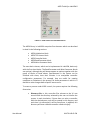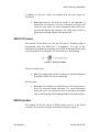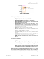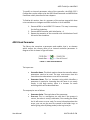
1
Adaptive Predictive Expert Control ADEX Toolkit for LabVIEW 8 User Manual Edition: April 2008 UM‐TK‐LV8‐01‐EN ADEX Toolkit for LabVIEW 8 Contents About this Manual .................................................................................................................. 3 Organization of this Manual ............................................................................................... 3 Conventions........................................................................................................................ 3 Related Documentation ..................................................................................................... 3 About ADEX Toolkit for LabVIEW 8 ........................................................................................ 4 Package Contents ............................................................................................................... 4 System Requirements......................................................................................................... 4 Installing ADEX Toolkit........................................................................................................ 4 ADEX Toolkit for LabVIEW 8 Applications .......................................................................... 5 Part I Integration of ADEX Controllers within National Instruments’ LabVIEW 8 ........................... 6 Introduction........................................................................................................................ 6 ADEX Toolkit Basic Features ............................................................................................... 6 ADEX Blocks ........................................................................................................................ 8 ADEX Initialization .......................................................................................................... 8 ADEX TCP Listener .......................................................................................................... 9 ADEX Controller .............................................................................................................. 9 ADEX Read Parameter .................................................................................................. 11 ADEX Write Parameter ................................................................................................. 12 ADEX Parameter Browser................................................................................................. 12 Part II Control Problem Simulated using the ADEX Toolkit ............................................................ 15 Control Problem Description............................................................................................ 15 Graphics and Simulation in the LabVIEW Environment ................................................... 16 User Manual 2 UM‐TK‐LV8‐01‐EN ADEX Toolkit for LabVIEW 8 About this Manual This manual describes the ADEX Toolkit for National Instruments' LabVIEW 8. The Toolkit includes all the necessary tools for configuring and implementing ADEX controllers within LabVIEW. Organization of this Manual The manual is divided into two main sections: Part I – Integration of ADEX Controllers into National Instruments’ LabVIEW ‐ this chapter describes the ADEX blocks that are part of the Toolkit. Part II ‐ Developing an Example in LabVIEW – it describes the control problem of a real application for maintaining constant the temperature inside a walking beam heat treatment furnace, including the definition of a strategy based on the ADEX Controllers. Conventions This icon denotes a note, which notifies you of important information. This icon denotes a warning, which warns you about information that should not be overlooked for the proper working of the system. Related Documentation The following documents contain information that you might find helpful as you read this manual: ADEX Methodology. ADEX Configurator. User Manual 3 UM‐TK‐LV8‐01‐EN ADEX Toolkit for LabVIEW 8 About ADEX Toolkit for LabVIEW 8 This section will list the contents of the ADEX Toolkit for LabVIEW 8. It describes the installation steps and the applications of the ADEX Toolkit for LabVIEW 8. Package Contents ADEX Toolkit for LabVIEW 8 contains the following: ADEX Toolkit for LabVIEW 8 CD. User manual of the ADEX Toolkit for LabVIEW 8. Hardware Key (USB) that provides the necessary licenses to use ADEX systems. System Requirements To install the ADEX Toolkit for LabVIEW 8, the following are required as a minimum: Windows 2000/XP/Vista. LabVIEW 8.0.1 o later. Installing ADEX Toolkit Complete the following steps to install the Toolkit ADEX for LabVIEW 8: 1. Insert ADEX Toolkit Installation CD. 2. Run setup.exe. 3. Specify the ADEX COP 2 Configurator directory: this must be within the ADEX directory as shown in Figure 1. 4. Then follow the steps to install the drivers for the HASP Hardware key. User Manual 4 UM‐TK‐LV8‐01‐EN ADEX Toolkit for LabVIEW 8 FIGURE 1 – ADEX TOOLKIT SETUP Note: The ADEX Toolkit for LabVIEW will be installed for the latest version of LabVIEW 8 available on the user's computer, inside user.lib folder. After completing the installation, be sure to connect the Hardware key that contains licenses for the implementation of ADEX Systems before using the ADEX Toolkit for LabVIEW 8. ADEX Toolkit for LabVIEW 8 Applications The purpose the Toolkit is to provide a means of simulating ADEX Systems in a familiar, known environment. This is the reason why the Adaptive Predictive Expert methodology has been integrated into LabVIEW, so that it can be used both for carrying out experiments/testing and creating industrial applications. The ADEX Toolkit for LabVIEW 8 contains the necessary tools for developing control applications based on the ADEX methodology in LabVIEW programming environment, both for PC‐based systems and for its implementation in Real‐Time systems. User Manual 5 UM‐TK‐LV8‐01‐EN ADEX Toolkit for LabVIEW 8 Part I Integration of ADEX Controllers within National Instruments’ LabVIEW 8 Introduction ADEX Toolkit for LabVIEW enables ADEX controllers to be added to VIs for simulation and modeling of control systems based on the ADEX methodology. This library is integrated into LabVIEW 8.x as an extra library within the user menu, so it is therefore convenient that the user obtains basic knowledge of this program prior to using the Toolkit. For more information on this environment, please visit the web site of National Instruments at (http://www.ni.com/) In this manual, a full description is given of the toolkit starting from how to install it to outlining features including the blocks which make up the toolkit. The ‘Help’ module, accessible from the toolkit, includes a module allowing the user to access the ADEX parameters necessary for the configuration of the controller. ADEX Toolkit Basic Features Once it is installed, the library can be accessed from the Function Palette of LabVIEW as can be seen in Figure 2: User Manual 6 UM‐TK‐LV8‐01‐EN ADEX Toolkit for LabVIEW 8 FIGURE 2 – ADEX TOOLKIT IN FUNCTIONS PALETTE The ADEX library in LabVIEW comprises five elements which are described in detail in the following sections: ADEX Initialization block. ADEX TCP Listener block. ADEX Controller block. ADEX Read Parameter block. ADEX Write Parameter block. The most basic scheme, which can be implemented in LabVIEW, deals only with the first three blocks. The Read Parameter and Write Parameter blocks are optional, although they will always appear as options together with the group of blocks as listed above. Improvements in the system can be achieved with these, since their function is to manipulate controller configuration parameters. For example, they are useful for treating exceptions or limitations in the process; for those parameters in which it is desired to make changes before specific events occur. To create a process under ADEX control, the system requires the following directories: Directory Ctlrs: In this, controller files relevant to the VI’s are stored inside the directory selected by the user to initialize the system. In each simulation, if there does not exist a controller with the desired name, one will be created in this directory and each time it is referenced, it will be found here. In addition, this directory will have a default controller called ctlrcnf.dfl. User Manual 7 UM‐TK‐LV8‐01‐EN ADEX Toolkit for LabVIEW 8 Directory Logs: Here will be stored a text archive whose purpose is to log information messages or errors generated by the controllers. In any event, it will be the responsibility of the user to ensure that these directories exist; otherwise, if the system does not find them, the ADEX Initialization block will return an error and not work correctly. ADEX Blocks ADEX Initialization This VI is produced by the initialization process of the ADEX system. It must be executed at the start of the first cycle, which means that it is not necessary to initialize the system in all the executions (in the same session of LabVIEW) if there are no changes to the parameters in this block. The terminals can be seen in Figure 3: FIGURE 3 – ADEX INITIALIZATION Here are the following inputs: Controllers Dir Path (Controllers Directory): This pin refers to the directory path Ctlrs mentioned previously. Logs Dir Path (Logs Directory): As is evident from the name, this corresponds to the Logs path. Log Level (Level of register): This will depend on the value applied to this terminal as follows: ¾ 0: Debug mode. ¾ 1: Errors and information (default option). ¾ 2: Error messages only. Max Log Lines (Maximum number of lines): This number indicates the maximum number of log lines, which means that if the limit is exceeded, the first lines of the file will be overwritten. User Manual 8 UM‐TK‐LV8‐01‐EN ADEX Toolkit for LabVIEW 8 In addition to the pins listed, the module also has one output for verification. Error out: Here can be read the results of the operation. 0 means that the process is correct, otherwise this output will return an error code. For more information about the errors, you can see the text file created in the folder Logs, as well as giving value 0 (debug mode) to the Log Level pin. ADEX TCP Listener The function of this block is to set the TCP port to listening mode to communicate with the ADEX COP 2 Configurator. This part of the initialization must be done at the time of the ADEX Initialization Block, once only, during the first VI simulation. The icon of this VI is the following: FIGURE 4 – ADEX TCP LISTENER There is one input only: Port: This contains the number of the port to be initialized which by default is 3030. This has one output pin. And an output: Error out: If the output is not equal to zero, this means that an error has occurred during execution. For more information about the errors, you can see the text file created in the folder Logs, as well as giving value 0 (debug mode) to the Log Level pin. ADEX Controller This module lies at the centre of ADEX systems since it is the actual controller. The icon with its inputs and outputs is shown in Figure 5. User Manual 9 UM‐TK‐LV8‐01‐EN ADEX Toolkit for LabVIEW 8 FIGURE 5 – ADEX CONTROLLER With respect to the input terminals: SP (Set Point): Value of the set point of the PV. PV (Process Variable): Process Output to the controller. PERT (Perturbation): Input available for the introduction of perturbations which affect the PV. AI (Actual Input): The actual value of the latest control action applied to the process. The values sent by the controller and the actual input do not necessarily have to be the same, for various limitations or for other reasons. MODE: The modes of operation of the controller. RC (Rate of Change): This is the maximum rate of change of the PV when it is approaching the set point. CP (Control Period): This is the time interval between control actions. Initialization: In the first cycle in which the VI is executed, this value must be 1 and in the other periods, must equal 0. COM: If the data is received correctly, the user must write a 1 in this pin. The outputs are as follows: OUT: Control action which must be applied to the process. Error out: The result of the operation can be read in this variable. If the process is correct, the variable will be 0 otherwise VI will return an error code. For more information about the errors, you can see the text file created in the folder Logs, as well as giving value 0 (debug mode) to the Log Level pin. Before continuing, it should be noted that the size of SP, PV, OUT, AI, MODE and RC have to be equal to avoid mistakes. Moreover, if we do not want to add perturbations or specify RC or CP, these can be left without connecting. User Manual 10 UM‐TK‐LV8‐01‐EN ADEX Toolkit for LabVIEW 8 To modify an internal parameter value of the controller, the ADEX COP 2 Configurator can be used or else the ADEX Read Parameter and ADEX Write Parameter subVIs, described in later chapters. To finalize this section, here is a summary of the various steps which have to be carried out to integrate an ADEX controller in VI of LabVIEW. 1. Execute ADEX Ini and ADEX TCP Listener. This step is necessary for the first simulation. 2. Execute ADEX Controller with Initialization = 1. 3. Repeat the execution of the controller with Initialization=0 until the end of the simulation. ADEX Read Parameter The library also comprises a parameter read module, that is, an element which returns the current value of an internal controller parameter. A diagram of this is shown in Figure 6 below: FIGURE 6 – ADEX READ PARAMETER The inputs are: Controller Name: This block needs to know the controller whose parameters need to be read. The user must ensure that this controller exists otherwise an error will be returned. Parameter Name: This is a character string which identifies a parameter in particular. Assuming that the name is not overly simple, in the Help section, there is a browser for name searching which will be described later. The output pins are as follows: Parameter Value: The read value of the parameter. Error out: This is a verification pin such that if the process is correct, the value is zero (0) otherwise, if the reading has failed, the VI will return an error code. For more information about the errors, you can see the text file created in the folder Logs, as well as giving value 0 (debug mode) to the Log Level pin. User Manual 11 UM‐TK‐LV8‐01‐EN ADEX Toolkit for LabVIEW 8 ADEX Write Parameter The last element of the ADEX library is shown in Figure 7 and is the parameter writer. Its function is to modify the value of an internal controller parameter. These changes can be carried out during the simulation process, that is, it is not necessary to stop the execution of the program. FIGURE 7 – ADEX WRITE PARAMETER The inputs and outputs of the block are intuitive. In the first group, they are the following: Controller Name: The name of the controller whose parameters require to be changed. First of all, it is necessary to ensure that the controller exists or the module will return an error. Parameter Name: This is a character string which identifies a particular parameter. Parameter Value: The value required to be written. The output pins are: Error out: This is a verification pin such that the value will be 0 if the process is correct otherwise, the VI will return an error code. For more information about the errors, you can see the text file created in the folder Logs, as well as giving value 0 (debug mode) to the Log Level pin. ADEX Parameter Browser Having explained the functioning of the ADEX blocks, it is necessary to know the name of a parameter so that it can be read correctly. Using the name of the parameter in ADEX COP 2 Configurator, the indices and full names can be obtained by means of the ADEX parameters browser (Figure 8). This is referred to in plural since although a particular parameter is being searched, this could have several identifiers and names according to the domain it belongs to and the PV which it affects. User Manual 12 UM‐TK‐LV8‐01‐EN ADEX Toolkit for LabVIEW 8 Moreover, in most cases, the key to be input coincides with the initials of the parameter in English (for example, the Sampling Time is ST). It is possible to access the parameter search engine from the Help section of the Read and Write Parameter modules. The browser opens in a predetermined navigator window in the user’s system (that is in Internet Explorer, Mozilla Firefox or similar) and has the following appearance: FIGURE 8 – ADEX PARAMETER BROWSER To simplify searches, the type of controller to be used can be specified, since the names and indices do not always coincide in the various structures. The types of controller are as follows: 1x1: These are controllers with only one PV and no perturbations. 6x1: These also have only one PV but up to 5 perturbations. 9x3: This is typical of the remainder. In this case there are 3 PV’s and up to 6 perturbations (PERTs). For example, if we want to know the name of the parameter associated with the Prediction Horizon in a 6x1 driver, we should write PH in the textbox and select the appropriate structure, resulting in the following: User Manual 13 UM‐TK‐LV8‐01‐EN ADEX Toolkit for LabVIEW 8 6x1 ADEXCOP 2 Configurator key Index Parameter name Process Var Domain Description PH 26 Pvg1.Ap1.ln PV1 AP-L Prediction horizon PH 61 Pvg1.Ap2.ln PV1 AP-C Prediction horizon PH 96 Pvg1.Ap3.ln PV1 AP-U Prediction horizon FIGURE 9 ‐ SEARCH RESULTS Another feature of the browser is that the inverse also works: if the index is input to the text box, the corresponding parameter will be found. User Manual 14 UM‐TK‐LV8‐01‐EN ADEX Toolkit for LabVIEW 8 Part II Control Problem Simulated using the ADEX Toolkit The purpose of this section is to illustrate the functions of the toolkit in LabVIEW using an example. The objective is not to be a guide for configuring adaptive predictive expert controllers (although there are many references here), but rather, to familiarize the user with the toolkit. You can access this demonstration through the LabVIEW application NI Example Finder (Industry Applications / Process Control). Control Problem Description It is required to control the temperature inside a walking beam (steel) heat treatment furnace by means of a master control action on the air‐fuel ratio. The automatic control objective is to maintain the inside temperature at the set‐point while avoiding exceeding this value at all times. Due mainly to the insertion, removal and shifting of the beams around the interior of the furnace, the temperature inside the furnace is not uniform. Two temperature sensors (thermocouples) have been installed at different points, and the aim is to control whichever of the two temperatures is higher. Figure 10 illustrates the process to be controlled: Temperature inside the furnace at point 1 Temperature inside the furnace at point 2 Master control action on the air fuel ratio FIGURE 10 ‐ WALKING BEAM (STEEL) HEAT TREAMENT FURNACE User Manual 15 UM‐TK‐LV8‐01‐EN ADEX Toolkit for LabVIEW 8 The strategy consists of having two ADEX controllers, each one operating on one of the temperature readings (PV1 and PV2). Both controllers receive the temperature set‐point (SP), the actual control action (AI) and the mode (MODE) of operation (manual or automatic) as common input signals. The control action to be applied is that of the controller which is receiving the greater of the two temperatures. The simultaneous operation of both ADEX controllers offers the advantage that the controller which is not sending the control signal keeps the adaptation mechanism functioning and thus, when it comes back into operation, it still “knows” the process. Graphics and Simulation in the LabVIEW Environment To begin with, to create the strategy diagram in LabVIEW it is necessary to create the folders Ctlrs and Logs mentioned in previous sections. By way of a reminder, the steps which this VI example needs to take are as follows: 1. Execute ADEX Initialization and ADEX TCP Listener. This step is only necessary for the first simulation. 2. Execute the ADEX Controller with Initialization = 1. 3. Repeat the execution of the controller with Initialization = 0 until the end of the simulation. To start with, a Stacked Sequence structure has to be positioned as shown in Figure 11, with the aim of separating the first initialization step (1 & 2) (which is only required for the first simulation) from the rest of the diagram (3). FIGURE 11 ‐ STACKED SEQUENCE For steps 1 & 2, in the first frame, the following scheme is implemented: User Manual 16 UM‐TK‐LV8‐01‐EN ADEX Toolkit for LabVIEW 8 FIGURE 12 ‐ INITIALIZATION PHASE In this way, the folders Ctlrs and Logs in the working directory can be found and the listening TCP port is initialized at 3030. The Boolean ini, with its respective case is s flag to indicate if this phase has been carried out or not. Later, in another frame, stage 3 (Figure 13) will be included. In addition, by means of the inclusion of a while structure, these processes will form a simulation cycle. FIGURE 13 – SIMULATION LOOP User Manual 17 UM‐TK‐LV8‐01‐EN ADEX Toolkit for LabVIEW 8 As can be seen from the diagram above, the while loop is divided into two frames which are executed sequentially: on one side is the control strategy and on the other, the furnace and temperature sensors have been modeled. Considering first the control strategy, two ADEX controllers have been used named TC1 and TC2. Given the ability of the subVIs to manipulate arrays, other VIs of LabVIEW have been used to ‘convert’ the signals implicit in these structures and vice versa. Once the control actions have been generated, the signal with the highest PV value is selected and this ensures that the set point will not be exceeded. Before a simulation, it is necessary to configure the default value of ini?, setting it to TRUE. In this way, as the test starts, it executes the initialization functions ADEX Ini and ADEX TCP Listener (Figure 12). As can be seen in Figure 13, the first action on the controllers is with ini? = TRUE (Initialization = 1) and immediately afterwards, the value changes to FALSE (or in other words Initialization = 0). On returning to execute the controllers, ini? will not have changed state so that until the end of the simulation, the value of Initialization will be maintained equal to 0. In addition, if the boolean AUTO is set to FALSE, the OUT signal will have the last value. Another point to be considered is the furnace model and the sensors, indicated in the right hand part of Figure 13. Two “Formula Node” for each PV, one to represent the model equation and the other located beforehand to generate changes in the coefficient B1 of the process. Continuing with the VI example, once the parameters have been adjusted for each controller, the results in the graphics of the Front Panel (Figures 14 & 15) can be observed: User Manual 18 UM‐TK‐LV8‐01‐EN ADEX Toolkit for LabVIEW 8 FIGURE 14 ‐ RESULTS OF TEMPERATURE CONTROL OF THE FURNACE FIGURE 15 ‐ RESULTS OF TEMPERATURE CONTROL OF THE FURNACE These results demonstrate the accuracy achieved with the control strategy designed using ADEX controllers. In Figure 15 you can be note clearly the manner in which the goal is met, and that, despite the fluctuations in temperature, the global temperature does not exceed the set point in more than 0.5 ° C. User Manual 19 UM‐TK‐LV8‐01‐EN ADEX Toolkit for LabVIEW 8 This problem demonstrates the versatility of control schemes and additional options that can be achieved by means of using ADEX Toolkit. This allows the user to integrate in LabVIEW automatic control strategies, designed for a specific process control. User Manual 20 UM‐TK‐LV8‐01‐EN