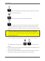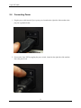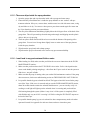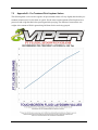
1
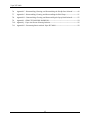
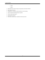
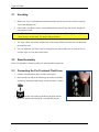
User Manual Viper XPT 6000 Revision 1.14.11.1 – January 14th, 2011 1-1 Viper XPT-6000 1-2 Viper XPT-6000 Contents 1.0 SYSTEM OVERVIEW ..................................................................................................... 1 1.1 System Overview ....................................................................................................................................................... 2 2.0 GETTING STARTED ....................................................................................................... 5 2.1 Uncrating ...................................................................................................................................................................... 6 2.2 Stand Assembly .......................................................................................................................................................... 6 2.3 Connecting the Pre-Treatment Fluid Lines .................................................................................................... 6 2.3.1 Selecting Fluids for Spraying ........................................................................................................................... 8 2.4 Connecting Power ................................................................................................................................................... 11 2.5 Preparing Viper for Pre-Treatment ................................................................................................................. 12 3.0 USING THE TOUCH SCREEN INTERFACE ...................................................................... 13 3.1 Control Screen .......................................................................................................................................................... 14 3.1.1 Fluid Laydown............................................................................................................................................................... 14 3.1.2 Spray Length.................................................................................................................................................................. 14 3.1.3 Spray Zones .................................................................................................................................................................... 15 3.1.4 Job Counter ..................................................................................................................................................................... 15 3.2 Zones Screen ............................................................................................................................................................. 16 3.3 Counter Screen ......................................................................................................................................................... 16 3.3.1 Job Counter ..................................................................................................................................................................... 17 3.3.2 Total Sprayed ................................................................................................................................................................ 17 3.4 Menu Screen .............................................................................................................................................................. 17 3.4.1 Fluid Maintenance ...................................................................................................................................................... 18 3.4.2 Move Platen .................................................................................................................................................................... 18 3.4.3 General Settings ........................................................................................................................................................... 18 3.4.4 Language ......................................................................................................................................................................... 19 3.3.5 Customize Buttons ...................................................................................................................................................... 20 4.0 Spraying a Garment ................................................................................................... 21 4.1 Loading a Garment ................................................................................................................................................. 22 4.2 Setting Spray Parameters .................................................................................................................................... 22 4.2.1 Setting the PT FLUID SPRAY value: .................................................................................................................... 22 4.2.2 Setting the SPRAY LENGTH value: ...................................................................................................................... 22 4.2.3 Setting the SPRAY ZONES:....................................................................................................................................... 22 1-3 Viper XPT-6000 4.2.4 Fluid Laydown............................................................................................................................................................... 22 4.3 Starting Spray ........................................................................................................................................................... 23 4.4 Unloading and Curing/Drying Garment ........................................................................................................ 23 4.5 Pre-Treament Fluid Laydown Values ............................................................................................................. 23 5.0 MAINTENANCE .......................................................................................................... 25 5.1 Keeping the Viper Clean ....................................................................................................................................... 26 5.2 Daily Preventative Maintenance ....................................................................................................................... 26 5.2.1 - Nozzle/Spray Tip Maintenance ............................................................................................................................. 26 5.2.2 - Cleaning the Viper Nozzle Tips : ............................................................................................................................ 27 5.2.3 - To Clean the Yellow Spray Suppressant Guards : ......................................................................................... 28 5.3.4 5.3 Machine Body Maintenance ................................................................................................................................... 28 Weekly Preventative maintenance ............................................................................ 29 5.3.1 Nozzle/Spray Tip Maintenance ............................................................................................................................ 29 5.3.2 Machine Body Maintenance ................................................................................................................................... 31 5.3.3 Internal Maintenance ................................................................................................................................................ 32 5.3.4 Flushing the Fluid System with Anti-Venom ................................................................................................... 33 6.0 6 Troubleshooting ........................................................................................................ 35 Troubleshooting ........................................................................................................................................................... 36 6.1 General Troubleshooting ..................................................................................................................................... 36 6.1.1 - The Viper will not turn on/doesn’t have any power: ................................................................................... 36 6.1.2 - The Viper will not spray pre-treatment fluid: ................................................................................................. 36 6.1.3 - The Spray Pattern is “blotchy”................................................................................................................................ 36 6.1.4 - The Spray Pattern has gaps or appears to not be irregular: ................................................................... 37 6.1.5 - There are drips inside the spray chamber: ....................................................................................................... 38 6.1.6 - I can’t load in any pre-treatment fluid or water:........................................................................................... 38 6.1.7 - Certain Spray Heads will not spray fluid: .......................................................................................................... 39 6.1.8 - The moving platen shudders, grinds or binds when trying to move in or out or spraying: ....... 39 7.0 7 Appendix .................................................................................................................. 41 Appendix.......................................................................................................................................................................... 42 7.1 Appendix A – Stand Assembly ................................................................................................................................ 42 7.2 Appendix B – Pre-Treatment Fluid Laydown Values .................................................................................. 43 7.3 Appendix C – Valve and Fluid Connection Information ............................................................................. 44 7.4 Appendix D – Viper Anti-Venom Cleaning Solution: ................................................................................... 45 7.5 Appendix E – Disassembling, Cleaning, and Reassembling the Brass Pressure Relief Valve .... 47 1-4 Viper XPT-6000 7.6 Appendix F – Disassembling, Cleaning, and Reassembling the Exit By-Pass Solenoid ................ 49 7.7 Appendix G – Disassembling, Cleaning, and Reassembling the Fluid Pump .................................... 51 7.8 Appendix H – Disassembling, Cleaning, and Reassembling the Spray Head Solenoid................. 52 7.9 Appendix I – SPRAY TIP CLOGGING AND WEAR ........................................................................................... 54 7.10 Appendix J – Viper Anti-Venom Cleaning Solution: ..................................................................................... 56 7.11 Appendix K – Pretreating Basics with the Viper XPT-6000 ..................................................................... 58 1-5 Viper XPT-6000 1-6 1.0 SYSTEM OVERVIEW 1 Viper XPT-6000 1.1 System Overview WARNING!!! The Viper XPT is designed for applying pre-treatment fluid to apparel that will be used for white ink direct-to-garment printing. User assumes all risks associated with the use of the machine and the fluids run through the Viper XPT. WARNING!!! Disconnect Viper from power source before any servicing of the machine to reduce potential for shock. Viper XPT Specifications Dimensions: INSERT DIMENSIONS HERE Weight: Viper 220 lbs / 40lbs stand 110VAC (230VAC European model) 1.5 amps Diaphragm pump with over pressure relief valve set to 60 psi Other Information regarding the Viper: 2 Viper XPT-6000 LABELS: Keep all bodily parts and items away from and out of these areas. Shock Hazard – 110V input point. This is to warn that the unit needs to be disconnected from the power source before servicing or cleaning the machine. Fuse Holder CAUTION – Warning for replacing the fuse with the correct sized fuse (2 amp GMA type) and also to remind the user to disconnect the machine from the power source prior to changing the fuse. The Viper XPT-6000 is an industrial system to apply a pre-treatment solution to garments that are to be printed on a digital inkjet garment printer. Features include: Touch screen interface Control of spray length and fluid laydown Zone Spraying – save pretreatment by selecting zone / shirt size to be treated: o Full Adult o Left Chest o Right Chest o Youth o Infant o Independent Spray Head Control by the User Interchangeable Platens o Adult 3 Viper XPT-6000 o Youth o Infant Minimal bounce and overspray of sprayed pre-treatment solution Multi-lingual interface Plug & Play – just power up the machine to start treating Easy to load and unload garment on platen Easy weekly maintenance Job and total counters Ideal and consistent pre-treatment solution lay-down 4 2.0 Getting Started 2.0 GETTING STARTED 5 Viper XPT-6000 2.1 Uncrating 1. Remove the Viper’s included metal stand and assemble (See Section 2 below) before removing Viper from shipping crate. 2. Once stand is assembled, remove excess cardboard from around Viper and lift unit straight off crate and onto stand. CAUTION: The unit is heavy and requires at least two people to lift the Viper from the box when placing it on the stand. Use proper lifting techniques. 3. The Viper’s back will sit flush with the back of the stand, and the feet on the base will drop onto the stand foot rests. 4. You can adjust the feet of the Viper by rotating the feet pads to either raise or lower the feet to level the Viper as it sits on the metal stand. 2.2 Stand Assembly Please see Appendix A, Stand Assembly, for stand assembly instructions. 2.3 Connecting the Pre-Treatment Fluid Lines 1. Find the 4 included tubes and 2 red filters and unpack. 2. Insert one tube in each of the following ports on the back of the machine by inserting the tube firmly into the connector. (Figure 2.3B) 3. One tube will connect to the Water IN quick connect. Make sure that the tube labeled IN is inserted into this port. Fig. 2.3 B – Firmly insert tube. Figure 2.3-B 6 Viper XPT-6000 4. Another tube will connect to the Pre-Treatment 1 IN quick connect. Make sure that the tube labeled IN is inserted into this port. 5. The third tube will connect to the Water Out/Waste quick connect. 6. The fourth tube will connect to the Pre-Treatment 1 OUT quick connect. The fluid out tube for the pre-treatment has a red check valve on one end. This end has a shorter hose tube connected to the check valve. The SHORT end of the hose is what is placed into the pre-treatment container. CAUTION: REVERSING THIS FLUID OUT HOSE CAN RESULT IN A PRESSURE BUILD UP THAT CAN BLOW THE CHECK VALVE OFF THE TUBE CONNECTION POINT OR A TUBE CAN BURST IN THE SPRAY CABINET. USE EXTREME CAUTION WHEN HOOKING THIS UP. 7. Take the two supplied white rigid plastic tubes and thread the Water In and Pre-treatment 1 In tubes through the white rigid plastic pipe. (The and ports on the back of the machine) 8. Connect a red filter to each of the two tubes you just put through the white rigid plastic pipe. (the Water In and Pre-treatment 1 In ports). 9. Place the pre-treatment IN and OUT tubes in your pre-treatment solution containers. Place the water IN tube in a container with water, and the water OUT in a waste container*. 7 Viper XPT-6000 WARNING: It is highly recommended that you use distilled water for cleaning out routines and Viper Anti-Venom for general maintenance in the Viper. Failure to do so violates the warranty. NOTE: * Pre-treatment, water and waste containers are not included. Use the pretreatment solution container, your own containers or order Viper branded containers, available online from ViperXPT.com. Additional tubes for connecting a second pretreatment are also available. ** See Appendix 7.3 for detailed information on the Valve and Fluid Ports. 2.3.1 Selecting Fluids for Spraying During the normal course of use you will need to select different fluids for different purposes. You can select water for use in cleaning the Viper and flushing the fluid lines to keep your machine operating in top condition. 8 Viper XPT-6000 Here’s a quick guide to the Valves and how to use them. The valve selector on the top allows you to select which fluid you would like to allow the Viper to use or pull into the delivery system. There are 4 options for this valve: Water In (used for cleaning the Viper) Pre-Treatment Fluid 1 Pre-Treatment Fluid 2 None (allows air into the system to flush all fluids out of the fluid delivery system in the Viper). The valve selector on the bottom is the return fluid (fluid out of the Viper) selector. This valve setting will allow the fluid that is not used in the system to be returned to an external container. There are 3 options for the bottom valve: Waste Water Return Pre-Treatment Fluid 1 Return Pre-Treatment Fluid 2 Return Normally you will position the top and bottom valve selectors to the same input/output selection choice. To Select a Fluid: 1. Turn the top selector to the fluid of your choice. 2. Turn the bottom selector to the fluid of your choice. 9 Viper XPT-6000 WARNING! Do not turn the bottom valve selector to the 12 o’clock position. This is not a valid option and will result in the possibility of the Viper fluid delivery system over pressurizing and resulting in a tube failure. This will create a wet mess in your machine you will have to clean up. Only position the bottom valve in the 9 o’clock position(Waste water return), 6 o’clock position (Pre-Treatment 1 return) or the 3 o’clock position (Pre-Treatment 2 return). 10 Viper XPT-6000 2.4 Connecting Power 1. Plug the power cable into the Viper’s power port, located on the right side of the machine, then plug into a grounded outlet. 2. Power on the Viper XPT by toggling the power switch, located on the right side of the machine above the power cord. 11 Viper XPT-6000 2.5 Preparing Viper for Pre-Treatment 1. Eject the platen 2. On the touch screen, select the Menu tab at the top. a. Select Platen In/Out option. b. The platen will move in or out depending on the direction that it last traveled. If the platen moves in, select the Platen In/Out button to move the platen back out. 3. Place the included yellow Sham-moo cloth on the platen once it is ejected 4. Select the Fluid Maintenance button on the menu screen, then select the Fill button 5. Follow the On-Screen instructions to complete the line fill. 12 Viper XPT-6000 3.0 USING THE TOUCH SCREEN INTERFACE 13 Viper XPT-6000 3.1 Control Screen The control screen is the main screen of the Viper’s touch screen interface will load when the Viper is powered on. This screen allows for change the fluid laydown, the length of the spray, and zone of the shirt that pre-treatment will be applied to. You can also Navigate to any of the menus by pressing the tabs at the top of the screen. Figure 3.1 3.1.1 Fluid Laydown The fluid laydown option changes the amount of liquid that is sprayed. To change fluid laydown, you can press the numerical display which will allow you to manually enter a fluid laydown value or you can press one of the preset “buttons”. (*updated 12/3/09) If you press the numerical number display, enter a fluid laydown value between 17 and 100 (17 being less, 100 being more). Press enter to activate the value and close the popup. Figure 4.1 Fluid laydown values control the amount of fluid that is sprayed. For more information on choosing the laydown value that is appropriate for your application, please see section 4.2.1, Choosing Fluid Amounts. 3.1.2 Spray Length Figure 3.1.1 The spray length determines the length down the platen that fluid is sprayed. To change the spray length, press the numerical value. On the popup input screen, enter the desired spray length in inches. Press enter to activate the value and close the popup. 14 Viper XPT-6000 You can also press the + or – increment buttons to increase or decrease the spray length values. 3.1.3 Spray Zones The Viper is designed with 6 independently controllable spray heads. This allows you to save money in pre-treating by reducing the amount of fluid laid down on the garment by “zoning” your spray pattern. The Viper has several built-in preset spray configurations. These configurations are changed simply by pressing on the image of the Shirt on the main display screen. Each tap of the shirt will change to the next available preset value and the spray length indicator on the shirt will also change to visually indicate the new spray pattern. These spray patterns are as follows: ● Full Adult ● Left Chest ● Right Chest ● Youth ● Infant ● Independent Spray Head Control by the User You can also independently control each spray head by clicking on the Custom Spray Zone button to the right of the T-Shirt icon to manually select each head to create your own spray patterns. See section 3.2 for more information on this feature. 3.1.4 Job Counter The job counter shows how many spray cycles have been completed for the current job. This value can be reset from the Counter screen. See section 4.3 for more information. 15 Viper XPT-6000 3.2 Zones Screen The Zones screen (or tab) allows you to manually select and turn on specific spray heads on the Viper to allow you to create a customized spray pattern. The heads are numbered 1 through 6 from left to right and correlate to the spray heads as you stand in front of the Viper. Simply press the corresponding round Figure 3.2 circle below the indicated head to turn it on, press it again to turn it off. After you have selected the heads you want to turn on and spray, press the RETURN button. This will return you to the Main User Screen and display a CUSTOM SPRAY PATTERN text in the t-shirt icon to indicate you are in a custom spray pattern. 3.3 Counter Screen The Counter Screen shows you the total number of garments sprayed since you have turned the machine Figure 4.1 on as well as the total sprayed on the unit. You can only reset the JOB COUNTER counter by pressing the RESET JOB COUNTER button. 16 Viper XPT-6000 3.3.1 Job Counter The JOB COUNTER shows the total number of shirts sprayed since you turned the Viper on or since you last pressed the RESET JOB COUNTER button. 3.3.2 Total Sprayed Figure 3.4 – Counter Screen The total sprayed counter shows the total number of sprays that have been completed on the Viper XPT-6000. This counter can not be reset Figure 4.5 – The MENU tab/screen 3.4 Menu Screen The MENU tab screen contains several buttons that allow you to do general maintenance on the Viper as well as changing the general settings on the touch screen, selecting the language to be displayed on the touch screen as well as changing and setting the user modifiable PT Fluid laydown buttons. 17 Viper XPT-6000 3.4.1 Fluid Maintenance The Fluid Maintenance button will provide you with several options to load, clean, empty and change fluids within the Viper XPT. Specific fluid maintenance routines are explained the Maintenance section of this manual. 3.4.2 Move Platen By pressing the MOVE PLATEN IN/OUT button will cause the platen on the Viper to move either in or out. If the platen is in the complete OUT position and you press the MOVE PLATEN IN/OUT button the platen will be moved so that it is completely in the back of the unit. This is the preferred position for storage when power is turned off to the Viper. If the Platen is somewhere in between the full out position and the full in position, the platen will return to the home starting point when the MOVE PLATEN IN/OUT button is pressed. 3.4.3 General Settings The GENERAL SETTINGS button allows you to set the following items on your Viper control screen: A MACHINE STATUS CODE is also displayed on the GENERAL SETTINGS screen. This is only used when trying to diagnose a problem with the Viper and when a certified Viper technician asks for it. Figure 4.7 – The GENERAL SETTINGS options 18 Viper XPT-6000 3.4.3.1 - Setting the Brightness/Contrast When you press the SET BRIGHTNESS/ CONTRAST button you will be able to manually set the brighness and contrast of the touchscreen. Simply use your finger to drag the lever for each option to increase or decrease the values to allow you to easily view the touchscreen in under your Figure 4.7 – The BRIGHTNESS/CONTRAST shop’s conditions. options settings. 3.4.3.2 - Setting the Date/Time When you press the SET DATE/TIME button you will be able to set the touch screen’s date and time that is displayed on the main screen. Figure 4.7 – The DATE/TIME 3.4.4 Language options settings By pressing the LANGUAGE button you will be able either select: English Spanish French German . Figure 3.4.4 – LANGUAGE button allows you to select either English, Spanish, French or German. 19 Viper XPT-6000 3.3.5 Customize Buttons The CUSTOMIZE LABELS screen allows you to manually set the button labels found on the main User Interface screen. These values are associated with the “preset buttons” for the PT Fluid Laydown on the main user screen. The text for the buttons can contain up to 8 characters maximum. The values associated with those buttons can be preset to a value between 16 and 40. The higher the value the more fluid is applied to the garment when the machine is operated. Simply select the button on the right side of each label or value Figure 4.5 – The CHANGE BUTTONS option amount to bring up a data entry box where you can allows you to customize the PT Fluid spray button type in the values you want for the selected item. values and display text. 20 Viper XPT-6000 4.0 SPRAYING A GARMENT 21 Viper XPT-6000 4.1 Loading a Garment There are two methods for loading a garment onto the Viper platen. 1. The shirt can be loaded onto the platen in a manner similar to loading a screen printing press. Simply hold the shirt open so that one side of the shirt to be sprayed lays on top of the platen and non-sprayed side lays on the platen support tray. This is the preferred method since you can more easily smooth out the shirt to get rid of wrinkles. 2. The shirt can also just lay flat on top of the platen. This method can be used to load smaller shirts that will not fit onto the adult platen, however it is more prone to misplacement and wrinkles. 4.2 Setting Spray Parameters 4.2.1 Setting the PT FLUID SPRAY value: Before using the Viper each time you must set the PT FLUID LAYDOWN value by selecting it from one of the preset buttons or by manually entering a PT FLUID LAYDOWN value in the in numerical display. The higher the number, the more fluid is applied to the garment. A value of 17 will lay down a minimal amount of fluid. A value of 50 will lay down the maximum amount allowed by the Viper. 4.2.2 Setting the SPRAY LENGTH value: You will need to set the spray length value of the area to be pre-treated. Simply set a value of between 1” and 19” in length. This should correspond to the image size you are printing. Just remember to allow for about an 1” – 1.5” on the top and bottom for clearance when loading the pre-treated shirt onto your direct to garment printer. This will give you some “wiggle room” in case you don’t position the shirt correctly on the garment printer. 4.2.3 Setting the SPRAY ZONES: You will also want to set the spray zone that is applicable for your design being printed. If you are doing a left chest, you would only want to spray the left side of the shirt – not the whole width of the shirt. 4.2.4 Fluid Laydown Where applicable, for each sub-function referenced within a section in 4.x, describe in detail and depict graphically the sub-function name(s) referenced. Include screen captures and descriptive narrative. 22 Viper XPT-6000 4.3 Starting Spray To apply the pre-treatment to the shirt, make sure that the shirt is loaded correctly and all the settings are appropriate, press the green START button. The Viper will pull the platen into the Viper and spray the shirt. NOTE: If there is an issue where you need to stop the machine immediately for any reason, press the red EMERGENCY STOP button at any time. This will stop all motion of the Viper as well as turn all pumps and solenoids to the off position. 4.4 Unloading and Curing/Drying Garment Any shirt that has been pre-treated will need to be removed from the Viper and cured or “dried”. The most common method of curing the pre-treatment is by using a heat press. Check with your manufacturer’s pre-treatment instructions for the curing / drying of the pre-treatment. 4.5 Pre-Treament Fluid Laydown Values The chart in figure 4.5 is a sample representation of the amount of fluid laid down by the Viper XPT. Though all pre-treatment fluid is going to weigh slightly differently, the chart will get you within general guidelines. You must refer to the manufacturer’s pre-treatment guidelines for the proper amount of pretreatment to be applied to the garments. This may vary from manufacturer to manufacturer for lights and darks or other types of pre-treatment solutions. 23 Viper XPT-6000 The most accurate way to measure the amount of fluid that the Viper is spraying for your particular pretreatment fluid is to use a gram scale. First weight the un-treated shirt and zero or tare out the gram scale. Then pre-treat the shirt for the manufacturer’s recommended pre-treatment area and then re-weigh the shirt. The resulting grams of PT fluid is how much the Viper sprayed for that particular PT FLUID SETTING value. Figure 4.5 – The above chart is a general representation of the amount of fluid laid down on the garment. 24 5.0 Maintenance 5.0 MAINTENANCE 25 5.1 Keeping the Viper Clean WARNING! Disconnect the Viper XPT from the power source by unplugging the power inlet cord from the machine before doing any maintenance work or cleaning. After use of the Viper, pre-treatment bounce will start to accumulate on the plastic deck and housing. It is recommended that after each use that a damp rag or sponge is used and wipe down the plastic decking, stainless steel shirt support tray, and interior to keep the pre-treatment from accumulating. This will reduce further maintenance and keep your machine running more smoothly. You can also open the garage door of the unit to wipe down the insides of the spray chamber. A clean Viper will give you many years of dependable service! WARNING! To open the front “garage door” or the Viper use both hands and lift the garage door from the middle of the door opening. 5.2 Daily Preventative Maintenance 5.2.1 - Nozzle/Spray Tip Maintenance To keep the Viper’s fluid systems and spray tips functioning correctly, run the Viper’s Clean routine once per day. 26 Items needed: 1 L Distilled water Waste bucket or container 1. Run the “Water In” hose to the distilled water. Run the “Water Out” hose to a waste bucket or container. 2. Power on the Viper and select the Menu Screen (or press the F4 button). 3. From the Menu Screen, click the Fluid Maintenance button. 4. From the Fluid Maintenance screen, select the Clean button. 5. Follow all on-screen instructions 6. Discard wastewater after clean routine is complete You also need to remove the absorbent Yellow Spray Suppressant Guards that lines the inside of the front garage door and behind the spray bar. These yellow Spray Suppressant Guards collect over spray to help keep your Viper cleaner and hold onto excess spray bounce. These are held in with Velcro. 5.2.2 - Cleaning the Viper Nozzle Tips : After flushing the system with distilled water you will want to use a very soft bristle toothbrush and clean the nozzle tips using Viper Anti-Venom cleaning solution. CLEANING THE NOZZLE TIPS IS NECESSARY TO PREVENT ANY PRE-TREATMENT SOLUTION FROM REMAINING ON THE NOZZLE TIPS AND DRYING OUT CAUSING SPRAY PATTERN PROBLEMS. FAILURE TO DO THIS WILL RESULT IN NOZZLE TIPS THAT MAY NOT BE ABLE TO BE CLEANED TO RETURN THE VIPER TO ITS ORIGINAL SPRAY PATTERN. THE USER WILL THEN NEED TO PURCHASE A NEW TIP TO REPLACE NOZZLE TIPS THAT ARE THE RESULT OF DRIED PRE-TREATMENT OR PRE-TREATMENT BUILDUP ON THE TIPS. 1. Take a toothbrush and some Viper Anti-Venom. 2. Starting with Nozzle Tip 1 clean the tip with the wet tooth brush. Make sure to clean the entire tip thoroughly. 3. After cleaning Nozzle Tip 1, rinse the tooth brush off and re-wet. 27 4. Repeat Steps 2 and 3 until all the nozzle tips have been cleaned. 5. Soak the tips in a small container of Viper Anti-Venom so that the tips are completely submerged. ** NOTE: Sometimes stubborn dried deposits on the tips will cause distortions of the spray pattern. Soaking the tips in the Viper Anti-Venom over night and then repeating steps 1-4 above can help remove the deposits and restore clean spray patterns. Thoroughly rinse the tips off with distilled water to remove any residue of the Anti-Venom. 5.2.3 - To Clean the Yellow Spray Suppressant Guards : 1. Remove the guards (fabric) from the inside of the garage door and from behind the spray heads from the Velcro attachment points. 2. Rinse under warm water and squeeze to remove pre-treatment build up. 3. Repeat rinsing until no more pre-treatment is remaining in the suppression guards. 4. Wring dry. 5. You can heat press the suppression guards flat and to dry them out. Doing this will result in a smooth, flat suppression guard to allow for easier installation back into the Viper. 6. Replace the suppression guards centering them on the provided Velcro strips. a. Make sure the suppression fabric behind the spray bars hangs below the elbow (rear point where the hinge connects) so that it hangs down below that elbow point by about ½”. b. Insert the front suppression guard – centering it on the Velcro strip. You can leave this hang down slightly below the front edge of the throat /opening of the garage door. At least keep the guard even with the bottom of the front opening on the door to keep buildup of fluid from happening and resulting in potential drips of fluid on to your garments. 5.3.4 Machine Body Maintenance To prevent pre-treatment buildup on the Viper, clean the machine’s body at a minimum of once per day. If the unit is being used heavily and any pre-treatment fluid is building up on the deck or other body components make sure to wipe these areas down before they get a chance to leak or drain into the mechanical areas of the Viper. Items needed: Viper Anti-Venom Spray-n-Wipe 28 1. Lift the “garage door” hood of the Viper. 2. Using the Viper Anti-Venom Spray-n-Wipe, thoroughly clean all accessible surfaces of the machine. Make sure to clean up any pre-treatment residue. 3. With the platen in the full out position you can remove the platen and reach back into the Viper to clean the plastic in those areas. This will prevent buildup of residue inside the machine keeping the machine running smoother. 5.3 WEEKLY PREVENTATIVE MAINTENANCE 5.3.1 Nozzle/Spray Tip Maintenance If you have a persistent problem with a spray tip nozzle pattern you may need to remove the tip to try to clean it more thoroughly or to remove any contaminants that might be clogging the tip. Items needed: Toothbrush, distilled water, Viper Anti-Venom 1. Remove nozzle from spray head one at a time by loosening black nut. Be careful when removing the spray tip as there is black o-ring that seals the tip to the spray head solenoid. Sometimes the oring will come off with the spray tip. Other times it will remain in the spray solenoid. Be very careful to NOT LOSE THIS O-RING OR THE HEAD WILL LEAK WHEN APPLYING PRETREAMTMENT. Figure 5.3.1 – Removing the spray tip nut. Be careful the o-ring doesn’t come out along with the nozzle tip. 29 2. Gently scrub nozzle with toothbrush and water until clean. Be sure to thoroughly clean spray orifice. You can use a mild cleaner or even Windex to clean the tip. The tip should be free from any buildup or pre-treatment residue. NOTE: For tips that have stubborn build up on the tips or in the tips running the nozzle tips through your dishwasher might help. Make sure to use high temp water setting if available on your dishwasher. This might help break up other deposits on your tips that the toothbrush might not be able to remove otherwise. Additional replacement tips are available by calling i-Group Technologies. Figure 5.3.2 – Scrub the spray tips with Viper AntiVenom, then rinse with warm soapy water and a tooth brush. 3. Replace spray tip and black nut. When tightening the tip back into place make sure that it is at a slight angle to the other tips. This angle should be about a 5 degree angle – refer to one of the other tips for reference. 30 Figure 5.3.3 – Replace the tip and black nut that holds the tip in place.. 4. Repeat with other nozzles. 5.3.2 Machine Body Maintenance To prevent pre-treatment buildup on the Viper, clean the machine’s body at a minimum of once per day. If the unit is being used heavily and any pre-treatment fluid is building up on the deck or other body components make sure to wipe these areas down before they get a chance to leak or drain into the mechanical areas of the Viper. Items needed: Viper Anti-Venom Spray-n-Wipe 4. Lift the “garage door” hood of the Viper. 5. Using the Viper Anti-Venom Spray-n-Wipe, thoroughly clean all accessible surfaces of the machine. Make sure to clean up any pre-treatment residue. 6. With the platen in the full out position you can remove the platen and reach back into the Viper to clean the plastic in those areas. This will prevent buildup of residue inside the machine keeping the machine running smoother. 31 5.3.3 Internal Maintenance You may find it necessary to access the transport system of the Viper. If this is necessary you will need to remove the Viper Hood and Garage Door. To Remove the Hood and Garage Door 1. Open the Garage door. 2. If this is the first time you are accessing the transport system you will need to remove a plastic nut that connects the Hood to the Electronics Control Panel 3. To remove this nut, take a flat headed screw driver and place it between the hood and the electronic control panel as indicated in the picture below. 4. Remove all six screws that hold the Hood to the Deck. 5. HAVE SOMEONE HELP YOU REMOVE THE HOOLD AND GARAGE DOOR BY LIFTING BOTH VERTICALLY FROM THE DECK AS INDICATED IN THE PICTURE BELOW. 6. Place the Hood and Garage Door assembly on a flat surface that is out of your way. To Access the Transport System Once the Hood and Garage Door are removed you will see the Access Panel on the Viper deck. To gain entry into this Access area, remove all 10 screws from this panel. Some units may not have screws holding in the access panel which may just be removed by hand. Removing the Bellows To access the transport system for cleaning you will need to remove the bellows. 1. The bellows are held in position with Velcro. 2. To remove the front bellow, carefully lift the tabs from the connection points on the shoe. Once that is free, you can carefully separate the Velcro from the bellows where they attach on the front of the machine. Remove the rear bellow in the same fashion. 3. Once removed, the bellows can be rinsed under warm water to rinse off the pretreatment buildup. 32 Cleaning the Rail System A clean, lint free , damp cloth can be used to wipe down the rail system completely removing any residue of pretreatment. Ensure that the rails are cleaned completely even in the crevices. Also, clean the rail guides that the bellows rest upon. Completely clean any residue of pretreatment from these rails. Re-Assemble the Viper Re-assemble the machine in the reverse order that it was disassembled. 5.3.4 Flushing the Fluid System with Anti-Venom The Viper Anti-Venom Cleaning Solution is designed to be recirculated through your Viper XPT-6000 via the H2O Fluid IN and OUT ports. It is highly suggested that you utilize a 1 liter container like the Viper Anti-Venom 1 Liter sized container as your re-circulation fluid holder. How to Use the Viper Anti-Venom 1. Empty the Viper of pretreatment by running a Fluid Empty routine per on screen 2. 3. 4. 5. 6. 7. instructions. Place the water IN and OUT fluid lines into the 1 liter container of Viper Anti-Venom Cleaning Solution. Run a Fluid FILL routine as per the Viper instructions. To fully clean and maintain the Viper, run 3-5 cycles of the fluid FILL routine as per Step 3 above. Empty the Viper of Anti-Venom Cleaning Solution by running a Fluid Empty routine. Place the water IN line back into a clean container of distilled water. Place the water OUT line back into your waste water container. 8. Run two Fluid FILL routines per the Viper instructions using distilled water to remove the residue of the Anti-Venom from the Viper’s lines, pump and spray heads. 9. Empty the water from the Viper using the Fluid EMPTY routine on the Viper. 10. You are ready to re-introduce pretreatment into the Viper and start pretreating. Cleaning Schedule: 33 The Anti-Venom Cleaning Solution should be run through the Viper pretreatment machine once per week. This will help reduce the buildup of the pretreatment polymers in the fluid system and can prevent additional maintenance. Replacing the Anti-Venom Cleaning Solution: The Anti-Venom Cleaning Solution should be only used in a re-circulation scenario 4-6 times. Dispose of the Anti-Venom accordingly and replace with fresh cleaning solution on a regular basis. Notes: 1. Viper Anti-Venom and distilled water are the only approved cleaning solutions for use in the Viper pretreatment machine. 2. Polymers can build up in your Viper and collect in nozzle tips, spray heads, the pump or solenoids. 3. Refer to our Maintenance Sheets in the Appendix for information on how to clean these parts. 4.Users can store the nozzle tips in a small container of Viper Anti-Venom Cleaning Solution to help maintain cleaner, healthier tips when not in use. Rinse tips well with water before re-inserting into the Viper and using. 34 6.0 TROUBLESHOOTING 35 6 Troubleshooting 6.1 General Troubleshooting 6.1.1 - The Viper will not turn on/doesn’t have any power: 1. Check to ensure that the power cord is plugged into a working electrical outlet. 2. Check to ensure that the power switch is turned on. 3. If the above do not solve the issue, you may need to check the fuse located inside the Viper control panel. 4. Remove all the screws on the side control panel. 5. The fuse is located to the right of the 24V power supply (see image below) 6. Open the fuse holder and remove the fuse. 7. If the fuse element is not intact, replace the fuse. 6.1.2 - The Viper will not spray pre-treatment fluid: 1. Ensure that you have loaded pre-treatment into the Viper. You can verify there is pre-treatment in the lines by opening the garage door and looking at the fluid lines feeding the spray heads. If they are empty there is no pre-treatment in the system. Load the pre-treatment according to the FLUID MAINTENANCE section. 2. If you have pre-treatment in the machine, make sure the valves are set to the correct pre-treatment solution settings – i.e. Pre-treatment 1 for both the top and bottom valves on the side of the Viper. 3. Listen to make sure that the pump kicks on when you try to spray a shirt. The pump should kick on prior to the platen entering the Viper completely. It will sound slightly different and have a “hum” to it. If you do not hear the pump kick on see the question IF THE PUMP DOESN’T TURN ON. 6.1.3 - The Spray Pattern is “blotchy” 1. If you see a consistent area across the entire sprayed area that looks like the Viper is “skipping” sprayed areas it is most likely that you are sucking air into the fluid system. Ensure that there is plenty of pre-treatment fluid in the container and that the red filter is completely submerged in the pre-treatment solution 36 6.1.4 - The Spray Pattern has gaps or appears to not be irregular: If you experience an abnormal spray pattern it is possible there is an issue with the spray nozzle tips. 1. You can first try cleaning the spray tips with a toothbrush and warm, soapy water. Dip the toothbrush in the water and firmly scrub the offending tip(s). Sometimes pre-treatment can build up and “dry” on the tips causing irregular spray patterns. 2. You can remove the spray tips if necessary and run them through a dishwasher using high temperature water. This will help clean the tips. 3. After removing the tips, and they are dry you can hold the tip up to the light to see if the spray tip orifice is un-obstructed. If it is obstructed and you can’t remove the obstruction through regular cleaning you will need to replace the spray tip. 4. Make sure you are not in the CUSTOM SPRAY ZONE setting and have a spray head turned off . It is possible to spray heads 1 and 2, skipping head 3, and spray heads 4 and 5. This will leave a gap between heads 2 and 4 making it appear that there is a problem with the spray pattern. 5. If you see a spray pattern as in Fig. 6.1 the most likely cause is that the pre-treatment solution is running low and the Viper’s fluid intake filter is partially submerged and partially exposed to the air. If this is the case, the air will be sucked into the Viper resulting in a “tire track” type pattern with a more solid center. To remedy this fill your pre-treatment container with more fluid or switch to a new container. Figure 6.1 – If the pre-treatment solution is low and allowing the Viper to suck in air, you will get a spray pattern like above. 37 6.1.5 - There are drips inside the spray chamber: 1. Open the garage door and wipe down the inside with a sponge and warm water. 2. Ensure that the yellow Sham-moo’s inside the spray chamber are not “soaked” with pretreatment solution. If they are, remove them, wash them out in a sink with warm water, wring dry and allow to air dry. You can use a heat press to press them smooth again. Re-insert into the Viper from the position you removed them: 3. The rear yellow Sham-moo should hang slightly below the 90 degree elbow of the back of the garage door. This will prevent drips from forming on that angle and dripping onto the plastic deck or shirt as it is spraying. 4. The front yellow Sham-moo should be at least even with the bottom of the opening of the garage door. You can leave it hang down slightly lower to retain more of the spray bounce inside the spray chamber. 5. Wipe down the spray heads with a damp sponge. 6. Wipe down the spray bar from and rear to remove any pre-treatment buildup. 6.1.6 - I can’t load in any pre-treatment fluid or water: 1. When loading in a fluid, make sure that you follow the on-screen instructions in the FLUID MAINTENANCE routines. 2. Make sure that you do not have the PT FLUID IN valves in the 12:00 o’clock position (the arrow on the handle pointing straight up) – this allows the Viper to suck air into the system to flush it out – not pull in fluids. 3. Make sure that the pump is running when you run the fluid maintenance routines. If the pump does not turn on, check our troubleshooting section on THE PUMP WILL NOT TURN ON. 4. It is possible that the by-pass solenoid has failed. The bypass solenoid is located in the pump area of the Viper. If the cover is removed and you run the FLUID MAINTENANCE routine, about 20 seconds into the routine the solenoid should turn on – you can visually verify it is working as a red light will light up on the solenoid when it is running and you should see fluid moving through the system (if there is any air in it. If the system is completely filled with fluid the only way to tell if it is moving is if fluid is exiting the FLUID OUT outputs on the back of the Viper. 5. It is possible that the pump, by-pass exit solenoid or other component may need to be taken apart and cleaned. See Appendix for reference sheets on how to clean these parts. 38 6.1.7 - Certain Spray Heads will not spray fluid: 1. If you have a spray head that will not spray, ensure that PT fluid is in the line going to that spray head. 2. Next, ensure that you are in the CUSTOM SPRAY ZONE settings and select that spray head only – return to the main menu to spray a shirt and ensure that you still can’t spray using that head. 3. If you still can’t get a spray from the offending spray head after selecting it as the only head to spray fluid, check the spray tip. - Remove the spray tip from the spray head. - Wash it out with water. - Ensure that the orifice is not obstructed. - If it is completely obstructed, replace the nozzle tip. 4. Ensure that the cable that runs from the control panel into the spray chamber is connected to the offending spray head. 5. The spray head may need to be replaced. Call technical support for more information on how to replace the spray head. 6.1.8 - The moving platen shudders, grinds or binds when trying to move in or out or spraying: There are generally two reasons why this might happen: 1. The platen has extended beyond the front proximity switch. This is the “home” position of the Viper’s platen. a) To remedy, turn the Viper’s power off. b) Holding the platen support arm, gently push the platen tray support into the machine about 6 inches. c) Turn the Viper’s power back on. d) Press the green START button or use the Platen Move In/Out button on the touchscreen. e) This will allow the Viper to “re-home” itself. 2. If the above does not resolve the shuddering or grinding then pretreatment has found its way onto the rail system of the Viper. To clean this, see section 5.3.3 on Internal Maintenance and the Appendix for more information on accessing and cleaning the rail system. 39 NOTE: Most users will experience the binding issue at some point. It is better to be proactive with the cleaning of the rails and bearings in the Viper to prevent any unwanted and unintentional down time. One recommendation is that every 3000 sprays a wipe down and cleaning of the rails and bearings be done by the user or at least every 6 months, whichever comes first. 40 7.0 APPENDIX 41 7 Appendix 7.1 Appendix A – Stand Assembly 42 7.2 Appendix B – Pre-Treatment Fluid Laydown Values The following chart is to be used as a guide. All pre-treatment values will vary slightly based on the pretreatment solution used. Use this chart as a guide. For the most accurate amount of fluid laydown use a gram scale and weigh the shirt before spraying and after spraying. The difference between these two weights is the amount of fluid in grams being laid down for the area being sprayed. 43 7.3 Appendix C – Valve and Fluid Connection Information 44 Appendix D – Viper Anti-Venom Cleaning Solution: 7.4 Description: Viper Anti-Venom Cleaning Solution is designed to help keep your Viper pretreatment machine running cleaner and smoother. It helps break down the solids in the pretreatment solution that can clog nozzles, spray heads and tubes that can cause poor system performance. The Viper Anti-Venom Cleaning Solution is nonflammable, biodegradable, environmentally friendly, has low VOC, zero GWP, is non-ozone depleting, halide free and non-corrosive. Regular cleaning with the Anti Venom will help provide better, more consistent and even spray patterns over the life of your machine. Use: The Viper Anti-Venom Cleaning Solution is designed to be re-circulated through your Viper XPT-6000 via the H2O Fluid IN and OUT ports. It is highly suggested that you utilize a 1 liter container like the Viper Anti-Venom 1 Liter sized container as your re-circulation fluid holder. How to Use the Viper Anti-Venom 11. Empty the Viper of pretreatment by running a Fluid Empty routine per on screen instructions. 12. Place the water IN and OUT fluid lines into the 1 liter container of Viper Anti-Venom Cleaning Solution. 13. Run a Fluid FILL routine as per the Viper instructions. 14. To fully clean and maintain the Viper, run 3-5 cycles of the fluid FILL routine as per Step 3 above. 15. Empty the Viper of Anti-Venom Cleaning Solution by running a Fluid Empty routine. 16. Place the water IN line back into a clean container of distilled water. 17. Place the water OUT line back into your waste water container. 18. Run two Fluid FILL routines per the Viper instructions using distilled water to remove the residue of the Anti-Venom from the Viper’s lines, pump and spray heads. 19. Empty the water from the Viper using the Fluid EMPTY routine on the Viper. 20. You are ready to re-introduce pretreatment into the Viper and start pretreating. Cleaning Schedule: 45 Viper XPT The Anti-Venom Cleaning Solution should be run through the Viper pretreatment machine once per week. This will help reduce the buildup of the pretreatment polymers in the fluid system and can prevent additional maintenance. Replacing the Anti-Venom Cleaning Solution: The Anti-Venom Cleaning Solution should be only used in a re-circulation scenario 4-6 times. Dispose of the Anti-Venom accordingly and replace with fresh cleaning solution on a regular basis. Notes: 1. Viper Anti-Venom and distilled water are the only approved cleaning solutions for use in the Viper pretreatment machine. 2. Polymers can build up in your Viper and collect in nozzle tips, spray heads, the pump or solenoids. 3. Refer to our Maintenance Sheets for information on how to clean these parts. 4.Users can store the nozzle tips in a small container of Viper Anti-Venom Cleaning Solution to help maintain cleaner, healthier tips when not in use. Rinse tips well with water before re-inserting into the Viper and using. 46 7.5 Appendix E – Disassembling, Cleaning, and Reassembling the Brass Pressure Relief Valve Step 1: Use a crescent wrench to loosen the large nut Step 2: Disassemble the pressure relief valve. Note the on the right side of the pressure relief valve as seen spring. The piston is located in the body of the valve above. directly underneath the 90 degree elbow tube fitting. See #2 in the exploded view below. Step 3: Ensure there is no polymers from the Step 4: Also clean and remove any pretreatment from pretreatment stuck in the body (#1 part below) or tube the pressure setting side of the relief valve (#4 part fittings of the pressure relief valve. below). 47 Step 5: The picture above shows the pressure relief valve disassembled from left to right. Ensure that you DO NOT loosen the smaller nut on #4. This holds the preset pressure setting for the valve. Adjusting this will adjust the spray pressure and spray pattern. Thoroughly clean all parts #1 through #4. When reassembling, do not over tighten #4 when retightening to the main body valve #1. www.viperxpt.com 48 7.6 Appendix F – Disassembling, Cleaning, and Reassembling the Exit By-Pass Solenoid Step 1: Remove the black finger nut holding the Step 2: Remove the Step 3: Unscrew the two Step 4: Remove the electromagnet. bolts holding the piston piston cover plate. electromagnet portion of the cover plate in place. solenoid. Step 5: Remove the piston and spring Step 6: Note the position of the spring Step 7: Clean all parts and assembly. insert when reassembling the exit inside the port as shown solenoid. above. That’s where pretreatment can collect. 49 Step 8: The picture above shows the disassembly process from Left to Right (#1 - #5). Thoroughly clean all components with Viper Anti-Venom Maintenance Solution. Especially check the bottom of the piston spring and the port the piston sits in. When re-assembling, the parts stack on top of each other in the reverse order they were removed. When putting the spring back into the piston, ensure it is correctly placed as seen in the picture to the left (#4). 50 7.7 Appendix G – Disassembling, Cleaning, and Reassembling the Fluid Pump Step 1: Remove the Step 2: Remove the top Step 3: Remove the fluid Step 4: Remove the pump gasket four screws holding pump cover plate. connector block which and valve block. the pump cover plate also holds the main in place. diaphragm. 51 Step 5: The above shows the disassembly process from Left to Right (#1 - #6). Thoroughly clean all components with Viper Anti-Venom Maintenance Solution and rinse with water. When re-assembling the pump, the parts stack on top of each other in the reverse order they were removed. Please note that you must clean any pre-treatment film from the diaphragms and the valve ports, if clogged, as seen in #6 above. When putting the diaphragm in the pump, ensure it is placed with the “dip” in the diaphragm on the bottom side. See picture to left for clarification. 7.8 Appendix H – Disassembling, Cleaning, and Reassembling the Spray Head Solenoid Step 1: Remove the black Step 2: Using a 7/64” hex wrench Step 3: Make sure to not lose the O-Ring spray tip nut that holds the remove all 4 bolts that hold the spray (it may stick to the nozzle tip) when spray tip against the head solenoid together. disassembling the unit. solenoid. 52 Step 4: When separating Step 5: Remove the piston and spring Step 6: Also clean the top electromagnet spray solenoid, note the from the lower portion of the spray housing of the spray solenoid. piston and spring position in head and clean the piston, spring and the piston shaft. inside the plastic housing. Step 8: The picture above shows the spray head solenoid disassembled from left to right. Once the four screws are removed the entire unit will disassemble as seen. Make sure to thoroughly clean every part seen above. Ensure that no solidified pretreatment polymers are stuck in the tips (#4), the piston & spring (#5) plunger housing (#4), and the electromagnet housing (#6). Reassemble in the reverse order as pictured above. NOTE: This cleaning procedure can be completed while the spray solenoid is still mounted on the spray bar of the Viper. 53 7.9 Appendix I – SPRAY TIP CLOGGING AND WEAR Front of Spray Tip: Above is a Close Up of Spray Tip Orifice: Here Polymer Stuck in Orifice of Tip: You can photo of a new spray tip for the is a clean and healthy spray tip see above there is a small piece of Viper XPT pretreatment orifice. Notice how it is crisp and pretreatment polymer stuck in the machine. sharp. orifice opening of the tip. This will cause an erratic spray pattern. Bottom of Spray Tip: Here you Close Up of Inside of a Clean Tip: Polymer Stuck in Inside of Tip: Here you can see the bottom side of a This is a close up photo of the inside can see a polymer chunk stuck in the new spray tip. of a clean tip. There is no wear or inside side of the orifice. This will cause contaminants seen. a “bad” spray pattern. 54 Spray Tip Wear and Contaminents: Spray tips are a wear item on the pretreatment machine. It is always a good idea to have additional tips on hand so you do not lose production time while waiting for a new tip to Good Spray Pattern: Above is Bad Spray Pattern: Above is a picture of the what a good spray pattern spray pattern with some polymer stuck in the should look like. Slightly heavier tip. Bad spray patterns can vary widely. If your Tip wear will depend on in the middle with a feathered spray pattern of a single nozzle does not look many factors including edge on both the left and right like the Good Spray Pattern, it most likely is pretreatment sprayed, side. either worn or has pretreatment built up on or how often you spray, how in the tip. often you clean the tips arrive. and how tips are handled. See our Understanding the Causes of Nozzle Wear flyer for more information. 55 7.10 Appendix J – Viper Anti-Venom Cleaning Solution: The nozzle tips of any spray system are a wear item in the Viper XPT and will over time due to a variety of factors, erode the spray tip causing poor spray patterns. Below are several of the common factors that can cause spray tip degradation and poor pretreatment machine performance. 1. Erosion: Erosion is the gradual removal of nozzle material which causes the nozzle orifice and internal flow passages to enlarge. When this happens your spray pattern will change and additional pretreatment will be applied to the garment in comparison to when the tip was new. 2. Corrosion: Some pretreatments that are used in DTG printing are very highly corrosive. This can cause the nozzle material to wear internally as well as externally, enlarging the orifice and corroding the spray tip features causing irregular spray patterns. 3. Caking/Bearding: This is the build-up of pretreatment material on the inside or outer edges of the orifice. Most typically if nozzle tips are not cleaned and flushed daily, pretreatment can dry and build up on the tips. Many times this is imperceptible to the naked eye, but this build-up can cause irregular spray patterns by obstructing the orifice and/or flow passages inside the tip. 4. Accidental Damage: Use of improper cleaning tools can result in scratches that can affect nozzle performance and spray patterns. Dropping the tip during maintenance or installation can also damage the nozzle tip causing irregular spray patterns. When cleaning the Viper’s spray tips, use only a soft bristle toothbrush and Viper Anti-Venom 56 cleaning solution. Make sure to rinse off with water after cleaning to help remove any contaminants. 5. Clogging: Clogging is when unwanted solid particles block the inside of the orifice and cause distorted spray patterns. Most commonly what happens in the Viper is as the polymers in the pretreatment separate from solution they can collect and, when the Viper is sprayed are not able to be blown through the nozzle tip where it can collect causing a clog and a bad spray pattern. 57 7.11 Appendix K – Pretreating Basics with the Viper XPT-6000 Methods of Applying Pretreatment There are several ways you can pretreat shirts for Direct-to-Garment printing. The three main methods are: 1. Using a roller and manually applying pretreatment to the selected area. 2. Utilizing a HPLV sprayer like a Wagner Power Sprayer. 3. An automated pretreating system like the Viper XPT-6000. Pros and Cons of Each Application Method 1. Roller: Very precise in application area but extremely difficult to apply the correct amount of pretreatment. No over spray whatsoever. 2. Spray Gun: Very difficult to apply precise amount of fluid. Additional wasted pretreatment in overspray or bounce. 3. Automated Pretreatment Machine: With the Viper it allows for more precise application of pretreatment by utilizing 6 independent spray zones (user defined). Much more precise application of pretreatment fluid for consistent and repeatable results from shirt to shirt. Minimized bounce and overspray. Application Amounts of Pretreatment The amount of pretreatment applied will vary based on a variety of factors: 1. Manufacturer’s Recommendations: The manufacturer’s recommendations are always first and foremost for application. However, some manufacturers don’t necessarily have solid recommendations. 2. The Shirt Color: We have found that darker shirts will require more pretreatment than lighter shirts. The lighter the shirt, if excessive amounts of pretreatment are applied and cured may result in scorching or a yellowing of the pretreated area. 3. Shirt Weight: The heavier the shirt, the more pretreatment in general will be needed in comparison to the same colored shirt but of a lighter weight fabric. A 6.0 oz heavyweight dark shirt may require 26-32 grams of fluid while the same dark shirt in a 4.0 oz fabric may require only 20-24 grams of pretreatment. 4. Shirt Composition: Depending on the composition of the shirt, this can also vary the amount of pretreatment. A 50/50 shirt may require a different amount (usually less pretreatment) than a 100% cotton shirt. 58 5. Type of Pretreatment: Utilizing a white ink pretreatment versus a pretreatment for light colored polyester fabrics will also result in a different amount of applied fluid potentially. General Rules of Application: 1. Variability: There is some leeway in the amount of fluid applied. However, too much or too little pretreatment can be an issue depending on the garment and pretreatment fluid being used. Generally, too little pretreatment is the most common issue. 2. Amounts Applied: Too much pretreatment can sometimes result in a crystallization of the salts in the pretreatment fluid giving the shirt distinctive “white” specks in the pretreated area. 3. Hovering: Depending on the manufacturer’s pretreatment, sometimes it is necessary to “hover” your heat press above the treated shirt to start steaming off the pretreatment fluid. Then, the final press can be applied. We have seen where not doing this really results in the crystallization of the salts resulting in “white” specks. Note: Not all pretreatments require you to hover to work correctly. 4. Cover Sheet: ALWAYS use a Teflon sheet or high quality craft or parchment type paper (with release agent). You don’t want to pull up the shirt fibers after pressing. A nonsticky surface really helps reduce fiber pull-up. 5. Pressure: ALWAYS use the highest pressure you can on your heat press. A standard manual heat press will work. A pneumatic heat press with 80 psi of pressure will work even better. 6. PRESSURE IS THE KEY: The high pressure of the heat press does two things. It really helps to drive out the moisture in the pretreatment solution. The second is the pressure helps matte the fibers of the garment down really flat while the pretreatment is cured. Once cured, the pretreatment helps hold those fibers down flat, giving an incredibly smooth printing surface for better white ink printing. 7. CURING IS A MUST: A complete cure of the pretreatment is also a must. If the pretreated garment has any moisture in it the final results of your white ink printing will be less than satisfactory. The results can be poor colors, lower vibrancy and poor washability. 8. Pre-Pretreating Garments: You can pretreat your garments for future use. The longer the shirts sit around the more they will reabsorb moisture from the air. Always reheatpress your shirts prior to printing if you are not pretreating and immediately printing the shirts. 59 9. Shelf Life: Pretreated shirts do have a shelf life. Always use as quickly as possible. Do not try to pretreat several weeks in advance. The fresher the pretreatment the better. 10. Shaking Your Pretreatment: Always shake your pretreatment container before using. The polymers in the pretreatment can separate and settle onto the bottom of your pretreatment container. This can result in an unbalanced mixture if applied giving varying results for the final print and durability. SHAKE, SHAKE, SHAKE before using! 11. Mixtures: Always mix according to the manufacturer’s instructions. Failure to do so will result in undesirable final prints. It will either be too strong or too weak – both resulting in bad prints. STARTING POINTS OF APPLICATION AMOUNTS: For non-Brother Pretreatment: - Heavyweight Dark Colors: 18-24 grams (A setting of 41-52 on the Viper Fluid Laydown Amount) Heavyweight Light Colors: 15-20 grams (A setting of 32-45 on the Viper Fluid Laydown Amount) For Brother Pretreatment: - Heavyweight Dark Colors: 26-30 grams (A setting of 55-70 on the Viper Fluid Laydown Amount) - Heavyweight Light Colors: 20-24 grams (A setting of 42-52 on the Viper Fluid Laydown Amount) Refer to the Viper Fluid Laydown Chart for complete fluid application amount correlations. You may find that you will require less pretreatment applied as you experiment with the different settings and conduct washability tests. Always record your results! 60 61