1
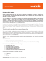
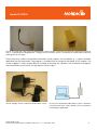
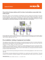
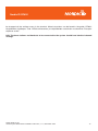
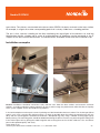
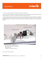
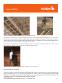
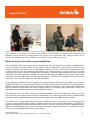
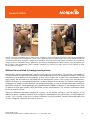
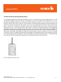
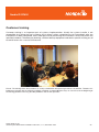
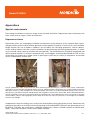
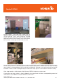
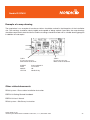
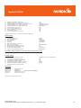
RF600
BASE STATION INSTALLATION INSTRUCTIONS
Contents
Introduction
5
Occupational safety
5
Preparatory procedures
7
Scheduling the necessary people
People involved in installations
Review or Site Survey
The information needed from cooperating parties
The necessary connections
Reserving a work area
Possible installation options
Connecting the base stations directly to workstations
Connecting the base stations with the ESERV-10 converters
Connecting the base stations with the help of workstations connected to the LAN
Pre-installation testing of equipment and cables
Checking the base station channel
Checking the channel of the handsets
Settings for the Viola Systems ESERV-10
Pre-installation test
Logging serial numbers
7
8
9
9
10
10
11
11
13
14
14
15
15
17
17
18
Equipment, tools and supplies
18
Installation procedures
20
Cabling
Network and corresponding connectors
Testability and serviceability
Naming and marking the base stations
Basic testing of the radio system installation
Malfunctions related to background systems
21
21
22
22
26
27
Customer training
29
Final documentation
30
Appendices
31
Special environments
Example of a map drawing
Other related documents
31
35
35
Default settings for the ESERV-10 FW program
36
Contact information
38
©2005 Nordic ID Oy
RF600 System Base Station Installation Instruction, v. 1.0, December 2005
2
���������������
Nordic ID Oy reserves itself the right to change the information mentioned in this guide without prior notification and
is not responsible for any damages possibly caused by the information presented in this guide.
All rights reserved.
The copying or translating to any language of the contents of this guide by any method is absolutely forbidden
without the written permission from Nordic ID Oy.
©2005 Nordic ID Oy
RF600 System Base Station Installation Instruction, v. 1.0, December 2005
3
���������������
Introduction
This guide is related to the installation of RF600 system base stations and related equipment. The work phases
and methods mentioned in this guide are recommended procedures when installing RF600 systems.
The installation can be achieved using other models as well, but Nordic ID Oy cannot accept liability for the
functioning of these kind of installations.
Nordic ID Oy reserves the right to charge current, updated hourly fees for the repair of erroneous installations
or the time used in troubleshooting these installations.
Occupational safety
For the proper execution of the work phases specified in this guide, personnel working on the installation
must:
•
know and comply with current electrical safety regulations for the parts
•
have undertaken training to perform similar types of installations or have participated in a
special training programme organised by Nordic ID Oy
•
comply with current safety regulations in the workplace for the application.
The installation may involve procedures that endanger the health of the person or persons carrying out
the installation work or of others not directly involved in the work. Typically personnel work on ladders or
stands, with the risk of falling or of items/tools dropping. This may cause injury and/or damage.
Installation personnel and the supervisor in charge of the installation and/or the installation company
must be covered by statutory insurance and any other insurance against risks, as deemed necessary. If
the person in charge of the installation work considers that procedures requiring a hot work card need to
be carried out, the supervisor should make sure that the personnel carrying out the work have valid hot
work cards.
Nordic ID Oy shall not be liable for any direct or indirect damages arising from carrying out the procedures
in these installation instructions.
WARNING! Current industrial safety regulations must be complied with at all times. Only approved
equipment must be used. Check the condition of the work equipment such as ladders and the like before
starting installation work. Do notcarry out dangerous work alone in an isolated area. Notify the customer
representative of where you are working and make sure that help is available if you need it.
©2005 Nordic ID Oy
RF600 System Base Station Installation Instruction, v. 1.0, December 2005
4
���������������
WARNING!
Do not leave small objects or tools anywhere in the reach of children. Do not leave wires or
tools anywhere that may be dangerous to bystanders (tripping, dropping , etc.).
N.B.!
All packaging materials, trash and waste should be disposed of as appropriate.. Recyclable
materials should be delivered to a recycling point wherever possible.
Picture: The ladders in the picture on the left do not comply with safety regulations in the workplace anywhere in
the world. Minimise personal injury by using only suitable ladders and stands. The ladder in the right side
picture is a better choice compared to the ladder in the previous picture, but still is not necessarily the best
option. With long ladders two people should be present, one to secure the ladder and hand over or take
tools and supplies, the other on the ladder.
N.B.! Whenever necessary, prevent bystanders from entering a dangerous area by segregating the area and
placing notices around it alerting personnel to the dangers. Check ladders before use. Before using a passenger hoist,
check who is liable for injury and damage and ask for a work instruction..
©2005 Nordic ID Oy
RF600 System Base Station Installation Instruction, v. 1.0, December 2005
5
���������������
Preparatory procedures
Scheduling the necessary people
Several experts are usually needed during the installation, particularly in installations that contain a preinstallation review, e.g. a Site Survey, and/or Final System Test and/or System Background Application
Training for end users. If these people cannot come to the installation site, the installation work will be
unfinished, un-checked or the schedule for the end of work will not be complied with.
Typically, the following persons may need to be called to the installation site:
•
representative of the final customer (access rights, keys, safety)
•
representative of the background application supplier (passwords, application testing)
•
IT manager of the final customer (using workstations, setting switches, access to the electric switch
gear cabinet, IP address definition).
If review and installation are done at the same time, the following personnel may also be needed:
•
electrician (installation of LAN and electrical plugs).
If the final customer has subcontracted the management and maintenance of the LAN network to a third
party or the manager in question is elsewhere (not on site), contact information for this person is needed for
any possible explanations over the phone.
Clearly, several people may be needed and getting them all to the installation site requires scheduling. The
absence of even one person or manager or difficulties in getting a phone connection may, in the worst case,
mean the installation remains unfinished.
The page below lists the vital people, background parties and tasks related to the installation. The list is
meant for guidance only. Each installation is unique.
©2005 Nordic ID Oy
RF600 System Base Station Installation Instruction, v. 1.0, December 2005
6
���������������
People involved in installations
Person
Anyone else *
Task
Installer of the RF600 system
Systems integrator
Service and maintenance
Line management
Outsourcing service
Technical manager for the final customer
Nordic ID Oy
The physical installation of the base
stations at specified locations and
testing the radio system whenever/
wherever possible.
Shop manager
Shop responsible
Final customer
Access rights
Providing a work space
Safety
Work equipment (ladder and hoist)
IT support person
Final customer
Service and maintenance
Line management
Outsourcing service
Background
expert
application
Use of workstation licenses, any
programme installations required
Setting of power switches
Systems integrator
Line management
Service and maintenance
Registering the handset onto the
background program
IP address definition of Viola Systems
ESERV-10 equipment and registering
onto the background program
PING testing the ESERV-10 IP
addresses
Training
Electrician
LAN network installer
Telephone fitter
Representative of the final customer
Outsourcing service
Service and maintenance
Local telephone company
230 VAC change work
LAN network change work
Network manager
IT support from the final customer
Service and maintenance
Outsourcing service
Remote programming of the network
switches
Trainer
Systems integrator
Line management
Trains the representative of the final
customer to using the background
application
* one or more
©2005 Nordic ID Oy
RF600 System Base Station Installation Instruction, v. 1.0, December 2005
7
���������������
Review or Site Survey
Before installation work, make sure that the site in question has undergone a review, i.e. a Site Survey.
The review involves measurement of filed radio reception, and in connection with the measurement the
definition of installation locations.
The review produces a map into which the RSSI value (Received Signal Strength Indicator value) indicating
reception is logged at regular intervals. In addition, ask the customer representative where, on the site,
reception is required. To guarantee the satisfaction of the final customer, it is generally recommended to
make sure that all back rooms, cellars and bomb shelters have been taken into consideration in the review,
even if this task is not strictly part of an installation review.
In some cases the review is made right before the installation by the party doing the installation. The review
must always be performed according to a separate “RF600 system – Site Survey Instruction” guide. The Site
Survey makes the review simpler and quicker. Additional information is contained in the guide mentioned
above.
The information needed from cooperating parties
The system is typically supplied by a systems integrator who at the same time may be the re-seller of the
equipment. In certain cases the delivery involves a device manufacturer or several manufacturers (Nordic
ID Oy, Viola Systems Oy), re-seller, systems integrator or company providing the background application as
well as the customer’s Line management.
Typically, at least the following information should be requested beforehand from the parties mentioned
above:
General information
•
•
Copies of the blueprints of the installation site
Instructions for the installation targets for base stations (measured or otherwise verified)
Information relating to RF600 handsets and chargers
•
•
•
•
•
The channel to be used
The setting value for re-send times
The setting value for the waiting time
The password for the settings menu
The locations where the chargers should be placed
If Viola Systems Oy ESERV-10 converters are used
•
•
•
IP addresses
Mask
Gateway
©2005 Nordic ID Oy
RF600 System Base Station Installation Instruction, v. 1.0, December 2005
8
���������������
Other issues to clarify
•
At the installation site, make sure that all rooms and storage spaces to be included in reception
areas have been reviewed.
The necessary connections
If the review was performed appropriately, the intended base station installation points were fitted with
the necessary connections (free electrical plug 230VAC and a free LAN plug, if Viola Systems ESERV-10
devices are used). If this was not done, the installation cannot be carried out correctly.
In this case, installation must be delayed until all the necessary procedures have been carried out.
Reserving a work area
Next you must segregate a suitable area that you can lock, preferably protected from bystanders, for
preparatory procedures. Typically the representative of the final customer (shop manager) gives the fitter a
so-called back room, which is separate from the shop or storage facilities.
The work area should include enough table space and a few 230VAC mains connections.
Picture: The work area is typically located in the so-called back room.
The picture on the left shows a typical situation. A laptop (equipped with Piccopla program) and the necessary voltage
sources are ready. These are needed, for example, to change the base station channels and test the equipment before
actual installation. Tools, assembly supplies and note-taking equipment as well as a mobile phone are also needed.
The picture on the right shows an important work phase to be done before the installation: checking the delivered
supplies and equipment. The devices and supplies delivered to the installation site should be checked in connection
to type, model and functioning before moving on to the actual installation work.
©2005 Nordic ID Oy
RF600 System Base Station Installation Instruction, v. 1.0, December 2005
9
���������������
Possible installation options
The RF600 system can be installed in several ways. A simple method suitable in particular for small targets is
to install the base stations directly in the workstations. In more complex cases (large reception area, remote
control needed) the base stations are connected to the background system with special RS-232/TCP-IP
converters, in turn connected to the existing LAN network. Both methods involve certain considerations.
These are explained in more detail in the following sections.
Connecting the base stations directly to workstations
The RF600 base station can be connected directly to a workstation that includes a free male 9-pin D
connector equipped with a RS-232 connector. The base station is connected to the workstation usually
with the grey 5m long connection cable provided. In addition, the base station voltage source is connected
to the base station.
If the connection distance is over 5 meters, a separate extension cable is required. It can also be connected
with a special connector. When using this method, the largest connection distance allowed is about 30-50
meters. The extension cable set includes a special connector that enables connecting the voltage source to
the extension cable at the workstation. In this case you don’t have to wire up the 230V cables, for example,
to the ceiling on the shop side.
N.B.! The back room is usually not the optimal installation location for a base station. The base station
should generally be installed in a central place in the reception area. When necessary, use an RS-232
extension cable or a separate RS-232 amplifier.
Picture: Standard connection cable for RF600 base
stations.
Picture: The extension cable set for the RF600 base station
includes a connector for extensions as well as a separate
piece equipped with a voltage source connector. This
piece is installed on the workstation end of the cable.
©2005 Nordic ID Oy
RF600 System Base Station Installation Instruction, v. 1.0, December 2005
10
���������������
Picture: The extension cable set for the RF600 base station includes a connector for extensions (picture on the left) as
well as a separate piece equipped with a voltage source connector, which is installed on the workstation end of the
cable (picture on the right).
Please note that a direct workstation connection usually requires the installation of a special PLClient
application on the workstation. The program is available free of charge on the Nordic ID Oy website. The
system supplier is mainly responsible for installing and testing the software. The installation of programs
onto workstations or the server usually requires access rights.
Picture: Voltage source (7.5VDC) for RF600 base station.
Picture: The simplest possible RF600 system is based on
connecting the base station directly to the workstation
containing the application.
©2005 Nordic ID Oy
RF600 System Base Station Installation Instruction, v. 1.0, December 2005
11
���������������
Connecting the base stations with the ESERV-10 converters
You should use RS-232/TCP-IP converters if the system reception area is large, there are many workstations
or you do not want to utilise them in the installation and particularly if you want a remote control possibility,
for example, from the shop chain IT department using a Telnet connection. The prerequisite for using the
converters is that the installation site has a LAN network. The customer or systems integrator is the main
responsible for the LAN network installations and functioning.
The RF600 base stations can be connected to the LAN network using a suitable converter. Nordic ID Oy
recommends and supports the ESERV-10 converter by Viola Systems. The converters of other manufacturers
may also be used, if compatible.
The base station is connected to the ESERV-10 converter with a black 2-meter long connection cable
supplied with the converter. The cable connects the base station voltage source input voltage (7.5VDC) to
the converter, so the converter does not require a separate voltage source. Connect a network cable to the
LAN connector of the converter. Install the other end of the cable to a free or specified network connection
point. The port settings of any possible switches should be adjusted to position 10/Half for those ports to
which the ESERV-10 converters are connected.
Picture: RF600 base stations can be connected to the server with RS-232/TCP-IP converters. The converters are
connected to the LAN network. Typically a PLServer application is installed on the server. The functions of the PLServer
application are also included sometimes inside the customer application.
©2005 Nordic ID Oy
RF600 System Base Station Installation Instruction, v. 1.0, December 2005
12
���������������
Connecting the base stations with the help of workstations connected to the
LAN network
RF600 base stations can be connected to a background system by utilising the workstations connected
to the LAN network. In this case, the serial traffic is converted to TCP/IP traffic with the help of a separate
PLClient application, and the traffic is transferred to a server, where the PLServer application relays the
traffic forward to a background program. The PLServer application is responsible, for example, for routing
the background system answer messages to the base station closest to the handset.
Picture: RF600 base stations can be connected to the server by utilising the workstations, the LAN network cards in
the workstations and the LAN network. In this case, you typically install the PLClient application to each workstation
and the PLServer application to the server.
Pre-installation testing of equipment and cables
The equipment to be installed at the installation site are either brought by the fitter or have been delivered to
the installation site beforehand. You should open the delivery packages and make sure that the necessary
equipment and their supplies are ready to be installed.
In addition, it is recommended to turn on the power for all the equipment and to check all connection cables
individually before installation. Similarly, connect the Viola Systems ESERV-10 devices individually to a free
network connection and check the settings at least for the IP address by utilising the workstation of the final
customer and the PING command.
This saves time and effort by preventing the installation of malfunctioning equipment, which then has to be
replaced.
If the handsets have been delivered to the installation site, unpack them and fit the batteries. The serial
numbers of the handsets should be recorded in the final documentation. When necessary, the channel of
©2005 Nordic ID Oy
RF600 System Base Station Installation Instruction, v. 1.0, December 2005
13
���������������
the handsets must be changed, as well as the number of send times and the waiting time per send time.
Unless otherwise specified by the background application expert, use the default values until you can test
the installation. At this point you can define new default values together with the background system expert,
and these values can finally be programmed for each handset.
The settings are protected by activating the password protecting the menu. The password is defined by the
background system expert or the representative of the final customer. The password should be recorded
for final documentation. More information on changing the settings can be found in ”RF600-käsipäätteen
käyttöoppaassa”.
Checking the base station channel
RF600 base stations supplied by Nordic ID are ready for use, but since channel no. 3 is used as the default
channel, in most cases the channels of all base stations connected to the system should be changed (the
available channels are 1-7, and the capacity of channel 7 is a little smaller than other channels).
Usually the channel is defined by the Line management of the final customer or the systems integrator who
is responsible for delivering the entire system. The fitter should ascertain whether a corresponding RF600
system is in use next-door to the installation site. If there are other Piccolink RF600 users next door, make
sure that the systems channels are not the same. Greatest reliability is obtained by setting the channels
close to each other but skipping one out (1-3-5 or 2-4-6).
The channel of base stations can be changed by connecting the base station with the grey 5-meter long
RS-232 cable provided to the free RS-232 connector in the PC. The Piccopla program should be installed
in the computer. You can change the channel from the program menus.
N.B.! The base stations and handsets to be connected to the system should have identical channel
settings.
Checking the channel of the handsets
RF600 handsets supplied by Nordic ID are ready for use, but since channel no. 3 is used as the default
channel, in the majority of cases there will be a need to change the channels of all handsets connected
to the system (the available channels are 1-7, and the capacity of channel 7 is a little smaller than other
channels).
Usually the channel is defined by the Line management of the final customer or systems integrator who
is responsible for delivering the entire system. The fitter should ascertain whether a corresponding RF600
system is in use next-door to the installation site. If there are other Piccolink RF600 users next door, make
sure that the system channels are not the same. Greatest reliability is obtained by setting the channels of
systems close to each other but skipping one out (1-3-5 or 2-4-6).
The channel of the handsets can be changed by connecting the handset with the grey 5-meter long RS232 cable provided to the free RS-232 connector in the PC. The Piccopla program should be installed in
the computer. You can change the channel from the program menus. The settings of the handsets can
©2005 Nordic ID Oy
RF600 System Base Station Installation Instruction, v. 1.0, December 2005
14
���������������
be changed via the settings menu in the terminal. More instructions can be found in the guide “RF600käsipäätteen käyttöopas” and “RF600-tukiasemien ja käsipäätteiden asetuksien muuttaminen Piccoplaohjelman avulla”.
N.B.! The base stations and handsets to be connected to the system should have identical channel
settings.
©2005 Nordic ID Oy
RF600 System Base Station Installation Instruction, v. 1.0, December 2005
15
���������������
Settings for the Viola Systems ESERV-10
Nordic ID and Viola Systems have translated a special FW program version (2.1.6 NORDIC ID) containing
the correct setting values for the use of the RF600 system. The default settings of the background system
may need to be changed. A typical example is the need to change the setting value defining the traffic
method from a TCP to a UDP value.
In connection with the installation, it is usually necessary to define at least an IP address, mask and gateway
and the application IP address and port where the ESERV-10 contacts. Customer IT support personnel
should provide the necessary information together with the Line management and/or background application
supplier representative.
The ESERv-10 device is programmed by connecting the so-called null modem cable device directly to the
RS-232 port of the PC (HyperTerminal method), by connecting the so-called cross-connection cable device
directly to the network card connector of the PC (Telnet method) or by connecting the device with a normal
network cable to the LAN network plug at the installation site (Telnet method).
Additional instructions can be found in the guide ”Viola Systems ESERV-10 User Handbook”, ”Viola Systems
ESERV-10 Getting Started Handbook” and in the document ”RF600 system – Viola Systems ESERV-10
– Settings of the HyperTerminal program”.
Default values are listed in the Appendix to this guide “Viola Systems ESERV-10 default settings”.
Pre-installation test
When base stations, handsets and Viola ESERV-10 devices have been checked and the default settings
changed as necessary, a pre-installation test should be carried out. The purpose of the pre-installation test
is to make sure that all equipment to be installed is operational before doing any actual installation work.
The pre-installation test can be carried out earlier by utilising the background application as soon as it is
functional. In this case the base station and the connected ESERV-10 are connected to a free/suitable LAN
network connector with a network cable. When the ESERV-120 has connected to the network and the
background application has recognised it (the IP address of the ESERV-10 normally needs to be logged
into the background system beforehand), a log-in window should appear in the handset display when any
F key is pressed (the CommID of the handset generally needs to be logged into the background system
beforehand). If the supplier of the background system has provided a user name and password, you can
also test by using the application.
Another way to do the pre-installation test is to utilise the RF600 test program (or RF600 demo programs)
installed on a PC (test laptop). Each base station is connected to the voltage source and to the PC with
the RS-232 cable, after which you the functioning of all the equipment can be verified with the help of the
handset and the test program. The handsets, base stations and voltage sources are gone through one by
one. At the same time base stations can be labelled, if this has not yet been done.
Viola Systems ESERV-10 devices are tested in the following way. First connect a 2-meter Viola Ethernet
cable between the ESERV-10 device and the base station. Then connect a voltage source (7.5VDC) to the
©2005 Nordic ID Oy
RF600 System Base Station Installation Instruction, v. 1.0, December 2005
16
���������������
base station. A green LED should come on in the base station and in the ESERV-10. If possible, the ESERV10 should be connected to the LAN network of the installation site, after which a PING test can be carried
out by using a programmed IP address (which requires the use of a network host or a background system
or the presence of Line management personnel).
N.B.! In normal use ESERV-10 device DIP switches should be in the “OFF” position (lowest position).
Logging serial numbers
At the same time, write down the serial numbers of the base stations and corresponding devices that have
serial numbers. As the installation progresses, clearly mark the installation locations on the map as well as
the serial numbers of the devices installed in the locations.
Picture: Write down the serial numbers of the handsets, install batteries in the handsets and, if necessary, change
the settings according to the requirements of the installation location. The settings menu can be protected with a
password. Finally place the handsets in the charger, so that you can check the charging function and charge the
handsets fully for any possible training.
Equipment, tools and supplies
A typical installation requires the following supplies, tools and devices:
Background information and guides
At least the following background information and guides are needed in the installation:
•
RF600 base station installation instruction (this handbook)
•
RF600 handset user guide
•
the map describing the reception area, drawn in connection with the review
©2005 Nordic ID Oy
RF600 System Base Station Installation Instruction, v. 1.0, December 2005
17
���������������
•
•
•
the devices, cables, voltage sources and supplies ordered for the installation
contact information of the contact persons and responsible parties (see section “Scheduling the
necessary people”)
passwords and access rights for testing the customer background system.
Tools
In the installation, you need at least the following tools:
•
scissors
•
side cutting pliers
•
cleaning rags (3M VHB Surface Cleaner Sachets)
•
a ladder or a hoist (a model complying with safety regulations in the workplace).
Fixing and marking supplies
At least the following fixing and marking supplies are needed in the installation:
•
•
•
cable ties (different sizes, back and white)
Velcro type sticker tape (3M Scotchmate™ SJ 352 D)
installation stands for the base stations
•
DYMO type marking device for labelling the base stations and installation locations or stickers
printed beforehand.
Testing and programming equipment
At least the following testing and programming equipment are needed in the installation:
•
laptop with the Piccopla program installed and with 1 RS-232 connector free or alternatively
access to the final customer workstation and the right to use it; the workstation should have the
Piccopla program or it should be possible to install the program.
•
Piccopla program in a USB memory stick or on a CD-ROM
•
charged AA size batteries (2 pcs NiMH 1600 mAh) or 2 pcs of AA size 1.5V batteries
•
1 base station connection cable (5m long gray RS-232 cable)
•
1 Viola Ethernet cable (2m black RS-232/RJ45 cable)
©2005 Nordic ID Oy
RF600 System Base Station Installation Instruction, v. 1.0, December 2005
18
���������������
•
1 voltage source for programming the base stations (7.5VDC)
•
1 voltage source with Viola Systems ESERV-10 connector (7.5VDC)
•
1 RS-232 null modem cable
•
1 cross-connection cable (LAN)
•
1 network cable (LAN)
Supplies related to safety
At least the following safety-related supplies are needed in the installation:
•
Notices and chains to rope off the dangerous areas
In addition you may need
•
Site Survey tool (for the review)
•
1 base station (for testing and possible review)
•
1 handset (for testing and possible review)
Installation procedures
The installation can be started when the pre-installation test has been performed, the base stations and
ESERV-10 devices have been marked with stickers and the setting information has been changed if
necessary.
The installation locations of the base stations are examined, preferably in a specific order (from the cellar
to the top floor or the other way around, one floor at a time). Identification codes (STAT 1, STAT 2, etc.) are
used in sequence.
At the installation location itself, first examine how the devices should be installed and estimate the free
lengths of the necessary cables. The extra cable lengths are tied up in a suitably tight bundle and then
locked with cable ties, and the extra tails are cut off the ties.
Then cut suitably long pieces of the Velcro band and attach them to the base station and the ESERV-10
device in the appropriate places in such a way that the devices can be installed on the intended installation
surface (rail, groove, grid, etc.). The lengths of the Velcro straps should be maximised and two Velcro pieces
should be used side by side in the case of the ESERV-10.
The aim is to prepare a situation in which you can see the base station and ESERV-10 device signal lights
©2005 Nordic ID Oy
RF600 System Base Station Installation Instruction, v. 1.0, December 2005
19
���������������
standing on the floor. Next clean the installation surfaces with suitable equipment and materials, so that the
Velcro strap attachment is as fast as possible. A good choice is a special individually packed cleaning rag
dampened with cleaning agent. The surfaces must be dried if wet (water, cleaning agents).
Next install the equipment one device at a time, and then attach the cables. The extra cable lengths are
bundled up at this stage at the latest and tied together neatly with cable ties, the ends of which are cut off.
The cable between the base station and the ESERV-10 device is attached in a suitable way from a few spots
to the fixing surface (rail, groove). This prevents devices falling even if the Velcro tape fails.
The labels printed earlier are attached, one on the base station, one on the ESERV-10 and one in the near
vicinity of the installation location. The labels should be legible from a standing position.
Finally connect the voltage source to the mains voltage (230VAC) and the weak current plug of the voltage
source to the base station connector. The green light in the base station should come on, as well as the
green light in the ESERV-10 device. Finally connect the LAN network cable to the ESERV-10 device network
connector, at which point the green signal light should start blinking slowly in step. After this the signal
light will start to blink irregularly and quite fast. This means that the ESERV-10 device has been fitted to the
network.
N.B.! Make sure the appropriate switches have been turned to position 10/Half.
The installation is completed one base station at a time. Mark the base station serial number, ESERV-10 MAC
address and their joint identification (STAT 1 or corresponding) on the blueprint. Collect all extra packaging
materials and trash and dispose of them appropriately at the waste collection point or for recycling.
Now test the connection between the background application and the RF600 system. This is done by the
final customer IT support personnel and/or Line management representative and/or the representative of
the background application.
The fitter should be available until the functioning of the installation has been verified.
Finally prepare the documentation and remove the tools and supplies from customer facilities.
Cabling
The cabling of the LAN networks should be subcontracted to knowledgeable installation staff. High-class
materials should be used. The use of extension cables and all kinds of “riggings” is not recommended and
may cause the guarantee to become invalid before the period expires. If necessary, contact Nordic ID Oy
technical support for further information about extension cables.
Network and corresponding connectors
The most common problems relate to the LAN network of the installation site. The network may contain
switches with settings that do not correspond to the settings required by the Viola Systems ESERV-10
©2005 Nordic ID Oy
RF600 System Base Station Installation Instruction, v. 1.0, December 2005
20
���������������
device (10/Half).
There have also been cases where the installation site contains “ghost switches” installed later that are
unknown to the customer’s IT maintenance staff. In these cases, troubleshooting is practically impossible,
unless the installation site includes both the final customer’s IT manager and the IT maintenance
representative.
Picture: The functioning of the installation site switches needs to be clearly defined. The installation cannot progress
unless the customer’s network manager or IT representative is present.
Testability and serviceability
A few essential matters need to be taken into consideration to simplify maintenance. Base stations and
Viola Systems ESERV-10 devices should be installed in such a way that their signal lights are visible from a
standing position. They should be fitted so they can be removed easily and quickly. The labels attached to
the devices should be legible from a standing position.
The use of a Velcro type sticker tape for mounting the device casings is recommended, but the installations
should be secured. This can be done by attaching jumper cables and network and power feed cables
appropriately by tying them with cable ties to the mounting rails and light rails. A proper installation enables
any individual device (base station, ESERV-10, voltage source) to be replaced easily and quickly without
touching the other devices.
Naming and marking the base stations
To simplify systems servicing, maintenance and help desk type services, each base station should be
labelled with a clear name (STAT 1, STAT 2, etc.). The markings should be made with a large enough DYMO
©2005 Nordic ID Oy
RF600 System Base Station Installation Instruction, v. 1.0, December 2005
21
���������������
type sticker. The stickers are attached to the base station, ESERV-10 device and next to the base station,
for example, in a light rail or other corresponding point that is clearly visible from a standing position.
The aim is that a person standing on the floor monitoring the signal lights of the devices can read the
identification without a ladder and in cases of malfunctioning can telephone service personnel or the IT
support for the base station identification. The identifications should be written onto the installation map.
Installation examples
Picture: Installations should be carried out neatly and with care. Often the base stations are located in customer
facilities, so untidy installations impact negatively on the customer image, the professional skill of the fitter, the quality
of the system supplier and on the Nordic ID Oy products.
In the left-hand picture at the top, the arrow is pointing to a label attached to the base station. The sticker tape (Velcro
type) is cut in such a way that the sticking surface is as large as possible. Near the ceiling, the mounting rails are very
dusty and the mounting point should be cleaned with a dampened rag or by using a suitable cleaning agent (spray
bottle) and rag. The mounting point should be dried before fitting the device. Devices are preventing from falling even
if the sticker tapes fails by joining the cables together and securing them to the rail with cable ties. This also allows
parts to be replaced quickly and easily.
©2005 Nordic ID Oy
RF600 System Base Station Installation Instruction, v. 1.0, December 2005
22
���������������
The arrow at the upper right points to the label attached to the mounting rail.
On the lower left, the arrow points to a properly secured LAN network cable, originally too long and therefore bundled
up and secured with a cable tie. The extra ends of the cable ties have been cut off.
On the lower right the arrow points to a base station installed in storage where roller cages are handled. The installation
height of the base station must be checked and the base station should not be hit by the roller cage. The ceiling has
been partly lowered in the installation site, but the base station should still be installed as low as possible due to
reception.
Viola Ethernet 2m connection cable
Voltage source (7.5VDC)
Voltage source cable
Network cable
DIP switches and LEDs
point downwards to the floor
Base station antenna should be placed
below the lower level of the mounting rail
Base station LEDs
readable when standing on the floor
Picture: Details of the installation.
©2005 Nordic ID Oy
RF600 System Base Station Installation Instruction, v. 1.0, December 2005
23
���������������
Picture: Installation location conditions affect the assembly method.
The picture on the left shows a typical ceiling grid. The base station should be placed hanging from the connection
wire in such a way that the base station antenna tip is about 25-30cm below the grid level. Particularly in relation to
metallic grids, the distance should be sufficient to avoid interference. In the picture, the Viola Systems ESERV-10 has
been mounted with a cable tie. Better is sticky tape such as Velcro.
The picture on the right shows how the sticky tape has been attached to the lowest part of the base station, so the
base station can hang as far as possible from the bottom edge of the rail.
Picture: The wall installation support enables installations on wall surfaces.
Final testing of the installation
The extensive final installation testing of the RF600 system includes connection tests for the radio terminal
devices, network tests of any Viola Systems ESERV-10 devices (with the PING command) and testing
between the background system and the RF600 system (the background is tested with handsets). On
installation day, all the required personnel should be available.
©2005 Nordic ID Oy
RF600 System Base Station Installation Instruction, v. 1.0, December 2005
24
���������������
Picture: The installation of the RF600 system has not been completed until connection and application tests have
been carried out. In the picture on the left the serial numbers of the hhandsets are logged into the background and
application testing and training is being prepared. In the picture on the right PING testing is being carried out on the
Viola Systems ESERV-10 devices installed. This test enables network traffic to be verified.
Basic testing of the radio system installation
The functioning of the radio system can be tested either with the help of the background application or
in such a way that the base stations are put into Site Survey mode one at a time (in this case other base
stations should be shut down). The test should be carried out in such a way that the background system
is utilised, because this also provides information on the response time (it may be necessary to change
the waiting time and/or send time setting value of handsets). Generally, the background system cannot be
used unless you have obtained a suitable user name and password. In addition, the handset serial number
(CommID) should be registered in the background program. The Site Survey method involves much more
work and is usually not possible within specified schedules.
If the background system does not respond, the handset and base stations may have been set to function
on different channels or the connection between the base station and the workstation or the Viola Systems
ESERV-10 device may be broken (cable malfunction or device malfunction). It is also possible that the Viola
Systems ESERV-10 device has the wrong settings and/or its IP address and/or port to be used by the
application have not been registered in the background system.
Other possible faults are switch settings, connection problems with the background system server and
the absence of the handset CommID from the definition file of the background system. Troubleshooting
generally requires cooperation between the personnel specified at the beginning of this guide.
If a malfunction is suspected in the Viola Systems ESERV-10 device, the devices can be tested via the
customers workstation or with the help of a laptop connected to the customer LAN network. The ESERV-10
device responding to the PING command usually functions correctly, so if the connection cable between the
ESERV-10 and the RF600 base station is ok and if the base station radio terminal is functioning normally,
the fault is in the background system or in its settings.
©2005 Nordic ID Oy
RF600 System Base Station Installation Instruction, v. 1.0, December 2005
25
���������������
Picture: The final installation test of radio system reception can be carried out easiest by utilising the background
system. First log into the background system. This is generally done by inputting the user name and password with
the handset. Next walk through the edges of the reception area and read the bar codes of products for example by
using inventory or the product query application. The reading should be done in difficult places with your back to the
base station. If the background system responds sufficiently fast and no messages are lost, the installation is ready
for the radio system part.
Malfunctions related to background systems
Malfunctions related to background systems are not common, but do occur.. For the fitter, the problem is
usually that there is no previous information on the background system. For background systems usually the
CommIDs must be defined for the handsets so they can be used in the system. The serial numbers of the
base stations do not need to be registered into the background system. If the system uses Viola Systems
ESERV-10 devices or corresponding converters made by another manufacturer, you should usually register
or define the IP address of each device in the background system, as well as the application port number for
the ESERV-10 device. Correspondingly you should define the ESERV-10 devices in the background system
IP address and the port number which the RF600 system should contact. The switches in between should
be set to position 10/Half.
There are differences between background systems, so the default settings in the FW program of the
ESERV-10 device should be checked and changed to correspond to the requirements of the background
system. This is usually a task for the systems integrator. During installation contact information about the
systems integrator should be on hand at all times.
©2005 Nordic ID Oy
RF600 System Base Station Installation Instruction, v. 1.0, December 2005
26
���������������
Troubleshooting routing malfunctions
If a background application related to the RF600 system is not utilising the PLServer application or if an old
version of the program is being used, the functioning of the system installed may be defective. A fast way
to check the routing function is to stand near the base station or under it in such a way that you can see
the base station LEDs. Now, when you use the handset, the background application should respond to the
handset in question through the base station. In this case the signal light on the base station (red TX-LED)
blinks a few times. If necessary, carefully unscrew the handset antenna by turning it counter-clockwise
and repeat the test. If the red LED doesn’t blink, there is most likely something wrong in the background
application routing, or the network or other connection from the base station in question to the ESERV-10
converter or forward of the network through the switches to the server. Faults can be caused by defective or
badly connected cables, damaged units, defective network cables, incorrect settings in the units or network
switches or routers or inadequate initialisation information in the application on the server (handset CommID
has not been registered, the IP address or port of the ESERV-10 has not been defined, etc.). Troubleshooting
can take a lot of time and generally requires close cooperation between several parties.
Picture: RF600 base station LEDs.
©2005 Nordic ID Oy
RF600 System Base Station Installation Instruction, v. 1.0, December 2005
27
���������������
Customer training
Customer training is an important part of systems implementation. Usually the system installer is not
responsible for training the final customer, but training is often scheduled to start immediately after the
installation has been completed, which adds pressure to performing the installation successfully within the
specified schedule. Therefore pre-planning, sufficient backup equipment and device-specific training are all
essential factors for a successful outcome.
Picture: The training of the final customer is usually scheduled to take place right after the installation. Therefore it is
important to comply with the original installation schedule. A responsible fitter stays on site at least at the beginning of
the training period to solve any possible problems and answer questions.
©2005 Nordic ID Oy
RF600 System Base Station Installation Instruction, v. 1.0, December 2005
28
���������������
Final documentation
The aim of the final documentation is to gather together all the essential information on the installed
system into one binder. The final documentation is needed in connection with future installation changes,
troubleshooting of malfunctions in the system and to support help desk type functions.
The following information should be included in the final documentation:
•
updated map of the installation site
•
list of the base station serial numbers
•
list of the handset serial numbers
•
setting values of the handsets
•
the password for the settings menu of the handsets
•
a list of IP addresses, MAC addresses and the given base station specific names.
The base station installation locations, serial numbers, IP addresses and Viola Systems ESERV-10 device
MAC address (on the sticker on the outer side of the casing) and the base station nickname (STAT 1, STAT2,
etc.) should be marked on the installation site map. In addition, you should draft a separate base station
serial number list to which the corresponding information is added. The serial numbers of the handsets
should also be recorded. In connection with this, write down the FW version of the handsets (instructions
on checking the FW version are in the guide “RF600-käsipäätteen käyttöopas”). If the setting values of
the handsets are changed from the default values, the changed values should be recorded, as well as the
password for the setting menu, if used.
Wherever possible, you should keep copies of the final documentation. One copy should be held by the
representative of the final customer on the installation site, one copy delivered to the systems integrator
and/or background system representative and one copy, if possible, delivered to Nordic ID Oy Technical
Support. One copy should be held by the installer.
The final documentation should specify the installer and installing company names and contact
information.
©2005 Nordic ID Oy
RF600 System Base Station Installation Instruction, v. 1.0, December 2005
29
���������������
Appendices
Special environments
Even though installations are always unique, there are some similarities. Department store environments are
often similar and so are gas station environments.
Department stores
Department stores are challenging installation environments mainly because of the separate back rooms,
storage facilities and the cellar facilities generally used as goods-in facilities. In most cases, the installation
height requires the use of ladders. Problems are caused by the LAN plug placement, switch cabinets,
switch settings and the fact that usually installation can be carried out only during opening hours, in which
case customer safety needs to be taken into consideration. The installation area should be segregated and
notices placed around it. Customers and particularly small children should not be allowed to enter an area
where tools may drop from a height. Often a special pass (RFID key or similar) is required for unescorted
access to backrooms and the like.
Picture: Department store environments are often confusing and something of a maze in their layouts. Department
store cellars usually include large bomb shelters used as storage facilities. The Site Survey can be carried out with the
door open, which is usually enough to ensure that reception also covers the inside of the bomb shelter. In this case, the
Site Survey results documentation should specify that reception measurements were made “WITH THE DOOR OPEN”.
Usually installations have to be carried out during the opening hours of the department store. The picture on the right
shows ladders, notices and segregating chains ready to ensure the safety of customers, even though the installation
work has yet to begin.
In department stores the ceilings are usually of the intermediate ceiling type (grid or similar). Sometimes the
opening of the grid is so small that accessing the plugs (LAN and 230VAC) located in the space above it can
be difficult. The grids are usually dusty, so before attaching any sticker-surfaced materials or identification
labels, clean the installation surface with suitable methods.
©2005 Nordic ID Oy
RF600 System Base Station Installation Instruction, v. 1.0, December 2005
30
���������������
Gas stations
Nowadays gas stations resemble each other very much regardless of the oil company.. Normally the gas
station has a shopping area, and there is a line of coolers on the back wall. The doors of the coolers are
made of glass. The walls and back door of the cooler space are thick and insulated, creating massive
barriers to radio signals, and this should be taken into consideration when placing the base stations. The
backroom of the gas station includes a workstation to which you usually want to directly connect the base
station. In addition, you usually want the handsets to function outside as well, at least in connection with
inventorying the different kinds of liquid products in front of the shop. In the summertime there may be
more products outside (grill products, summer furniture, etc.). You should be particularly careful with the
oil room. Usually the oil room is located at the side of the building or behind it and has its own front door.
Since the space is fire protected, the walls are naturally also thicker. Usually the base station has to cover
the functioning of the oil room.
Large gas stations these days also contain even a sizeable restaurant space, where the cash desk sells
tobacco products and magazines, so the handset should also work on the restaurant side. The kitchen
of the restaurant includes several storage spaces, some of which are cold spaces. Usually it is difficult or
impossible to provide coverage in freezer rooms. One solution is to ask the customer to use a bar code
system in such a way that the freezer room door is open. Another option is to move the things out of the
freezer room for a while.
Even in small gas stations you should not settle for a base station installed next to the workstation in the
backroom. Creating sufficient coverage for the entire shop space and the gas station building almost always
requires the base station to be in a central location in the shop, also providing “visual contact” from the base
station to the glass doors of the coolers.
In this case you generally need an RS-232 type extension cable (direct RS-232 cable, 9-pin D connectors,
female at one end, male at the other ). In tests, the connection of the RS-232 may be via a cable of dozens of
meters, where a desktop is used. If the base station is a laptop, the connection length is essentially smaller
due to differences in the computer RS-232 connection driver circuit.
Picture: In front of the gas station, often there are products outside the customer wants to inventory without having
to carry the products separately into the shop. Coverage should extend a little outside the shop, at least in the front of
the building. In the shop space, the base station should be placed in such a way that there is “visual connection” from
the base station to the cooler glass doors. This ensures that there is coverage for the rear parts of coolers.
©2005 Nordic ID Oy
RF600 System Base Station Installation Instruction, v. 1.0, December 2005
31
���������������
Picture: Behind or at the side of gas stations there is
generally a door to the oil room. The room is fire-protected,
so field coverage in this space should be checked
carefully. This gas station has a cellar, but the customer
forgot about it at the review. Products in the cellar need to
be inventoried, so coverage should include the cellar.
Picture: Typical ”incorrect” installation. The base station is attached to the wall, in addition to which on the other side in
the near vicinity there is a metal-surfaced one-way mirror and the shop space on the other side of the mirror. The shop
space includes a metal-background shelf construction installed later. Coverage in the shop is poor with this type of
installation. The base station should generally be installed in the shop space in a central location and to the ceiling.
If the shop contains a LAN network, Viola Systems ESERV-10 devices can be used.
If more than one base station is clearly needed in the shop, there must be a corresponding amount of
workstations or an ESERV-10 based solution must be used.
©2005 Nordic ID Oy
RF600 System Base Station Installation Instruction, v. 1.0, December 2005
32
���������������
Warehouses
Warehouses usually have a very high ceiling, and the rafters are also fairly deep (several meters below the
ceiling itself). Ladders cannot be used, so a hoist is required. Hoisting with forklifts is generally not allowed
by safety regulations. The equipment is almost always ordered specifically from a supplier not involved in
the installation work. Be sure to book the hoist in time.
Metallic shelves and other structures restrict coverage. In addition, warehouses containing, for example,
liquid substances, such as alcohol, effectively suppress the 433MHz frequency. The Site Survey should be
carried out carefully when the warehouse is fully fitted and close to maximum storage capacity.
In the case of concrete rafters, when base stations are installed in the ceiling, they should be installed low
enough and in such a way that the base station antenna is at least 30cm below the lower level of the rafter.
If handsets are used only at floor level, installing the base stations on the walls may be a better solution than
on the ceiling. If the warehouse uses forklift trucks with protective cages (and protective roof), the signal
of a base station located too high can be disrupted by the metallic protective grid, causing disturbances.
When a base station is installed on the wall at a height of about 2 m., there is a “visual contact” with the
handset inside the forklift, but if the base station is installed on the ceiling, the metallic protective ceiling of
the forklift between the handset and the base station causes a disturbance. In the worst case, radio traffic
is prevented.
Notify the customer that when it comes to handsets installed in forklifts, in certain cases (when the forklift
is moving with great speed) disturbances may occur. Generally drivers use the handset while the forklift is
stationary, so in practice the problem hardly ever occurs.
For forklift use, recommend to the customer the use of a special handset stand to prevent the handsets
from falling.
Picture: The stand for the RF600 and terminal, installed by forklift.
©2005 Nordic ID Oy
RF600 System Base Station Installation Instruction, v. 1.0, December 2005
33
���������������
Example of a map drawing
The map below is an example of how base stations should be marked in the blueprints of the installation
site. The markings should be clearly legible and capable of being copied. If possible, the map drawings
should be requested in electrical format and the markings should be made with a suitable drawing program
in addition to hard copies.
TUKI 1
IP 123.123.123.123
MAC 00:06:70:00:0E:21
KOHDE:
PVM:
ASENT:
YRITYS:
TUKI 2
IP 123.123.123.124
MAC 00:06:70:00:0E:22
Asennuskohde X
13.12.2004
HS
Nordic ID Oy
Other related documents
RF600 system – Base station installation instruction
ESERV-10 Getting Started Handbook
ESERV-10 User’s Manual
RF600 system – Site Survey instruction
©2005 Nordic ID Oy
RF600 System Base Station Installation Instruction, v. 1.0, December 2005
34
���������������
Default settings for the ESERV-10 FW program
The following default settings are valid for Viola Systems ESERV-10 FW version 1.0 Nordic ID.
NORDIC ID
RF600 SYSTEM - VIOLA ESERV-10 SETTINGS (FIRMWARE)
N.B.! The settings are related to version 1.0.0 Nordic ID
------------------------------------------------------------------Viola Systems ESERV-10 configuration mode
------------------------------------------------------------------1)
2)
3)
4)
5)
6)
7)
8)
D)
A)
Serial settings
Network settings
Transmit algorithm
Terminal communication mode
E-mail settings
AT commands settings
Security
Address book
Default settings
About (system)
S)
Q)
E)
H)
C)
Save settings
Quit without save
Save & Exit
Help
Back
Serial settings
1)
2)
3)
4)
5)
6)
Speed (bps)
Data bits
Stop bits
Parity
Flow control
RS-485 Duplex
19200
8
1
N
N
FULL DPLX
Network settings
1)
2)
3)
4)
5)
6)
7)
8)
9)
A)
B)
D)
IP address
Network mask
Default gateway
Type of service (TOS)
Enable BOOTP
Store parameters from BOOTP permanently
Enable DHCP
Store parameters from DHCP permanently
Enable WEB server
Enable TFTP server (WEB page upload)
DNS address
MAC/Ethernet address
[depends on your network]
255.255.255.0
[usually this one]
[depends on your network]
0
OFF
OFF
OFF
OFF
OFF
OFF
0.0.0.0
00:06:70:00:0E:DB
[device specific]
Transmit settings
1)
2)
3)
4)
Transmit trigger algorithm
Trigger delay (msecs)
Trigger amount (bytes)
Delimiter character (hex)
DELAY
5
20
0D
Terminal communication mode settings
1)
2)
3)
4)
5)
Monitor connection
Monitor TCP port
Communication method
RTS used to indicate connection
Use UDP checksum for terminal data
ON
8003
03
OFF
ON
[application specific]
©2005 Nordic ID Oy
RF600 System Base Station Installation Instruction, v. 1.0, December 2005
35
���������������
6)
7)
8)
9)
A)
B)
D)
E)
F)
G)
Terminal communication socket type
Terminal default local TCP/UDP port (Automode)
Terminal default remote TCP/UDP server port (Automode)
Terminal default remote IP address (Automode)
Terminal default remote host name (Automode)
Use DNS for Autosocket client
TCP connection hangtime (secs)
Empty serial buffer on connection
TCP Keep alive option
Connect automatically in client mode
TCP
7001
[application specific]
[application specific]
[empty field]
OFF
120
ON
ON
ON
* [application port on the server is 501 if this is the test application]
E-mail settings
1)
2)
3)
4)
5)
6)
7)
8)
9)
A)
B)
Incoming (POP3) server
Outgoing (MAIL) server
My E-mail address
User name
Password
Mail check interval (secs, 0=never)
Subject to outgoing mail
Max. incoming E-mail len (0=no limit)
Send E-mail sender addr & subj. to RS?
Default recipient E-mail address
Action to incoming E-mail in AT mode
0.0.0.0
0.0.0.0
[empty field]
[empty field]
[empty field]
0
Mail from ESERV
0
OFF
[empty field]
INDICATION
AT command settings (applicable only when AT Terminal communication selected)
1)
Indicate ESERV start-up
ON
Security settings
1)
2)
3)
4)
5)
6)
7)
System password (config. & monitor)
Password change by using network
Configuration using Telnet (TCP port 8001)
Viola configurator (UDP port 8001)
Permitted IP network for Terminal connections
Netmask for permitted Terminal connections
Permitted domain for incoming E-mail
[installation site specific information] [2]
ON
ON
ON
0.0.0.0
0.0.0.0
-
System info
Manufacturer:
Product name:
Serial number:
HW version:
SW version:
Viola Systems Ltd.
ESERV-10
21000200126
[device specific information]
depends on the version
depends on the version
[2] System password by default is pass
©2005 Nordic ID Oy
RF600 System Base Station Installation Instruction, v. 1.0, December 2005
36
���������������
Contact information
Add here the contact information of the cooperating parties
Nordic ID Oy
Myllyojankatu 2 A
FIN-24100 SALO
FINLAND
Telephone
Fax
+358 (0)2 727 7700
+358 (0)2 727 7720
E-mail
[email protected]
Technical Support
Telephone
Fax
+358 (0)2 727 7736
+358 (0)2 727 7720
E-mail
[email protected]
©2005 Nordic ID Oy
RF600 System Base Station Installation Instruction, v. 1.0, December 2005
37