1
Ledshow TW2012 User Manual
2012-07-10
Copyright
All rights reserved. No part of this publication may be reproduced in any form by print, photo print,
microfilm or any other means without written permission by ONBON.
©2010-2012Onbon
- 1 -
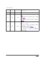
Version History:
Version
number
1.0
Date
Author
Description
2010
Mo.zhu
1.
First revision
1. Add the function of animation edit
Showed on
4.4
2.0
2011
Jf.pan
2. Add Ethernet communication setting
Showed
on 5.3.2.2
3. Add BX-4U series usual manual
Showed on
5.3.2.2
1. Add the function of self-adapt program
editing
Showed on
2. Add the function of parameters read-back
3.0
2012
Jf.pan
automatically
Showed on 5.3.1.2
3. BX-WiFi module setting
4.
Instruction
of
infrared
Showed on 7
remote
controller
Showed on 8
- 2 -
Catalogue
1. Summary........................................................................................................................5
1.1 The Summary of LedshowTW 2012................................................................. 5
1.2 Main functions & features of LedshowTW 2012............................................. 5
2. Software modify and update....................................................................................... 7
3. Interface introduction................................................................................................... 8
3.1 Menu toolbar.........................................................................................................9
3.1.1 Menu............................................................................................................ 9
3.1.2 Tool bar..................................................................................................... 15
3.2 Preview area...................................................................................................... 21
3.3 Program property area..................................................................................... 21
4. Manual details.............................................................................................................23
4.1 Screen property................................................................................................. 23
4.2 Program property...............................................................................................23
4.3 Graphic & Text property................................................................................... 25
4.3.1 Text............................................................................................................ 27
4.3.2 Subtitle...................................................................................................... 28
4.3.3 Table..........................................................................................................28
4.3.4 Up and Down........................................................................................... 30
4.3.5 Delete........................................................................................................ 30
4.3.6 Display method........................................................................................ 30
4.4 Animation property............................................................................................ 31
4.5 Dial property....................................................................................................... 32
4.6 Time property..................................................................................................... 33
4.7 Timer property....................................................................................................34
5. Common Commands.................................................................................................35
5.1 Correcting time...................................................................................................35
5.2 Brightness adjustment...................................................................................... 35
5.3 Set parameters.................................................................................................. 36
5.3.1 One-for-one mode................................................................................... 36
5.3.2 Broadcast mode.......................................................................................39
Step 1.................................................................................................................. 43
Step 3 Network server configuration............................................................ 45
Step 4 Server configuration testing.............................................................. 45
5.4 Reset screen parameter...................................................................................49
5.5 Send mode......................................................................................................... 50
5.5.1 Group send...............................................................................................50
5.5.2 Save the parameters to U disk.............................................................. 50
5.6 ON and OFF.......................................................................................................50
5.7 Time on/off..........................................................................................................51
5.8 Firmware maintenance..................................................................................... 51
6. User Manual for BX-4U series................................................................................. 53
6.1 Product Introduction.......................................................................................... 53
6.2 Technical index.................................................................................................. 53
- 3 -
6.3 Steps................................................................................................................... 54
6.4 Notice.................................................................................................................. 57
7. BX-WiFi setting........................................................................................................... 58
7.1 Summary.............................................................................................................58
7.1.1 Working mode.......................................................................................... 58
7.1.2 Setting methods.......................................................................................58
7.2 Stand-alone directly connect(AP mode)........................................................ 58
7.2.1 Setting....................................................................................................... 58
7.2.2 Customs setting....................................................................................... 59
7.3 Fixed IP (Station mode)....................................................................................61
7.4 Set in operating..................................................................................................63
7.5 Modify account 、password.............................................................................64
7.6 The relevant sets about LedshowTW 2012 software.................................. 64
8. Infrared remote controller..........................................................................................67
8.1 Using description............................................................................................... 67
9. FAQ.............................................................................................................................. 68
9.1 Computer can’t communicate with the controller......................................... 68
9.2 Unstable flashing area...................................................................................... 69
9.3 Smearing appears on the display, unstable flicker behind the display..... 70
9.4 Screen anti-color or brightness is not enough.............................................. 70
9.5 Software detail for controllers.......................................................................... 70
9.6 Screen mess...................................................................................................... 71
9.7 Notice.................................................................................................................. 71
- 4 -
Ledshow TW2012 Graphic & Text edit Software
1.
Summary
1.1
The Summary of LedshowTW 2012
Ledshow software is specially designed for LED graphic & text controller, put into the market
in 1998, after the update and development of several generations of products, the functions are
increasingly improved and easy to operate, received many appreciations from our users.
LedshowTW 2012 version is the most perfect solution since we worked on research and
development of LED asynchronous controller for so many years. It has been improved a lot in
functions and usages. Since Jan 2007, we got lots of help and guidances from the friends.
Thanks for all of you!
1.2
Main functions & features of LedshowTW 2012
Summary of Software
� Matching software for the third, fourth and fifth generation LED display controllers of
Onbon
Support controller:
� BX-3T、BX-3A1、BX-3A2、BX-3A、BX-3M、BX-4T1、BX-4T2、BX-4T3、BX-4A1、
BX-4A2、BX-4A3、BX-4AQ、BX-4A、BX-4UT、BX-4U0、BX-4U1、BX-4U2、BX4U2X、BX-4U3、BX-4M0、BX-4M1、BX-4M、BX-4MC、BX-4C、BX-4E1、BX-4E、
BX-4EL、BX-5AT、BX-5A0、BX-5A1、BX-5A1&WiFi、BX-5A2、BX-5A2&RF、BX5A2&WiFi、BX-5A3、BX-5A4、BX-5A4&RF、BX-5A4&WiFi、BX-5M1、BX-5M2、BX5M3、BX-5M4、BX-5UT、BX-5U0、BX-5U1、BX-5U2、BX-5U3、BX-5U4、BX5E1、BX-5E2、BX-5E3
Software Advantages:
� The most professional LED text controller editing software
� The most completed program management functions
� The most powerful materials editor
� The most efficient data communication
- 5 -
� The most innovative colorful magic screen frame
� The most active animation stunt selection
Cluster system management
� Group management: mostly support 256 screens
� Sending modes: group mode/save data to USB equipment
� Program edit: Program type: normal/overall situation/ real time /sharing/self-adapt
program
� Play mode: play one by one/fixed time play/timing play
� Program quantity: mostly support 192 programs
� Area quantity: mostly support 128 areas
Materials edit
� The new text editor: Support multi-languages, words spacing and lines spacing can be
adjusted
� The new table editor: Support multi-languages, powerful cell editing function
Materials supported
� Support the editing and viewing of file (txtf.)
� Support the editing and viewing of picture(*.bmp, *.jpg,)
� Support the editing and viewing of Excel and table(*.tbf)
� Support the editing and viewing of Avi and Flash animation (*.fxts *.gif, *.swf)
� Support the automatic conversion of Word and Excel
Network communication
� MAC binding machine, no need of IP, identify automatically, connect automatically
� Support PC direct connection/Ethernet connection/cross-internet connection
Clock mode
� Support multi-groups of calender and clock areas, positive and negative timing
� Support multi-groups of time zones, dials
Sensors supported
� Temperature sensors/humidity sensor/noise sensor
Languages
With new multi-languages self-adapt function keeping BX products extend to the
worldwide.....
- 6 -
2.
Software modify and update
� Add new controllers:BX5AT/5A0/5A1/5A1&WiFi/5A2/5A2&RF/5A2&WiFi/5A3/5A4/5A4&RF/5A4&WiFi/5M1/5M2
/5M3/5M4/5UT/5U0/5U1/5U2/5U3/5U4/5E2/5E3;
� Add the function of prompts (modify);
� The fifth generation controllers all support the function of continue
transferring from breakpoint (Ethernet & Serial port) which Controlling
process version is after " V120418 ". And it strengthens the effect and
reliability of wireless communication;
� All our 5
th
generation products support infrared remote control function (Except
5E series);
� LedshowTW 2012 Graphic & Text editing Software allows users canceling the limits of
clock areas (Except 4C/4E/5E series);
� Add "grouping" function (edit name) as to distinguish the controllers in many
screens;
� Add the function of import and export of broadcasting files;
� Add the function of background composition,
� Add the function of parameters read-back;
� Add the function of self-adapt program editing;
� Optimize the function of group sending;
� Add the function of program copying and pasting;
� Add WiFi controller;
� Add the function of area frame.
- 7 -
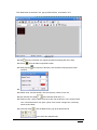
3.
Interface introduction
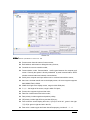
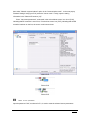
《LedshowTW2012 Graphic & Text Edit Software》 running interface is showed in figure 31,is composited by four parts.
- 8 -
Picture 3-1
3.1
Menu toolbar
3.1.1
Menu
The menu is composited with file, edit, Settings, common command, senior configuration,
send mode, language and the help. As picture 3-2
Picture 3-2
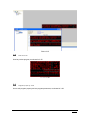
3.1.1.1 File Menu
As showed in 3-3, file menu includes: New program file, open program file, program file save
as, open program template, save program template, system backup, system restore, exit.
- 9 -
Picture 3-3
� Create program file:used to create a specified screen program broadcasting documents;
� Open program file: used to load an edit program,(prerequisite is the program has been
saved);
� Program file save as: used to save the current broadcasting files;
� Open program template;
� Save program template;
� Export broadcasting file: Save the materials. Contents of program to " Documents"
&"Project list" automatically. It is to recover the data materials when there's something
wrong with the software;
� Import broadcasting file: Import the data materials from " Documents", " Project list" to
software. Importantly, the PC software parameters should be the same with export file.
� Exist: Exit from LedshowTW 2012 Graphic & Text edit system.
3.1.1.2 Edit Menu
As showed in 3-4,the edit menu includes: add general program, add image/text zone, add
subtitle zone, add animation zone, add dial zone, add date time zone, add timer zone, delete
zone .
Picture 3-4
- 10 -
� General program:add a general program;
� Image /text zone: add a image/text area in the preview filed, prerequisite is that the
general program has been added;
� Subtitle zone: add subtitle area in the preview area, prerequisite is that the general
program has been added;
� Animation area: add animation area in the preview area, prerequisite is that the general
program has been added;
� Dial area: add dial area in the preview area, prerequisite is that the general program has
been added;
� Date time zone: add date time zone area in the preview area, prerequisite is that the
general program has been added;
� Timer zone: add timer area in the preview area, prerequisite is that the general program
has been added.
� Delete zone:Delete select object in the preview area.
3.1.1.3 Self-adapt program
Showed as picture: Self-adapt program includes self-adapt program setting, self-adapt
program editing, as to operate the program.
� Autofit _set up: could modify the parameters of graphic & text area regulations, time area
regulations, and dial area regulations;
- 11 -
� Autofit _edit: property edit by the time/dial area of the added self-adapt program, also edit
the self-adapt text by " edit message ".
3.1.1.4 Setting Menu
Showed in 3-5,setting menu includes: set screen parameters , reset screen parameters,
firmware maintenance ,network sever configuration, GPRS server configuration, Net work IP
configuration, network IP configuration, MAC address maintenance , check the screen state.
Used to set the controller parameters. More details in 5.3 set screen parameters .
- 12 -
Picture 3-5
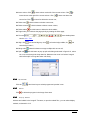
3.1.1.5 Common Commands
Showed in 3-6,common commands include: adjust brightness, correction time, automatic
correction time, turn on, turn off, timer for switch, lock screen, unlock screen.
Picture 3-6
3.1.1.6 Advanced Configuration
Showed in 3-7,advanced configuration includes: delay start screen, controller button
figuration, start LOGO configuration, sensors configuration, lock program configuration.
Picture 3-7
- 13 -
� Delay start screen: This feature is used to prevent the vehicle screen avoiding the
abnormals of the display screen by instable voltage when run the car. It can be selected
from 0 seconds to 16 seconds;
� Controller button configuration: This function applies to use manual buttons to control the
programs playing sequentially which is worked in some special occasions. According to
the different needs of users, providing three different functional configurations: test
function, edge-triggered switching program functions, level-triggered switch programs;
� Start LOGO configuration: According to the different needs of users, providing " LOGO
information displayed at startup", "When no program information is displayed, the
information display LOGO ", and could edit the height, width and hold time . LOGO file
name supports Jpg, Jpeg, bmp and other formats;
� Quantity of time area: could cancel the limites of the quantity of time area except BX4C/4E/5E;
� Sensors configuration:temperature area, humidity area, noise area;
� Lock program configuration: click the lock program box, this function will display on the
magic border of the main program.
3.1.1.7 Group Sending
Group sending menu includes: By group sending program, group timing, group ON &
OFF to operate with multi-groups and multi-screens.(The group sending function is
hided in single group and single screen.) Showed as picture 3-8.
Picture 3-8
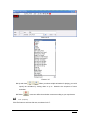
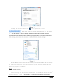
3.1.1.8 Language Menu
Click language button, open the selection list, as showed in 3-9, which used to select
software language. This software supports 14 languages, and default is English. You can select
the language as your requirement.
- 14 -
Picture 3-9
3.1.1.9 Help Menu
Click “help” menu, click the current main program of the software, the dynamic library
version and related informations,as showed in 3-10.
Picture 3-10
3.1.2
Tool bar
Tool bar showed as 3-11:
- 15 -
Picture 3-11
� Click new
:create program in current screen,as shown in 3-12:
Picture 3-12
� Open
:click the open button and select from the saved program file ,the file must be
in *.pj. Showed as 3-13.
图
Picture 3-13
- 16 -
� Save
:click the save button, pop up the “save as “ dialog, save the current program
file ,the file must be in *.pj. Showed as 3-14:
Picture 3-14
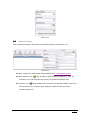
� general program
:click the program button, create a new program in the current
screen, as showed in 3-15,set the program property as your requirement. More details
about program property setting ,please check in “4.2 program property”.
Picture 3-15
� Image& text
: click the Image & text button, add new image& text area in the current
screen, as showed in 3-16,set the image &text property as your requirement. More
details about program property setting ,please check in “4.3 Images& text property”.
- 17 -
Picture 3-16
� Subtitle
:click subtitle button, add new subtitle in the current screen, as showed in 3-
17, set the subtitle property as your requirement. More details about subtitle property
setting ,please check in “4.3.2 subtitle property”.
Picture 3-17
� Animation
:click animation button, add new animation area in the current screen, as
showed in 3-18,set the animation property as your requirement. More details about
animation property setting ,please check in “4.4 animation property”.
Picture 3-18
� Dial
:click dial button, add new dial area in the current screen, as showed in 3-19,
set the dial property as your requirement. More details about dial property
setting ,please check in “4.5 dial property”.
- 18 -
Picture 3-19
� Timing
:click timing button, add new timing area in the current screen, as showed in
3-20,set the timing property as your requirement. More details about timing property
setting ,please check in “4.7 timing property”.
Picture 3-20
� Time
:click time button, add new time area in the current screen, as showed in
3-21,set the time property as your requirement. More details about time property
setting ,please check in “4.6 time property".
Picture 3-21
� Delete
: delete program and the areas in the program.
- 19 -
� Align: Select
, is area left aligned; select
aligned in the preview area; select
, is area right aligned; select
,is top
, is bottom aligned in the bottom of the preview
area.
� Brightness
:click this button could adjust the brightness of current screen, more
details pleas check in 5.2 adjust brightness.
� Correction time
� send
:more details please check in 5.1 correction time.
:click this button to send selected program to the controller.
� USB download
:click this button, install the U disk to your computer, click “save”
button. screen parameters configuration/scanning configuration/program data/correction
time/adjust brightness/timer for switch and so on will be saved in the U disk.
� Preview
:Dynamic preview , through the preview button to play, stop, turn off the
preview area of edit content and special effects, to check if the location is consistent
with the display shows, as showed in 3-22:
Picture 3-22
� Program preview
:static preview, to check that the program lists' quantity, content are
consistent with the edit preview area. Showed as 3-23:
- 20 -
Picture 3-23
3.2
Preview area
Used to preview program, as showed in 3-25:
Picture 3-25
3.3
Program property area
Use to edit program property and set program parameters, as showed in 3-26:
- 21 -
Picture 3-26
- 22 -
4.
Manual details
4.1
Screen property
Enter into the screen parameter configuration in the edit menu, add new screen and set the
parameters. Select the new screen
in the program list, screen property will be
shown in the bottom of the main interface. As showed in 4-1:
Picture 4-1
4.2
Program property
After add a new program, select the current program, set program property in the bottom of main
interface, as showed in 4-2:
Picture 4-2
� Program name: set current program name;
� Sequentially play: click this button to play program according to the program order, play
times could be set as well , maximum is 255 times;
� Time play: click this button to set the play time, maximum is 65535 seconds;
- 23 -
� Play aging: select it to set the start time and end time for the program;
� Play time: select to set detailed start time and end time for program play;
� Week property: select to set the date for program play, could also set any day of a
week,single or multiple selection is OK.
� Magic boarder: select to set the program boarder;
Select single color: click the drop down list to select board type. As showed in 4-3. Click
drop down list to select boarder color. If the screen type is single color ,only red could be
selected ,if the screen type is dual color, red/green/yellow could be selected.
Picture 4-3
Select suit: click the drop down list to select boarder type;
� Display method: click the drop down list to select the display method. As showed in 4-4:
Picture 4-4
� Move steps: click the drop down list to select move steps , maximum value is 1-8.
� Moving speed: click drop down list to select moving speed ,value is from 1-16, 1 is the
fastest, 16 is the slowest.
- 24 -
� Program background: Select and add the files with bpm,jpg,jpeg,txtf format as the
background by open and text button. Also users could edit the background stunt, run
speed and hold time according to your requirement.
4.3
Graphic & Text property
Add a new graphic & text area, select current area to set program property. As showed in
4-5.
Picture 4-5
� Name: You could set the graphic area and time zone name, enter directly.
� Location: entering the value in the XY or by clicking the mouse with up and down key to
change the XY value. You could change the frame position by dragging the frame of the
preview interface as well .
� Width and height: enter a value in the width or height or click up and down key by the
mouse to change the frame width and height values. you could change the frame
border width or height by dragging the frame of the preview interface as well.
� Open: click the button
, pop up the dialog as showed in 4-6;
- 25 -
Picture 4-6
Click files type list to open image files(*.BMP、*.JPG、*.JPEG),TXTS files(*.TXT、
*.RTF、*.TXTS)
Picture 4-7
After opening the files, open the file in preview area, open the location property of the
files in the bottom of main interface. Showed as 4-8:
Picture 4-8
- 26 -
4.3.1
Text
Click Text button, pop up text interface, as showed in 4-9. Entering text directly, and set text
font, charset, size, bold, italic, underline, color, paragraph marks, left, center, right alignment,
character spacing, line spacing, index and so on.
�
Create
�
Open
�
Save as
�
Font
�
Font charset
�
Font size
:add new text, the original will not be kept;
:Open *.TXT、*.RTF;
:keep the current text files to the specified location;
: click the drop down list to select different font;
:click the drop down list to select different charset;
: set the font size, numbers range is from 8 to 200, could select
the size from drop down list or enter size directly in the enter frame;
�
Bold
:click bold to set the select font;
�
Italic
:click italic to set the select font;
�
Underline
:click the underline to set select font;
�
Text color
:click the text color to set select font;
�
Paragraph mark
�
Left
�
Center
�
Right
�
Line spacing
�
Char spacing
�
Page index
:click this button to mark paragraph;
:click this button to set font as left align;
:click this button to set the font as center align;
:click this button to set the font as right align;
:click this button to set line spacing by moving the slider;
:click this button to set char spacing by moving the slider;
: if there's more than one pages in the file, you could see the
page quickly by locating the index page. Please enter directly to the index inputting
box or click the mouse up and down keys to fix the position;
�
Statistics: please check the total pages in the left bottom
center shows the char number
this picture
, in the
, the last is char pacing as showed in
.
- 27 -
Picture 4-9
4.3.2
Subtitle
Click subtitle button, pop up subtitle interface, as showed in 4-10 ,the button function is similar
with Text, and the difference is that subtitle can’t support CRLF.
Picture 4-10
4.3.3
Table
- 28 -
Click table button as showed in 4-8, pop up table interface, as showed in 4-11.
Picture 4-11
� New
:Create a new table, the original operation and setting will not be kept;
� Save as
:save the table to specified location.
� Table property
:set property of the table, click the button and pop up the below
interface:
�
� Header count: set table header, click the up arrow ,number is from 0-2;
� Click the table line width
, select the table width from 1-4;
� Table line color: click the down arrow to set the color of table line. if the screen is dual
color ,could select black, red, green ,yellow, if the screen is single color ,could only
select red and black;
� Cell border setup
:click the table border, pop up the drop down list
, could select the related border;
- 29 -
� Insert column: Click
to insert column at the left of the current column. Click
insert column at the right of the current column. Click
current line. Click
� Delete rows
to
to insert row above the
to insert line below the current row;
:click this button to delete current row;
� Delete columns
:click this button to delete current column;
� Delete tables:
click this button to delete the whole tables;
� Page index: you could see the page quickly by locating the index page;
� Font set:
more details please
check in 4.3.1 Text.
� Align: click
,cell vertical align top. click
,cell vertical align middle, click
,cell
vertical align bottom.\;
� Merge cells
� Split cells
:select this button to merge multiple cells as one cell;
:click this button to pop up split cells dialog as showed in figure 4-12, select
col or row cont through the drop down list. Maximum row count is 10.select “merged
cells before split” to merge the select cells firstly;
Picture 4-12
4.3.4
Up and Down
Click the
4.3.5
Delete
Click
4.3.6
up and down keys to switch program and preview in turn.
to delete the program in the Image & text area.
Display method
Add text and subtitle in the Image & Text area ,or open the related files , you can select display
method ,as showed in 4-13.
- 30 -
Picture 4-13
4.4
Animation property
Click the animation button in the menu to set animation property, as showed in 4-14.
Picture4-14
� Name, location(XY), width, height setting please check 4.3 Images&text property;
� Open animation: click
, pop up dialog to select animation, support Avi、Fxts、Gif
and Flash. You could define the play frames, play speed and residence time;
� Animation: click
,Calling software built-in format as. fxts animation effects, users could
also edit the font size, character name, alignment, caption content, and select
animation effects, etc.
- 31 -
Picture 4-15
Picture 4-16
� Up and down
:When you select multiple animation for playing, you could
specify the animation by moving down or up to
determine the sequence of some
animation;
� Delete
4.5
: users can define the animation content according to your requirement.
Dial property
Click Dial button to add new dial area, as showed in 4-17.
- 32 -
Picture 4-17
� Name ,XY, width ,height setting, please check 4.3 Image& text.
� Display: users could select the static text ,Y/M/D, week by single or multiple selection.
Corresponding content will be displayed in the dial area. Users could also select the
Y/M/D mode by clicking the drop down list.
� Time difference : more details please check 4.6 time property .
� Font setting: users can select the setted font by “unit type”, click the dropdown list to
select static text ,Y/M/D, week. More font setting ,please check 4.3.1 Text .
� Automatic adjustment
: click this button to adjust the location of “static text”, adjust up,
down ,left ,right by
.
� 3.6.9 property: click the drop down list to select the type, size and color.
� Hour point: similar as 3.6.9 property.
� Minute point: similar as 3.6.9 property.
� Hour hand : click the drop down list to select the hour hand size and color.
� Minute hand: similar as hour hand.
� Second hand: similar as hour hand.
4.6
Time property
Click the time button in the tool menu, add time area and set the property. As showed in 4-18.
Picture 4-18
- 33 -
� Name ,XY, width, height and so on, more details please check 4.3 Image&text property;
� Display: could select single line or multi-line;
� Font size: select “static text” and set the font. Users could set the font size ,align and so
on. If the screen type is dual, could select red, green, yellow ,if the screen type is single ,
then could only select red. More details please check 4.3.1 text;
� Static text: you could edit text according to the different requirement from customers( in
20 words);
� Time difference: you could set negative or positive time by selecting the drop down list,
the hour difference range is from 0-23, the minute difference range is from 0-59;
� Display effect: Could select the effect of the preview display, as showed in 4-19. At
least choose one, such as the display, if do not choose, the content will be not
displayed, also could choose the text color.
Picture 4-19
4.7
Timer property
Click the timer button in the tool bar, add new timer area ,as showed in 4-20, more details, please
check 4.6 timer property.
Picture 4-20
- 34 -
5.
Common Commands
5.1
Correcting time
Click the manual
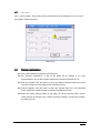
5.2
, automatically correct the time with controller chip.
Brightness adjustment
Click the adjust brightness button
:pop up the dialog as showed in 5-1,could set the screen
brightness at different time.
Picture 5-1
Brightness adjustment includes manual and timer adjustment.
Manual adjustment could set the brightness value by manual, and send the value directly.
Timer adjustment could supply four time segments, only selected, it could work. Showed as
5-2:
- 35 -
q
Picture 5-2
5.3
Set parameters
5.3.1
One-for-one mode
�
Set screen parameters: as to set the controller parameters.
�
Click “set screen parameters” enter “168”. Showed as 5-3. Popping up the set
parameters dialog, as showed in 5-4. This setting is one-for-one mode, which is
only effective to current screen. On this mode, modify one of the screen will not
effect other serial screen parameters.
Picture 5-3
- 36 -
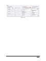
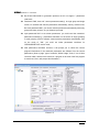
Picture 5-4
5.3.1.1 Screen parameters selection tab
�
Screen name: show the name of current screen;
�
Build address: add remark to distinguish many screens;
�
Controller: the screen controller model;
�
Communication mode: Communication media types between the computer and
screen. Currently the system is directly embedded by serial communication, GPRS
wireless communication and network communication;
�
Serial ports: computer serial port will be used to communicate with the screen;
�
baud rate : the data transfer rate to the display screen, the current system supports
9600,28800,57600,115200;
�
Width: the length of the display screen ,range is within 4096 pixel;
�
Height: the height of the screen, range is within 512 pixel;
�
Screen color: support single and dual color;
�
Date flow: include normal and mirror mode;
�
Date polarity: include negative and positive polarity;
�
OE polarity: include high efficiency and low efficiency ;
�
Pixel: when the screen display dual color, I (R+G) is red in left , green in the right.
Ⅱ(G +R)is green in right and red in the left;
�
Row order: it means upper and lower data offset property, includes 0、-1、+1.
- 37 -
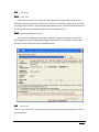
5.3.1.2 Parameters read-back
�
BX-3T/3A1/3A2/3A/3M 3rd generation products are all not support " parameters
read-back";
�
Passwords "888", then edit " screen parameters setting". In single group and single
screen, PC software will read the parameters automatically, also by manual is OK;
But with passwords"888", you cannot read the parameters automatically with many
groups and many screens, so, you'd better by manual.
�
Input passwords"168" to set screen parameters, you could read the controllers'
parameters manually by " parameters read-back" on the screen of single grouping
or multi grouping. And PC software cannot read the parameters automatically, also
on the mode of "168", you could not select parameters read-back on
GPRS/USB/NET/WiFi server mode;
�
After parameters read-back succeed, it will prompt you to cancel the current
program informations if the read-back parameters are different from the current
parameters. (How to judge: type of controller, Width, Height, Color, if one of them
could not match, and there are more than 1 program or the area of the first program
is more than 0, then, will prompt this information.)
Picture 5-5
- 38 -
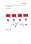
5.3.2
Broadcast mode
Click “set screen parameters
” to the pop up dialog( as show
ed in 5-3)click
parameters”” enter “888
888”
showed
” to pop up the “set screen parameters
” dialog as show
ed in 5-5 ,this is a broadcast
“OK
OK”
parameters”
showed
mode setting.
Notice:1. In this mode, the loading screen parameters / scan configuration / parameter
read-back, the computer serial port could only connect one screen
screen!! Otherwise, all will be
modified to display the same parameters
parameters..
Choose the "Main Menu displays advanced configuration functions", "Advanced
2.C
Features" button will appear in the software menu bar, it will not be displayed if you did
not choose
choose..
Picture 5-6
5.3.2.1 Scan configuration
Users can select 1/16、1/8、1/4、1/2 scanning mode.
Click write parameters button to pop up the following information:
- 39 -
Picture 5-7
After the successful loading of the system , click scanning mode , select scanning mode in
the list.
Manual configuration: set the scanning mode by manual operation.
Automatic detection: interval will be 3-20 seconds, click start, then, automatic detection. The
system will select scanning mode according to the scanning time. Please check all kinds of the
scanning mode to select the scanning mode as your requirement.
5.3.2.2 Network Communication Setting
BX-4M series, BX-4E series support Ethernet(RJ45 interface), LED screen could update the
program by TCP/IP. The work modes include PC direct connection, static IP and network server
mode.
5.3.2.2.1
PC direct link mode
PC direct link is mainly used for single display applications in simple network environment.
On this mode, directly connect BX controller with computer by network cable .Open "Ledshow
TW2012",select "setup"-"set screen parameters "(as showed in 5-9) select "network
communication" in "communication mode" option, select "network settings" in the " direct link"
option( as showed in 5-10),you could send data by BX controller without other setting.
Picture 5-8
- 40 -
Picture 5-9
5.3.2.2.2
Fixed IP Mode
Fixed IP mode used in the environment of LAN or simultaneously control multiple display.
Before using fixed IP mode ,users need set the IP information to BX controller.
Opened software "LedshowTW 2012", select "Setup" - " set screen parameters" , select the
current controller model, then select "Network Communications" in the "communication mode" .
Turn off "set screen parameters " .
In the main menu, select "Setup" - "Network IP Configuration" module (5-11). In this module,
set the IP information to the BX controller.
Picture 5-10
- 41 -
You need to connect the BX controller with PC direct link mode by "Network IP configuration".
Enter the "Network IP Configuration", select "Fixed IP Mode", edit the parameters in the dialog
box. Click "setup" to set the BX controller parameters. Then record the related IP information of
BX controller. if parameters setting is successful, the BX controller could be connected to LAN
control.
After connected with the LAN, open the software" LedshowTW 2012 "in a computer which
has accessed to the LAN. In the main menu, select "Setup" - "set screen parameters " , add a
corresponding screen, select current BX controller model, and then select "Network
communications" in "communication mode" in .In the new pop-up "Network Settings" tab (5-12),
select "Fixed IP Mode." Finally, edit the relevant informations in the "Controller IP Settings", the
controller communication will be OK.
Picture 5-11
5.3.2.2.3
Network server mode
Network server mode is commonly used in cross-Internet network environment, in this mode,
only the server has a fixed IP address, and BX controller could access any network interface to
visit the Internet, the server could control BX controller (5-12).
- 42 -
Picture 5-12
Before using network server mode, users need to do port mapping and set the IP information
for BX controller in the software "LedshowTW 2012".
Notice: blue font in the following is operation cases parameters.
Step 1
Server port mapping setting :enter into the router setting by IE browser. In the IE address
bar, input the LAN gateway to enter into the router settings. Entering the default gateway in the IE
address bar, it will pop-up window (5-13), enter a user name and password: admin/admin.
Picture 5-13
If the router needs a password, enter a user name and password into the router settings
page (5-14), setting port mapping in the router's virtual server , if your local computer IP is
192.168.0.105 (as the picture showed), activate assigned port 5005 , execution can be saved.
And please note the network's IP address of the router configuration in the Internet network, (for
example: "222.64.228.204"), and the assigned port information (5005).
There are many models of the router, and with different setting method. You could
check from the website.
- 43 -
Picture 5-14
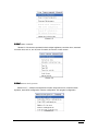
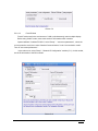
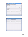
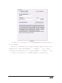
Step 2 the server IP configuration
Open Local Area Connection Properties in the computer network adapter setting, doubleclick "TCP / IP protocol" (5-15). Then select and use the following IP address to set(5-16). (Don't
select automatically obtain)
Picture 5-15
- 44 -
Picture 5-16
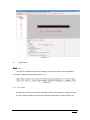
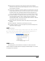
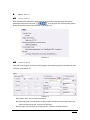
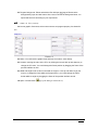
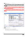
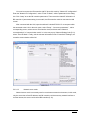
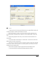
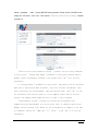
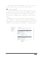
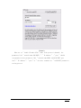
Step 3 Network server configuration
Open “LedshowTW 2012” in the server port. Select “setup”-“network server
configuration”(figure 5-17)
Picture 5-17
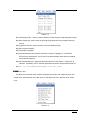
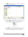
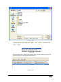
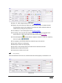
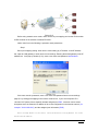
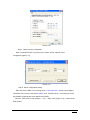
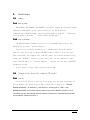
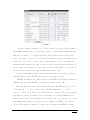
Step 4 Server configuration testing
Enter the Server LAN IP in the running server, ("192.168.0.105"), enter the port mapping
information of the server to the edit box (5005), click "Start the server", if the setting is correct,
the software will prompt the server started successfully.
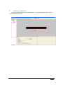
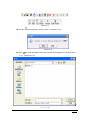
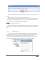
From the "Start" menu of the computer → "run" →input "cmd" (Figure 5-18)→ enter into the
DOS window.
- 45 -
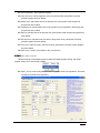
Picture 5-18
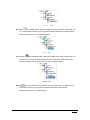
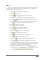
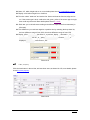
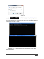
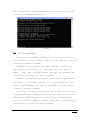
Enter
in the DOS window (figure 5-19), 222.64.228.204 is the
WAN IP. 5005 is a local IP port assigned in the router, telnet is test command, press Enter, if the
server builds a successful map, it will show like 5-20. Then, the server port mapping, LedshowTW
2012 software configuration is complete.
Picture 5-19
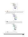
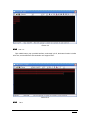
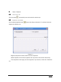
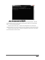
Picture 5-20
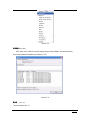
If appears like "5-22", In that case, the server fails to start, please make sure the network
state is well after reset.
- 46 -
Picture 5-21
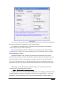
Step 5 BX controller network IP configuration
Open software "LedshowTW 2011", select "Setup" - " set screen parameters" , select the
current controller model, then select "Network Communications" option in the "communication
mode" . Turn off "set screen parameters ".
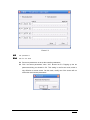
In the main menu, select :setup”→“network server configuration"(5-17) ,enter the port
mapping information in the server IP and editor box ,after entering them, please close this module.
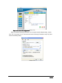
In the main menu, select "Setup" - "Network IP Configuration" module (5-22). In this module,
set the IP information to the BX controller.
- 47 -
Picture 5-22
You need to connect the BX controller with PC direct link mode by "Network IP configuration".
Enter into the "Network IP Configuration", select "Fixed IP Mode".
In the dialog box, the display screen IP information is the information of LAN for the BX
controller, well, users don't need to set the port.
Server IP information field, "Server IP Address" is the IP address in the Internet network
("222.64.228.204"). "Server Port" must be the same as the "port" parameter (5005) in "network
server configuration" window!
Heartbeat information is the connecting information which send when the BX controller
connects with the network, and then connect with the server automatically. "Heartbeat interval" is
the interval for BX controller to send heartbeat messages to the server. "Network ID number
(12)" is the unique identifier code for BX controller and the server to identity BX controller, also
note that the number in the same system can not be repeated. User could customize the code.
After setting, click the "Setup" button. Parameter setting is successful, connect the BX
controller to the corresponding terminal network..
Step 6 BX controller connection testing
After BX controller connected with the network, open the server software "LedshowTW 2012".
And after started the web server successfully, in the main menu, select "Settings" - " set screen
parameters", add a corresponding screen, select the corresponding BX controller model, and
- 48 -
then select "Network communications" option in the "communication mode" . In the new pop-up
"Network Settings" tab (Figure 5-23) select the "server mode." Finally, input the setting
information in the "Network ID number (12)".
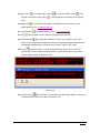
Close "set screen parameters", as showed in the main window screen. Icon is red (5-24),
indicating that BX controller is not on-line, if it's the blue screen icon (5-25), indicating that the BX
controller has been on the line, the screen could communicate.
Picture 5-23
Picture 5-24
Picture 5-25
5.4
Reset screen parameter
Input the password "168", as showed in 5-3, is used to reset the selected screen parameters.
- 49 -
5.5
Send mode
5.5.1
Group send
Click the menu "Send” or "Group send", after selected the sending mode, all the screen
information will be showed in the cluster list. All check box is selected by default ,when the user is
not ready to send a screen, click the corresponding display screen, cancel the selected check box,
you could send all the commands except "set screen parameters" in turn.
5.5.2
Save the parameters to U disk
Click “save the configuration to the U disk“, install the U disk to the computer, click SAVE.
Screen parameters /scan configuration/brightness adjustment/ timer for switch /correction time
and so on, will be saved in the U disk. As showed below:
5.6
ON and OFF
Click “turn on “ and “turn off”, users could open the connected screen by automatic turn on or turn
off the software.
- 50 -
5.7
Time on/off
Click “Timer for switch", users could open the connected screen by automatic turn on or turn off
the software. Showed as below:
Picture 5-26
5.8
Firmware maintenance
� Users could maintain the controller by this firmware.
� Click “firmware maintenance“ to pop up the dialog box as showed in 5-3, input
password”888” to pop up the firmware maintenance interface as showed in 5-27.
� Check the firmware: click this button to check the related information about the current
controller firmware, the information will be showed in the box.
� Firmware upgrade: click this button to select the upgrade REL files. Click download
button, finally click activation button to activate the download firmware.
� Restore the factory settings: switch to this page, the current firmware name, version,
modify time will be showed. Click “restore the factory settings“ to restore the firmware.
As showed in 5-28.
- 51 -
Picture 5-27
Picture 5-28
- 52 -
6.
User Manual for BX-4U series
6.1
Product Introduction
BX-4U is USB series controller, no need of serial port, operating easier; Screen parameters
setting/Scan configuration/program updating/correction time/adjust brightness/time on/off are
finished by downloading to U disk; Meanwhile, it supports updating firmware by U disk and
temperature sensor. BX-4U series products support wide working voltage with best techniques
and quality.
Connect the U disk, which has programs in there, with the USB interface of the controller(or
USB extension cable interface), programs will be uploaded automatically to the FLASH memory,
update and cover the original programs. After upload programs successfully, Led display screen
will be in the updated programs status, now you should unplug the U disk.
6.2
Technical index
Technical index for BX-4U series U disk controller
Model
Control
area
Single
Display
Display mode
Area/Program
interface
512*16 256*32
color 8K
1 nos T8 & 2
8
areas,
BX-
dots
nos T12
programs
4UT
Dual
128
256*16 128*32
color 4K
dots
Single
8
1024*16 512*32 320*48 256*64
color 16K
BX-
dots
4U0
Dual
areas,
128
programs
512*16 256*32 160*48 128*64
color 8K
dots
Single
2
1536*16 768*32 512*48 384*64
color 24K
BX-
dots
4U1
Dual
nos
4nos T12
T8
&
8
areas,
128
programs
768*16 384*32 256*48 192*64
color 12K
dots
- 53 -
Single
4
3072*16 2048*32 1344*48 1024*64
color 64K
BX-
dots
4U2
Dual
areas,
32
programs
1536*16 1024*32 672*48 512*64
color 32K
dots
Single
3200*16
color 96K
1280*80 1024*96 896*112 768*128
BX-
dots
4U2X
Dual
color
2560*16
64
2400*32
2048*32
2048*48
1344*48
1536*64
1024*64
896*80 768*96 640*112 512*128
K dots
1
3200*16
Single
color
96
K dots
2048*48
1536*64
interface
1280*80 1024*96 896*112 768*128
HUB128-
704*144
T8/T12
640*160
576*176
512*192
50PIN
with
32
areas,
192
programs
480*208 448*224 416*240 384*256
BX4U3
2400*32
nos
Dual
color 64K
dots
2560*16
2048*32
1344*48
1024*64
896*80 768*96 640*112 512*128
448*144
384*160
352*176
320*192
288*208 288*224 256*240 256*256
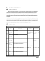
6.3
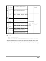
Steps
Step 1, set screen parameters.
Notice: When you select BX-4U0/4U1/4U2/4U3/4UT controllers, the original “Write screen
parameters" button is instead by the "Save" button. Selecting the appropriate controller model
and the corresponding parameters setting, click the "Save as" button, the screen parameters
information will be saved in the computer, but not loaded into the LED controller immediately(6-1).
- 54 -
Picture 6-1
Step 2
Scanning configuration
If your display driver circuit is one of the most common types, please use quick scan
configuration module to complete the scan configuration. Otherwise, please enter into the scan
configuration module, select the right scanning method, click the "Save as" button, then scan
configuration information will be saved in the computer, but not loaded into the LED controller
immediately.
Step 3
Edit program
This step is similar to the other controller model.
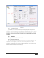
Step 4 Save all the data to U disk.
After edited the program, click "USB download" button, pop-up software dialog box. Then
insert U disk into the computer, click the "Save " button. Screen parameters set / scan
configuration / program data / time correction / brightness adjustment / timer switch and other
data will be saved immediately into the U disk. (6-2)
- 55 -
Picture 6-2
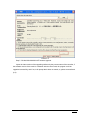
Step 5 BX-4U0/4U1/4U2/4U3/4UT firmware upgrade.
Import the latest version of the upgrading software by the process name of the controller, if
the software version of the model is consistent with the control card, the program could be
upgraded successfully, and if not, it will prompt that it does not match, so, please re-transferred.
(6-3)
- 56 -
Picture 6-3
Notice
6.4
1. Programs save into the U disk by the USB shortcut key in LedshowTW2012 interface. Do
not make any change to “onbonbx” file and folder in the U disk.
2.When save programs to U disk, you must ensure that the controller parameters is as
same as the setting in LedshowTW 2012. Otherwise, it can not update program, it says "data
error."
3. Before saving programs to the U disk, you must ensure the U disk formatted: FAT or
FAT32 format.
4. If the screen shows "unknown device" or "unknown disk", users need to re-check if the
USB connection is loosed or re-plug U disk.
5. Each time you re-plug U disk controller or restart the controller, program will be uploaded
automatically. Therefore, after the program is successfully uploaded, you should pull out U-disk
promptly as to prevent repeat upload.
6. Each U disk only supports saving one program with same sized display screen.
7. If U disk shows abnormal, please proofread display parameters carefully.
- 57 -
7.
BX-WiFi setting
7.1
Summary
7.1.1
Working mode
BX-5A1&WiFi、BX-5A2&WiFi、BX-5A4&WiFi controllers support the playing programs
updating of LED display screen, which realized by the TCP/IP protocol
communication of BX-WIFI module. And the working modes include two: " Stand-alone
directly connect (AP mode) "、" Stable IP(Station/STA mode) ".
7.1.2
Setting methods
The BX-WIFI module parameters are not set on LedshowTW 2012 software, but
manually set by using " Internet Explorer ".
You'd better set the IP information to " Automatically obtain IP address "
when it's your first time to operate BX-WIFI module or when it is on the reset
mode status.Then, the computer will find and connect the wireless network firstly
which with " BX-WIFI " character string. After that, you are supposed to input "
http://192.168.100.1" in " Internet Explorer ", then get into the page of BX-WIFI
parameters setting.
Notice: Default account: admin; Default password: 888.
7.2
Stand-alone directly connect(AP mode)
7.2.1
Setting
Users could use operate it directly if you do not have any other requirement for
setting BX-WiFi. The default wireless WiFi network name for BX-WiFi is " BX-WiFiB045031206190037 ", IP address is: " 192.168.100.1", sending port is: " 5005 ". And "
B045031206190037" is the unique factory number on the back of BX-WiFi controller. The IP
information sets as " automatically obtain IP address", DNS sets as " automatically obtain DNS
server address". Showed as picture 1:
- 58 -
Picture 1
Clicking the wireless network icon
, pop-up (picture 2), select
. After that, check the current network status, if the status
is " 192.168.100.XXX ", then, it's working. At that time, the BX-WiFi controller could get
communication with LedshowTW 2012 software by wireless network. The relative LedshowTW
2012 settings, please check from the below " LedshowTW2012 software settings".
Picture 2
On this method, users did not do any setting, and wireless module did not encrypt,
so, other users could also visit this controller by this wireless network name and
modify any properties of BX-WiFi.
7.2.2
Customs setting
Users could also set the encrypted informations, IP informations and so on. Open "
Internet Explorer ", input " 192.168.100.1 ", get into the login interface, input account"
- 59 -
admin ", password:“888”, get into BX-WiFi setting interface. Firstly, set the " BX-WiFi mode
setting" as " AP mode ", click " OK ". Then, select " wireless access point settings ", showed
as picture 3:
Picture 3
" Wireless access point parameters setting " is mainly for the setting of BX-WiFi
as access point. " network name (SSID) " parameters is the wireless network name of
BX-WiFi. Others could modify according to the system. Click " OK " as to save the
information.
If " Encrypted mode " set BX-WiFi as access point, then connect with the encrypted
mode. But if the encrypted mode is Disable, every user could get into BX-WiFi. Then,
users could select one encrypted mode, input the relevant words, click " OK " to save
the information. This function works as: if the computer connect WiFi by wireless
network, the computer would prompt the users to input a correct password.
" LAN parameters setting " is mainly for setting the IP information and
communication port when BX-WiFi is as access point. Then, if computer connects with
BX-WiFi wireless network, users should set the IP information of computer as the same
as in BX-WiFi. And set the " DHCP type " as " server ". Click " OK " as to save the
information.
- 60 -
After setting done, click " BX-WiFi management", click " restart ". Then, waiting
for about 1 minute, reconnect the wireless network. Setting as capture 7.2.1.
7.3
Fixed IP (Station mode)
Stable IP mode usually used in LAN or with one more display screens. Under
this condition, you need to install a wireless router, BX-WIFI will connect with
the wireless router automatically. Then, the computer gets into network by
wireless router, as to communicate. Note: you must install a wireless router for
BX-WIFI.
When BX-WIFI is on the factory initial status, open " Internet Explorer "→
input " 192.168.100.1 " on the address→ enter into login page of wireless module
→ input default account " admin ", default command " 888 " → enter into set page
of BX-WIFI → enter into the page " wireless terminal set ". Showed as picture 4:
Picture 4
- 61 -
Picture 5
" wireless terminal parameters set " mainly used to set the relevant parameter
when BX-WIFI module connects into wireless router. " Network name (SSID) which BXWIFI gets to connect " is the name you will connect with wireless router. Also,
users could click " search " as to find out the present wireless network(showed as
picture 5), click " OK ", you will be in. And meanwhile, it will correspond the
encryption mode automatically, but if the wireless network has been encrypted, you
need to input the passwords as to get into; if there's MAC address filter limit in
wireless router, you need to input the MAC codes. Click " OK ".
If there's MAC address filter limit in wireless router, you need to join into
this MAC address. Then, BX-WIFI would connect into wireless router.
" BX-WIFI IP address set " mainly used to set BX-WIFI IP informations and data
communication port when BX-WIFI is in wireless network. Click " OK ".
After the above two steps, entering into the page " BX-WIFI mode set ". Click
" Station mode " → " OK " → enter into " BX-WIFI management "
restart ".
Then, close the present setting process,
→ click "
connect with wireless router,
and input the correct IP address. After one minute, the restarted BX-WIFI will
connect with wireless router automatically. At that time, you 'd better try to use
Ping command Ping module in the system, the IP address of BX-WIFI. And if Ping
succeed (like picture 6 showed), it means that the computer and BX-WIFI connect
- 62 -
well by wireless router. About LedshowTW 2012 software set, please set according
to the below " LedshowTW 2012 software set ".
Picture 6
7.4
Set in operating
If you need to reset BX-WIFI in operating process, you could set directly by "
Internet Explorer ", whatever the mode of module is at that time, only if you know
the present set parameters of module.
If BX-WIFI is in Stand-alone directly connect (AP mode), you only need to
input IP address in " IP address " of " LAN parameters set " in " Internet
Explorer ", then, connect into BX-WIFI module. After that, you could modify the
relevant property according to the above set methods.
If BX-WIFI is in Stable IP (Station mode), you only need to input IP address
in " IP address " of " BX-WIFI IP address set " in " Internet Explorer ", then,
connect into BX-WIFI module. After that, you could modify the relevant property
according to the above set methods.
If you forget the original setting property, but also want to reset, you need
to press on RST button on BX-WIFI controller about 10 seconds as to recover. And
about one minute, BX-WIFI module will restore the factory settings,then, the
wireless network name of BX-WIFI is " BX-WIFI ". After that, you could modify the
relevant property according to the above set methods.
- 63 -
7.5
Modify account 、password
If you want to modify BX-WIFI account 、command, you could modify the account
and login command in " managers set " of " BX-WIFI management " after login BXWIFI in " Internet Explorer ". Then, click " restart ".
7.6
The relevant sets about LedshowTW 2012 software
After BX-WIFI module set done, you need to do some relevant sets to the
corresponding controller property of LedshowTW 2012 software before updating the
display informations of BX-WIFI controller.
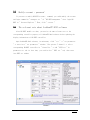
Open LedshowTW 2012 software, in main menu, click " set " → " set parameters
" → enter into " set parameters " window ( like picture 7 showed ) → select
corresponding BX-WIFI controller in " Controller " → add " WIFI set " in
parameters set tab. At that time, you could select " WIFI set " tab, then enter
into WIFI set window.
Picture 7
- 64 -
Picture 8
In " WIFI set ", you could select the corresponding mode according to what you
have set in WIFI.
When set as " Stand-alone directly connect (AP mode),showed as picture 8, the
parameters like " network name (BX-WIFI) "、" IP address " 、" port " should
correspond with the parameters like " network name(SSID) "、" IP address "、" port
" of " wireless access point set " in BX-WIFI parameters setting process.
- 65 -
Picture 9
When set as " Stable IP mode (STA) " mode (like picture 9 showed), the
parameters like " network name (BX-WIFI) "、" IP address " 、" port " should
correspond with the parameters like " network name(SSID) which BX-WIFI gets
into"、" IP address "、" port " of " wireless terminal set " in BX-WIFI parameters
setting process.
- 66 -
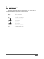
8.
Infrared remote controller
8.1
Using description
The maximum communication distance is 8 meters, angle is ±45°. (Notice: There are 2
seconds for delay when you select program.) Functions of the keys:
� Power
ON/OFF
� MENU
unlock the program
� TEST
testing mode
� +
increase the brightness
�
close the testing mode
�
last program
�
play/stop
�
next program
� -
decrease the brightness
� 0~9
1~128 lock program 1-128
- 67 -
9.
FAQ
9.1
Computer can’t communicate with the controller
� Please check if the communication line (or cable, or GPRS connection cable) of your
computer and control card is connected properly.
� Check the control card to see whether the using controller is corresponding with the
selected control components on the software.
� Check whether the computer's serial port is corresponding with the serial port settings
on the software.
� Check the jumper cap on the control card to see if it is the selected jumper cap of
232/485 in communication mode.
� Please check if the selected communication mode is corresponding with the software
setting, such as 232/485 communication mode, network communication or GPRS
communication。
� Test the controller with shorter distance of the computer, or change a lower baud rate for
testing.
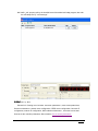
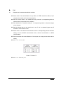
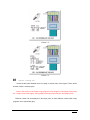
� Details for serial port
Picture 7-1 Picture 7-1
� Details for Ethernet port
- 68 -
Picture 7-2
Picture 7-3
9.2
Unstable flashing area
Please double-check whether there is overlap in various parts of the region, Flicker will be
showed if there is overlap region.
Notice: each screen could support many programs, each program could support many areas,
like: Graphic area could support many graphics (including many text files and graphic files).
Different content can be displayed in the same place or show different content when many
programs are in sequentially play.
- 69 -
9.3
Smearing appears on the display, unstable flicker behind the display
When smearing or unstable flicker
appears on the display, please modify the scanning
frequency or frequency factor in “set screen parameters” and decrease the default value, so the
signal could spread longer and further.
9.4
Screen anti-color or brightness is not enough
More details please check 5.3 “set screen parameters”.
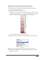
9.5
Software detail for controllers
Common Software
Name
Release date
Controller model
LedshowTW 2010 Graphics & text edit
2010-07-14
BX-3T/BX-3A1/BX-3A2/BX-3A/BX-
software
3M/BX-3E
LedshowTW Super Graphics & text edit
2009-11-23
BX-E/BX-CⅡ/CⅡ+/MⅡ/A/TⅡ
2009-10-19
BX-E/BX-CⅡ/CⅡ+/MⅡ/A/TⅡ
2009-9-30
BX-E/BX-CⅡ/CⅡ+/MⅡ/A/TⅡ
2009-9-21
BX-E/BX-CⅡ/CⅡ+/MⅡ/A/TⅡ
software V3.0
LedshowTW Super Graphics & text edit
software V3.0
LedshowTW Super Graphics & text edit
software V3.0
LedshowTW Super Graphics & text edit
software V3.0
LedshowZM stage caption edit software
BX-Z
v3.10.01.20
LedshowTW
Graphics
&
text
edit
BX-S16/S16F/S16FE/SC
softwareV4.92
Customized Software
Name
Release date
Ledshow Bank lintel cluster information
release system KAV
Controller model
BX-E
V2.8
Ledshow lintel cluster information release
2009-05-01
BX-GPRS&BX-E/CⅡ/MⅡ/TⅡ
system V1.0
LedshowGG Media edit release system
BX-GPRS&BX-QⅡ/QTⅡ
Network version V1.0
LedshowHR
Talent
market
cluster
2008-10-18
BX-A/T/AⅡ/TⅡ
- 70 -
information release system V3.2
LedshowGJ Traffic advertisement edit
release system V1.0
BX-GPRS、 BX-QⅡ/QTⅡ
Notice: please select the matched software to each controller, or the communication will fail.
9.6
Screen mess
� Please check if your controller power is well (Test if the power could offer enough to the
display panel and controller ).
� Check if the supply power shares a same grand with others ( is 5V direct current, do not
mixed).
� Please check that the the connection of controller,HUB board and display screen
is correct.
9.7
Notice
� Please note that make anti-static treatment, or check if the zero line or ground handling is
good, users should not plug or unplug the serial port, or they may burn the computer's
serial port or controller. If you need do this, please turn off the computer or the screen
power and then plug the serial cable. If you frequently burn communications chip or
burn multiple communication chips, you should double-check the communication line.
� Please do not use electric iron to maintain controller by yourself, or please do all kinds of
protection in the case of bad environment, including water, dust, corrosion and other
aspects, or they may cause that the controller could not be repaired, or even scrapped.
- 71 -