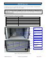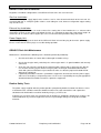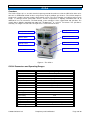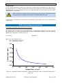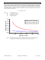
1
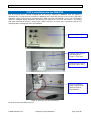
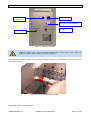
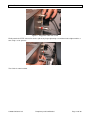
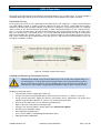
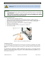
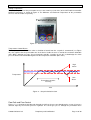
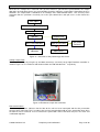
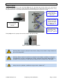
OWL-GEN-SYS-4-UM v1.5
24/06/08
GEN-SYS User Manual
© 2008 Owlstone Ltd
Proprietary and Confidential
Page 1 of 20
OWL-GEN-SYS-4-UM v1.5
24/06/08
About this Manual
This user manual contains all the information you will need to initially install and run the Owlstone GEN-SYS
system. Additional information and updates are available on the Owlstonenanotech.com website under the
support tag.
It is essential that this user manual be read and understood before commencing any work with
the system. Read and understand the various precautionary notes, signs, and symbols
contained inside this manual pertaining to the safe use and operation of this product before
using the device. Using the GEN-SYS in a way that is not specified in this manual could be
harmful to health of the operator and co-workers.
This symbol is used to highlight a section explaining particularly important safety considerations
Contents
NOTICES .............................................................. 3
GEN-SYS RACK UNIT ........................................ 7
Copyright ............................................................. 3
GEN-SYS Parameters and operating ranges .. 7
Disclaimer............................................................ 3
Notice of Proper Use of Owlstone Ltd
Instruments ......................................................... 3
GEN-SYS Rack Unit Installation ....................... 8
Gas line Installation .......................................... 8
Exhaust line Installation.................................... 8
Power Supply Unit ............................................ 8
Contacting Owlstone.......................................... 3
GEN-SYS Rack Unit Maintenance .................... 8
Recycling and Disposal ..................................... 3
Routine Safety Tests ......................................... 8
Certificate of Conformity ................................... 4
OVG-4 .................................................................. 9
INTRODUCTION .................................................. 5
Overview ............................................................. 9
Overview .............................................................. 5
OVG-4 Parameters and Operating Ranges...... 9
Harmful substances ........................................... 5
PRE-INSTALLATION GUIDE .............................. 5
Location ............................................................... 5
Power ................................................................... 5
Gas supply .......................................................... 6
OVG-4 INSTALLATION INTO THE GEN-SYS . 10
OVG-4 OPERATION ......................................... 13
Permeation Device ......................................... 13
Loading and Removing Permeation Devices . 13
Temperature Control ...................................... 14
Flow Path and Flow Control ........................... 15
Sample outlet ................................................. 18
Exhaust ................................................................ 6
OVG-4 CALCULATING CONCENTRATIONS.. 18
Analyte(s) ............................................................ 6
OVG-4 MAINTENANCE .................................... 20
General Installation safety requirements ......... 6
OVG-4 TROUBLESHOOTING .......................... 20
© 2008 Owlstone Ltd
Proprietary and Confidential
Page 2 of 20
OWL-GEN-SYS-4-UM v1.5
24/06/08
Notices
Copyright
©2008 Owlstone Ltd. All rights reserved. Owlstone Ltd provides this user manual to its customers to use in
the Product operation. This manual is copyright protected and no part of this publication may be reproduced,
transmitted, transcribed, stored in a retrieval system or translated into any language or computer language,
in any form or by any means, without the prior written permission of Owlstone Ltd.
Swagelok® is a registered trademark of Swagelok Company.
Disclaimer
Owlstone Ltd makes no representations or warranties, either expressed or implied, with respect to the
contents hereof and specifically disclaims any warranties, merchantability or fitness for any particular
purpose. Furthermore, Owlstone Ltd reserves the right to revise this publication and to make changes from
time to time in the contents hereof without obligation of Owlstone Ltd to notify any person of such revision or
changes.
Notice of Proper Use of Owlstone Ltd Instruments
The supplied system is in compliance with international regulations. If this system is used in a manner not
specified by Owlstone Ltd, the protection provided by the system could be impaired
Contacting Owlstone
Visit the Owlstone website (www.owlstonenanotech.com) for up to date contact details and service support:
For general inquires please email [email protected]
UK Office:
St Johns Innovation Centre
Cowley Road
Cambridge
CB4 0WS
Tel: +44(0)1223 422415
Fax: +44(0)1223 422414
US Office:
Park 80 West
Plaza II
Saddle Brook
NJ 07663
Tel: +12028804882
Fax: +1 201 8804894
Recycling and Disposal
This Product has been designed and manufactured with high quality
materials and components, which can be recycled and reused.
This product is required to comply with the European Union's Waste
Electrical & Electronic Equipment (WEEE) Directive 2002/96/EC so should
not be disposed of in normal waste. In some locations the radioactive
source has additional disposal requirements; please consult Owlstone Ltd for
details of our recycling and disposal program for this product.
For users outside the European Union consult local authorities for correct
disposal or contact Owlstone Ltd.
© 2008 Owlstone Ltd
Proprietary and Confidential
Page 3 of 20
OWL-GEN-SYS-4-UM v1.5
24/06/08
Certificate of Conformity
Owlstone Ltd performs complete testing and evaluation of its products to ensure full compliance with
applicable domestic and international regulations. When the system is delivered to you, it meets all relevant
electromagnetic compatibility (EMC) and safety standards as described in the declaration below.
Owlstone Ltd declares under its responsibility that the electronic product GEN-SYS is in conformity with the
following standards:
•
EMC Directive
The GEN-SYS complies with the following standards
CR47 : 2006 Class A Code of Federal Regulations: pt 15 Subpart B – Radio Frequency
Devices – unintentional radiators
EN61326-1:1997 Electrical equipment for measurement, control and laboratory use – EMC
requirements, Group 1, Class B equipment (emission section only)
EN1326-1:1997 Electrical equipment for measurement, control and laboratory use – EMC
requirements, Industrial Location Immunity (immunity section only)
EN61000-3-2:2000 Electromagnetic compatibility (EMC) – part 3-2: Limits – Limits for
harmonic current emissions (equipment input current up to and including 16A per phase)
EN61000-3-3:1995 (+A1/A2) Electromagnetic compatibility (EMC) – Part 3-2: Limits –
Limitation of voltage changes, voltage fluctuations and flicker in public low voltage supply
systems for equipment with rated current <= 16A per phase and not subject to conditional
connection
•
Low Voltage Safety Compliance
This device complies with Low Voltage Directive EN 61010-1:2001.
Changes that you make to your system may void compliance with one or more of these
EMC and safety standards. Changes to your system include replacing a part or adding
components, options, or peripherals not specifically authorized and qualified by Owlstone
Ltd. To ensure continued compliance with EMC and safety standards, replacement parts
and additional components, options, and peripherals must be ordered from Owlstone Ltd or
one of its authorized representatives.
•
FCC Compliance Statement
This equipment has been tested and found to comply with the limits for a Class A digital
device, pursuant to Part 15 of the FCC rules. These limits are designed to provide
reasonable protection against harmful interference when the equipment is operated in a
commercial environment. This equipment generates, uses and can radiate radio frequency
energy and, if not installed and used in accordance with the instruction manual, may cause
harmful interference to radio communications. Operation of this equipment in a residential
area is likely to cause harmful interference, in which case the user will be required to correct
the interference at his or her own expense.
© 2008 Owlstone Ltd
Proprietary and Confidential
Page 4 of 20
OWL-GEN-SYS-4-UM v1.5
24/06/08
Introduction
Overview
The GEN-SYS is a modified 19” rack unit especially design to houses a series of instruments that provide
the functionality and adaptability needed to create a wide range of vapour standards. As the system is based
on a modular design the user has a choice of when and what modules they wish to employ, the choices of
the three main units are the OVG-4, OFC-1 and OHG-4.
• The OVG-4 is the Owlstone vapour generator; this unit incubates permeation devices at specified
temperatures in a known flow of gas to create an accurate and precise chemical vapour standard.
• The OHG-4 is the Owlstone humidity generator, which can create and monitor a range of humidities
from 40 to 90 ± 1% RH and when used with the Owlstone flow controller (OFC-1) the humidity range
increase from 1 to 90% ± 1% RH.
• The OFC-1 is a flow control unit that can provide accurate flows to increase the functionality of the
OVG-4 and OHG-4.
Harmful substances
The OVG can be used with a wide range of permeation devices many of which could, if they
burst, release toxic or harmful quantities of the material they contain. For this reason it is
essential that the user conduct a risk assessment for the substances to be used in the OVG
and establish safety protocols to cope with the release of such materials both in the normal
operation of the unit and in the case of a permeation source bursting and releasing its
contents all at once. These protocols must include suitable installation (e.g. in a fume
cupboard, provision of extraction, etc.) and operational procedures to protect the operator.
Pre-installation guide
Location
GEN-SYS is designed to create chemical vapours, therefore to limit the user’s exposure to these chemical
vapours it is strongly recommended that the GEN-SYS be operated in a fume hood, or ideally in a wellventilated space. Do not place in the following environments
- Space that is poorly ventilated or confined. Allow at least 50cm clearance from walls and
free flow of air around the system
o
- Locations with an ambient temperature above 30 C
- Locations where the altitude is greater than 10,000 feet.
- Do not place the unit on fabric or any other soft surface
- Do not cover the unit with a cloth or any other item
- Do not place near flammable materials
- Where maximum relative humidity exceeds 80 %
Power
GEN-SYS is supplied with a power supply that is automatically compatible with all conventional mains power
supplies: 100-240V, 50-60Hz, max 2.5A. It is not necessary to manually select or switch voltages. The
maximum power consumption of GEN-SYS is 170 W. The Power supply comes with a 5A IEC mains lead
for the UK, or a European / USA equivalent.
Warning if power is interrupted to unit this will result in a increase in concentration of vapour
levels. If unit found in a powered down state it is suggested to purge the permeation oven by
opening the split flow fully for 2 hours.
© 2008 Owlstone Ltd
Proprietary and Confidential
Page 5 of 20
OWL-GEN-SYS-4-UM v1.5
24/06/08
Gas supply
GEN-SYS requires a pressure regulated supply of air / nitrogen at 40 psi. As the GEN-SYS is primarily used
to validate instrument detection capabilities it is recommend that the gas supply has a dew point lower then 0
35 C, is free from impurities (Hydrocarbon less than 0.1ppm methane) and particulates (less then 30µm) . It
is also recommended that all gas lines be constructed of refrigeration grade copper or stainless steel tubing
connected using Swagelok fittings.
Please note that if the gas supply is interrupted whilst a permeation source is being
incubated within the OVG, the concentration of the chemical will increase until it has reached
a saturated level. For this reason any interruptions in the gas supply will result in a flow
controller alarm where the permeation oven will be turned off. If found in this state please
purge the oven through the exhaust with the sample outlet closed.
Exhaust
A separate exhaust line off ¼” OD and 2 meters in length should be made ready to connect
to the exhaust outlet of the GEN-SYS. This line should be checked for chemical compatibility
and it is recommended that it is exhausted to a fume hood. Check the exhaust line at regular
intervals for blockages and leaks.
Analyte(s)
•
•
Check chemical compatibility: Materials in the flow path include PTFE, copper,
stainless steel, and Viton®. Ensure permeation devices are neither corrosive nor
reactive with materials in the flow path.
Always refer to the Material Safety Data Sheets relevant to the vapour(s) you are
handling and ensure adequate risk controls and COSHH are in place before using
potentially hazardous vapours / gases with the GEN-SYS.
General Installation safety requirements
•
The GEN-SYS racking unit gets warm during operation, especially the oven inlets.
•
Do not place liquids on or near the GEN-SYS. Liquid spill may cause instrument failure.
•
Ensure cabling is routed behind the system, at bench level, posing no risk of tripping. Ensure
that all cables are detached from GEN-SYS before attempting to move the unit.
•
GEN-SYS has not been designed for drop tests; any such test or accidental drop will cause
damage to the system.
•
The GEN-SYS rack unit can weigh up to 25kg please take care in handling to avoid injury.
© 2008 Owlstone Ltd
Proprietary and Confidential
Page 6 of 20
OWL-GEN-SYS-4-UM v1.5
24/06/08
GEN-SYS Rack Unit
The GEN-SYS Rack Unit is an adaptable mounting system for the component modules, which provides for
the connection of power and other services to the modules.
Note: A set of modules installed in the GEN-SYS Rack Unit and powered by the supplied PSU forms
a system that is complaint with the EMC Directive and the Low Voltage Directive. Compliance with
these Directives cannot be assumed if an alternative PSU is used, or the modules are used outside
the GEN-SYS Rack Unit.
GEN-SYS Parameters and operating ranges
Parameter
Gas
GEN-SYS.
Air / nitrogen
Inlet pressure
40psi
Inlet
¼” Swagelok
Exhaust outlet
¼” Swagelok
PSU
24VDC
Current rating
6.0A
Stainless steel inlet
cross
Inlet Quick Connect
Power lead terminal
block
Exhaust Brass Cross
Exhaust PTFE line
Inlet
Exhaust Outlet
-
Comms port
(disabled)
Power Supply socket
Figure 1 Gen-Sys Rack unit front and back view
© 2008 Owlstone Ltd
Proprietary and Confidential
Page 7 of 20
OWL-GEN-SYS-4-UM v1.5
24/06/08
GEN-SYS Rack Unit Installation
Regardless of modular configuration, each GEN-SYS Rack Unit is the same to install.
Gas line Installation
Connect a clean dry air supply (40psi) to the stainless steel ¼” inlet situated at the back of the rack unit. It is
recommended that ¼” analytical grade stainless steel tubing be used; however refrigeration copper tubing
may also be used.
Exhaust line Installation
Referring to Figure 1 connect a 2 meter exhaust line venting into a fume-hood to the ¼” exhaust outlet
situated on the back of the racking unit below the inlet. It is important to note that using longer lengths of
exhaust line or an exhaust under negative pressure can effect the total split flow exiting each OVG.
Power Supply Unit
Connect the power supply to the back of the GEN-SYS Rack Unit and the plug to the mains power supply.
Please ensure that the mains plug is accessible during operation.
GEN-SYS Rack Unit Maintenance
Maintenance is limited but the following tasks should be performed periodically:
•
Check that all cables are intact with no damaged insulation or frays.
•
Check that the pipe-work, particularly the exhaust pipe-work is in good condition and correctly
connected.
•
Clean the unit: Clean the outside of the equipment with a damp cloth, using water only. Do not
use chemical cleaning agents. Before using any other cleaning or decontamination method,
check with your local Owlstone representative to make sure that the proposed method will not
damage the equipment.
If potentially hazardous material is spilt onto the equipment, disconnect it from the power supply
and have it checked by a competent person. It is the user's responsibility to carry out appropriate
decontamination if hazardous material is spilt on the equipment.
•
Routine Safety Tests
The power supply supplied with this product provides protection by double insulation, but because it has
a functional earth, cannot be marked as double insulated. The earth connection is not a protective
conductor and should not be tested for continuity using e.g. a PAT tester.
If routine tests are to be made, we recommend an insulation test at 500 Vdc. Routine flash testing is not
recommended for any electrical equipment, because repeated high voltage tests degrade insulation
materials.
© 2008 Owlstone Ltd
Proprietary and Confidential
Page 8 of 20
OWL-GEN-SYS-4-UM v1.5
24/06/08
OVG-4
Overview
The OVG-4 (Figure 2) is a versatile chemical vapour generator that when used in the GEN-SYS either on its
own or in a combination of two or three can generate single or multiple gas mixtures. The OVG-4 comprises
of two main sections, the oven and the flow control system. The oven chamber can hold up to three 6cm
length, ¼” diameter PTFE permeation sources and the temperature is digitally controlled from 30 to
o
100C±0.1C in 0.1 C increments. The flow control system comprises of the sample flow and split flow. The
-1
-1
-1
sample flow is digitally controlled from 50ml min to 500ml min at 1 ml min increments. The split flow is
manually set using the needle value and split access at the front of the unit.
Sample flow
Temperature control
Power Switch
Split on-off, valve
Sample outlet
Split access
Oven Inlet
Split Control valve
Figure 2 – The OVG-4
OVG-4 Parameters and Operating Ranges
Parameter
Operating Ranges
Gas
Air / nitrogen
Inlet pressure
40psi
Inlet fitting
¼” Swagelok quick connect
Sample outlet pressure
10psi
Outlet connection
1/8” Swagelok compression
Exhaust outlet
1/8” Swagelok compression
Oven Diameter
10mm
Oven length
200mm
Power supply
24V
Current rating
2.0A
Fuse
Temperature range
Sample flow
Split flow range
© 2008 Owlstone Ltd
F2A H 250V
30 to 100C±0.1C in 0.1C increments
-1
-1
-1
50ml min to 500ml min at 1 ml min increments
-1
-1
50ml min to 1000ml min
Proprietary and Confidential
Page 9 of 20
OWL-GEN-SYS-4-UM v1.5
24/06/08
OVG-4 installation into the GEN-SYS
The first OVG-4 arrives already installed into the Gen-Sys, however if additional units are purchase
afterwards the user will have to install these additional units. Referring to Figure 3 the air inlet, split outlet
”
and power supply socket must be connected to the GEN-SYS rack unit to do this use the 1/8 PTFE tubing
and brass Swagelok fittings provided in the fittings pack; connect the 1/8” PTFE and stainless steel tubing
with quick connector to the brass exhaust cross and the stainless steel inlet cross respectively, and the red
and black power lead into the white terminal block.
Remove blank panel
Connect quick connect
and tubing on the
stainless steel cross
Connect PTFE exhaust
line on the brass cross
Connect OVG XLR
power supply leak on
right hand side of
terminal block
Figure 3 - Gen-Sys rack unit connections
Fit the OVG-4 into the GEN-SYS rack.
© 2008 Owlstone Ltd
Proprietary and Confidential
Page 10 of 20
OWL-GEN-SYS-4-UM v1.5
24/06/08
Power supply
Fuse Holder
(F2A H 250V)
485 Comms (not available)
Air inlet
Split outlet
Figure 4 - OVG-4 connections
Important: Please insure that all unused exhaust outlets on the brass cross union are
blanked, as failure to do so will result in exhaust failure.
Connect the quick connect value to the air inlet as shown on Figure 5, by pushing valve firmly on the inlet
until a click is heard
Figure 5 - Connect Quick Connect Valve
Plug power cable in to power socket
© 2008 Owlstone Ltd
Proprietary and Confidential
Page 11 of 20
OWL-GEN-SYS-4-UM v1.5
24/06/08
Figure 6 - Plug power cable into socket
Finally attach the PTFE exhaust line to the split out, by finger tightening nut and then further tighten with a ¼
turn using a 7/16” spanner.
Figure 7 - Attach PTFE exhaust line to split outlet
The OVG-4 is now installed.
© 2008 Owlstone Ltd
Proprietary and Confidential
Page 12 of 20
OWL-GEN-SYS-4-UM v1.5
24/06/08
OVG-4 Operation
The OVG-4 is designed to house and incubate permeation devices at a set temperature, as well as provide a
controlled dilutant gas flow to generate the desired chemical concentration of the vapour standard.
Permeation Device
At the heart of the OVG-4 is the disposable permeation device (not supplied), is usually constructed from
1/4” PTFE tubing and rod as shown in Figure 8; however the oven can house a permeation device with a
diameter up to 8mm and a length of 160mm. In the device is a two-phase system the first phase is a liquid or
solid reservoir of the desired chemical generating a stable saturated headspace in the second gaseous
phase. It is in this gaseous phase that the chemical dissolves into, and permeates through, the walls of the
tube at a constant rate. Permeation devices are usually calibrated gravimetrically for a given temperature
-1
with the permeation rate stated in ng min . Once the chemical vapour is released from the device it mixes
-1
-1
with, and is carried away by a known dilutant gas flow (ml min ) and the desired concentration (ng ml ) for
the vapour standard is created.
Figure 8 - Example of permeation device
Loading and Removing Permeation Devices
Important: Even though each part of the GEN-SYS is leak-tested and Swagelok fittings are
used throughout, it is not guaranteed leak-proof. Always refer to the Material Safety Data
Sheets relevant to the vapour(s) you are handling and ensure adequate risk controls and
COSHH are in place before using potentially hazardous vapours / gases with the OVG-4
Loading a permeation source:
• Turn off power and gas supply to the OVG unit
• Using a 7/8” spanner (not provided) loosen and remove the oven inlet (½” Stainless steel nut)
• Using personal protective equipment load the permeation source (Dimensions no greater than
160mm length and 8mm diameter as sources can swell) into the oven inlet,
• Push the permeation source 3-5cm into the permeation oven
• Replace the oven inlet and turn until finger tight
• Using the 7/8” spanner tighten a further quarter turn, DO not over tighten
• Reconnect gas and power supply
• Set temperature and flow rates
• Once system stabilises acknowledge flow deviation alarm.
• Allow permeation stabilization
© 2008 Owlstone Ltd
Proprietary and Confidential
Page 13 of 20
OWL-GEN-SYS-4-UM v1.5
24/06/08
When the split flow is open always ensure that the split access port is covered with the
blanking nut.
Important:
•
•
It is recommended that each new device loaded into the permeation oven has a 2 day incubation
period before use.
When the OVG-4 is incubating a chemical permeation source and sampling is not required,
always have the split open. This will ensure that a gas flow constantly passes over the
permeation source and is routed to the exhaust port.
Removing a permeation source:
• Turn off power and gas supply to the OVG unit
• Using a 7/8” spanner (not provided) loosen and remove the oven inlet (½” Stainless steel nut)
• Using personal protective equipment and the permeation source extractor carefully remove the
permeation source and check for any damage and leaks. (if leaked see trouble shooting guide)
• Replace the oven inlet and turn until finger tight
• Using the 7/8” spanner tighten a further quarter turn, DO not over tighten
• Reconnect gas and power supply
-1
• Set temperature to 100C and sample and split flow rate to 500ml min
• Leave unit to clean down
Figure 9 – Always use the supplied extraction tool
Temperature Control
The concentration of the chemical found in the gaseous phase of the device is dependent on the vapour
pressure of the compound. The vapour pressure of a chemical is directly affected by temperature therefore
temperature is the main physical parameter that dictates the permeation rate of the chemical from the
device.
o
The permeation oven temperature is digitally controlled from 30 to 100 C in 1C increments with 0.2C
variation; this 0.2C variation means a 98% accuracy of the certified permeation rate is obtained. As a
general rule of thumb if the incubation temperature is increased/decreased by 10C you double or half the
permeation rate of your device.
© 2008 Owlstone Ltd
Proprietary and Confidential
Page 14 of 20
OWL-GEN-SYS-4-UM v1.5
24/06/08
Setting Temperature
To set the temperature of the permeation oven use the arrow keys (red circle) of the left Eurotherm controller
labelled Temperature as shown in Figure 9. The Minimum and maximum temperature of the permeation
oven are 25C and 100C respectively.
Figure 10 - Eurotherm temperature controller
Temperature Control Alarms
The temperature controller alarms when a deviation of ±0.2C from the set point is encountered (see Figure
10), this signifies that the permeation rate of the device inside the oven is outside the maximum allowable
error. With a warning message “Oven temperature outside set point” to turn off / acknowledge the alarm
press the Menu and scroll button together on the temperature controller (blue circle).
High
Alarm
Temperature
Permeation rate 98%
accuracy
Low
Alarm
Time
Figure 11 - Set point deviation alarm
Flow Path and Flow Control
Figure 11 is a schematic of the flow path through the OVG-4; the pressure throughout the system is kept at a
constant 30psi by the internal pressure regulator. The carrier gas passes through the permeation oven
© 2008 Owlstone Ltd
Proprietary and Confidential
Page 15 of 20
OWL-GEN-SYS-4-UM v1.5
24/06/08
where the air / analyte mix is achieved. This gaseous mixture is split into two separated flows, the sample
flow (blue) and split flow (Green), the concentration of analyte exiting the sample flow is dependent on these
two flows. The sample flow is controlled via an analogue mass flow controller with a 1.5% accuracy of the
maximum flow; the split flow is manually set via the split control valve and split access at the front of the
OVG-4.
Inlet (50psi)
Pressure regulator (30psi)
Permeation oven
Split tee
Needle valve
Mass Flow controller
Split on /off valve
On
Split outlet
(exhaust)
Off
Sample outlet
(detector)
Split Access
Figure 12 - Schematic of flow path through the OVG-4
Setting Sample Flow
The sample flow is set by using the up and down arrow keys (red circle) on the right Eurotherm controller as
-1
shown in figure 12. The maximum and minimum flows are 500 and 50ml min respectively
Figure 13 Eurotherm sample flow controllers
Flow control alarms
“Flow interruption alarm” Indicates that the flow to the unit has been interrupted and that the permeation
oven has been turned off. This is to reduce the level on concentration build up in the permeation oven when
the flow has been restricted. To reset and turn the permeation source oven back on press the menu and
scroll button together.
© 2008 Owlstone Ltd
Proprietary and Confidential
Page 16 of 20
OWL-GEN-SYS-4-UM v1.5
24/06/08
Setting the split flow
Referring to figure 12 to set the split flow fully turn the split open-closed valve fully to the split closed
position. Removed the split access plug and attach a digital flow meter or other flow measuring device. using
the split control valve set the flow rate to the desired level and replace the split access plug.
Remove split access
th
plug wit 7/16
spanner and attach
flow meter
Whist measuring
split flow from split
access use split
control to set split
flow rate
Turn split open-close
valve to Closed
position
Replace split access
plug finger tight
followed by a ¼ turn
th
with a 7/16 spanner
Finally fully turn the spit open-closed valve fully to split open position
Figure 14 How to change the split flow
Warning: When using the split open closed valve, always ensure that it is fully turned to the
open or closed position
Warning: Always replace the split access plug after measuring the split flow, ensuring that
the blanking has not cross threaded and is closed sufficiently (finger tight, followed with a ¼
th
turn with a 7/16 spanner), as failure to do so could result in uncheck release of vapour.
–1
Always have the split flow set within the range of 100 – 1000ml min .
© 2008 Owlstone Ltd
Proprietary and Confidential
Page 17 of 20
OWL-GEN-SYS-4-UM v1.5
24/06/08
Sample outlet
An 1/8” compression fitting is used for the sample outlet, to which and 1/8” tubing (ID no less the 1mm) can
be connected to act as a transfer line between the OVG-4 and testing device. Do not over tighten Finger
tight followed by a ¼ turn is sufficient to ensure a leak tight connection. Also the testing device can sample
straight from the sample outlet.
Before opening the sample outlet to the outside air verify that the concentration of the
substance you are using does not exceed the Occupational Exposure Limit.
To increase the concentration range that can be generated an extra dilutent gas can be attached to the
sample outlet.
OVG-4 Calculating concentrations
Calculating concentrations with split flow closed and open
The split flow can be opened or closed dependent on the user requirements. When the split valve is closed,
the OVG-4 works as a normal vapour generator where the concentration (Equation 1) can be altered by
adjusting the sample flow as shown in Figure 14.
[i ] = PR / FSA
(Equation 1)
-1
Where [i] = Concentration / ng ml
-1
PR = Permeation rate / ng min
-1
FSA = Sample flow / ml min
Concentration / ng ml
2.50
2.00
1.50
1.00
0.50
0.00
0
100
200
300
400
500
600
Sample Flow / ml min-1
Figure 15 - Theoretical analyte concentrations at different sample flows, with an analyte permeation rate of
-1
100ng min
© 2008 Owlstone Ltd
Proprietary and Confidential
Page 18 of 20
OWL-GEN-SYS-4-UM v1.5
24/06/08
Whereas with the split flow open the concentration is still altered by adjusting the split whilst the sample flow
remains constant, with the split flow open, the concentration is calculated (Equation 2) by dividing the
permeation rate by the sum of the split and sample flow, therefore adjusting either flow will alter the
concentration. Figure 15 outlines the different concentration ranges that can be generated using the split
flow with a high or low sample flow
[i ] = PR /[FSP + F SA ]
Where [i]
PR
FSA
FSP
-1
= Concentration / ng ml
-1
= Permeation rate / ng min
-1
= Sample flow / ml min
-1
= Split flow / ml min
Concentration / ng ml
1.20
High constant sample flow
1.00
Low constant sample flow
0.80
0.60
0.40
0.20
0.00
0
100
200
300
Split flow / ml min
400
500
-1
Figure 16 - Theoretical High and low constant sample flow concentrations at different split flows.
-1
Concentrations calculated using an analyte permeation rate of 100ng min
© 2008 Owlstone Ltd
Proprietary and Confidential
Page 19 of 20
OWL-GEN-SYS-4-UM v1.5
24/06/08
OVG-4 Maintenance
The OVG-4 is design to be run continuously at the set point temperature with minimum maintenance,
however it is recommended to ensure prime performance that the following steps are taken:
Maintenance Step
When
How
System bake-out for 1 days
Every time a permeation
device is changed
After removing device, set temperature to
100C and have the split and sample flow at
-1
500 ml min
Service
Every Year
Contact supplier: The temperature, flow and
mass flow controller will be recalibrated
OVG-4 Troubleshooting
Symptom
Possible cause/remedy
OVG-4 does not switch on
•
•
•
Check unit is plugged in
Check fuse on back of unit and replace if
necessary with F2A H 250V fuse
Contact supplier
Unstable or inaccurate concentration generation
•
Check Gen-sys unit for leaks (see section
4.6)
Sample flow does not match set point
•
•
•
•
Check gas supply line
Check outside pressure is set to 40psi
Flow path blockage (contact supplier)
Check oven inlet is tighten fully (finger tight
¼ turn)
Check that the transfer line attached to the
split outlet has a I.D greater then 1mm
Check that there is no flow restrictions after
the sample flow outlet
•
•
Split flow non operational
•
Contact supplier
Contamination
•
Bake out the unit at 100 C with the split and
-1
sample flow at 500 ml min until
contamination has been removed
Chemical vapour is decreasing
•
Change permeation source
Not reaching correct temperature
•
Flow Interruption alarm activated (see
section 4.4.4.2)
Thermal cut out switch activated, contact
supplier
•
Over shooting set-point temperature
© 2008 Owlstone Ltd
•
o
Contact supplier
Proprietary and Confidential
Page 20 of 20