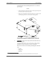
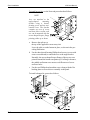
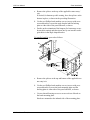
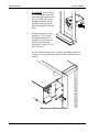
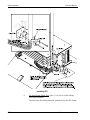
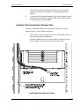
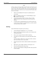
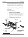
1
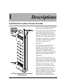
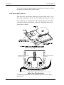
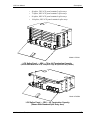
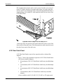
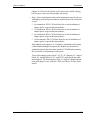
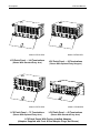
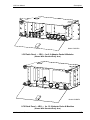
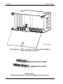
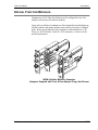
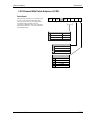
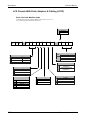
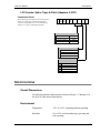
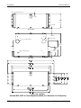
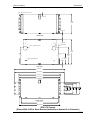
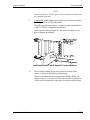
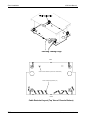
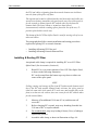
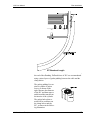
®
®
LCX FIBER PATCH/SPLICE PANEL
USER MANUAL
126254
Issue A Rev 0
LCX Fiber Patch/Splice Panel User Manual
Document Number 126254 Issue A Rev 0
Copyright© 2002, Telect, Inc., All Rights Reserved.
Telect® and Connecting the Future® are registered trademarks of Telect, Inc., 2111 N. Molter Rd., Liberty Lake,
Washington 99019
Technical Support:
By e-mail: [email protected]
By phone: 888-821-4856 or 509-921-6161
Note:
Telect assumes no liability from the application or use of these products. Neither does Telect convey any license under its patent rights nor the patent rights of others. This document and the products described herein are subject to
change without notice.
ii
Telect, Inc.
126254 A0
Contents
1 Descriptions
LCX Fiber Patch/Splice Panel Systems....................................... 1-1
Features .................................................................................. 1-2
Capacities/Capabilities/Suitability......................................... 1-2
Benefits .................................................................................. 1-2
LCX Fiber Panels......................................................................... 1-3
LCX Fiber Splice Panel ......................................................... 1-4
LCX Fiber Patch Panel .......................................................... 1-6
Special Function Modules ......................................................... 1-11
Model Number Configurators.................................................... 1-12
LCX Chassis Without Patch Adapters (LCXM).................. 1-12
LCX Chassis With Splice Trays (LCXS) ............................ 1-12
LCX Chassis With Patch Adapters (LCXP) ........................ 1-13
LCX Chassis With Patch Adapters & Cabling (LCXF) ...... 1-14
LCX Combo: Splice Trays & Patch Adapters (LCXC)....... 1-15
Specifications............................................................................. 1-15
Overall Dimensions ............................................................. 1-15
Environment......................................................................... 1-15
Certification ......................................................................... 1-16
2 Applications
Interconnecting IFC to Network Elements .................................. 2-1
Interconnecting Network Elements ............................................. 2-1
Cross-Connecting Network Elements.......................................... 2-2
Cross-Connecting Combinations ................................................. 2-3
Interconnecting & Cross-Connecting Along with Special Function
Modules ....................................................................................... 2-5
126254 A0
Telect, Inc.
iii
3 Panel Installation
Installation Considerations .......................................................... 3-1
Location & Space................................................................... 3-2
Tools & Equipment................................................................ 3-2
Inspection..................................................................................... 3-2
Installation Procedure .................................................................. 3-2
4 Fiber Installation
Splicing ........................................................................................ 4-1
Installing & Routing IFC Fiber.............................................. 4-2
Installing & Routing Network Element Fiber........................ 4-5
Splicing .................................................................................. 4-6
Patching ....................................................................................... 4-7
5 Service
Owner Maintenance ..................................................................... 5-1
Technical Support ........................................................................ 5-2
In-Warranty Service ..................................................................... 5-2
Out-Of-Warranty Service............................................................. 5-2
Repacking For Shipment ............................................................. 5-2
6 Accessories
iv
Telect, Inc.
126254 A0
1
Descriptions
LCX FIBER PATCH/SPLICE PANEL SYSTEMS
Telect’s LCX Patch/Splice Panel Systems
provide inter-connectivity and crossconnectivity of riser/plenum and network
element fiber cabling. Panels provide a
central location for patching, splicing,
testing, troubleshooting, monitoring, and
restoring service to fiber optic systems.
LCX panels fit standard 19-in. and 23-in.,
EIA/WECO and ETSI racks. 4RU and
5RU panels support up to 144
terminations.
LCX Patch Panels and Splice Panels
provide a total solution as well as
standalone splice and patch capabilities.
All Telect LCX panels are system
compatible with standard LGX® style
panels, thereby serving as replacements or
add-ons in system solutions of other
manufacture.
Telect offers LCX Panels uncabled, or
with convenient pre-cabled patch cabling
of any length. Patch adapter terminations
include ST, SC, FC, SC APC, & FC APC.
LCX Fiber Patch/Splice Panel System
(Total Solution)
126254 A0
Telect, Inc.
Uncabled LCX Patch Panels are also
available with or without fiber adapters;
Telect offers adapter packs with 6 or 12
adapters per pack for on-site configuration. Unadapterized 3RU & 4RU LCX
Patch Fiber Panels also accept standard
Wavelength Division Multiplexing
(WDM), splitter, and monitor modules.
1-1
Descriptions
LCX User Manual
Features
Telect manufactures LCX Patch Panels and Splice Panels to suit any
system architecture. Features include —
•
Designed for compliance (fiber bend radius control, flammability
safety, structural reliability). NEBS 3 and ETSI certificationl.
•
•
Zone 4 Seismic reliability.
Light weight.
•
Splice tray easily removed for rapid termination of cable.
•
No cassette required. Trays provide for easy and direct storage and
splicing.
•
Removable front and rear doors.
Capacities/Capabilities/Suitability
•
•
LCX panels are available for universal 19-in., 23-in., and ETSI racks.
48, 72, 96, or 144 terminations per panel (from 3RU to 5RU).
•
Standard-size 6 or 12 adapters per pack for on-site patch panel
adaptation of unadapterized panels.
ST, SC, FC, SC APC, FC APC single-mode and multimode adapters.
•
•
Standard-size Wavelength Division Multiplexing (WDM) and splitter
modules can be used along with adapter packs for added fexibility.
•
All LCX Patch/Splice panels are fully compatible with standard LGX®
style panels for IFC entrance, splicing, and network patching
architecture.
All LCX panels are compatible with Telect’s WaveTrax cable
management systems, as well as those of other manufacture.
Slip-on, split arcs standard for patch cord entrance; optional kits
available with hangers, hooks, and arcs to suit operating company
preferences.
Precabled Patch Panels — Any length of cable.
•
•
•
Benefits
Telect’s LCX Splice/Patch Panels are ideal for central office, head-end and
wiring centers. Benefits include —
•
•
•
1-2
Low cost — High Fiber Density — Versatility.
Easy Installation.
Simple, straight-forward cable management, access, circuit
identification and isolation.
Telect, Inc.
126254 A0
LCX User Manual
Descriptions
•
•
Easy access to riser/network/patch cord interconnections and crossconnections.
Compatibility.
LCX FIBER PANELS
Telect manufactures LCX Fiber Splice Panels and LCX Fiber Patch Panels
of various densities to suit company-wide fiber splice, patching, and
routing requirements.
All LCX Fiber Panels are metal chassis (3RU, 4RU, and 5RU) with
hinged/removable front and rear doors — shown in the following
illustration. All panels include cable entry from “outside the rack” near the
four corners of the panels. Knock-out holes at the top and bottom of the
panel allow for routing from splice panels to patch panels (and between
patch panels) vertically within the rack. Hole pattern and positions are
compatible with panels offered by other manufacturers, allowing
expansion and replacements of those systems using Telect’s low-cost LCX
panels.
LCX Fiber Panels (Common Physical Features)
Interconnection and cross-connection cabling from above or below enter at
the two front corners of each Telect LCX panel via radius control arcs,
hangers, or hooks. Eight split arcs are standard with each panel. These slip
over the edges of the chassis to protect cable entrance and control radius
bends within compliance requirements. Telect also offers three optional
126254 A0
Telect, Inc.
1-3
Descriptions
LCX User Manual
kits to satisfy cable management practices requiring arcs, hangers, or hooks
to separate and isolate groups of fiber cables.
LCX Fiber Splice Panel
Each splice tray, shown below, holds up to 24 splices along with 1½ m of
fiber cable storage below the tray for each subunit and interconnect cable.
Trays easily slip free of the panels to allow splicing. Storage spools and
splice holders are mounted directly on the tray, eliminating the need for
special splice cassettes.
Splice Tray (Right Corner View)
Stranded fiber from IFC is wound
around one of the spools...
Pigtail from NE is wound around
the other spool.*
From IFC
Tie-Down Locations for Cable Ties
To Network Elements
* Strands are always routed clockwise on the left spool and counter-clockwise on the right spool.
Splice Tray (Fiber Routing)
The following illustrations show termination capacities of LCX Fiber
Splice Panel:
1-4
Telect, Inc.
126254 A0
LCX User Manual
Descriptions
•
48-splice, 3RU LCX panel contains 2 splice trays
•
•
72-splice, 4RU LCX panel contains 3 splice trays
96-splice, 4RU LCX panel contains 4 splice trays
•
144-splice, 4RU LCX panel contains 6 splice trays
Model LCXS141
LCX Splice Panel — 4RU — 72 to 144 Termination Capacity
(Shown With Maximum of 6, 24-Splice Trays & Optional Entry Hooks)
Model LCXS481
LCX Splice Panel — 3RU — 48 Termination Capacity
(Shown With Standard Split Entry Arcs)
126254 A0
Telect, Inc.
1-5
Descriptions
LCX User Manual
IFC stranded cable from the splice vault is secured at either rear corner of
of the LCX Splice Panel by an optional cable clamp. (A single clamp fits
all sizes of IFC riser and plenum cable.) The following illustration shows a
clamp holding a 144-strand IFC cable installed at the left rear corner of an
LCX Splice Panel.
Optional Cable Clamp Fits All Sizes of IFC
Cable rings in the rear portion of the panel lead the IFC tubes to one of the
front corners of the splice trays. The interconnection cables enter the tray at
the other front corner of the splice tray.
LCX Fiber Patch Panel
LCX Fiber Patch Panels come in four capacities with or without fiber
adapters:
•
Page 1-7 shows four termination capacities of LCX Fiber Patch Panels
with factory-installed adapters.
◊
◊
◊
◊
48-termination, 3RU LCX Patch Panel with factory-installed adapters.
72-termination, 4RU LCX Patch Panel with factory-installed adapters.
96-termination, 4RU LCX Patch Panel with factory-installed adapters.
144-termination, 4RU LCX Patch Panel with factory-installed
adapters.
All are available with SC, SC/APC, FC, FC/APC, or ST single-mode
1-6
Telect, Inc.
126254 A0
LCX User Manual
Descriptions
adapters. LCX Fiber Patch Panels can be ordered pre-cabled with pigtails for quick setup, network patching, and startup.
•
Page 1-8 shows patch panels with similar termination capacities for use
with adapter packs and special-function modules that can be configured
on-site:
◊
◊
48-termination, 3RU LCX Patch Panel for on-site installation of
adapter packs or special-function modules.
72-termination, 4RU LCX Patch Panel for on-site installation of
adapter packs or special-function modules.
◊
96-termination, 4RU LCX Patch Panel for on-site installation of
adapter packs or special-function modules.
◊
144-termination, 5RU LCX Patch Panel for on-site installation of
adapter packs or special-function modules.
Each adapter pack contains 6 or 12 adapters, depending on the height
of the intended unadapterized panel; the adapters are mounted to a
standardized patch plate that snaps into the LCX bulkhead separating
the front and rear compartments of the panel.
Telect offers adapter packs with SC, ST, FC, SC (Duplex), FC Angled
Polish, SC Angled Polish, FC-SC, and ST-SC single-mode and multimode adapters. The illustrations on Page 1-9 show SC adapters mounted to patch plates for use with 3RU, 4RU, and 5RU LCX Fiber Patch
Panels.
126254 A0
Telect, Inc.
1-7
Descriptions
LCX User Manual
Model LCXP141SCU
LCX Patch Panel — 144 Terminations
(Shown With Standard Entry Arcs)
Model LCXP721SCU
Model LCXP961SCU
LCX Patch Panel — 96 Terminations
(Shown With Optional Entry Hangers)
Model LCXP482SCU
LCX Patch Panel — 72 Terminations
LCX Patch Panel — 48 Terminations
(Shown With Optional Entry Arcs)
(Shown With Standard Entry Arcs)
LCX Patch Panels With Factory-Installed Adapters
(Adapters Supplied with Front & Rear Adapter Plugs, Not Shown)
1-8
Telect, Inc.
126254 A0
LCX User Manual
Descriptions
Model LCMX3R2
LCX Patch Panel — 3RU — for 8, 6-Adapter Packs & Modules
(Shown With Standard Entry Arcs)
Model LCXM4R1
LCX Patch Panel — 4RU — for 12, 8-Adapter Packs & Modules
(Shown With Standard Entry Arcs)
126254 A0
Telect, Inc.
1-9
Descriptions
LCX User Manual
Model LCXM5R1
LCX Patch Panel — 5RU — for up to 12, 12-Adapter Packs & Modules
(Shown With Standard Entry Arcs)
Adapter Packs
(Adapters Supplied with Front & Rear Adapter Plugs, Not Shown)
1-10
Telect, Inc.
126254 A0
LCX User Manual
Descriptions
SPECIAL FUNCTION MODULES
Unadapterized LCX Fiber Patch Panels can be configured on-site with
adapter packs and special function modules.
Telect offers a full line of standard-size Wavelength Division Multiplexing
(WDM) modules and splitter modules that can be used in place of adapter
packs. Some special-function Telect modules are illustrated below. Call
Telect at 1-509-926-6000, 1-800-551-4567 (domestic), or telect.com for
detailed information.
WDM & Splitter Modules, Examples
(Adapters Supplied with Front & Rear Adapter Plugs, Not Shown)
126254 A0
Telect, Inc.
1-11
Descriptions
LCX User Manual
MODEL NUMBER CONFIGURATORS
LCX Chassis Without Patch Adapters (LCXM)
Modular Panel
The Modular panel is designed as a scalable
solution to support patch plates, couplers, splitters
or other Value Added Modules (VAMS).
L
52
70
90
C
X
-
M
Nominal Capacity
5.25” Chassis
3RU
7” Chassis
4 RU
9” Chassis
5RU
1
F
2
E
Mounting
19-Inch Standard
19-Inch Flush
23-Inch Standard
ETSI Flush
LCX Chassis With Splice Trays (LCXS)
L
C
X
-
S
Splice Panel
The splice panel is available in the listed densities. It is a
standard chassis with a drawer system integrated within.
Nominal Capacity
48 48 Terminations
5.25" (3RU)
72 72 Terminations
7" (4 RU)
96 96 Terminations
7" (4RU)
14 144 Terminations
7" (4RU)
1
F
2
E
1-12
Mounting
19-Inch Standard
19-Inch Flush
23-Inch Standard
ETSI Flush
Telect, Inc.
126254 A0
LCX User Manual
Descriptions
LCX Chassis With Patch Adapters (LCXP)
Patch Panel
The patch panel offers the users a termination point
for cross connect and interconnect applications.
Typically a jumper will be connected through the
front another jumper attached to the back.
Occasionally a Multifiber cable will be terminated
and attached at the factory. See below (Patch Panel
with Multifiber Cable)
L
C
X
-
P
Nominal Capacity
48 48 Terminations
5.25" (3RU)
72 72 Terminations
7" (4 RU)
96 96 Terminations
7" (4RU)
14 144 Terminations
7" (4RU)
Mounting
19-Inch Standard
19-Inch Flush
23-Inch Standard
ETSI Flush
1
F
2
E
S
N
F
D
T
126254 A0
Telect, Inc.
Adapter Type
Single Mode
SC/UPC
SC/APC
FC/UPC
FC/APC
ST/UPC
1-13
Descriptions
LCX User Manual
LCX Chassis With Patch Adapters & Cabling (LCXF)
Patch Panel with Multifiber Cable
A standard Patch panel may include a Multifiber cable in either a 48, 72, 96 or
two 72 cables terminated and attached at the factory.
CABLE LENGTH
M
METERS
F
FEET
L
C
X
-
F
-
Cable Length
XXX
005
020
100
Nominal Capacity
48 48 Terminations
5.25" (3RU)
72 72 Terminations
7" (4 RU)
96 96 Terminations
7" (4RU)
14 144 Terminations
7" (4RU)
T
Mounting
19-Inch Standard
19-Inch Flush
23-Inch Standard
ETSI Flush
1
F
2
E
S
N
F
D
T
1-14
Adapter Type
Single Mode
SC/UPC
SC/APC
FC/UPC
FC/APC
ST/UPC
G
Multifiber Cable Type
V
IFC Stranded Riser
W IFC Plenum Stranded
X
IFC Ribbon Riser
5 meter cable
20 meter cable
100 meter cable
Termination
High Speed Ultra Polish
™
(TeraBand )
Standard Ultra Polish
™
(GigaWave )
Multifiber Cable Exit Direction
A
Up Right
B
Up Left
C
Down Right
D
Down Left
Telect, Inc.
126254 A0
LCX User Manual
Descriptions
LCX Combo: Splice Trays & Patch Adapters (LCXC)
Combination Panel
The combination panel integrates both a patch and splice
chassis into a single unit (2 chassis bolted together).
Customers will purchase this for an on-frame splicing
solution, or in a space-constrained environment.
L C X - C
Nominal Capacity
48 48 Terminations
5.25" (3RU)
72 72 Terminations
7" (4 RU)
96 96 Terminations
7" (4RU)
14 144 Terminations
7" (4RU)
Mounting
19-Inch Standard
19-Inch Flush
23-Inch Standard
ETSI Flush
1
F
2
E
S
N
F
D
T
Adapter Type
Single Mode
SC/UPC
SC/APC
FC/UPC
FC/APC
ST/UPC
SPECIFICATIONS
Overall Dimensions
Overall SAE and metric dimensions are shown on Pages 1-17 through 1-19
for all LCX Fiber Splice/Patch Panels.
Environment
126254 A0
Temperature:
-55ºC to +85ºC, operating and non-operating
Humidity:
0% to 95% and noncondensing, operating and
non-operating
Telect, Inc.
1-15
Descriptions
LCX User Manual
Certification
UL 60950
CE EN 60950
Bellcore GR-63-CORE
Bellcore GR-1089-CORE
ETSI EN 300 019-2-(1,2,3)
1-16
Telect, Inc.
126254 A0
LCX User Manual
Descriptions
Note: Dimensions are in mm (in.).
132.00
(5.20)
2.22 (0.09)
REAR VIEW
7.10 (0.28)
25.25 (0.99)
44.4 (1.75) Dia. Knockout
273
(10.75)
187.25
(7.37)
6.5 (.26) Dia. Bolt Hole
114.62
7.10 (4.51)
(0.28)
TOP VIEW
3RU LCX Chassis
(Shown With 19/23-in. Rack Bracket Installed for a Nominal 5-in. Extension)
126254 A0
Telect, Inc.
1-17
Descriptions
LCX User Manual
Note: Dimensions are in mm (in.).
1.6 (0.06)
173.75
(6.84)
2.22 (0.09)
REAR VIEW
7.10 (0.28)
25.25 (0.99)
44.4 (1.75) Dia. Knockout
273
(10.75)
187.25
(7.37)
6.5 (.26) Dia. Bolt Hole
114.62
7.10 (4.51)
(0.28)
TOP VIEW
4RU LCX Chassis
(Shown With 19/23-in. Rack Bracket Installed for a Nominal 5-in. Extension)
1-18
Telect, Inc.
126254 A0
LCX User Manual
Descriptions
Note: Dimensions are in mm (in.).
2.85 (0.11)
216.98
(8.54)
2.24 (0.09)
REAR VIEW
7.10 (0.28)
25.25 (0.99)
44.4 (1.75) Dia. Knockout
273
(10.75)
187.25
(7.37)
6.5 (.26) Dia. Bolt Hole
114.62
7.10 (4.51)
(0.28)
TOP VIEW
584.2 (23)
566.73 (22.3)
482.6 (19)
465.13 (18.3)
FRONT VIEW
432.5 (17.03)
468.05 (18.43)
5RU LCX Chassis
(Shown With 19/23-in. Rack Bracket Installed for a Nominal 5-in. Extension)
126254 A0
Telect, Inc.
1-19
Descriptions
1-20
LCX User Manual
Telect, Inc.
126254 A0
2
Applications
This section covers fundamental cross-connection and interconnection
techniques using Telect’s LCX Fiber Panels.
NOTE
Stranded or ribbon fiber should always enter or leave LCX panels in tieddown tubes, sheathed cable, or flex tubing.
INTERCONNECTING IFC TO NETWORK ELEMENTS
The illustration that follows shows a simple interconnection scheme
wherein OSP is spliced at a vault to IFC plenum or riser cable which, in
turn, is spliced at an LCX Fiber Splice Panel to the network elements.
Splice Vault
LCX Fiber Splice Panel
Subunit Tube
OSP
IFC
900µm
Sheathed
Cable
2 - 3 mm
To Network Elements
Interconnecting/Splicing Facility Cable to Network Elements
INTERCONNECTING NETWORK ELEMENTS
In the following illustration, fiber from one set of network elements is interconnected to a second set.
126254 A0
Telect, Inc.
2-1
Applications
LCX User Manual
LCX Fiber Patch Panel
To/From NE1s
Use rings to help guide
and organize strands,
ribbon, tubing, and
cable into smooth, neat
groups.
Cables and tubes must be secured to tie
downs using supplied or other restraint
on entering and leaving panel
2 mm, 3 mm , or
Multifiber Sheathed
Cable
Tie Down for Restraint
Velco-Style Retrains
are Supplied
From/To NE2s
Interconnecting Network Elements
CROSS-CONNECTING NETWORK ELEMENTS
In a variation of “Interconnecting Network Elements” NE1s and NE2s are
connected to the rear of two LCX Fiber Patch Panels with the fronts reserved for patch cords to cross-connect the two.
The following illustration shows a stylized version of this application.
NE1 Pigtails
Network
Element 1
NE2 Pigtails
I
O
Rear
Front
Front
Rear
Patch Cords
LCX Fiber Patch Panel
Cross-Connecting Network Elements
2-2
Telect, Inc.
126254 A0
LCX User Manual
Applications
CROSS-CONNECTING COMBINATIONS
LCX Fiber Splice and Patch Panels can be used in combination to crossconnect IFC to network elements.
The following illustration shows a 48-fiber LCX Combination Panel (a 48fiber LCX Splice Panel bolted to a 48-fiber LCX Patch Panel). After the incoming IFC is spliced, the fiber strands are passed through the 1½ in. (38.1
mm) diameter hole in the top of the splice shelf to the patch shelf. Notice
that plastic grommets (supplied) are used to protect an unsheathed fiber
strand passing through holes to an upper panel.
NOTE
If you create your own combination LCX Splice and Patch Panel onsite, remember to remove knockout plugs at the top and bottom of LCX panels before installing panels in racks. (Knockouts can be removed and plastic
grommets can be installed after panels are racked, but it’s easier before
panels are racked.) Avoid removing the knockouts on the top of the top
most and bottom of the bottom most LCX panels. The knockout plugs provide fire abatement.
126254 A0
Telect, Inc.
2-3
Applications
LCX User Manual
To NEs
48-Fiber IFC
Sheathed Cable
or Patch Cords
Use flex tubing or other
sheathing wherever possible
to protect unsheathed fiber
strands and ribbon.
Plastic grommets (4)
are installed between
combo panels at the
factory
Subunit
Dimples with bolt holes
Holes allow panels to be
bolted together and handled
as a unit.*
Tie Downs. Use Velcro-style strips,
Leave fire-abatement knockouts in
(supplied) or other restraint
place at the top of the topmost
whereever cable or tubing
LCX panel and at the bottom of
enters or exits panels or trays.
the lowermost panel.
Never retrain unprotected fiber
(individual strands or ribbon); always place strands
or ribbon in protective tubing before restraining.
* Combination LCX panels (patch panel on top; splice panel on bottom) are bolted together at the factory.
Cross-Connecting IFC to Network Elements
2-4
Telect, Inc.
126254 A0
LCX User Manual
Applications
INTERCONNECTING & CROSS-CONNECTING ALONG WITH SPECIAL FUNCTION MODULES
Wavelength Division Multiplexing (WDM) and splitter modules can be
used in LCX panels.
The illustration that follows show one way a 48-fiber IFC is spliced and
then interconnected via splitters/WDMs to network elements.
Notice that three, 3RU LCX Configurable Panels with dual, 1-to-3 splitters
(or dual WDMs) are required for splitting/demultiplexing the 48 incoming
fiber signals.
Dedicated LCX Patch Panels can be used to interconnect/cross-connect the
split/demultiplexed signals with the network elements. In such case,
•
•
126254 A0
Telect, Inc.
splitting 48 signals three ways requires a 4RU LCX Patch Panel with
144 adapters (or a 5RU LCX Configurable Patch Panel with the same
number of adapters)
demultiplexing 48 signals into two wavelengths requires a 4RU LCX
Patch Panel with 96 adapters (or a 5RU LCX Configurable Patch Panel).
2-5
Applications
LCX User Manual
A single, factory-configured 4RU Fiber
Patch Panel (or a 5RU configurable panel)
can be used for centralized patching of
outputs from the splitters.
144-Fiber, 4RU LCX Patch Panel
To 144 NEs
Three, 3RU LCX Configurable Patch Panels
with eight, 1-to-3 dual splitters can be used
to terminate spliced strands from a
single 48-fiber LCX Fiber Splice Panel.
48-Fiber IFC
One of Three, 3RU LCX Configurable Patch Panels
48-Fiber, 3RU LCX Fiber Splice Panel
Interconnecting/Cross-Connecting Along with WDM/Splitter Modules
2-6
Telect, Inc.
126254 A0
3
Panel Installation
INSTALLATION CONSIDERATIONS
!
WARNING
WARNING! Fiber cables transmit invisible infrared light. To
avoid eye damage or blindness, never look directly into fibers
or connectors.
WARNUNG! Faserkabel übertragen unsichtbares Infrarotlicht.
Um eine Schädigung der Augen oder
Blindheit zu vermeiden, schauen Sie nicht direkt in die Fasern
oder Stecker.
ADVERTENCIA ! Los cables de fibra transmiten luz láser o
infrarroja invisible. Para evitar lesiones
oculares o ceguera, nunca mire directamente a las fibras o
conectores.
ADVERTISSMENT ! Les câbles à fibres transmettent un rayon
laser ou une lumière infrarouge invisible. Pour éviter toute
lésion occulaire ou cécité, ne regardez jamais directement
dans les fibres ou dans les connecteurs.
!
ALERT
ALERT! This product must be installed and maintained only by
qualified technicians.
!
ALERT
ALERT! These instructions presume you have verified that the
Telect equipment being installed is compatible with the rest of
the system, including power, ground, circuit protection, signal
characteristics, equipment from other vendors, and local codes
or ordinances.
126254 A0
Telect, Inc.
3-1
Panel Installation
LCX User Manual
Location & Space
LCX Fiber Panels are configured at the factory for either —
•
standard 19 in., 23 in., or ETSI racks;
•
WECO and EIA spacing on 19 in. and 23 in. brackets;
•
face flush with front rack flange or nominal 5 in. extension beyond
front rack flange.
Plan the input/output, upward/downward (cable feed) layout of each panel
and its position in the rack before beginning LCX panel installation. If you
plan to pass fiber strands, cable, and/or tubing through the knocked-out
holes in the tops and bottoms of the panels, the panels should be mounted
in contiguous vertical rack spaces.
Tools & Equipment
No special tools required.
INSPECTION
Telect is not liable for shipping damage.
Keep the container until you have checked equipment operation. If you
experience any kind of problem, call Telect’s Customer Service
Department. Use the original, undamaged container if you are instructed to
return a panel to Telect.
If a shipping container is damaged, keep it for the carrier’s inspection.
Notify the carrier and call Telect’s Customer Service Department at
1-800-551-4567 or 1-509-926-6000
INSTALLATION PROCEDURE
Prepare, mount, and insert modules and cable management rings in all
panels in a rack before cabling any panels in the rack.
1.
3-2
If applicable, if you plan to pass fiber strands, cables, and/or tubing
through the 1½ in. (38.1 mm) diameter holes in the tops and bottoms of panels, see the Notes below and then knock out the applicable fire-abatement plugs covering these holes, as shown in the fol-
Telect, Inc.
126254 A0
LCX User Manual
Panel Installation
lowing illustration. Insert standard grommets for 1½ in. holes in
place of plugs.1
NOTES
•
Avoid removing fire-abatement plugs on the top of the top most
and bottom of the bottom most panel.
•
Plugs can be knocked out when the panels are in place on the
rack. But plug removal is easiest before racking panels.
Removing Knockouts & Installing Plastic Grommets
2.
If applicable, install optional entry/exit kit at the front and/or rear
corners of the panel.
An optional entry/exit kit can be used in place or along with the
eight split arcs at the front and rear corners of the panel.
Three kits are offered, each containing mounting plates and hardware:
•
•
•
1.
Arc Kit
Hanger Kit
Hook Kit
LCXC Fiber Splice and Patch Panels have plastic grommets already installed between the combination panels.
126254 A0
Telect, Inc.
3-3
Panel Installation
LCX User Manual
To install an arc kit, see the Note and procedure that follows:
NOTE
Arcs are attached to the
angle-shaped
mounting
bracket using a threadforming screw and an antirotation boss. The bracket
contains two sets of screw
and boss holes so that each
arc can be mounted with the
arrow-shaped keeper flange
pointing either up or down.
a. Remove the split arc at
the top of the applicable corner entry/exit.
Leave the split arc at the bottom in place, as shown in the preceding illustration.
b. Use the three thread-forming Phillips head screws (screws with
cross-recessed heads) to attach the arcs to the angle bracket.
Normally, the arrow-shaped keeper flange of the top two arcs
point down and the bottom one points up. For flange clearance,
the middle and bottom arcs must use a different set of screw
and boss holes.
c. Use the two Phillips head machine screws along with the flat
backing plate to secure this arc assembly to the panel.
To install a hanger kit, proceed as follows:
3-4
Telect, Inc.
126254 A0
LCX User Manual
Panel Installation
a. Remove the split arc at the top of the applicable corner entry/
exit.
If desired, for bottom-up cable routing, leave the split arc at the
bottom in place, as shown in the preceding illustration.
b. Use the two Phillips head machine screws (screws with crossrecessed heads) to secure the angle bracket and flat backing
plate to either side of the panel sidewall, as shown.
c. Decide on the orientation of the hangers (for bottom-up or topdown cable routing) and then insert one by one into the rectangular holes in the angle-shaped bracket.
To install a hook kit, proceed as follows:
a. Remove the split arc at the top and bottom of the applicable corner entry/exit.
b. Use the two Phillips head machine screws (screws with cross
recessed heads) to secure the hook mounting plate and flat
backing plate to either side of the panel sidewall, as shown.
c. Use two thread-forming screws to secure each set of hooks to
the hook mounting plate.
Hooks are mounted to the inboard side of the mounting plate.
126254 A0
Telect, Inc.
3-5
Panel Installation
LCX User Manual
3.
If applicable, for pre-cabled
LCX patch panels, place the
panel and pigtail spool/coil at
the rear of the rack, remove
shipping restraints, uncoil
pigtails, and then pass the
panel through the rack to the
front.
4.
Mount each panel to rack
using four, 12-24, threadforming mounting screws
(supplied, two per side), as
shown in the following
illustration. Torque to 35 in.lbs (4.29 N•m.).
For one of the mounting screws, include a ground lug and star
washer. (Use one ground lug with #14 AWG stranded wire per
chassis.)
Mounting LCX Panel to Rack
3-6
Telect, Inc.
126254 A0
LCX User Manual
Panel Installation
NOTE
Each shelf of an LCX Fiber Splice/Patch Combination Panel must
be grounded separately.
5.
If applicable, install adapter packs and/or special function modules
in configurable LCX Fiber Patch Panel.
The following illustration shows a 6-adapter pack being installed in
a 4RU LCX Fiber Configurable Patch Panel.
Push in quick-connect plungers at either end of faceplate to lock
pack or module in bulkhead.
Installing Adapter Pack & Special Function Modules
6.
Place a plastic cabling ring at each of the four corners of the
chassis, as shown in the following illustrations.
Rings can be added and moved around later during cabling. The
rings not only serve as corrals for fiber cable but also as guideposts.
Cables can be inserted in the split rings or routed around the rings.
126254 A0
Telect, Inc.
3-7
Panel Installation
LCX User Manual
Inserting Cabling Rings
REAR
Cable Tie-Down Positions (one at each entrance/exit)
Plastic Cabling Ring Positions (14)
FRONT
Cable Restraint Layout (Top View of Chassis Bottom)
3-8
Telect, Inc.
126254 A0
LCX User Manual
126254 A0
Telect, Inc.
Panel Installation
3-9
Panel Installation
3-10
LCX User Manual
Telect, Inc.
126254 A0
4
Fiber Installation
!
WARNING
WARNING! Fiber cables transmit invisible infrared light. To
avoid eye damage or blindness, never look directly into fibers
or connectors.
WARNUNG! Faserkabel übertragen unsichtbares Infrarotlicht.
Um eine Schädigung der Augen oder Blindheit zu vermeiden,
schauen Sie nicht direkt in die Fasern oder Stecker.
ADVERTENCIA ! Los cables de fibra transmiten luz láser o
infrarroja invisible. Para evitar lesiones oculares o ceguera,
nunca mire directamente a las fibras o conectores.
ADVERTISSMENT ! Les câbles à fibres transmettent un rayon
laser ou une lumière infrarouge invisible. Pour éviter toute
lésion occulaire ou cécité, ne regardez jamais directement
dbase of the Main or InterBay Storage Panels.
SPLICING
Splicing begins with installation of the IFC at the rear of the LCX Fiber
Splice Panel.
Each stranded or ribbon IFC subunit contains up to 12 fibers and each
LCX splice tray handles up to 24 splices — two subunits of fiber.
Pairs or groups of tubes containing stranded or ribbon fiber enter the
designated tray at one of the front corners (with the other corner reserved
for corresponding fibers originating from network elements). Tubes from
126254 A0
Telect, Inc.
4-1
Fiber Installation
LCX User Manual
the IFC and cables originating from the network elements are tied down
near the front of the splice tray floor.
The unprotected strands or ribbon from the tied-down tubes and cables are
wound several times around the two spools on the tray. One of the spools is
for the strands or ribbon from the IFC and the other for the network
element leads. The loose ribbon or strands are then spliced
(interconnected) with the resulting splices placed in one of the two, 12position splice holders on the tray.
The bottom of the LCX Fiber Splice Panel is used for storing coils of excess
tubes and cables.
The paragraphs that follow contain installation and routing procedures
required for splicing IFC to network elements:
•
Installing & Routing IFC Fiber and
•
Installing & Routing Network Element Fiber
Installing & Routing IFC Fiber
An optional cable clamp is required for installing IFC to an LCX Fiber
Splice Panel. (See Accessories, Section 6.)
1.
Route IFC to a rear corner entrance of the LCX Fiber Splice Panel,
as shown in the following illustration.
IFC can be routed from the bottom up or top down at either rear
corner of the splice panel.
NOTE
Coiling, routing, and storage of fiber from IFC and network elements work
best if the IFC and network element leads exit/enter the splice panel at
either the same side of the panel (IFC at the rear and network fiber at the
front) or at the two rear corners (one rear corner for the IFC and the other
for the network fiber).
4-2
2.
Measure off an additional 2110 mm (83 in.) and then trim off
excess IFC.
3.
Before clamping IFC to panel, strip away sheathing from this last
2110 mm of IFC to expose subunits.
4.
For stranded cable, strip away leading 610 mm (24 in.) of tubing to
expose 900 µm fiber.
5.
Assemble cable clamp, as shown in illustration on Page 4-4.
Telect, Inc.
126254 A0
LCX User Manual
Fiber Installation
IFC Breakout Length
Each IFC clamp consists of clamp halves that fit around the IFC at
the end of the sheathing. Different sizes of IFC are accommodated
using various layers of gasket padding between the cable and the
clamp halves.
The gasket padding kit contains a cylinder of gasket
leaves, as shown on the
right. Measure the diameter
of the IFC and then remove
and discard that much from
the interior of the cylinder.
The gasket halves that remain will be used between
the clamp halves and the
IFC, as shown in the following illustration.
126254 A0
Telect, Inc.
4-3
Fiber Installation
LCX User Manual
Installing IFC
6.
For unprotected ribbon fiber, place 1½ m (59 in.) of flex tubing
over exposed ribbon.
The end of the flex tubing should be pushed back to the IFC clamp.
4-4
Telect, Inc.
126254 A0
LCX User Manual
Fiber Installation
7.
Select pairs or groups of tubing for each tray. Tape or tie these
together and allow tubes to hang out the front of the panel for
splicing.
8.
As shown in the preceding illustration, place tubes in plastic ring at
panel entrance and then use supplied cable ties (or other restraint)
to tie down tubes to floor of panel.
Installing & Routing Network Element Fiber
Network element fiber cable enters the panel at either the rear corner
opposite the IFC or one of the front corners.
1.
Route cable to a corner entrance of the LCX Fiber Splice Panel, as
shown in the following illustration.
Network element leads can be routed from the bottom up or top
down at either a rear or front corner of the splice panel.
Installing Network Element Cables
126254 A0
Telect, Inc.
4-5
Fiber Installation
LCX User Manual
NOTE
Coiling, routing, and storage of fiber from IFC and network elements work
best if the IFC and network element leads exit/enter the splice panel at
either the same side of the panel (IFC at the rear and network fiber at the
front) or at the two rear corners (one rear corner for the IFC and the other
for the network fiber).
2.
Measure off an additional 2110 mm (83 in.) and then trim off
excess cable.
3.
Strip away leading 610 mm (24 in.) of cable sheathing to expose
either stranded or ribbon fiber.
4.
Select pairs or groups of cable for each tray. Tape or tie these
together and allow cables to hang out the front of the panel for
splicing.
5.
As shown in the preceding illustration, place cables in plastic ring
at panel entrance and then use supplied cable ties (or other restraint)
to tie down cables to floor of panel.
Splicing
Start with the bottom most splice tray and work up.
1.
Locate splicing unit within about 1½ m (~5 ft) of panel.
2.
Remove tray from panel and remove splice cover, as shown in the
following illustrations.
3.
Select a pair or group of tubes and cables for splicing.
4.
Use cable ties or other restraint to secure tubes and cables to floor
of tray.
Note that strands or ribbon always emerge from cables or tubes at
the tie down furthest from its tray entrance.
4-6
5.
Wrap the unprotected strands or ribbon around the nearby adjacent
spool.
6.
Make splices, place in holder, and then re-attach splice cover.
7.
Fill out tray label and affix to front of tray.
8.
Place tray in panel and then coil tubing and cables, and lay them flat
on floor of panel.
Telect, Inc.
126254 A0
LCX User Manual
Fiber Installation
Splice Tray (Right Corner View)
Stranded fiber from IFC is wound
around one of the spools...
Pigtail from NE is wound around
the other spool.*
From IFC
Tie-Down Locations for Cable Ties
To Network Elements
* Strands are always routed clockwise on the left spool and counter-clockwise on the right spool.
Splice Tray (Fiber Routing)
PATCHING
LCX Fiber Patch Panels can be used to either interconnect or crossconnect network elements: normally,
•
•
•
126254 A0
Telect, Inc.
To interconnect IFC splices from the LCX Fiber Splice Panel to network elements; or
To interconnect one system of network elements to another, as in a demarcation; or
To cross-connect network elements within the same system.
4-7
Fiber Installation
LCX User Manual
In all cases, pigtails (connectorized leads) from the splice panel or network
elements are connected to adapters on one side of the patch panel’s
bulkhead. Corresponding adapters on the other side of the bulkhead are
used for interconnecting or cross-connecting complementary network
element pigtails or patch cords.
Pigtails and patch cords1 can enter the LCX Fiber Patch Panel at any of
the four corners and are confined by a plastic ring and tie-down.
Additional plastic rings assist in routing the pigtails and patch cords to the
designated adapter.
To install pigtails or patch cords,
1.
Refer to the following illustration and route pigtails or patch cords
through a plastic ring located at the panel entrance.
2.
In the panel’s front compartment, use additional plastic rings to sort
and route pigtails or cords from the tie-down to the adapter.
3.
Pull out or unscrew the adapter plug and insert the pigtail or patch
cord connector.
4.
After installing pigtails/patch cords use cable ties or other restraints
to tie down the pigtails/cords to the floor of the panel.
Installing Interconnects or Cross-Connects in an LCX Fiber Patch Panel
1.
4-8
Normally, the patch cords enter at a front corner and connect to adapters on the front of the bulkhead.
Telect, Inc.
126254 A0
5
Service
!
WARNING
WARNING! Fiber cables transmit laser or invisible infrared
light. To avoid eye damage or blindness, never look directly
into fibers or connections.
WARNUNG! Faserkabel übertragen unsichtbares Infrarotlicht.
Um eine Schädigung der Augen oder Blindheit zu vermeiden,
schauen Sie nicht direkt in die Fasern oder Stecker.
ADVERTENCIA ! Los cables de fibra transmiten luz láser o
infrarroja invisible. Para evitar lesiones oculares o ceguera,
nunca mire directamente a las fibras o conectores.
ADVERTISSMENT ! Les câbles à fibres transmettent un rayon
laser ou une lumière infrarouge invisible. Pour éviter toute
lésion occulaire ou cécité, ne regardez jamais directement
dbase of the Main or InterBay Storage Panels.
!
ALERT
ALERT! This product must be installed and maintained by
qualified technicians.
OWNER MAINTENANCE
Telect’s LCX Fiber Panels need no preventive maintenance.
126254 A0
Telect, Inc.
5-1
Service
LCX User Manual
TECHNICAL SUPPORT
By e-mail: [email protected]
By phone: 888-821-4856 or 509-921-6161
IN-WARRANTY SERVICE
Contact your Telect equipment distributor, or call a Telect Customer
Service Representative:
1-800-551-4567
1-509-926-6000
Telect will repair or replace defective products within the limits of the
warranty. See “Repacking for Shipment” in this section.
NOTE
Call a Customer Service Representative for a Return Material
Authorization (RMA) before returning any equipment.
OUT-OF-WARRANTY SERVICE
The procedure for out-of-warranty service is the same as for in-warranty
service, except that Telect charges a processing fee, and you must submit a
Purchase Order along with a Return Material Authorization (RMA) before
returning equipment. Call a Customer Service Representative for help
getting these forms.
The processing fee guarantees a repair estimate and is credited against
actual material and labor costs.
REPACKING FOR SHIPMENT
5-2
1.
Tag the equipment showing owner’s name, address, and telephone
number, together with a detailed description of the problem.
2.
Use the original shipping container if possible. If you do not have
it, package the equipment in a way to prevent shipping damage.
Telect, Inc.
126254 A0
LCX User Manual
Service
Include the RMA inside the container and legibly print the RMA
number on the outside of the package, near the shipping address.
3.
Insure the package.
NOTE
Telect is not liable for shipping damage.
126254 A0
Telect, Inc.
5-3
Service
5-4
LCX User Manual
Telect, Inc.
126254 A0
6
Accessories
LCX Accessories and replacement items are listed in the following table.
Contact Telect for price and availability.
Item
6-Adapter Packs1
Description
SC (Duplex), Multimode
LP-6MMSCD
SC (Zirconia), Multimode
LP-6MMS
SC (with 8° Polish), Single Mode
LP-6SMN
SC (Duplex), Single Mode
LP-6SMSCD
SC (Zirconia), Single Mode
LP-6SMS
FC (Zirconia), Multimode
LP-6MMF
FC (with 8° Polish), Single Mode
LP-6SMD
FC (Zirconia), Single Mode
LP-6SMF
FC-SC, Single Mode
ST (Zirconia), Multimode
12-Adapter Packs2
126254 A0
Telect, Inc.
Part Number
LP-6SMF-S
LP-6MMT
ST (Zirconia), Single Mode
LP-6SMT-P
ST-SC, Single Mode
LP-6SMT-S
Blank (without adapters)
LP-6BLNK
SC (with 8° Polish), Single Mode
LP-12SMN
SC (Duplex), Single Mode
LP-12SMSCD
SC (Zirconia), Single Mode
LP-12SMS
FC (with 8° Polish), Single Mode
LP-12SMD
6-1
Accessories
L:CX User Manual
Item
12 Pack (Cont)
Description
Part Number
FC (Zirconia), Single Mode
LP-12SMF
FC-SC, Single Mode
LP-12SMF-S
ST (Zirconia), Single Mode
LP-12SMT
ST-SC Single Mode
IFC Clamp Kit
LP-12SMT-S
Clamp, mtg plate, gasket, & hardware
KIT-CLMP
Radius Cable Management Arc Kit3
KIT-CMGMT1
Isolation Hook Kit4
KIT-CMGMT2
Cable Management Hanger Kit5
KIT-CMGMT3
48-Port Designation Card
KIT-LABEL48
72-Port Designation Card
KIT-LABEL72
96-Port Designation Card
KIT-LABEL96
144-Port Designation Card
KIT-LABEL14
Smoked Plastic Door (5.25"H) for 3RU
KIT-LDOOR5
Smoked Plastic Door (7"H) for 4RU
KIT-LDOOR7
Smoked Plastic Door (9"H) for 5RU
KIT-LDOOR9
19" Std (22"W x 12"D x 7’H), WHT
071-6000-0001
23” Std (26"W x 12"D x 7’H), WHT
071-6000-0007
Relay Rack End Panel
12"D x 7’H (either side of rack), WHT
071-6000-0020
InterBay Management Panel
5"W x 7’H (either side of rack), WHT
071-6000-0023
Entry/Exit Cable Management
Designation Cards6
Transparent Front Doors
Network Relay Rack
1.
2.
3.
4.
5.
6.
6-2
Fits 3RU and 4RU LCXM chassis.
Fits 5RU LCXM chassis.
Kit contains three arcs, mounting plates, and hardware for each of two panel entries/exits. (Fits front or rear corners of
3, 4, and 5RU LCX panels.)
Kit contains two sets of plastic hooks, mounting plates, and hardware for each of two panel entries/exits. (Fits front or
rear corners of 3, 4, and 5RU LCX panels. 3RU LCX panels can accommodate only one set of plastic hooks.)
Kit contains three hangers, mounting plates, and hardware for each of two panel entries/exits. (Fits front or rear corners
of 3, 4, and 5RU LCX panels.)
Attaches to hangers located on inside face of LCX Fiber Patch Panel front door.
Telect, Inc.
126254 A0
Telect, Inc.
2111 N. Molter Rd.
P.O. Box 665, Liberty Lake, WA 99019
509-926-6000, 800-551-4567, Fax 509-926-8915
E-mail: [email protected] Internet: http://www.telect.com