1
Keysight 53210A
350 MHz RF Counter
User’s Guide
Notices
© Keysight Technologies 2011, 2014
Technology Licenses
No part of this manual may be reproduced in
any form or by any means (including electronic
storage and retrieval or translation into a foreign language) without prior agreement and
written consent from Keysight Technologies as
governed by United States and international
copyright laws.
The hardware and/or software described in this
document are furnished under a license and
may be used or copied only in accordance with
the terms of such license.
Manual Part Number
53210-90001
Edition
Edition 3, August 2014
Printed in Malaysia
Keysight Technologies
1400 Fountaingrove Parkway
Santa Rosa, CA 95403 USA
Product manuals are provided with your instrument on CD-ROM and/or in printed form.
Printed manuals are an option. Manuals are
also available on the web on the instrument’s
product page.
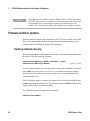
Software Updates / Licenses
Periodically, Keysight releases software
updates to fix known defects and incorporate
product enhancements. To search for software
updates and the latest documentation for your
product, go to the product page at:
www.keysight.com/find/53210A
A portion of the software in this product is
licensed under terms of the General Public
License Version 2 (“GPLv2”). The text of the
license and source code can be found at:
www.keysight.com/find/GPLV2
This product utilizes Microsoft Windows CE.
Keysight highly recommends that all Windows-based computers connected to
Windows CE instruments utilize current antivirus soft-ware. For more information, go to
the product page at:
www.keysight.com/find/53210A
2
Declaration of Conformity
Declarations of Conformity for this product and
for other Keysight products may be downloaded
from the Web. Go to http://www.keysight.com/
go/conformity and click on “Declarations of
Conformity.” You can then search by product
number to find the latest version.
Warranty
available. Contact your nearest Keysight
Sales and Service office for further
information on Keysight Technologies' full line
of Support Programs.
Certification
Keysight Technologies certifies that this
product met its published specifications at
time of shipment from the factory. Keysight
Technologies further certifies that its
calibration measurements are traceable to the
United States National Institute of Standards
and Technology, to the extent allowed by the
Institute's calibration facility, and to the
calibration facilities of other International
Standards Organization members.
The material contained in this document is provided “as is,” and is
subject to being changed, without
notice, in future editions. Further,
to the maximum extent permitted
by applicable law, Keysight
disclaims all warranties, either
express or implied, with regard to
this manual and any information
contained herein, including but not
limited to the implied warranties of
merchantability and fitness for a
particular purpose. Keysight shall
not be liable for errors or for
incidental or consequential damages
in connection with the furnishing,
use, or performance of this
document or of any information
contained herein. Should Keysight
and the user have a separate written
agreement with warranty terms
covering the material in this
document that conflict with these
terms, the warranty terms in the
separate agreement shall control.
Exclusive Remedies
Assistance
Microsoft and Windows are U.S. registered
trademarks of Microsoft Corporation.
This product comes with the standard product
warranty. Warranty options, extended support
contacts, product maintenance agreements
and customer assistance agreements are also
THE REMEDIES PROVIDED HEREIN ARE
THE CUSTOMER'S SOLE AND EXCLUSIVE
REMEDIES. KEYSIGHT TECHNOLOGIES
SHALL NOT BE LIABLE FOR ANY DIRECT,
INDIRECT, SPECIAL, INCIDENTAL, OR
CONSEQUENTIAL DAMAGES, WHETHER
BASED ON CONTRACT, TORT, OR ANY
OTHER LEGAL THEORY.
Restricted Rights Legend
U.S. Government Restricted Rights. Software
and technical data rights granted to the federal
government include only those rights customarily provided to end user customers. Keysight
provides this customary commercial license in
Software and technical data pursuant to FAR
12.211 (Technical Data) and 12.212 (Computer
Software) and, for the Department of Defense,
DFARS 252.227-7015 (Technical Data - Commercial Items) and DFARS 227.7202-3 (Rights
in Commercial Computer Software or Computer Software Documentation).
Trademarks
53210A User’s Guide
Waste Electrical and Electronic
Equipment (WEEE) Directive
2002/96/EC
This product complies with the WEEE Directive
(2002/96/EC) marking requirement. The affixed
product label (see below) indicates that you
must not discard this electrical/electronic product in domestic household waste.
Product Category: With reference to the
equipment types in the WEEE directive Annex
1, this product is classified as a "Monitoring
and Control instrumentation" product.
Do not dispose in domestic household waste.
To return unwanted products, contact your
local Keysight office, or see
www.keysight.com/environment/product
for more information.
Safety Information
The following general safety precautions must
be observed during all phases of operation of
this instrument. Failure to comply with these
precautions or with specific warnings or operating instructions in the product manuals violates
safety standards of design, manufacture, and
intended use of the instrument. Keysight Technologies assumes no liability for the customer's
failure to comply with these requirements.
General
Do not use this product in any manner not
specified by the manufacturer. The protective
features of this product may be impaired if it is
used in a manner not specified in the operation
instructions.
Before Applying Power
Verify that all safety precautions are taken.
Note the instrument's external markings
described under "Safety Symbols".
Lithium Battery Recycling
The 53210A counter contains a 3V “coin cell”
lithium battery. Keysight recommends that this
battery be replaced every year at the instrument’s 1-year calibration interval.
Replacement procedures are provided in the
53210A/53220A/53230A Service Guide.
Option 300 provides battery operation of the
53210A using a 12 lithium battery. Performance of this battery will degrade over time as
a function of the number of battery charge/discharge cycles.
Refer to local, state, or Federal regulations
when disposing of, or recycling either battery.
Ground the Instrument
The 53210A is provided with a grounding-type
power plug. The instrument chassis and cover
must be connected to an electrical ground to
minimize shock hazard. The ground pin must
be firmly connected to an electrical ground
(safety ground) terminal at the power outlet.
Any interruption of the protective (grounding)
conductor or disconnection of the protective
earth terminal will cause a potential shock hazard that could result in personal injury.
Fuses
The 53210A is provided with an internal line
fuse appropriate for the line voltages listed on
the instrument. This fuse is not user accessible.
Do Not Operate in an Explosive
Atmosphere
Do not operate the instrument in the presence
of flammable gases or fumes.
53210A User’s Guide
Do Not Operate Near
Flammable Liquids
Do not operate the instrument in the presence
of flammable liquids or near containers of such
liquids.
Do Not Remove the Instrument
Cover
Only qualified, service-trained personnel who
are aware of the hazards involved should
remove instrument covers. Always disconnect
the power cable and any external circuits
before removing the instrument cover.
Do Not Modify the Instrument
Do not install substitute parts or perform any
unauthorized modification to the product.
Return the product to a Keysight Sales and
Service Office for service and repair to ensure
that safety features are maintained.
In Case of Damage
Instruments that appear damaged or defective
should be made inoperative and secured
against unintended operation until they can be
repaired by qualified service personnel.
Cleaning the Instrument
Clean the outside of the instrument with a soft,
lint-free, slightly-dampened cloth. Do not use
detergents or chemical solvents.
Safety Notices
CAUTION
A CAUTION notice denotes a hazard. It
calls attention to an operating procedure,
practice, or the like that, if not correctly
performed or adhered to, could result in
damage to the product or loss of important data. Do not proceed beyond a CAUTION notice until the indicated conditions
are fully understood and met.
3
WA RNING
A WARNING notice denotes a hazard. It
calls attention to an operating procedure, practice, or the like that, if not
correctly performed or adhered to,
could result in personal injury or
death. Do not proceed beyond a
WARNING notice until the indicated
conditions are fully understood and
met.
Safety Symbols
Chassis Ground
Refer to manual for additional safety information.
WA RNING
The BNC shells of the input terminals
are connected to the instrument chassis. Verify signal polarity before making any connections to the input
terminals.
Protection Limits
The Keysight 53210A 350 MHz RF Counter
provides protection circuitry to prevent damage
to the instrument and to protect against the
danger of electric shock, provided the
Protection Limits are not exceeded and the
instrument is properly grounded. To ensure
safe operation of the instrument, do not exceed
the Protection Limits defined on the front panel:
Channel / Setup
!
Standby Power. Unit is not
1 Watt Max into 50W
completely disconnected
from AC mains when power
switch is in standby position. WA RNING
IEC Measurement Category
CAT I I. Do NOT connect inputs to During battery operation, the maximum
AC mains or to circuits
measured signal supplied by the user
derived from AC mains.
is + 42V.
WA RNING
Do not connect the input channels of
the 53210A to AC line-voltage mains or
to circuits derived from AC mains. The
instrument must be used in CAT I (isolated from mains) applications only. Do
not use in other IEC Measurement Category (CAT II, CAT III, or CAT IV) applications. Failure to observe these
precautions may result in electric
shock and serious personal injury.
4
100 - 240V, 50-60 Hz
100 - 127V, 440 Hz
90 VA Max
Instrument ventilation is through the sides and
rear. Do not obstruct the ventilation holes in
any of these locations.
Battery Operation
When operating the 53210A under battery
power (Option 300), failure to observe the following warnings may result in damage to the
instrument, electric shock, and serious personal injury:
WA RNING
Connect the instrument chassis to
earth ground during battery operation
to minimize shock hazard. Any interruption or disconnection of the protective earth terminal will cause a
potential shock hazard that could
result in personal injury.
WA RNING
Under battery power, the instrument
chassis may float to the potential of
the measured signal supplied by the
user.
WA RNING
Product Options 201/202 add a parallel
Channel 1 input to the rear panel of the
instrument. Signals on the center conductor of either panel’s channel BNCs
are also present on the corresponding
center conductor of the BNC on the
opposite panel.
Installing the Instrument
The Keysight 53210A operates in the following
line-voltage ranges:
53210A User’s Guide
Contents
1
Preparation for Use 11
Front and Rear Panel Overview 13
Front Panel 13
Rear Panel 14
Display 15
About the Instrument 15
Materials Included 15
Operating and Storage Environments 17
Electrical Requirements 17
Applying Power 18
Power-On LED Status 18
Standby Power 19
Battery Operation 20
Battery Care 22
Using Built-In Help 23
Utility Functions 23
Display Configuration 23
User Interaction 26
Reference Settings 28
How the User’s Guide is Organized 32
53210A User’s Guide
5
Contents
2
53210A Software Installation and Interface Configuration 35
Software Requirements 36
Using the Counter Web-Enabled Interface 37
Connecting the Counter and Viewing its Home Page 37
Web Interface Overview 39
Installing the Keysight IO Libraries 41
Installing Instrument Drivers 43
Adding Instruments to the PC Interface 43
Configuring the LAN Interface 44
Configuring the USB Interface 49
Configuring the GPIB Interface 52
Using Interactive IO 55
Firmware and Driver Updates 56
Disabling Calibration Security 56
SCPI Language Emulation Mode 57
Downloading and Installing the Update Utility 57
Downloading the Firmware Update 58
Installing the Firmware Update 58
Downloading IVI-COM Driver Updates 61
3
53210A Measurements 63
Counter Measurement Summary 64
Reference Oscillator Configuration 64
Reference Oscillator Source 65
Standby Power to the Reference Oscillator (Option 010) 68
Setting the Measurement Time Out 70
SCPI Syntax Conventions 71
The MEASure and CONFigure Commands 73
Using MEASure 74
Using CONFigure 75
6
53210A User’s Guide
Contents
Frequency Measurements 77
Frequency Ratio Measurements 79
Period Measurements 81
4
53210A Input Signal Conditioning 85
Channel Characteristics 86
Signal Conditioning Path 86
Input Impedance 88
Input Range 90
Input Coupling 92
Bandwidth Limiting (Low-Pass) Filter 93
Threshold Level and Sensitivity 95
Noise Rejection (Hysteresis) 101
Threshold Slope 103
Measuring Input Signal Levels and Signal Strength 104
5
Triggering and Gating 105
Settings Summary 106
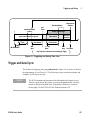
Trigger and Gate Time Line 106
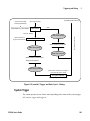
Trigger and Gate Cycle 107
System Trigger 109
Wait-For-Trigger and Triggered States 114
Measurement Gate 117
Gate Set Up 117
Frequency Measurements 119
Enabling Gate Signals on the ‘Gate In/Out’ BNC 125
53210A User’s Guide
7
Contents
6
53210A Math, Graphing, and Data Logging 127
Math Functions 128
Enabling the CALCulate1 Subsystem 129
Smoothing Data 130
Scaling Functions 131
Statistics 139
Limit Checking 143
Histograms 147
Viewing Histograms 148
Histogram Configuration 149
Trend Charts 160
Viewing Trend Charts 161
Data Logging 166
7
Formats and Data Flow 173
Reading Formats and Data Flow 174
Specifying a Format 175
Setting the Block Transfer Byte Order 175
Data Flow 176
Counter File System 183
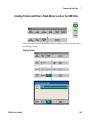
Creating Folders and Files in Flash Memory and on the USB Drive 185
User-Defined Power-On States 194
Managing Folders and Files 197
8
Instrument Status 203
Keysight 53210A Status System 205
Questionable Data Register Group 205
Standard Operation Register Group 206
Standard Event Register 208
Status Byte Register 209
8
53210A User’s Guide
Contents
A
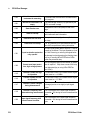
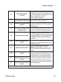
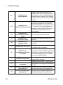
Error Messages 211
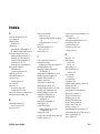
Index 223
53210A User’s Guide
9
Contents
10
53210A User’s Guide
Keysight 53210A 350 MHz RF Counter
User’s Guide
1
Preparation for Use
Front and Rear Panel Overview 13
Front Panel 13
Rear Panel 14
Display 14
About the Instrument 15
Materials Included 15
Operating and Storage Environments 17
Electrical Requirements 17
Applying Power 18
Power-On LED Status 18
Standby Power 19
Battery Operation 20
Battery Care 22
Using Built-In Help 23
Utility Functions 23
Display Configuration 23
User Interaction 26
Reference Settings 28
How the User’s Guide is Organized 32
Welcome. This user’s guide contains configuration and operating information for
the Keysight 53210A 350 MHz RF Counter.
The 53210A is a 2U, 1/2-module width LXI Class C instrument. The 2U, 1/2-module
width references refer to the 53210A’s physical size relative to standard EIA rack
cabinet dimensions. LXI, an acronym for LAN eXtensions for Instrumentation, is an
instrumentation standard for devices that use the Ethernet (LAN) as their primary
remote communications interface.
1
Preparation for Use
53210A
Agilent
350 MHz
RF Counter
A
B
C
Measure
View
System
Auto
Scale
Digits
Freq
H
Graph
Utility
6
5
4
Math
Period
Help
8
7
9
Data
Log
Ratio
.
Shift
0
Gate
+/-
2
Channel / Setup
1
!
Trigger
G
Preset
3
2
1
*
Back
Local
D
1 Watt Max into 50W
E
F
A
Opt 201
Ext Ref In
Ch 2 (53220A/53230A Only)
Gate In/Out
GP-IB
Opt 010 UOCXO
Opt 300 Battery
Opt 150 sw
Opt 106/115
N10149
IECS / NMB-001
Ch 1
(53230A Only)
B
Int Ref Out
Trig In
C
USB
LAN
Line
100-240V, 50-60 Hz
100-127V, 400 Hz
90VA Max
Intertek
ISM 1-A
D
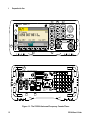
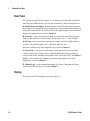
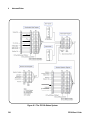
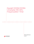
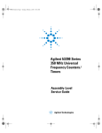
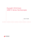
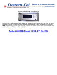
Figure 1-1. The 53210A Universal Frequency Counter/Timer.
12
53210A User’s Guide
Preparation for Use
1
Front and Rear Panel Overview
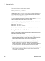
Figure 1-1 shows the front and rear panels of the Keysight 53210A 350 MHz RF Counter.
Front Panel
The shaded areas of the front panel represent keys that perform similar functions. These
areas are briefly described below.
A. Measure Keys - display soft key menus from which the measurement function is
selected. Auto Scale senses the input signal (greater than 100 Hz) on input channel 1, 2,
or 3 and automatically sets the range and input threshold required to make the selected
measurement. Counter measurements are covered in Chapter 3.
B. View Keys - select how measurement data is displayed on the front panel. Display
configuration is covered later in this chapter. Graphics, math, and data logging are
covered in Chapter 6.
C. System Keys - provide instrument-wide configuration which includes setting the
counter preset state and access to utility functions and to the counter’s built-in help
system. For measurement configuration involving numeric entry, Shift changes the key
definitions to the numbers at the lower left of the keys.
D. Channel Keys - select the input channel and displays the soft key menu used to
configure the input signal path. Note that Figure 1-1 includes Channel 3 Option 106 /
115. Signal path configuration is covered in Chapter 4.
E. Gate and Trigger Keys - select the gating and triggering soft key menus used to
control the measurement. Gating and triggering are covered in Chapter 5.
F. Soft Keys - are the menus from which the counter is configured. The menus and soft
keys themselves are defined by the “functional” keys described above.
G. Power/Standby Button - switches the instrument between ‘on’ and ‘off’, or between
‘on’ and ‘standby’.
Standby power (when enabled) is provided by the line voltage or Battery Option 300 and
is used to maintain the temperature of the oven-controlled crystal oscillator (OCXO) Option 010. See “Applying Power” in this chapter for more information.
H. USB ‘Host’ Port - available for transferring measurement data and instrument
configurations between the counter and a USB storage device. The front panel port is for
information transfer only. The rear panel USB port is used for instrument (I/O) control.
Data flow is covered in Chapter 7.
53210A User’s Guide
13
1
Preparation for Use
Rear Panel
The 53210A rear panel shown in Figure 1-1 includes product Option 201 (parallel rear
panel input) and GPIB interface. The rear panel terminals are briefly described below.
A. Parallel Rear Panel Inputs - product Options 201 and 202 add a parallel input on
the rear panel. Note that this IS NOT a separate input. Signals on the center conductor of
either panel’s channel BNC are ALSO present on the opposite panel’s center conductor.
Signal path configuration is covered in Chapter 4.
B. Ext Ref In - is the connector for providing an external reference oscillator signal.
Valid external refererence oscillator (time base) frequencies are 1, 5, and 10 MHz.
Int Ref Out - is the connector for accessing the counter’s internal 10 MHz reference
oscillator. The oscillator signal is a 0.5 Vrms (into 50Ω) sine wave.
Reference oscillator usage and configuration are covered in Chapter 3.
C. Gate In/Out - is an input for external gate signals, and an output for routing the
counter’s internal gate to other devices. Additional information on this connector is
covered in the section “Enabling Gate Signals on the ‘Gate in/Out’ BNC” in Chapter 5.
Trig In - is the connector for supplying an external trigger signal to the counter.
Triggering is covered in Chapter 5.
D. USB and LAN - are the standard input/output (I/O) ports. Configuration of these
ports and the GPIB interface is covered in Chapter 2.
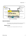
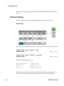
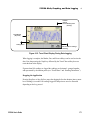
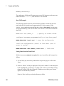
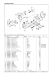
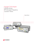
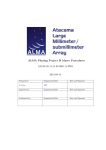
Display
The layout of the 53210A display is shown in Figure 1-2.
14
53210A User’s Guide
Preparation for Use
Status Indicators
Input Settings
10%
AC
1MW
5V
Probe
BW
1
RMT: remote (LAN, USB, GPIB) operation
ExtRef: external frequency reference
: measurement start edge
: trigger threshold
: input coupling (ac or dc)
: input Impedance (1MW, 50W)
: input Range (5V, 50V, 500V)
: probe enabled
: bandwidth filter enabled
ExtRef : invalid external reference
ExtTrig: external trigger source
Battery charge status
Ch. 1
Battery status:
charge level
black – user disabled
red – software disabled
Channel Configuration
Gate
Channel and Function
Main Measurement
Main Measurement Display
Secondary Measurements
Data Entry Area
Soft Keys
Softkey Navigation
Figure 1-2. The 53210A Display.
About the Instrument
This section lists the accessories shipped with the 53210A and contains information on
its specified operating and storage environments and electrical requirements.
Materials Included
The following accessories are shipped standard with the 53210A counter:
53210A User’s Guide
15
1
Preparation for Use
1 Power cord
2 USB cable
3 Keysight I/O Libraries Suite CD-ROM
4 Keysight 53210A/53220A/53230A Product Reference CD-ROM
Additionally, your instrument may have shipped with one or more of the following
options installed.
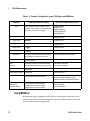
Table 1-1. 53210A Product Options.
Opt. 010: Ultra High-Stability OCXO Timebase
Opt. 106: 6 GHz Microwave Input (Ch. 2)
Opt. 115: 15 GHz Microwave Input (Ch. 2)
Opt. 201: Add parallel Channel 1 input on rear panel
Opt. 202: Install Option 106/115 on front panel
Opt. 203: Install Option 106/115 on rear panel
Opt. 300: Internal Lithium Ion Smart Battery and Charger
NOT E
Each of the product options listed in Table 1-1 is available after the original purchase of
the instrument. Refer to the 53210A/53220A/53230A Service Guide (p/n 53220-90010)
for installation instructions for each of these options.
No Manuals?
There are three printed manuals available with the 53210A:
• Keysight 53210A Quick Start Tutorial (p/n 53210-90005)
• Keysight 53210A User’s Guide (p/n 53210-90001)
• Keysight 53210A/53220A/53230A Service Guide (p/n 53220-90010)
53210A Option 0B0 (delete printed manuals) is the default product documentation
option. If Option 0B0 was ordered, only the Quick Start Tutorial and
53210A/53220A/53230A Product Reference CD-ROM are shipped with the instrument.
All manuals are available on the CD. To obtain printed manuals from Keysight, contact
your Keysight representative.
16
53210A User’s Guide
Preparation for Use
1
Operating and Storage Environments
When operating the 53210A counter, note the following environmental specifications:
Environment:
Temperature:
Humidity:
Altitude:
EN61010, Pollution Degree 2; Indoor Locations
0 °C to +55 °C
5% to 80% RH (non-condensing)
up to 3000 meters, or 10,000 feet
When storing the 53210A counter, note the following storage specification:
Temperature: -30 °C to +70 °C
Use care when moving the counter from cold to warm conditions as condensation may
develop. Ensure that any condensation has evaporated and that the counter has thermally
stabilized before turning on the instrument.
Electrical Requirements
The electrical (power) requirements of the 53210A are summarized below.
Power Supply:
CAT I (do not connect to AC mains)
100 to 240V @ 50/60 Hz (-5% to +10%)
100 to 120V @ 400 Hz (+ 10%)
Power Consumption: 90 VA max when power is on or battery
option is charging. 6 VA max during
power off or standby
Line voltage and frequency are sensed at power on and no input power adjustments (e.g.
fuse changes, line voltage selection) are required.
53210A User’s Guide
17
1
Preparation for Use
NOT E
For additional information, refer to the Safety Information pages at the beginning of this
guide. For a complete list of 53210A product specifications, refer to the data sheet
included on the 53210A/53220A/53230A Product Reference CD (p/n 53220-13601), or
on the Web at:
www.keysight.com/find/53210A
Applying Power
Connect the power cord and press the “on/standby” button on the front panel ( ).
During the power-on sequence the counter performs an auto-calibration and self-test
which includes:
• power supply verification
• FPGA test
• front panel verification
• measurement board verification
• channel 2 test (if present)
• Option 300 battery test (300 if present)
NOT E
If the 53210A does not turn on when the on/standby button is pressed, verify
AC power is available to the instrument and that the power cord is securely
connected. If the instrument still does not turn on, the cooling fan is not
audible, or if the front panel display is off when power is applied, return the
unit to Keysight for repair.
Power-On LED Status
The led located under the on/standby button is an indication of the on/off/standby
condition of the instrument. The different conditions are summarized in the table below.
The ‘off’ status is determined by the presence of OXCO Option 010.
18
53210A User’s Guide
Preparation for Use
1
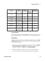
Table 1-2. Power-On LED Status and Color.
Instrument ’Off’
Power Source
Instrument
‘On’
OCXO w/
Standby
enabled
OCXO w/
Standby
disabled
No
OCXO
AC Line
green
amber
off
off
Opt. 300 Battery
(enabled)
green
amber
(blinking)
off
off
Opt. 300 Battery
(disabled)
off
off
off
off
Standby Power
The power modes of the 53210A counter are ‘on’ ‘off’, and ‘standby’. In standby mode
with the instrument connected to line voltage, standby power is supplied to maintain the
temperature within the ultra high-stability oven controlled crystal oscillator (Option
010).
Battery Option 300 itself supplies standby power for the OCXO when the 53210A is not
connected to line voltage.
Refer to “Standby Power to the Reference Oscillator” in Chapter 3 for information on
enabling/disabling standby power.
Cycling Power and Counter Accuracy
With standby power enabled, repeated power cycling (line or battery) does not affect the
standard or ultra-high stability OCXO.
53210A User’s Guide
19
1
Preparation for Use
Battery Operation
WA RNING
During battery operation, the maximum measured signal supplied by the user is +
42V.
Also, connect the instrument chassis to earth ground during battery operation to
minimize shock hazard. Any interruption or disconnection of the protective earth
terminal will cause a potential shock hazard that could result in personal injury.
Under battery power, the instrument chassis may float to the potential of the measured signal supplied by the user.
With Battery Option 300 installed and enabled, the 53210A counter can be operated
using battery power for up to three hours.
Removing AC power when the battery is enabled switches the counter to battery power
automatically with no interruption of operation. Similarly, there is no interruption in the
transition back to line power, provided line power is connected before the battery is
disabled.
Enabling and Disabling the Battery
When using the instrument with the Battery Option 300 for the first time after purchase,
or if the instrument has not been used for an extended period, the battery must be
charged before use. With line power connected and the instrument either on or off,
allow four hours for the battery to reach full charge.
20
53210A User’s Guide
Preparation for Use
1
Battery Option 300 is disabled when the instrument is shipped from the factory. Battery
control (enable/disable) is provided by the front panel keys shown on the previous page
or using the command:
SYSTem:BATTery:ENABle {OFF|ON}
SYSTem:BATTery:ENABle?
(query form)
- ON enables the battery. Off disables the battery. The battery state is stored in
non-volatile memory and does not change when power is cycled or following a reset
(*RST) or instrument preset (SYSTem:PREset or Preset key).
The battery should remain enabled while the counter is using AC power. The battery
should only be disabled if the instrument is stored and unused for an extended period.
This will minimize battery drain.
Reading the Battery Level Pressing the Battery Level soft key or sending the
command:
SYSTem:BATTery:LEVel?
reads the battery charge (in percent) relative to a fully charged (100%) battery.
Battery in Use The presence and status (enabled or disabled) of the battery is
indicated by a battery icon in the upper-right corner of the display (Figure 1-2).
Remotely, the instrument can be queried as to whether it is currently using AC power or
battery power with the command:
SYSTem:BATTery:STATus?
The command returns AC if the instrument is using line power, or BATT if using the
internal battery.
The following table summarizes battery operation:
Operating Time (typ):
Standby Time (typ):
Recharge Time (typ):
Temperature Range:
53210A User’s Guide
3 hours (below +35 °C)
24 hours (below +35 °C, OCXO powered)
4 hours to 100% capacity or 2 hours to 90% capacity
0 °C to +55 °C (operating) - battery charges below +35 °C
-10 °C to +60 °C (storage)
21
1
Preparation for Use
NOT E
If battery operation is in use above the maximum specified operating temperature, the
battery will shut down the instrument to preserve its use. AC power must be applied to
recover from a shut down caused by this condition.
NOT E
For a complete list of battery and all 53210A product specifications, refer to the data
sheet included on the 53210A/53220A/53230A Product Reference CD
(p/n 53220-13601), or on the Web at:
www.keysight.com/find/53210A
Battery Care
When the battery is enabled and the instrument is not connected to AC power, the
battery discharges at 30% of full capacity per day. When the battery is disabled and AC
power is not connected, the battery discharges at 10% of full capacity per month.
When storing the instrument without AC power applied, do not allow the battery to
discharge below 10%. The following equation can be used to determine instrument
storage time without AC power - and still enable the instrument to be fully recharged:
months battery disabled * 10% + days battery enabled * 30%
= 90%
A fully discharged battery may need to be replaced if it has not been recharged for six to
18 months.
22
53210A User’s Guide
Preparation for Use
1
Using Built-In Help
Instrument help is available by pressing and holding any front panel key or softkey.
Pressing the Help key enables you to select additional help topics including front panel
measurement examples.
Utility Functions
Utility functions enable you to configure features of the instrument indirectly related to
measurement selection and configuration. These functions include:
• display configuration - display control and numeric data formatting
• user interaction - localized language selection, audible indicators
• reference settings - time/date, measurement time out, time base, auto-leveling,
53100 series emulation, NISPOM security
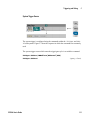
Display Configuration
Measurements can be displayed in numerical or graphical form using the following
keys.
53210A User’s Guide
23
1
Preparation for Use
With AutoDigits On, the number of digits displayed is automatically set based on the
gate time. When Off, the number of digits is set with the rotary knob or [Shift]ed
numeric keys. See “Resolution and Gate Time” in Chapter 5 for more information when
AutoDigits On is set.
When Graph is selected, the data is displayed in a trend chart or histogram. Trend charts
and histograms are covered in Chapter 6.
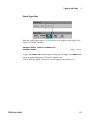
Numeric Format
The format (radix, decimal group separator) of numeric data that appears in the main
measurement display (Figure 1-2) is set using the following keys.
The format also applies to numeric readings within trend charts, histograms, limit
testing, etc.
24
53210A User’s Guide
Preparation for Use
1
Radix The decimal separator (radix point) between the integer and fractional parts of
the reading can be a decimal point (.) or comma (,).
Digit Group Separator A digit group separator between every three digits on either
side of the decimal separator (radix) allows easier viewing of the displayed reading. The
separator can be one of the following:
None - there is no space between digits (e.g. 10.967342515 MHz)
Space - a space is inserted between every three digits (e.g. 10.967 342 515 MHz)
On - a comma (,) or decimal point (.) is inserted between every three digits
depending on the decimal separator (radix) selected.
decimal point radix: 10.967,342,515 MHz
comma radix: 10,967.342.515 MHz
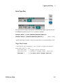
Screen Control
Screen control is available through the keys shown below.
The display screen can be turned off to increase reading throughput and its screen saver
mode can be used to conserve power. Screen brightness can be adjusted for optimal
viewing in different environments.
Note that pressing any key with the display turned off, turns the display back on.
53210A User’s Guide
25
1
Preparation for Use
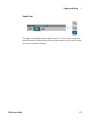
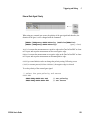
Screen Capture
For documentation of product testing or as a convenience in gathering data, the contents
of the counter display can be captured and saved.
The keys related to this feature are shown below.
The content captured is the display state at the time the [Utility] key is pressed. The file
format is selectable as either bmp ( bitmap file format) or png (portable network
graphics (bitmap) format). Files may be store in internal flash memory or to an external
USB device.
See Chapter 7 for information on selecting paths and creating file names.
User Interaction
The features described in this section are related to the user’s physical interaction with
the instrument.
26
53210A User’s Guide
Preparation for Use
1
Selecting the Instrument ‘Help’ language
Programming messages, context-sensitive help, and other help topics are viewable in six
languages. The selected language remains “active” until changed using the key sequence
shown.
Note that menu soft key labels appear only in English.
Beeper Setting
The counter’s Beeper is an indication of a programming error generated from the front
panel or over the remote interface. Turning off the beeper disables the audio indication.
53210A User’s Guide
27
1
Preparation for Use
Note that the beeper setting does not apply to the tone heard when front panel keys are
pressed.
Reference Settings
Reference settings are counter settings that apply to all counter measurements.
Date and Time
The date and time settings for the counter’s real-time clock are set using the commands:
SYSTem:DATE <year>,<month>,<day>
SYSTem:DATE?
(query form)
SYSTem:TIME <hour>,<minute>,<second>
SYSTem:TIME?
(query form)
The date and time range values are:
year: 2000-2099
month: 1-12
day: 1-31
hour: 0-23
minute: 0-59
second: 0-59.999
The real-time clock is battery-backed and retains the date and time when power is off.
There is no automatic setting of, or automatic return to the current date and time.
28
53210A User’s Guide
Preparation for Use
1
Measurement Time Out
The measurement time-out is the time allowed for each measurement to complete. If a
measurement does not complete before the time out expires, 9.91E37 (not a number)
is returned and the display indication is: - - - - - - -. The sequence continues with the next
reading in the sample count.
Specifying a time out prevents the instrument from pausing indefinitely if for some reason a measurement is unable to complete.
The default and factory-set time out is 1 second. Refer to “Setting the Measurement
Time Out” in Chapter 3 for more information.
Time Base
53210A measurements are based on a reference oscillator - also referred to as an internal/external clock or time base. A valid reference oscillator signal must be present for
measurements to occur.
Refer to “Reference Oscillator Configuration” in Chapter 3 for detailed information on
selecting and configuring the reference oscillator source.
Auto Level
The threshold level is the trigger (input) level at which the counter begins the
measurement. Auto-level is the automatic setting of this threshold based on the positive
and negative peaks of the input signal.
The minimum frequency at which auto-leveling can occur is set as shown.
53210A User’s Guide
29
1
Preparation for Use
Slow sets the minimum frequency for auto-leveling at 50 Hz. Fast sets the minimum
frequency for auto-leveling at 10 kHz.
Refer to “Threshold Level and Sensitivity” in Chapter 4 for additional information on
using auto-level.
Keysight 53100 Series Counter Emulation Mode
The 53210A’s emulation mode enables the Keysight 53181A SCPI command set to
be used with the counter.
30
53210A User’s Guide
Preparation for Use
1
The emulation mode can also be enabled using the command:
SYSTem:LANGuage "<language>"
SYSTem:LANGuage?
(query form)
- language selects the SCPI command set used. Specifying 53181A enables the
emulation mode. Specifying either 53210A disables the mode.
With 53100-series compatibility mode selected, all programming is through the
counter's remote interface (LAN, USB, GPIB). The counter display responds according
to the remote commands received.
Pressing any front panel key while in 53100 compatibility mode returns the counter to
53200 series mode as prompted. Setting or changing to either mode requires the
instrument to be restarted. When updating the instrument firmware “53210A mode”
must be set.
Documentation of the 53181A command set is not provided with this (53210A)
instrument. Usage of this older SCPI command set is discouraged for new use, but is
available for customers who require it.
Securing the Instrument
The 53210A counter can be secured to the National Industrial Security Program
Operating Manual (NISPOM) standard as shown below.
53210A User’s Guide
31
1
Preparation for Use
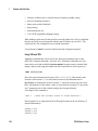
How the User’s Guide is Organized
This user’s guide is written for the operator using the instrument from the front panel,
and for the programmer controlling the counter from a remote (LAN, USB, GPIB)
interface. As such, most topics include a front panel key sequence followed by the
corresponding SCPI commands. For example:
---------------------------------------------------------------------------------------------------------
The input impedance of the 53210A counter can be set to either 50Ω or 1 MΩ using the
command:
INPut[1]:IMPedance {<impedance>|MINimum|MAXimum| DEFault}
INPut[1]:IMPedance? [{MINimum|MAXimum|DEFault}]
(query form)
---------------------------------------------------------------------------------------------------------The description of operation which follows typically applies to both front panel and
remote usage.
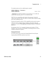
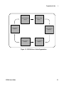
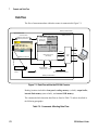
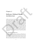
For general reference, the information in this manual is organized as shown in Figure
1-3.
32
53210A User’s Guide
Preparation for Use
Signal Conditioning
Chapter 4
1
Triggering / Gating
Chapter 5
Measurements
Chapter 3
Math and Graphs
Chapter 6
Status Conditions
Chapter 8
Formats / Data Flow
Chapter 7
Figure 1-3. 53210A User’s Guide Organization.
53210A User’s Guide
33
1
34
Preparation for Use
53210A User’s Guide
Keysight 53210A 350 MHz RF Counter
User’s Guide
2
53210A Software Installation and
Interface Configuration
Software Requirements 36
Using the Counter Web-Enabled Interface 37
Connecting the Counter and Viewing its Home Page 37
Web Interface Overview 39
Installing the Keysight IO Libraries 41
Installing Instrument Drivers 43
Adding Instruments to the PC Interface 43
Configuring the LAN Interface 44
Configuring the USB Interface 49
Configuring the GPIB Interface 52
Using Interactive IO 55
Firmware and Driver Updates 56
Disabling Calibration Security 56
SCPI Language Emulation Mode 57
Downloading and Installing the Update Utility 57
Downloading the Firmware Update 58
Installing the Firmware Update 58
Downloading IVI-COM Driver Updates 61
This chapter contains information on IO libraries, drivers, and interfaces used to
program the 53210A from selected development environments. The chapter includes an
introduction to using the counter’s web-enabled interface and provides information on
updating the instrument firmware.
2
53210A Software Installation and Interface Configuration
Software Requirements
The environments available to program the 53210A are dependent upon the IO libraries
and drivers installed. The IO software included with the 53210A is contained on the following CD:
•
Keysight Automation-Ready CD: Keysight IO Libraries Suite
The IVI-C and IVI-COM drivers for the instrument can be found on the web at:
www.keysight.com/find/53210A
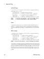
Table 2-1 summarizes the environments, IO driver recommendations, and the location
(media) where specific drivers and libraries can be found.
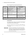
Table 2-1. 53210A Development Environments and Drivers.
IO Driver Recommendations
Interface
Development Environment
LAN
Web-enabled instrument interface
> SCPI Command Interface window
Java™ -enabled Web browser
(available from www.java.com)
LAN, GPIB, USB
Keysight Connection Expert
> Interactive IO window
Keysight IO Libraries CD*
LAN, GPIB, USB
Microsoft® Visual Studio®
> Visual C++
VISA - Keysight IO Libraries CD*
IVI-C - Web
LAN, GPIB, USB
Microsoft® Visual Studio®
> Visual Basic
VISA-COM - Keysight IO Libraries*
IVI-COM
-Web
LAN, GPIB, USB
Microsoft® Visual Studio® .NET
> C#, C++, Visual Basic
IVI-COM - Web
LAN, GPIB, USB
Keysight VEE
IVI-COM -Web
LAN, GPIB, USB
National Instruments LabVIEW™
53210A native mode driver
IVI-C - Web
LAN, GPIB, USB
National Instruments LabWindows/CVI
IVI-C - Web
* Visit www.keysight.com for the latest version of the Keysight IO Libraries Suite.
36
53210A User’s Guide
53210A Software Installation and Interface Configuration
2
Using the Counter Web-Enabled Interface
Operating the 53210A counter from its Web interface requires a Java-enabled Web
browser but no additional (i.e. user-installed) libraries or drivers. The Web interface
provides access to the counter’s SCPI command set.
NOT E
This section describes the Web pages and windows primarily used to program
the 53210A. Refer to “Help with this Page” associated with each Web page for
additional information on functions or pages not covered in this manual.
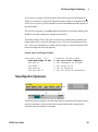
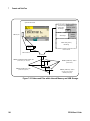
Connecting the Counter and Viewing its Home Page
Connect the counter directly to the PC or to the PC through a network switch using a
standard LAN cable.
Obtaining the IP Address
Turn on the counter and open the Web browser. Allow a few moments for the counter’s
IP address to be assigned (either through DHCP or AUTO IP). The IP address can be
read from the counter front panel as shown.
53210A User’s Guide
37
2
53210A Software Installation and Interface Configuration
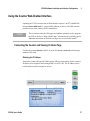
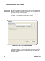
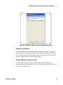
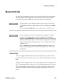
Enter the IP address in the browser’s address window. With “Advanced information ...”
selected, the counter’s Web home page should appear as shown in Figure 2-1.
Browser Configuration
In some network configurations a proxy server may prevent access to the instrument (i.e.
“page cannot be displayed”) after the IP address is entered. In this situation, the proxy
must be configured from the browser such that the proxy is not used for (IP) addresses
within the range of those that can be assigned to the 53210A.
Figure 2-1. The 53210A Web-Enabled Interface ‘Welcome Page’.
38
53210A User’s Guide
53210A Software Installation and Interface Configuration
2
NOT E
For ease in (Internet) browser navigation when controlling multiple instruments, open a
separate browser session for each Web-enabled instrument.
NOT E
Although no additional libraries or drivers are required to use the Web interface, the
interface is also accessible from Keysight Connection Expert (KCE). See “Opening
the Web Interface from Keysight Connection Expert” for more information.
Web Interface Overview
The following information is an introduction to the counter’s Web interface.
The counter welcome page (Figure 2-1) displays IO information, can be used to identify
a connected instrument, and contains menu tabs for accessing additional counter functionality.
To easily identify the counter among other instruments using its Web interface home
page, clicking on:
Turn On Front Panel Identification Indicator
changes the counter display to “LXI Web Identify” until the indicator is turned off by
clicking on:
Turn Off Front Panel Identification Indicator
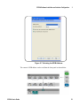
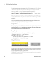
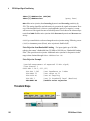
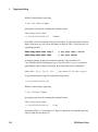
Programming the Counter
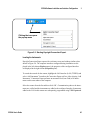
Selecting the ‘Remote Control’ icon (second from top) on the welcome page opens the
Interactive IO window shown in Figure 2-2. From this window, SCPI commands can be
sent to the instrument.
53210A User’s Guide
39
2
53210A Software Installation and Interface Configuration
NOT E
Web interface pages other than the ‘Welcome Page’ may be password protected. When
shipped from the factory no password is set; however, an ‘Enter Password’ dialog box
may appear. Click on the dialog box to continue.
If the page is password protected and the password is unknown, pressing [Utility],
(I/O Config), (LAN Reset) on the front panel clears the password.
Figure 2-2. The Web UI SCPI Command Interface.
Any command in the counter’s SCPI command set can be sent to the instrument. Query
commands which include ‘?’ in the syntax return data and can be sent by selecting Send
& Read after the command is entered. Commands which do not return data are sent
using Send Command.
40
53210A User’s Guide
53210A Software Installation and Interface Configuration
2
Changing LAN Settings and Using Password Protection
The Network Configuration Page icon provides access to the counter’s LAN settings,
and enables you to set a password to prevent unauthorized access to the Web instrument
interface. Select Modify Configuration to change and save settings.
Installing the Keysight IO Libraries
The Keysight IO Libraries include the VISA and VISA-COM libraries used for
programming the 53210A in Microsoft® development environments (Table 2-1). The
VISA and VISA-COM libraries allow you to send commands from the 53210A SCPI
command set to the instrument. The IO libraries also include Keysight Connection
Expert described and used later in this chapter.
NOT E
The Keysight IO Libraries (VISA and VISA-COM) must be installed prior
to installing any other I/O drivers (e.g. IVI-C, IVI-COM).
NOT E
The Keysight IO Libraries and utilities are often updated to include
additional features and improve usability. The figures used in this chapter
represent the latest version of the IO Libraries available at the time of
printing. While you may have a different version, the process of configuring
and adding instruments to an interface remains basically the same.
The IO Libraries are contained on the Keysight Automation-Ready CD or may be
downloaded from the Electronic Test & Measurement Software page at:
http://www.keysight.com
Before installing the IO libraries, review Table 2-2 to verify that your computer meets
the specifications required for the latest version of the software.
53210A User’s Guide
41
53210A Software Installation and Interface Configuration
2
Table 2-2. Keysight IO Libraries Suite System Requirements.
Windows XP (SP 3 or later)
Operating System
Processor
Available Memory
600 MHz or higher required
800 MHz recommended
1 GHz 32-bit (x86)
1 GHz 64-bit (x64)
256 MB minimum
1 GB or greater recommended
1 GB minimum
Available Disk Space 1.5 GB
* 1 GB recommended for Microsoft .NET
Framework 2.0 SP2
* 65 MB for Keysight IO Libraries Suite
Video
Web Browser
Windows Vista /Windows 7
32/64-bit editions
1.5 GB
* 1 GB recommended for Microsoft
.NET Framework 2.0 SP1
* 65 MB for Keysight IO Libraries Suite
Super VGA (800x600) w/ 256 colors or more
Support for DirectX 9 graphics w/128 MB
graphics memory recommended
(Super VGA graphics is supported.)
Microsoft Internet Explorer 6.0 or greater
Microsoft Internet Explorer 7 or greater
Note: because of the installation procedure, less memory may be required for operation than for installation.
Loading the Software
Close all applications on your computer. Insert the Keysight Automation-Ready CD
into the CD drive. Follow the instructions as prompted for a typical installation.
Accept all default directories specified if prompted.
If the IO libraries installation does not start automatically, select Start > Run from the
Windows start menu and type <drive>:\autorun\auto.exe where <drive> is the designator of the CD drive.
NOT E
42
If another vendor’s implementation of VISA (Virtual Instrument Software
Architecture) is currently installed on your computer, continue installation of
the Keysight IO Libraries by installing Keysight VISA in side-by-side mode.
More information on side-by-side operation can be found in IO Libraries Suite
Help (available after installation is complete) under “Using Keysight’s and
Other Vendors’ Products Together.”
53210A User’s Guide
53210A Software Installation and Interface Configuration
2
After the IO libraries have been installed, close the installation wizard. If applicable,
continue with instrument driver installation as described below. Otherwise, continue
with the ”Adding Instruments to the PC Interface” section of this chapter.
Installing Instrument Drivers
Interchangeable Virtual Instrument (IVI) drivers (when available) are used for programming the 53210A with Keysight VEE, with National Instruments® LabVIEW , or in
Microsoft® development environments.
Install the appropriate driver based on the development environment you are using
(Table 2-1). Accept all default directories specified during installation if prompted.
Setup type “Typical” is applicable for most users.
NOT E
Installing the Keysight IO Libraries installs the Interchangeable Virtual
Instrument (IVI) Shared Components. The IVI Shared Components are
required before the IVI drivers (e.g. IVI-COM, IVI-C)can be installed.
Adding Instruments to the PC Interface
During installation of the Keysight IO Libraries, the IO interfaces (LAN, USB, GPIB)
detected on the PC are configured. This section contains information for programmatically adding the 53210A to those interfaces using the Keysight IO Libraries
‘Connection Expert’ utility.
Simultaneous LAN/USB/GPIB connections to the instrument are allowed.
NOT E
53210A User’s Guide
The figures used in this chapter represent the latest version of the IO Libraries
available at the time of printing. While you may have a different version, the
process of configuring and adding instruments remains basically the same.
43
2
53210A Software Installation and Interface Configuration
Remote Interface Configuration
The following sections cover front panel configuration of the LAN, USB, and GPIB
interfaces. The interfaces can also be configured programmatically using the ‘Remote
Interface Configuration’ commands in the SCPI SYSTem subsystem. This subsystem,
plus descriptions of all SCPI commands, is located in the ‘Programming Reference’ section of the 53210A/53220A/53230A Product Reference CD.
Configuring the LAN Interface
With the counter connected to the LAN interface, the IP address can be read from the
front panel as follows.
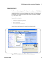
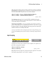
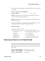
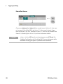
Once the IP address is known, start the Connection Expert utility by clicking the
‘Keysight IO Control’ icon and selecting “Keysight Connection Expert” from the pop
up menu as shown in Figure 2-3.
44
53210A User’s Guide
53210A Software Installation and Interface Configuration
2
Clicking the icon opens
the pop-up menu
Figure 2-3. Starting Keysight Connection Expert.
Locating the Instruments
Keysight Connection Expert opens with a welcome screen and window similar to that
shown in Figure 2-4. The computer interfaces configured during installation are displayed in the left column (Explorer pane), the properties of the configured interface
are displayed in the right column (Properties pane).
To search the network for the counter, highlight the LAN interface (LAN (TCPIP0)) and
select “Add Instrument” located on the Connection Expert tool bar. After selecting ‘Add
Instrument’, Connection Expert performs an automatic find (Auto Find) of all instruments on the same subnet as the computer.
Select the counter from the list and then click ‘OK’. Communication paths to the instruments are verified and the instruments are added to the configured interface. Instruments
added to the LAN in this manner are subsequently programmed using VXI-11 protocol.
53210A User’s Guide
45
2
53210A Software Installation and Interface Configuration
53210A (GPIB0::3::INSTR)
53210ACounter
configured interfaces
Figure 2-4. Keysight Connection Expert Interface Window.
Using the Sockets Protocol
For higher performance, instruments added to the LAN
configuration can also use the Sockets protocol. To use this connection, select ‘Add
Address’ from the ‘Add Instruments’ menu (Figure 2-4). In this window, enter the
instrument’s host name or IP address and under ‘Optional Socket Connection’, select
‘Use socket connection’ (Figure 2-5). Note that an instrument can have both VXI-11
and Sockets connections in the configuration (Figure 2-4).
46
53210A User’s Guide
53210A Software Installation and Interface Configuration
2
A-53210A-00050
enter and select to add
Socket connection
Figure 2-5. Adding a Sockets Connection.
About IP Addresses and Host Names
Dynamic Host Configuration Protocol (DHCP) and Automatic IP are enabled on the
53210A when shipped from Keysight. This allows the instrument to automatically
obtain an address on the network. If there is a DHCP server on the network, the server
will assign the address to the instrument.
If there is not a DHCP server on the network, the 53210A will automatically determine
the address to use. The address will be in the range 169.254.1.1 to 169.254.255.255.
53210A User’s Guide
47
2
53210A Software Installation and Interface Configuration
Host Names
The 53210A has a default host name. The format of the host name is:
A-53210A-nnnnn
where ‘nnnnn’ are the last five digits of the instrument’s serial number.
The instrument host name is reported by Connection Expert for network servers that
support Dynamic Domain Name Service (DNS). For network servers that do not support
Dynamic DNS, only the IP address is reported.
Instrument Addressing
During programming, the 53210A is accessed through its
address string which consists of an IP address:
TCPIP0::169.254.2.30::inst0::INSTR
TCPIP0::169.254.2.30::5025::SOCKET
(VXI-11)
(Sockets)
or host name:
TCPIP0::A-53210A-00050.keysight.com::inst0::INSTR
48
53210A User’s Guide
53210A Software Installation and Interface Configuration
2
Disabling the LAN Interface
The LAN interface can be disabled from the front panel by selecting I/O Config followed by LAN Off and cycling power on the instrument. When disabled, the interface
cannot be configured by the Connection Expert utility.
Opening the Web Interface from Keysight Connection Expert
The LAN interface is the only IO interface from which the counter’s Web-enabled user
interface can be accessed. To open the Web UI, highlight the configured LAN instrument (Figure 2-4) and select “Instrument Web Interface...” from the Connection Expert
window.
Configuring the USB Interface
The 53210A is a high-speed USB 2.0 device. Connection to the instrument is through
the Type B USB connector located on the instrument rear panel.
NOT E
The first time the 53210A is connected to the PC via the USB cable, a
“hardware wizard” utility within the PC may start and prompt you for
installation software for the product. There is no installation software for the
USB interface other than the libraries on the Keysight Automation-Ready CD
that ships with the 53210A. Continue through the “wizard” application without
searching for software and using the default selections.
Adding Instruments to the USB Configuration
With the 53210A and PC connected through the USB cable, start Keysight Connection
Expert (Figure 2-4) if it is not already open. The PC should detect the presence of the
USB device. If necessary, right-click the USB interface (USB0) and then select
“Refresh This Interface”.
Connection Expert will attempt to establish a communication path to the instrument. If
successful, the instrument will be added to the list of USB
configured instruments (Figure 2-4). The USB address can be read from the front panel
as shown below.
53210A User’s Guide
49
2
53210A Software Installation and Interface Configuration
The USB Address String
When programming the 53210A over USB, the instrument’s USB address is included in
the address string as follows:
USB0::2391::1287::0123456789::0::INSTR
To simplify addressing during programming, a VISA alias can be assigned and used in
place of the complete address. To assign an alias from Connection Expert, right-click on
the default alias name and then select “Change Properties”. Enter the alias and then
select ‘OK’ (Figure 2-6).
50
53210A User’s Guide
53210A Software Installation and Interface Configuration
2
53210ACounter
Figure 2-6. Setting a VISA Alias for the USB Address String.
Disabling the USB Interface
The USB interface can be disabled from the front panel by selecting I/O Config, followed by USB Settings, and then USB Off. When disabling or enabling the USB interface, you must cycle power for the change to take affect. When disabled, the interface
cannot be configured by the Connection Expert utility.
Using the USB Interface with Interactive IO
The Web-enabled instrument interface is not available from the USB interface.
An alternate programming method is to use the Connection Expert ‘Interactive IO’ utility (see “Using Interactive IO).
53210A User’s Guide
51
2
53210A Software Installation and Interface Configuration
Configuring the GPIB Interface
NOT E
The following information assumes a GPIB card or USB/GPIB interface is
present on your computer.
Programming access to the 53210A is also available through the GPIB interface. GPIB
cables can be connected to the PC in a “star” (all cables connect directly to the computer) or “linear” (instrument to instrument) configuration.
Adding Instruments to the GPIB Configuration
To add instruments to the GPIB interface, highlight GPIB0 and select “Add Instrument”
on the Connection Expert tool bar (Figure 2-4). In the ‘New GPIB Instrument’ window
that appears (Figure 2-7), select the counter’s GPIB address (note: factory-set address
= 3) and select ‘OK’.
Connection Expert will attempt to establish a communication path to the instrument. If
the counter is at the address specified, the instrument will be added to the list of
GPIB-configured instruments.
52
53210A User’s Guide
53210A Software Installation and Interface Configuration
2
Figure 2-7. Selecting the GPIB Address.
The counter’s GPIB address can be read from the front panel as shown below.
53210A User’s Guide
53
2
53210A Software Installation and Interface Configuration
The GPIB Address String
When programming the counter over GPIB, the instrument’s GPIB address is included
in the address string as shown below:
GPIB0::3::INSTR
Changing the GPIB Address
To change the GPIB address, select GPIB Address and using the rotary knob or Shifted
numeric keys, set the desired address. Once the address is changed, you must cycle
power for the change to take affect.
If the GPIB address is changed, the new address IS NOT updated in Connection Expert
interface window (Figure 2-4).
From the (Connection Expert) window, highlight the GPIB instrument and then select
‘Change Properties ...”. Within the configurable properties window (Figure 2-7), change
the address to the new address setting and select ‘OK’.
Disabling the GPIB Interface
The GPIB interface can be disabled from the front panel by selecting I/O Config, followed by GPIB Settings, and then GPIB Off. When disabling or enabling the interface
you must cycle power for the change to take affect. When disabled, the interface cannot
be configured by the Connection Expert utility.
Using the GPIB Interface with Interactive IO
The Web-enabled instrument interface is not available from the GPIB interface. An
alternate programming method is to use the Connection Expert ‘Interactive IO’ utility
(see “Using Interactive IO).
54
53210A User’s Guide
53210A Software Installation and Interface Configuration
2
Using Interactive IO
The Connection Expert ‘Interactive IO’ utility provides another method (Table 2-1) of
sending commands to the 53210A. Interactive IO is accessible from any of the PC’s IO
interfaces, and allows you to send any command in the 53210A SCPI command set to
the instrument. You can also choose from a menu of IEEE-488 Common commands
(e.g. *IDN?, *RST, *TST?).
Interactive IO can be used to:
•
troubleshoot communication problems
•
issue a “device clear”
•
learn the instrument's command set
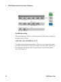
Figure 2-8 shows how Interactive IO is started for a selected interface.
select Interactive IO
53210A (GPIB0::3::INSTR)
53210ACounter
highlight interface
Figure 2-8. Starting Interactive IO for a Selected Interface.
53210A User’s Guide
55
2
53210A Software Installation and Interface Configuration
NOT E
If the Interactive IO window is used to send the self-test (*TST?) command to
the 53210A, the “timeout” period may have to be increased to allow the results
to be returned. This is done using the ‘Options’ tab on the Interactive IO
window. The 53210A self-test takes approximately seven seconds to complete.
Firmware and Driver Updates
Firmware and driver updates (when available) for the 53210A are available via the Web.
This section contains information for locating and downloading the updates to your
computer, and then installing the updates in the instrument.
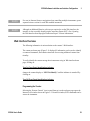
Disabling Calibration Security
Before firmware updates can be installed, the counter’s calibration security feature must
be disabled. This done using the command:
CALibration:SECurity:STATe {OFF|ON}, <code>
CALibration:SECurity:STATe?
(query form)
To unsecure the instrument, you must provide the security code in addition to setting the
state to OFF. The security code is set to AT53210A when the instrument is shipped
from the factory. Note, however, the security code may have been changed once the
counter has been in use.
After the firmware update is complete, the counter can be re-secured by setting the state
to ON and providing the security code. The calibration count is unaffected when changing the security state or by a firmware update.
The calibration count can be read with the command:
CALibration:COUNt?
56
53210A User’s Guide
53210A Software Installation and Interface Configuration
2
SCPI Language Emulation Mode
If the 53210A is sometimes used in 53181A SCPI language (emulation) mode, the
instrument must be returned to its original (53210A) mode before the firmware can be
updated.
Downloading and Installing the Update Utility
53210A firmware updates are installed in the instrument using the Keysight firmware
update utility. The utility and firmware update can be found on the Web at:
www.keysight.com/find/53210A
Once this page is displayed, select the ‘Technical Support’ tab and then select ‘Drivers
& Software’. Click on ‘532x0A Firmware Update’ and under ‘Documents & Downloads’ select the utility:
53210A/53220A/53230A Firmware Update Utility
When prompted, select ‘Run’ to install the utility. The default installation directory is
C:\Program Files\Keysight\Firmware Update Utility Type 2. The utility will also be
added to the ‘start’ menu under “Keysight”.
53210A User’s Guide
57
2
53210A Software Installation and Interface Configuration
Downloading the Firmware Update
Return to the Web page and under ‘Documents & Downloads’ select:
532x0A Firmware Update Revision <revision number>
When prompted, select ‘Run’ to download (save) the file to your PC. Note the directory
location as you will need to specify the path to the firmware file when you run the
update utility.
NOT E
Firmware updates are available from the LAN interface only. Note the IP
address before starting the utility.
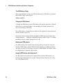
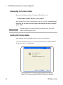
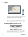
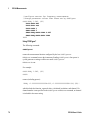
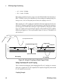
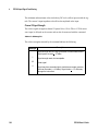
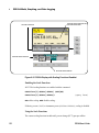
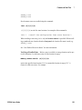
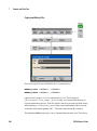
Installing the Firmware Update
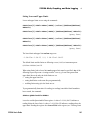
After the update file is downloaded from the web site it can be installed.
1. From the installation directory or ‘start’ menu, start the utility. A window similar to
that shown in Figure 2-9 should appear.
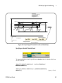
Figure 2-9. Firmware Update Utility File Selection Window.
58
53210A User’s Guide
53210A Software Installation and Interface Configuration
2
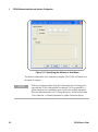
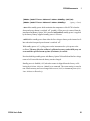
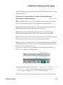
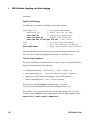
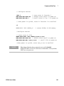
2. Press Next and using the Browse button, specify the path to the firmware file (Figure
2-10). Once specified, the instrument model number will appear in the ‘Applicable
Models’ window along with the revision and instrument description. Select Next.
Figure 2-10. Selecting the Update File Path.
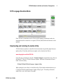
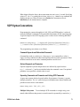
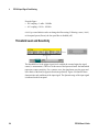
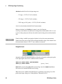
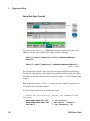
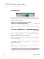
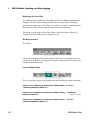
3. Enter the counter’s IP address or host name (Figure 2-11). Select ‘Update’ to start the
update process.
53210A User’s Guide
59
2
53210A Software Installation and Interface Configuration
Figure 2-11. Specifying the Address or Host Name.
The firmware update takes a few moments to complete. The 53210A will reboot once
the update is complete.
NOT E
60
Following a firmware update, Keysight Connection Expert (if running) may
report that the 53210A configuration has changed. This is represented by a
yellow triangle and an exclamation point (!) next to the updated instrument.
Select the instrument name, select ‘Change Properties’, and then select either
‘Test Connection’ or ‘Identify Instrument’ to update Connection Expert.
53210A User’s Guide
53210A Software Installation and Interface Configuration
2
Downloading IVI-COM Driver Updates
IVI-COM and LabVIEW drivers for the 53210A (when available) are provided on the
Web at:
www.keysight.com/find/53210A
Once this page is displayed, select the ‘Technical Support’ tab and then select ‘Drivers
and Software’. The drivers and associated ‘readme’ files are located within this list.
53210A User’s Guide
61
2
62
53210A Software Installation and Interface Configuration
53210A User’s Guide
Keysight 53210A 350 MHz RF Counter
User’s Guide
3
53210A Measurements
Counter Measurement Summary 64
Reference Oscillator Configuration 64
Reference Oscillator Source 65
Standby Power to the Reference Oscillator (Option 010)
Setting the Measurement Time Out 70
SCPI Syntax Conventions 71
The MEASure and CONFigure Commands 73
Using MEASure 74
Using CONFigure 75
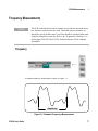
Frequency Measurements 77
Frequency Ratio Measurements 79
Period Measurements 81
68
This chapter contains general programming information and examples of the measurements that can be made with the 53210A counter.
3
53210A Measurements
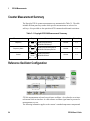
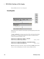
Counter Measurement Summary
The Keysight 53210A counter measurements are summarized in Table 3-1. The table
includes the front panel keys under which specific measurements are selected via
soft-keys. Also provided are the equivalent SCPI commands and channel restrictions.
Table 3-1. Keysight 53210A Measurement Summary
Instrument
Channels
CONFigure:FREQuency
MEASure:FREQuency?
53210A
1,2
CONFigure:FREQuency:RATio
MEASure:FREQuency:RATio?
53210A
1,2
CONFigure:PERiod
MEASure:PERiod?
53210A
1,2
Measurement
Key
Command
Frequency
Freq
Frequency Ratio
Ratio
Period
Period
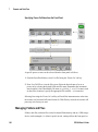
Reference Oscillator Configuration
53210A measurements are based on a reference oscillator - also referred to as an internal/external clock or time base. A valid reference oscillator signal must be present for
measurements to occur.
The following information applies to the counter’s standard temperature compensated
64
53210A User’s Guide
53210A Measurements
3
crystal oscillator (TCXO) and Option 010 Ultra High-Stability oven-controlled crystal
oscillator (OCXO) references.
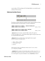
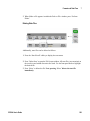
Reference Oscillator Source
The reference oscillator (time base) is either the counter’s internal oscillator or the internal oscillator tuned to an external reference. The source commands are:
[SENSe:]ROSCillator:SOURce {INTernal|EXTernal}
[SENSe:]ROSCillator:SOURce?
(query form)
[SENSe:]ROSCillator:SOURce:AUTO {OFF|ON}
[SENSe:]ROSCillator:SOURce:AUTO?
(query form)
- INTernal selects the counter’s internal 10 MHz oscillator. The signal is a
0.5 Vrms (into 50Ω) sine wave. The internal oscillator signal is also present on the counter’s rear panel Int Ref Out connector.
- EXTernal selects an external reference signal applied to the rear panel
Ext Ref In connector. The signal must be:
•
1 MHz , 5 MHz, or 10 MHz
•
100 mVrms to 2.5 Vrms
•
sine wave
and the frequency must be specified by the SENSe:ROSCillator:EXTernal:FREQuency command.
- :AUTO ON enables automatic selection of the reference oscillator source. If a 1, 5, or
10 MHz signal is present on the counter’s Ext Ref In connector, source EXTernal is
set. If a valid signal is not present or is lost, the source automatically switches to
53210A User’s Guide
65
3
53210A Measurements
INTernal.
Note that specifying an oscillator source (INTernal or EXTernal) using
[SENSe:]ROSCillator:SOURce disables automatic selection.
- :AUTO Off disables automatic selection of the oscillator source. The source is then
set by the [SENSe:]ROSCillator:SOURce command.
The reference oscillator source is set to INTernal with automatic selection enabled
(On) when the counter is shipped from the factory or following the SYSTem:SECure:IMMediate command. Settings are stored in non-volatile memory and
are not changed after a reset (*RST) or instrument preset
(SYSTem:PREset or Preset key).
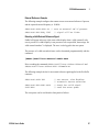
Specifying the External Reference Frequency
When the reference oscillator source is EXTernal as set by either SENSe:ROSCillator:SOURce or SENSe:ROSCillator:SOURce:AUTO, the lock frequency of
the external signal (to which the internal oscillator is tuned) must be indicated using the
command:
[SENSe:]ROSCillator:EXTernal:FREQuency {1E6|5E6|10E6|
MINimum|MAXimum|DEFault}
[SENSe:]ROSCillator:EXTernal:FREQuency? [{MINimum|MAXimum|
DEFault}]
(query form)
The external reference frequency setting is 10 MHz when the counter is shipped from
the factory or following the SYSTem:SECure:IMMediate command. The setting is
stored in non-volatile memory and is not changed after a reset (*RST) or instrument preset (SYSTem:PREset or Preset key).
66
53210A User’s Guide
53210A Measurements
3
External Reference Example
The following example configures the counter to tune to an external reference if present,
and the expected external frequency is 10 MHz.
SENS:ROSC:SOUR:AUTO ON // tune to external ref if present
SENS:ROSC:EXT:FREQ 10E6
// signal will be 10 MHz
Detecting a Valid External Reference Signal
ExtRef will appear in the top, right corner of the display when a valid (external) reference is present. If a valid frequency is not present or was not specified, the message “No
valid external timebase” is displayed. The error is also logged in the error queue.
The presence of a valid external reference can be determined programmatically with the
command:
[SENSe:]ROSCillator:EXTernal:CHECk ONCE
Prior to sending the command, SENSe:ROSCillator:SOURce EXTernal and
SENSe:ROSCillator:SOURce:AUTO OFF must be set.
The following example checks for an external reference signal applied to the Ext Ref In
connector.
SENS:ROSC:SOUR EXT
SENS:ROSC:EXT:CHEC ONCE
SYST:ERR?
//
//
//
//
set source, also disables
automatic source selection
check for valid signal
read the error queue
The error queue can be read from the front panel as follows:
53210A User’s Guide
67
3
53210A Measurements
The status of the external reference (time base) is also monitored by the counter’s Questionable Data register. The register can be queried with the command:
STATus:QUEStionable:EVENt?
A value of +1024 (bit 10) indicates an invalid frequency (time base) error. Reading the
register clears all bits in the register. See Chapter 8 for information on the counter’s status system.
Standby Power to the Reference Oscillator (Option 010)
Standby power to maintain the operating temperature of the counter’s internal OCXO
reference oscillator (Option 010) is provided by the the line voltage or from Battery
Option 300. Standby power is enabled and disabled using the command:
68
53210A User’s Guide
53210A Measurements
3
[SENSe:]ROSCillator:INTernal:POWer:STANdby {OFF|ON}
[SENSe:]ROSCillator:INTernal:POWer:STANdby?
(query form)
- On enables standby power which maintains the temperature of the OCXO when the
front panel power button is switched ‘off’ (standby). If line power is removed from the
instrument and Battery Option 300 is installed and enabled, standby power is supplied
by the battery. Battery-supplied standby power is 24 hours.
-Off disables standby power from either the line voltage or battery to the internal oscillator when the front panel power button is switched ‘off’.
With standby power Off, cycling power on the instrument also cycles power to the
oscillator. This may affect the oscillator’s calibrated accuracy, and stability may not
occur until the specified warm-up time (45 minutes) is reached.
Note that disabling standby power with Battery Option 300 installed and the line voltage
removed will extend the time the battery remains charged.
Standby power is disabled (Off) when the counter is shipped from the factory or following the SYSTem:SECure:IMMediate command. The current setting is stored in
non-volatile memory and is not changed after a reset (*RST) or instrument preset (SYSTem:PREset or Preset key).
53210A User’s Guide
69
3
53210A Measurements
Setting the Measurement Time Out
The measurement time-out is the time allowed for each measurement to complete. If a
measurement does not complete before the time out expires, 9.91E37 (not a number)
is returned and the display indication is: - - - - - - -. The sequence continues with the next
reading in the sample count.
Specifying a time out prevents the instrument from pausing indefinitely if for some reason a measurement is unable to complete.
The measurement time out is set with the command:
SYSTem:TIMeout {<time>|MINimum|MAXimum|INFinity|DEFault}
SYSTem:TIMeout? [{MINimum|MAXimum|DEFault}]
(query form)
- time is the specified time out in the range of 10 ms to 2,000s with 1 ms
resolution. The time out setting can affect reading throughput when multiple readings
are taken during the trigger cycle. Trigger delays, gate times, and gate delays (Chapter 5)
should be considered when setting an optimum time out value.
The time out setting is stored in non-volatile memory and is not changed following a
reset (*RST) or instrument preset (SYSTem:PREset or Preset key).
70
53210A User’s Guide
53210A Measurements
3
When shipped from the factory the measurement time out is set to 1 second. Specifying
a time of 9.9E+37 or sending the SYSTem:SECurity:IMMediate command also
disables the time out. When the time out is disabled, the instrument will wait
indefinitely for the measurement to complete.
SCPI Syntax Conventions
Programming the counters through their LAN, USB, and GPIB interface is achieved
using the Standard Commands for Programmable Instruments (SCPI) control language.
A typical example of the SCPI language syntax is shown for the following MEASure
command:
MEASure:FREQuency? [{<expected>|MINimum|MAXimum|DEFault}
[,{<resolution>|MINimum|MAXimum|DEFault}]][,<channel>]]
The programming conventions are as follows.
Command Keywords and Abbreviated Commands
Command keywords (e.g. MEASure, FREQuency?) are separated by a colon (:).
Upper case letters indicate the abbreviated spelling of the keyword or parameter. Either
the abbreviated form or the entire command/parameter must be used.
Optional Keywords and Parameters
Optional (implied) keywords and parameters are indicated by square brackets
(e.g. [,<channel>]) and are not included when the command is sent. If an optional
parameter is not specified, a default value is used.
Separating Commands and Parameters and Linking SCPI Commands
A space must separate the last keyword and the first parameter. Commas (,) separate
multiple parameters. The ‘@’ symbol must precede each counter channel number and
parentheses must enclose each channel:
MEAS:FREQ:RAT? 5E6,(@2),(@1)
Multiple Subsystems
To send multiple SCPI commands in a single string, commands within different subsystems (root nodes) must be separated by a semicolon (;)
53210A User’s Guide
71
3
53210A Measurements
and a colon (:). For example, the string:
INP:COUP AC;:TRIG:SOUR EXT
requires a semicolon and a colon because the subsystems/root nodes (INPut and TRIGger) are not the same.
Same Subsystem For commands that share the same subsystem, multiple commands
can also be sent in a single string. The first command references the root node, and subsequent commands separated by semicolons, are referenced to the same level as the previous command. As an example, the command sequence representing the
CALCulate2 subsystem:
CALC2:TRAN:HIST:STAT ON
CALC2:TRAN:HIST:POIN 15
CALC2:TRAN:HIST:RANG:AUTO ON
CALC2:TRAN:HIST:RANGe:AUTO:COUNt 300
can be sent in a string as:
CALC2:TRAN:HIST:STAT ON;POIN 15;RANG:AUTO ON;AUTO:COUN 300
Separate Command Lines or Strings? Sending commands in a single string rather
than in separate command lines can eliminate “settings conflict” errors. When sent on
separate lines, the counter checks for errors as each command (line) is parsed. When
sent as a string, the entire string is parsed before error conditions are checked.
Linking IEEE 488-2 Common Commands and SCPI Commands
In a command string containing both IEEE 488.2 common commands (e.g. *RST,
*WAI, *OPC?) and SCPI instrument commands, the common commands are separated
from the SCPI commands by a semicolon (;). An example is shown in the following
string:
CALC:STAT ON;AVER:STAT ON;:INIT;*WAI;:CALC:AVER:AVER?
72
53210A User’s Guide
53210A Measurements
NOT E
3
Information on the SCPI programming conventions is also included in the ‘Programmer’s Reference’ section of the Keysight 53210A/53220A/ 53230A Product Reference CD.
The MEASure and CONFigure Commands
Each time the counter takes a measurement it does so from a configuration
based on multiple parameters. The easiest and most common starting point for setting
these parameters programmatically is using commands within the CONFigure and
MEASure subsystems. These commands are considered “high-level” commands as
multiple counter parameters are set or defaulted from a single command. “Low-level”
commands are those within other subsystems (i.e. INPut, TRIGger, SENSe) that
allow you to change a parameter value from that set, or defaulted to, using CONFigure
or MEASure.
Executing commands from the CONFigure and MEASure subsystems is equivalent to
setting parameters individually using the commands/subsystems shown in Table 3-2.
53210A User’s Guide
73
53210A Measurements
3
Table 3-2. Counter Configuration using CONFigure and MEASure
Low-Level Command/Subsystem
Parameter
CONFigure/MEASure Setting
Input
range, low-pass filtering, coupling, impedance and noise rejection are unchanged from
previous or their power-on settings.
INPut{[1]:RANGe
INPut[1]:FILTer
INPut[1]:COUPling
INPut[1]:IMPedance
INPut[1]:NREJect
Trigger source
IMMediate
TRIGger:SOURce
Trigger slope
NEGative
TRIGger:SLOPe
Trigger delay
0.0 seconds
TRIGger:DELay
Trigger count
1 trigger
TRIGger:COUNt
Sample count
1 sample
SAMPle:COUNt
GATE Source
Based on measurement function specified by
the CONFigure or MEASure command.
SENSe:FREQuency:GATE:SOURce
External Gate Source
Gate In/Out BNC
OUTPut:STATe
Math
Graphics
Disabled, including the individual calculate
functions. Other parameters are unchanged.
CALCulate1 subsystem
CALCulate2 subsystem
Auto-level Frequency
Unchanged
SYSTem:ALEVel:FREQuency
Measurement Timeout
Unchanged
SYSTem:TIMeout
Reference oscillator
Unchanged from previous settings.
SENSe:ROSCillator:SOURce
SENSe:ROSCillator:SOURce:AUTO
SENSe:ROSCillator:EXTernal:FREQuency
Reading Format
Data Storage
Instrument Status
Unchanged from previous settings.
Unchanged from previous settings.
Unchanged from previous settings.
FORMat Subsystem
DATA Subsystem
STATus Subsystem
Using MEASure
Measurements using commands from the MEASure subsystem are made as the command is executed, and are based on parameters specified within the syntax. The results
are sent to the instrument’s output buffer.
74
53210A User’s Guide
53210A Measurements
3
For example, the MEASure command:
MEAS:FREQ? 60.0, 1e-3, (@1)
takes a single measurement with five digit (1 mHz) resolution of an expected 60 Hz signal on channel 1. All other counter parameters (input configuration,
trigger sources, etc.), are set to values predefined for the given MEASure command, or
remain unchanged from previously programmed values.
Because the measurement is taken immediately, changes to the counter configuration are
limited to the parameters within the command.
Using CONFigure
Measurements using commands from the CONFigure subsystem allow the use of
low-level commands to change counter parameters before the measurement is taken. For
example, assume the following configuration is required:
•
frequency measurement
•
external trigger - positive slope
•
trigger count = 2
•
sample count (readings per trigger) = 5
•
gate time = 5 ms
The MEASure:FREQuency? command cannot be used since it immediately triggers a
measurement after setting the trigger source to ‘internal’, the trigger count to ‘1’, and the
sample count to ‘1’. The gate time is set to 0.1 seconds.
Using CONFigure and the appropriate low-level commands, the configuration can be
changed before the measurement is initiated (the abbreviated form of the SCPI commands are shown):
53210A User’s Guide
75
3
53210A Measurements
//configure counter for frequency measurements
//change parameter values from those set by CONFigure
CONF:FREQ 1.0E6, (@2)
TRIG:SOUR EXT
TRIG:SLOP POS
TRIG:COUN 2
SAMP:COUN 5
SENS:FREQ:GATE:TIME 0.005
SENS:FREQ:GATE:SOUR TIME
INIT
Using CONFigure?
The following command:
CONFigure?
returns the measurement function configured by the last CONFigure or
MEASure? command sent to the instrument. Sending CONFigure? after power is
cycled generates a settings conflict error until CONFigure or
MEASure? is sent.
For example:
CONF:FREQ 1.0E6, (@2)
CONF?
returns (including quotes):
"FREQ +1.00000000000000E+006,+1.00000000000000E-004,(@2)"
which includes the function, expected value, (calculated) resolution, and channel. If a
channel number is not specified in the CONFigure or MEASure command, no channel
is included in the return string.
76
53210A User’s Guide
53210A Measurements
3
Frequency Measurements
NOT E
The SCPI commands listed in these examples are provided as an introduction to
how frequency measurements are made. Commands may be included even
though they specify default values - but which should be considered when modifying the examples for actual use. Refer to the ‘Programmer’s Reference’ on
the Keysight 53210A/53220A/53230A Product Reference CD for additonal
information.
Frequency
A standard frequency measurement is shown in Figure 3-1.
frequency
Figure 3-1. Standard Frequency Measurement.
53210A User’s Guide
77
3
53210A Measurements
The commands used to make frequency measurements are:
MEASure:FREQuency? [{<expected>|MINimum|MAXimum|DEFault}
[,{<resolution>|MINimum|MAXimum|DEFault}]][,<channel>]
CONFigure:FREQuency [{<expected>|MINimum|MAXimum|DEFault}
[,{<resolution>|MINimum|MAXimum|DEFault}]][,<channel>]
- expected is the expected input signal frequency. resolution is the desired measurement resolution in hertz. The parameter ranges are:
expected (channel 1): 0.1 Hz - 350 MHz (default = 10 MHz)
expected (channel 2 Option 106): 100 MHz - 6.0 GHz (default = 500 MHz)
expected (channel 2 Option 115): 300 MHz - 15 GHz (default = 500 MHz)
resolution (all channels): 1.0E-15 * expected to 1.0E-5* expected
(default resolution corresponds to a 0.1s gate time)
- channel is counter channel 1 or 2 specified as (@1) or (@2).
Frequency Measurement Examples
// using MEASure? - measure 20 MHz signal with 0.1 Hz
// resolution
*RST
// reset to start from known state
MEAS:FREQ? 20E6, 0.1, (@1)
-----------------------------------------------------// using CONFigure - measure 20 MHz signal with
// 0.1 Hz resolution, take 10 readings
*RST
// reset to start from known state
CONF:FREQ 20E6, 0.1, (@1)
SAMP:COUN 10 // take 10 readings
READ?
Notes
1. See Chapter 5 for information on triggering and number of readings per trigger (sample count).
78
53210A User’s Guide
53210A Measurements
3
Frequency Ratio Measurements
A frequency ratio measurement is the measurement of two signals in which one signal
generally serves as a reference (Figure 3-2). The signals can be different wave shapes
and applied to any 2-channel combination on the counter.
numerator channel
f1
denominator channel
f2
Figure 3-2. Ratio of Two Input Signal Measurements.
The commands used to make frequency ratio measurements are:
53210A User’s Guide
79
3
53210A Measurements
MEASure:FREQuency:RATio? [{<expected>|MINimum|MAXimum|
DEFault} [,{<resolution>|MINimum|MAXimum|DEFault}]]
[,<channel_pair>]
CONFigure:FREQuency:RATio [{<expected>|MINimum|MAXimum|DEFault} [,{<resolution>|MINimum|MAXimum|DEFault}]]
[,<channel_pair>]
- expected is the expected ratio of the two input signals. resolution is the
desired resolution of the ratio measurement. The parameter ranges are:
expected (Option 106): 0.28 to 6.0E10
expected (Option 115): 0.85 to 15.0E10
(default = 1.0)
(default = 1.0)
resolution (all channels): 1.0E-15 * expected to 1.0E-5* expected
(default resolution corresponds to a 0.1s gate time)
- channel_pair settings are (@1),(@2)|(@2),(@1). Within the pair, the first
channel represents the ratio’s numerator and the second channel represents the ratio’s
denominator. The default channel_pair is (@1),(@2).
Frequency Ratio Examples
// using MEASure? - ratio measurement expecting a 1:1
// ratio, set 6 digits of resolution of ratio measurement
*RST
// reset to start from known state
MEAS:FREQ:RAT? 1, 1.0E-6, (@1),(@2)
------------------------------------------------------// using CONFigure - ratio measurement expecting a 1:1
// ratio, set 9 digits of ratio resolution
*RST
// reset to start from known state
CONF:FREQ:RAT 1, 1.0E-9, (@1),(@2)
INP:LEV 1.5
// set a 1.5V threshold level (ch. 1)
READ?
80
53210A User’s Guide
53210A Measurements
3
Notes
1. The digits of resolution in the above ratio measurements is set by the resolution
parameter (1.0E-6, 1.0E-9). In effect, the exponent corresponds to the number of
digits. See “Frequency Measurements” in Chapter 5 for information on the relationship
between gate time and reading resolution.
2. See Chapter 4 for additional information on counter threshold levels and on configuring the input signal path.
Period Measurements
A standard period measurement is shown in Figure 3-3.
period
Figure 3-3. Standard Period Measurement.
53210A User’s Guide
81
3
53210A Measurements
The commands used to make period measurements are:
MEASure:PERiod? [{<expected>|MINimum|MAXimum|DEFault}
[,{<resolution>|MINimum|MAXimum|DEFault}]][,<channel>]
CONFigure:PERiod [{<expected>|MINimum|MAXimum|DEFault}
[,{<resolution>|MINimum|MAXimum|DEFault}]][,<channel>]
- expected is the expected input signal period. resolution is the desired measurement resolution in seconds. The parameter ranges are:
expected (channel 1): 2.8 nsec to 10 sec (default = 100 nsec)
expected (channel 2 Option 106): 160 psec to 10 nsec (default = 2 nsec)
expected (channel 2 Option 115): 66 psec to 3.33 nsec (default = 2 psec)
resolution (all channels): 1.0E-15 * expected to 1.0E-5* expected
(default resolution corresponds to a 0.1s gate time)
- channel is counter channel 1 or 2 specified as (@1) or (@2).
Period Measurement Examples
// using MEASure? - measure the period of a 100 ns (10 MHz)
// signal with 12-digit resolution
*RST
// reset to start from known state
MEAS:PER? 100E-9, 1E-12, (@1)
---------------------------------------------------------// using CONFigure - measure the period of a 100 ns (10 MHz)
// signal with 12-digit resolution
*RST
// reset to start from known state
SYST:TIM 1.0
// 1s measurement timeout (per meas)
CONF:FREQ 100E-9, 1E-12, (@1)
SAMP:COUN 10 // take 10 readings
READ?
82
53210A User’s Guide
53210A Measurements
3
Notes
1. See Chapter 5 for information on triggering and number of readings per trigger (sample count).
2. See Chapter 4 for additional information on counter threshold levels and on configuring the input signal path.
53210A User’s Guide
83
3
84
53210A Measurements
53210A User’s Guide
Keysight 53210A 350 MHz RF Counter
User’s Guide
4
53210A Input Signal Conditioning
Channel Characteristics 86
Signal Conditioning Path 86
Input Impedance 88
Input Range 89
Input Coupling 91
Bandwidth Limiting (Low-Pass) Filter 93
Threshold Level and Sensitivity 94
Noise Rejection (Hysteresis) 101
Threshold Slope 102
Measuring Input Signal Levels and Signal Strength
103
This chapter contains information on configuring the input channels relative to the characteristics of the input signal expected. Configuration includes the channel’s impedance,
range/probe factor, coupling, filtering, and threshold level/sensitivity settings.
4
53210A Input Signal Conditioning
Channel Characteristics
There is one, plus an optional second input channel on the 53210A counter. Product
Option 201 adds parallel (additional) rear panel access to channel 1. Product Options
106 and 115 add a 6 GHz or 15 GHz second channel. Option 202 places the second
channel (Option 106 / 115) on the front panel and Option 203 places Option 106 /115 on
the rear panel.
NOT E
If a parallel channel 1 input is present on the rear panel (Option 201), all input
specifications apply to the rear terminal only, and are relative to 50Ω input impedance.
Performance of the front panel input in this instance is not specified. Also, when
calibrating the instrument, the rear panel input terminal is used.
When programming the counter from an I/O interface, configuration is provided by
commands within the SCPI INPut subsystem. Within the commands, INPut[1] or
INPut in the syntax refers to channel 1. As such, these commands do not apply to the
optional second channel (Option 106 or Option 115).
The counter’s standard (baseband) channel and optional second channel can be configured independently. Measurements on the channels do not occur simultaneously, however. Switching between channels retains the channel configuration, but ends the current
measurement. The newly selected channel is re-initiated and measurements begin when
the programmed trigger conditions are met.
Signal Conditioning Path
Figure 4-1 represents the counter’s signal conditioning path.
86
53210A User’s Guide
53210A Input Signal Conditioning
Auto
Cal
4
DC Coupling
Input
Protection
Buffer
1MW
Input
AC Coupling
50W
Selectable
100 kHz
Low-Pass Filter
INPut[1]:COUPling
INPut[1]:IMPedance
INPut[1]:PROTection?
INPut[1]:PROTection:CLEar
Range
Selection
INPut[1]:FILTer
INPut[1]:RANGe
INPut[1]:PROBe
Threshold Level
and Sensitivity
trigger / gating
INPut[1]:LEVel
SYSTem:ALEVel:FREQuency
INPut[1]:LEVel:AUTO
INPut[1]:LEVel:RELative
INPut[1]:NREJect
INPut[1]:SLOPe
Figure 4-1. 53210A Input Signal Conditioning.
Table 4-1 is a summary of power-on/reset values for the signal conditioning.
parameters.
Table 4-1. Input Channel Reset/Preset Settings Summary.
Parameter
Impedance
Range (1:1 probe)
Range (10:1) probe
Probe factor
Coupling
Low pass filter
Auto-level
Level (absolute)
Level (relative)
Noise Rejection
Slope
53210A User’s Guide
Setting
1 MΩ
5V
50V
1:1
AC
Off
Enabled
0.0V
50%
Disabled
Positive
87
4
53210A Input Signal Conditioning
Input Impedance
The input impedance of the 53210A counter can be set to either 50Ω or 1 MΩ using the
command:
INPut[1]:IMPedance {<impedance>|MINimum|MAXimum| DEFault}
INPut[1]:IMPedance? [{MINimum|MAXimum|DEFault}]
(query form)
The 50Ω and 1 MΩ impedances allow for impedance matching (termination) and bridging applications respectively.
Using Probes If using a 1:1 or 10:1 probe, the input impedance of the counter should
be set to match the compatibility (e.g. 50Ω, 1 MΩ, high Z) of the probe. See “Setting the
Probe Factor” for more information.
Following a reset (*RST) or front panel preset (Preset), the impedance is set to 1 MΩ.
CONFigure and MEASure do not change the input impedance setting.
Impedance Example
//period measurement of expected 10 MHz signal,
//maximum resolution, use channel 1
CONF:FREQ 0.1E6,MAX,(@1)
INP:IMP 1.0E6
//set impedance to 1 Mohm
88
53210A User’s Guide
53210A Input Signal Conditioning
4
Input Protection
The maximum input voltage (including any DC offset) allowed with 50Ω input impedance is ± 5.125 Vp. If the input voltage exceeds ~ ± 10.0 Vp, the input protection relay
opens - changing the input impedance to 1 MΩ.. (The display and Impedance softkey
will still indicate a 50Ω setting however.)
With the relay open, the corresponding channel key flashes until the input voltage is
removed or reduced below the damage threshold and the key is pressed. This sets the
impedance back to 50Ω.
To programmatically determine if the protection relay has been opened, the command:
INPut[1]:PROTection?
queries the relay state (0 = relay closed, 1 = relay open). With the input voltage
removed or reduced below the damage threshold, the protection relay is reset (closed)
with the command:
INPut[1]:PROTection:CLEar
setting the input impedance back to 50Ω.
Voltage Overload Bit
The opening of the input protection relay corresponds to the
‘Voltage Overload’ bit (bit 0) being set in the counter’s Questionable Data Register
group. The bit in the Condition register is cleared by the INPut:PROTection:CLEar command or by changing the input impedance to 1 MΩ.. The bit in the
Event register is cleared by reading the register. See Chapter 8 - “Instrument Status” for
more information.
Input Range
53210A User’s Guide
89
4
53210A Input Signal Conditioning
The signal operating ranges (input ranges) of the 53210A counter are ± 5.0V, ± 50V,and
± 500V and are dependent on the probe factor. The range is set using the command:
INPut[1]:RANGe {<range>|MINimum|MAXimum|DEFault}
INPut[1]:RANGe? [{MINimum|MAXimum|DEFault}]
(query form)
When a 1:1 probe factor is selected (see “Setting the Probe Factor), the available ranges
are 5.0V and 50.0V. When a 10:1 probe factor is selected the available ranges are 50.0V
and 500.0V.
CONFigure and MEASure do not change the input range setting. Following a reset
(*RST) or a front panel preset (Preset), the range is set to 5.0V.
Using Auto Scale
For input signals greater than 100 Hz, Auto Scale detects the signal on the input channel
and sets the range to 5V or 50V depending on the amplitude. Auto Scale is not the same
as an instrument preset which sets a default range of 5V.
Range Example
//period measurement of expected 10 MHz signal,
//maximum resolution, use channel 1
CONF:PER 0.1E-6,MAX,(@1)
INP:IMP 1E6
//set impedance to 1 Mohm
INP:RANG 50
//set 50V range
Setting the Probe Factor
For better access to test points on the device under test (DUT), Keysight recommends its
N2870A, N2873A, and N2874A Passive Probes for use with the 53220A/ 53230A counter. The 35 MHz (BW) N2870A 1:1 probe and the
500 MHz N2873A and 1.5 GHz N2874A 10:1 probes are popular accessories commonly
used with Keysight oscilloscopes.
90
53210A User’s Guide
53210A Input Signal Conditioning
4
When using probes with the counter, specifying a probe factor references and displays
threshold levels and p-p levels relative to actual levels on the DUT, rather than to the
level at the channel input. The probe factor is set with the command:
INPut[1]:PROBe {<factor>|MINimum|MAXimum|DEFault}
INPut[1]:PROBe? [{MINimum|MAXimum|DEFault}]
(query form)
Probe factor settings are 1 for a 1:1 probe (N2870A), and 10 for a 10:1 probe
(N2873A or N2874A). When set to 1, the counter ranges are 5V and 50V. When set to
10, the counter ranges are 50V and 500V.
Probe Input Compatibility The input compatibility of the N2870A and N2873A
probes is 1 MΩ respectively. The compatibility of the N2874A is 50Ω . Each is compatible with the counter’s 20 pF input capacitance. When using a probe, the counter input
impedance should be set accordingly (1MΩ, 50Ω).
CONFigure and MEASure do not change the probe factor setting. Following a reset
(*RST) or an instrument preset (SYSTem:PRESet or Preset key), the probe factor is
set to 1.
Input Coupling
The input to the 53210A counter is either DC (direct) coupled or AC (capacitive) coupled, and is set using the the command:
INPut[1]:COUPling {AC|DC}
INPut[1]:COUPling?
(query form)
AC coupling removes the signal’s DC content and centers the signal at 0V. The measurable frequency range (channels 1 and 2) with AC coupling is:
53210A User’s Guide
91
53210A Input Signal Conditioning
4
•
AC = 10 Hz - 350 MHz
•
DC = 1 mHz - 350 MHz
DC coupling extends the frequency range across the full bandwidth of the instrument (1
mHz - 350 MHz). CONFigure and MEASure do not change the coupling setting. Following a reset (*RST) or front panel preset (Preset), the coupling is set to ΑC.
When selecting AC or DC coupling, the amplitude of the input signal must also be considered. DC coupling is applicable for most measurements, especially those requiring a
specific trigger level. Rather than reducing the signal amplitude by changing the counter
range, AC coupling can be used to bring the signal in contact with the hysteresis window
defined by the trigger level. This is represented in Figure 4-2 (also see ‘Threshold Level
and Sensitivity’).
10 Hz
1 mHz
input signal with DC offset
DC
AC
programmed trigger level
}
}
VU
VC
VL
0V
trigger point
reset point
VU
VC
VL
0V
Hysteresis window
DC coupling
AC coupling
Figure 4-2. Using AC Coupling to Reach Trigger Points.
Settling Time Between DC and AC Coupling
There is an inherent settling time when changing from DC to AC coupling. As a measure
of this time, a signal with a 5V DC component (DC coupled) will typically center around
0V (AC coupled) in one second.
Coupling Example
92
53210A User’s Guide
53210A Input Signal Conditioning
4
//period measurement of expected 10 MHz signal,
//maximum resolution, use channel 1
CONF:PER 0.1E-6,MAX,(@1)
INP:COUP AC
//set AC coupling
Bandwidth Limiting (Low-Pass) Filter
For measurement applications of 100 kHz or less, a 100 kHz low-pass filter can be
enabled within the signal path to eliminate noise introduced by higher-frequency components of the input signal.
The bandwidth filter is switched into the signal path using the command:
INPut[1]:FILTer[:LPASs][:STATe] {OFF|ON}
INPut[1]:FILTer[:LPASs][:STATe]?
(query form)
On - enables the filter. OFF - disables the filter.
Figure 4-3 shows the effects on the instrument’s measurable frequency range when the
filter is enabled.
1 mHz
DC
10 Hz
100 kHz
AC
Figure 4-3. Measureable Frequency Range with Bandwidth Filter Enabled.
53210A User’s Guide
93
4
53210A Input Signal Conditioning
From the figure:
• DC coupling = 1 mHz - 100 kHz
•
AC coupling = 10 Hz - 100 kHz
CONFigure and MEASure do not change the filter setting. Following a reset (*RST)
or front panel preset (Preset), the low-pass filter is disabled (off).
Threshold Level and Sensitivity
The threshold level is the trigger (input) level at which the counter begins the signal
count (i.e. measurement). This level is the center of the hysteresis band - the band which
represents counter sensitivity. For a count to occur, the signal must cross the upper and
lower limits of the band in opposite directions (polarities). Figure 4-4 identifies these
characteristics and conditions of the input signal. The dynamic range of the input signal
is indicated on the front panel.
94
53210A User’s Guide
53210A Input Signal Conditioning
4
INPut[1]:LEVel
SYSTem:ALEVel:FREQuency
INPut[1]:LEVel:AUTO
INPut[1]:LEVel:RELative
INPut[1]:NREJect
threshold level
VU
Hysteresis band
(p-p sensitivity)
VC
VL
reset point
positive slope
dynamic range
signal operating range
trigger point
INPut[1]:LEVel:MAXimum?
INPut[1]:SLOPe
negative slope
0
front panel dynamic range indicator
INPut[1]:LEVel:PTPeak?
INPut[1]:LEVel:MINimum?
Figure 4-4. Input Signal Threshold Level and Sensitivity.
Specifying an Absolute Threshold Level
The input threshold level can be specified as an absolute value. An absolute level is set
with the command:
INPut[1]:LEVel[:ABSolute] {<volts>|MINimum|
MAXimum|DEFault}
INPut[1]:LEVel[:ABSolute]? [{MINimum|MAXimum|
DEFault}]
53210A User’s Guide
(query form)
95
4
53210A Input Signal Conditioning
Absolute threshold levels for the input ranges are:
• 5V range: ± 5.125V (2.5 mV resolution)
• 50V range: ± 51.25V (25 mV resolution
• 500V range (w/10:1 probe): ± 512.5V (250 mV resolution)
LEVel sets the absolute threshold for all measurements.
Setting an absolute level disables the counter’s auto-level function.
CONFigure and MEASure enable auto-leveling and set the threshold to 50%. A reset
(*RST) or front panel preset (Preset) also enables auto-leveling and sets the threshold to
50%.
NOT E
If auto-leveling is enabled, querying the absolute level on the current measurement
channel returns the most recently measured input threshold voltage. If the channel is not
the measurement channel, 9.91E+37 (not a number) is returned.
Using Auto-Level
Automatic setting of the input threshold level is based on the positive and negative peaks
of the input signal. Auto-level is enabled with the command:
INPut[1]:LEVel:AUTO {OFF|ON|ONCE}
INPut[1]:LEVel:AUTO?
(query form)
OFF disables auto-leveling; ON enables auto-leveling. Auto-level ONCE immediately
sets an auto-level and then disables auto-leveling.
When auto-level is enabled, the threshold level is specified as a percentage (%) of the
peak-to-peak input voltage (see “Setting Relative Threshold Levels”).
96
53210A User’s Guide
53210A Input Signal Conditioning
4
The CONFigure and MEASure commands enable auto-leveling and set a 50% threshold level. A reset (*RST) or front panel preset (Preset) also enables auto-leveling at a
50% threshold level.
Setting Relative Threshold Levels
Relative threshold levels are percentages of the peak-to-peak input signal amplitude.
Relative thresholds are set with the command:
INPut[1]:LEVel:RELative {<percent>|MINimum|MAXimum|
DEFault}
INPut[1]:LEVel:RELative? [{MINimum|MAXimum| DEFault}]
(query form)
Threshold values are from 10% to 90% with 5% resolution. A relative value of 10% corresponds to the signal’s negative peak; a relative value of 90% corresponds to the signal’s positive peak. In order to specify a relative threshold level, auto-level must be
enabled.
LEVel sets the relative threshold for all measurements.
CONFigure and MEASure set the threshold to 50% and enable auto-leveling. A reset
(*RST) or front panel preset (Preset) also sets the threshold to 50% and enables
auto-leveling.
Relative Threshold Example
//set a relative trigger
CONF:FREQ 1E6, 0.1, (@1)
INP:IMP 50
INP:RANG 5
INP:COUP AC
INP:LEV:REL 30
threshold
// measure 1 MHz signal
// set impedance 50 ohms
// set range to 5V
// set AC coupling
// threshold level at 30%
Measuring Low Frequency Signals
For all counter functions, auto-level should not be used for frequencies
53210A User’s Guide
97
4
53210A Input Signal Conditioning
< 50 Hz. Threshold levels should be set using absolute values (see “Specifying an Absolute Threshold Level”) .
The MEASure command should not be used with frequencies less than 50 Hz as the
command configures the counter (including enabling auto-level) and makes an immediate measurement.
For frequencies in this range, use the CONFigure command and turn off auto-level by
specifying an absolute threshold level. For example:
//measure a 10 Hz signal
CONF:FREQ 10, (@1)
//
INP:IMP 50
//
INP:RANG 5
//
INP:COUP AC
//
INP:LEV 1
//
INIT
//
measure 10 Hz signal
set impedance to 50 ohms
set range to 5V
set AC coupling
1V threshold, turns off auto-level
take reading
Input Coupling and Threshold Levels
Figure 4-5 shows a scale of how relative thresholds apply to the input signal. When the
signal includes a DC offset, the absolute value of a relative threshold is a function of the
input coupling (AC or DC).
98
53210A User’s Guide
53210A Input Signal Conditioning
4
100%
(Vmax:)
0%
(Vmin:)
100%
(Vmax:)
0V
DC coupling
AC coupling
0%
(Vmin:)
Figure 4-5. Input Coupling and Relative Threshold Levels.
For example, a 3 Vpp input signal with a 2 VDC offset and DC coupling would have a
Vmax: value of 3.5V and a Vmin value of 0.5V (Vmax, Vmin, and Vpp are viewable
on the front panel). With AC coupling, Vmax and Vmin would be
+ 1.5V respectively.
If a 30% relative threshold is specified for the DC-coupled signal described above, the
corresponding (absolute) value is 1.4V. The same relative threshold for an AC-coupled
signal has an absolute value of -0.6V.
The absolute value of any relative threshold level can be queried using:
INPut[1]:LEVel[:ABSolute]?
or computed as:
Vmin + (% threshold x Vpp)
level w/DC coupling: 0.5 + (0.30 x 3) = 1.4V
level w/AC coupling: -1.5 + (0.30 x 3) = -0.6V
53210A User’s Guide
99
4
53210A Input Signal Conditioning
System Auto-Level Range
Auto-leveling is available for two input frequency ranges: 50 Hz to < 10 kHz and frequencies > 10 kHz. The auto-level period is shorter for frequencies
> 10 kHz when an (auto-level) frequency range is set from the front panel or specified
by the command:
SYSTem:ALEVel:FREQuency {<frequency>|MINimum|MAXimum|
DEFault}
SYSTem:ALEVel:FREQuency? [{MINimum|MAXimum|DEFault}]
(query form)
The frequency parameter values are:
Interface
Front Panel
SCPI
100
Frequencies
> 10 kHz
Frequencies
50 Hz to < 10 kHz
Fast
Slow
10.0E3
Maximum
50.0
MINimum
53210A User’s Guide
53210A Input Signal Conditioning
4
A frequency setting of 10 kHz decreases the auto-level period for all frequencies >
10 kHz. A frequency setting of 50 Hz provides auto-leveling for frequencies down to
50 Hz. The frequency selected should be based on the lowest expected frequency in
the measurement.
The auto-level frequency is a system setting which applies to all counter channels, and
should be noted when making two-channel measurements.
The default setting is 50 Hz. The value is stored in non-volatile memory and does not
change when power is cycled or following a reset (*RST) or a front panel preset (Preset). CONFigure and MEASure enable auto-level and set a relative threshold of 50%,
but do not change the auto-level frequency.
System Auto-Level Range Example
CONF:FREQ 100E6, (@1)
SYST:ALEV:FREQ 10.0E3
INP:IMP 50
INP:RANG 5
INP:COUP AC
INP:LEV:REL 65
//
//
//
//
//
//
measure 100 MHz signal
set auto-level frequency
set impedance to 50 ohms
set range to 5V
set AC coupling
set 65% relative threshold
Noise Rejection (Hysteresis)
Threshold sensitivity (Figure 4-4) to the input signal is a function of the amount of noise
rejection or hysteresis. Noise rejection (the hysteresis band) at the counter input is
increased or decreased with the command:
53210A User’s Guide
101
4
53210A Input Signal Conditioning
INPut[1]:NREJection {OFF|ON}
INPut[1]:NREJection?
(query form)
ON enables noise rejection, thus increasing hysteresis and decreasing sensitivity by
50%. This setting should be used when noise is present in the signal environment. However, if the threshold level is close to a peak amplitude (positive or negative), a count
will not occur if the signal does not cross both hysteresis levels due to the increased hysteresis band. OFF disables noise rejection which decreases hysteresis and increases sensitivity.
CONFigure and MEASure do not change the noise rejection setting. Following a reset
(*RST) or instrument preset (Preset), noise rejection is disabled (off).
Noise Rejection from Bandwidth Limiting
For input signals up to 100 kHz,
reducing the counter’s bandwidth from 350 MHz to 100 kHz (see “Bandwidth Limiting
Filter”) also provides noise rejection. Additional noise rejection for frequencies in this
range is then obtained through INPut:NREJection ON.
Noise Rejection Example
//period measurement of expected 10 MHz signal,
//use channel 1
CONF:PER 0.1E-6,.001,(@1)
INP:IMP 1.0E6
//set impedance to 1 Mohm
INP:RANG 50
//set range to 50
INP:COUP AC
//set AC coupling
INP:LEV 3
//set 3V threshold level (absolute)
INP:NREJ ON
//enable noise rejection
Threshold Slope
102
53210A User’s Guide
53210A Input Signal Conditioning
4
The slope (edge) of the input signal on which the threshold level occurs is specified with
the command:
INPut[1]:SLOPe {POSitive|NEGative}
INPut[1]:SLOPe?
(query form)
POSitive - the trigger point occurs on the positive (rising) edge. The reset point
occurs on the negative (falling) edge (Figure 4-4).
NEGative - the trigger point occurs on the negative edge, with the reset point occurring on the positive edge.
CONFigure and MEASure do not change the slope setting. Following a reset (*RST)
or instrument preset (Preset), the positive (rising) slope is selected.
Input Slope Example
//set the threshold slope
CONF:FREQ 1E6, 0.1, (@1)
SYST:ALEV:FREQ 10E3 //
INP:IMP 50
INP:RANG 5
INP:COUP AC
INP:LEV:REL 70
INP:SLOP POS
// measure 1 MHz signal
set minimum auto-level frequency
// set impedance to 50 ohms
// set range to 5V
// set AC coupling
// 70% threshold level
// trigger on positive slope
Measuring Input Signal Levels and Signal Strength
Minimum, maximum, and peak-to-peak levels of the input signal are indicated on the
bottom of the counter’s main measurement display area and an example is included in
Figure 4-4. These characteristics of the peak-to-peak signal can also be measured with
the commands:
INPut[1]:LEVel:MINimum?
INPut[1]:LEVel:MAXimum?
INPut[1]:LEVel:PTPeak?
53210A User’s Guide
(minimum value of p-p signal)
(maximum value of p-p signal)
(p-p amplitude)
103
4
53210A Input Signal Conditioning
The minimum and maximum values include any DC levels (offsets) present with the signals. The counter’s input impedance also affects the amplitude at the input.
Channel 2 Signal Strength
The relative signal strength on channel 2 Option 106 or 115 (6 GHz or 15 GHz microwave input) is dislayed on the counter and can also be measured with the command:
INPut2:STRength?
The relative strengths returned by the command indicate the following:
Strength
Description
0
Signal strength too low. May not be able to make measurement.
Signal power must be > -27 dBm.
1
Signal strength weak, but acceptable.
2,3
4
104
Good signal.
Signal may have exceeded level at which an accurate measurement can be made (> +19 dBm). Signal levels > +27 dBm may
damage the instrument.
53210A User’s Guide
Keysight 53210A 350 MHz RF Counter
User’s Guide
5
Triggering and Gating
Settings Summary 106
Trigger and Gate Time Line 106
Trigger and Gate Cycle 107
System Trigger 109
Wait-For-Trigger and Triggered States 118
Measurement Gate 121
Gate Set Up 121
Frequency Measurements 123
Enabling Gate Signals on the ‘Gate In/Out’ BNC
131
53210A counter measurements are made by triggering the instrument and gating the
input signal to select the portion or duration during which the input signal is measured.
This chapter covers the counter’s trigger and gate cycles as they relate to counter measurements.
5
Triggering and Gating
Settings Summary
Table 5-1 is a summary of power-on/reset settings for the trigger and gating parameters
covered in this section.
Table 5-1. Trigger and Gate Settings Summary.
Parameter
Setting
Trigger
Trigger source
Trigger slope
Trigger delay
Trigger count
Sample count
Immediate
Negative
0.0s
1
1
Frequency
Frequency gate source
Frequence gate time
Frequency gate polarity
Time
0.1s
Negative
Trigger and Gate Time Line
Triggering and gating are part of every counter measurement. The relationship of these
actions relative to the measurement are shown in the time line of Figure 5-1.
106
53210A User’s Guide
Triggering and Gating
Measurement
Complete
Gate Stop Enabled
gate
opens
Gate Start Enabled
5
Making measurement
Input events received are ignored
Trigger Delay
(Time)
Trigger
Start Gate Delay
(Time, Events)
Gate
Start
INIT:IMMediate
Gate enabled
Auto Gate
Extension
Stop Holdoff
(Time, Events)
1st Input
Event
Gate
Stop
Final Event
Gate sequence: repeated for each reading per trigger
Figure 5-1. Triggering and Gating Time Line.
Trigger and Gate Cycle
The elements of triggering and gating summarized in Figure 5-1 are shown in detail in
the programming cycle of Figure 5-2. The following sections contain descriptions and
examples of each step in the cycle.
NOT E
53210A User’s Guide
The SCPI commands and parameters listed throughout this chapter are provided as a guide to how the counter is operated programmatically. The commands are described in detail in the ‘Programmer’s Reference’ section of
the Keysight 53210A/53220A/53230A Product Reference CD.
107
5
Triggering and Gating
System Trigger
ABORt
*RST
Idle state
TRIGger:SOURce
Trigger Source
TRIGger:SLOPe
Trigger Slope
TRIGger:DELay
Trigger Delay
TRIGger:COUNt
Trigger Count
SAMPle:COUNt
INITiate:IMMediate
READ?
MEASure?
Sample Count
Yes
Wait-for-trigger state
No
triggers received
=
TRIGger:COUNt?
trigger received
Yes
Triggered state
No
# readings
=
SAMPle:COUNt?
(to gate cycle)
(repeated for each reading in sample count)
(from gate cycle)
Figure 5-2. Trigger and Gate Cycle - Triggering.
108
53210A User’s Guide
Triggering and Gating
shown first sequentially
set last programmatically
(from Triggered State)
SENSe:FREQuency:GATE:SOURce
Gate Source
5
(to SAMPle COUNt reached?)
TIME
Gate Start (open)
OUTPut:STATe OFF
(if gate source EXTernal)
Gate In/Out BNC Disable
SENSe:FREQuency:GATE:TIME
Gate Start (open)
(measurement complete)
EXTernal / INPut[1]
Gate Stop (closed)
SENSe:FREQuency:GATE:POLarity
INPut[1]:LEVel[:ABSolute]
Gate Stop (closed)
(measurement completes on next edge of
input signal after gate is closed)
auto gate extension
(frequency and period measurements)
Figure 5-2 (cont’d). Trigger and Gate Cycle - Gating.
System Trigger
The counter operates in one of three states depending on the status of the system trigger:
idle, wait for trigger, and triggered.
53210A User’s Guide
109
5
Triggering and Gating
Idle State
Counter configuration generally occurs while the instrument is in the idle state (Figure
5-2). This includes configuration of the system trigger.
As shown, the counter is placed in the idle state by either of the following the commands:
ABORt - aborts a measurement in progress.
*RST - resets the counter to its factory default values.
The counter also returns to the idle state after the total number of measurements determined by the TRIGger:COUNt and SAMPle:COUNt settings are complete (i.e. # of
measurements = TRIGger:COUNt x SAMPle:COUNt).
110
53210A User’s Guide
Triggering and Gating
5
System Trigger Source
The system trigger is configured using the commands within the TRIGger and SAMPle subsystems. Figure 5-2 show the sequence in which the commands are commonly
used.
The system trigger source which starts the trigger/gate cycle is set with the command:
TRIGger:SOURce {IMMediate|EXTernal|BUS}
TRIGger:SOURce?
53210A User’s Guide
(query form)
111
5
Triggering and Gating
- trigger source IMMediate sets a continuous trigger signal. By default, CONFigure
sets the trigger source to IMMEDiate.
- trigger source EXTernal sets the trigger source to an external trigger applied to the
rear panel ‘Trig In’ BNC connector.
- trigger source BUS causes the instrument to be triggered by the *TRG command
received over an IO interface.
Trigger Source Example
//configure for frequency, set system trigger parameters
CONF:FREQ 5E6,0.1,(@2)
TRIG:SOUR EXT
// trigger source external
112
53210A User’s Guide
Triggering and Gating
5
System Trigger Slope
When the system trigger source is set to EXTernal, the triggering slope (edge) of the
signal is set with the command:
TRIGger:SLOPe {POSitive|NEGative}
TRIGger:SLOPe?
(query form)
- trigger slope POSitive selects the signal’s rising edge, and trigger slope NEGative
selects the signal’s falling edge. The signal is applied to the
‘Trig In’ BNC. By default, CONFigure sets the trigger slope to NEGative.
53210A User’s Guide
113
5
Triggering and Gating
Trigger Slope Example
//configure for frequency, set system trigger parameters
CONF:FREQ 5E6,0.1,(@2)
TRIG:SOUR EXT // trigger source external
TRIG:SLOP POS
// trigger slope - positive
114
53210A User’s Guide
Triggering and Gating
5
System Trigger Delay
The delay between receipt of the internal or external system trigger signal and the start
of the first measurement (Figure 5-2) is set with the command:
TRIGger:DELay {<time>|MINimum|MAXimum|DEFault}
TRIGger:DELay? [{MINimum|MAXimum|DEFault}]
(query form)
- specifies the delay in seconds. CONFigure and MEASure set a defaut delay of 0.0s.
Trigger Delay Example
//configure for frequency, set system trigger parameters
CONF:FREQ 5E6,0.1,(@2)
TRIG:SOUR EXT // trigger source external
TRIG:SLOP POS
// external trigger slope - positive
TRIG:DEL 1
// 1s delay after trigger received
53210A User’s Guide
115
5
Triggering and Gating
System Trigger Count
The number of system triggers the counter will receive before returning to the idle state
from the wait-for-trigger state is set with the command:
TRIGger:COUNt {<count>|MINimum|MAXImum|DEFault}
TRIGger:COUNt? [{MINimum|MAXimum|DEFault}]
(query form)
The trigger count range is 1 to 1,000,000. CONFigure and MEASure set a default
trigger count of ‘1’.
Trigger Count Example
//configure for frequency, set system trigger parameters
CONF:FREQ 5E6,0.1,(@2)
TRIG:SOUR EXT // trigger source external
TRIG:SLOP POS
// external trigger slope - positive
TRIG:DEL 1
// 1s delay after trigger received
TRIG:COUN 2
// accept 2 system triggers
116
53210A User’s Guide
Triggering and Gating
5
Sample Count
The trigger count multiplied by the sample count (TRIG:COUN x SAMP:COUN) determines the number of readings taken before the counter returns to the idle state. The sample count is set with the command:
53210A User’s Guide
117
5
Triggering and Gating
SAMPle:COUNt {<count>| MINimum|MAXImum|DEFault}
SAMPle:COUNt? [{MINimum|MAXimum|DEFault}]
(query form)
The count range is 1 to 1,000,000. CONFigure and MEASure set a default sample
count of ‘1’.
Reading memory can store up to 1,000,000 readings. If the product of the trigger count
and the sample count is greater than 1,000,000 readings, data must be read from reading
memory fast enough to prevent memory overflow. If memory does overflow, new readings will overwrite the first (oldest) readings stored. The most recent readings are always
preserved. See Chapter 8 - “Instrument Status” for information on monitoring reading
memory count.
Sample Count Example
//configure for frequency, set system trigger and sample
//count parameters; take 2 sets of 100 readings
CONF:FREQ 5E6,0.1,(@2)
TRIG:SOUR EXT // trigger source external
TRIG:SLOP POS
// external trigger slope - positive
TRIG:DEL 1
// 1s delay after trigger received
TRIG:COUN 2
// accept 2 system triggers
SAMP:COUN 100
// take 100 rdgs for each trigger
Wait-For-Trigger and Triggered States
In order for the counter to accept triggers which start the trigger and gate cycle, the
counter must be initiated. Initiating the counter places the instrument in the
wait-for-trigger state (Figure 5-3).
118
53210A User’s Guide
Triggering and Gating
INITiate:IMMediate
READ?
MEASure?
W ait-for-trigger state
5
Yes
No
triggers received
=
TRIGger:COUNt?
trigger received
Yes
Triggered state
No
# readings
=
SAMPle:COUNt?
(to gate cycle)
(repeated for each reading in sample count
(from gate cycle)
Figure 5-3. The Counter ‘Wait-for-trigger’ State.
The counter can be initiated using the following commands:
INITiate[:IMMediate]
- places the counter in the wait-for-trigger state. In this state, trigger signals are recognized and accepted. Readings taken after the counter is initiated by INITiate[:IMMediate] are displayed and stored in the counter’s reading memory (see
Chapter 7 “Formats and Data Flow” for more information).
53210A User’s Guide
119
5
Triggering and Gating
Initiating Example
//configure for frequency, set system trigger parameters
CONF:FREQ 5E6,0.1,(@2)
TRIG:SOUR EXT // trigger source external
TRIG:SLOP POS // external trigger slope - positive
TRIG:DEL 1
// 1s delay after trigger received
TRIG:COUN 2
// accept 2 system triggers
SAMP:COUN 100 // take 100 readings per system trigger
INIT
// initiate the counter - wait for trigger state
FETc?
// retrieve measurements from reading memory
READ?
- equivalent to executing INITiate:IMMediate directly followed by FETCh?.
With READ?, readings are displayed, stored in reading memory, and instantaneously
read into the output buffer (see Chapter 7 “Formats and Data Flow” for more information).
READ? Example
//configure for frequency, set system trigger parameters
CONF:FREQ 5E6,0.1,(@2)
TRIG:SOUR EXT // trigger source external
TRIG:SLOP POS
// external trigger slope - positive
TRIG:DEL 1
// 1s delay after trigger received
TRIG:COUN 2
// accept 2 system triggers
SAMP:COUN 100
// take 100 readings per system trigger
READ? //initiate the counter - fetch readings from memory
Once initiated, a valid trigger signal and a satisfied delay period (if specified) moves the
counter to the triggered state and the beginning of the gate cycle. The counter remains in
the triggered state until the sample count (readings per trigger) is reached. The counter
then returns to the wait-for-trigger state until the next system trigger is received. The
counter returns to the idle state once the product of the trigger count x sample count is
reached.
120
53210A User’s Guide
Triggering and Gating
5
Measurement Gate
Control of the measurement gate allows you to select the duration of the measurement.
The gating sequence of the trigger/gate cycle begins after a system trigger signal is
received, and is repeated for each measurement specified in the sample count.
NOT E
The gate sequence occurs while the counter is in the triggered state (Figure
5-2). Although shown in the figure after the counter is initiated, gate configuration
like system trigger configuration, occurs while counter is in the idle state.
NOT E
Counter measurements are based on configurations comprised of multiple
parameters. The easiest and most common starting point for setting these
parameters programmatically is using commands within the CONFigure and
MEASure subsystems (Chapter 3). These subsystem commands are considered
“high-level”, as multiple counter parameters are set or defaulted from a single
command. “Lowlevel” commands such as the gating commands described here allow you to
change selected gating parameters without altering other areas of the counter
configuration.
Gate Set Up
The counter’s gate source determines the path through the gate cycle and the related
parameters that must be considered. A gate source is required for all frequency measurements.
Although selection of the gate source is shown at the beginning of the cycle (Figures 5-2
and 5-4), programmatically it should occur after all other gate parameters have been set.
This prevents potential “settings conflict” errors between the SENSe subsystem commands, and is illustrated in the examples and program segments that use these commands.
53210A User’s Guide
121
5
Triggering and Gating
shown first sequentially
set last programmatically
(from Triggered State)
SENSe:FREQuency:GATE:SOURce
Gate Source
(to SAMPle COUNt reached?)
TIME
Gate Start (open)
OUTPut:STATe OFF
(if gate source EXTernal)
Gate In/Out BNC Disable
SENSe:FREQuency:GATE:TIME
Gate Start (open)
(measurement complete)
EXTernal / INPut[1]
Gate Stop (closed)
SENSe:FREQuency:GATE:POLarity
INPut[1]:LEVel[:ABSolute]
Gate Stop (closed)
(measurement completes on next edge of
input signal after gate is closed)
auto gate extension
(frequency and period measurements)
Figure 5-4. Gate Source Sequence.
Typical counter measurements and most applications use an internal signal as the gate
source to control the gate for a specified (or default) period of time.
For applications requiring synchronization with external events or requiring more precise gate control, an external gate or advanced gating is used. External gate signals are
applied to the counter’s rear panel ‘Gate In/Out’ BNC or to the channel 1 or channel 2
input.
122
53210A User’s Guide
Triggering and Gating
5
Frequency Measurements
For frequency and period measurements the command used to set/change the gate
source is:
[SENSe:]FREQuency:GATE:SOURce {TIME|EXTernal|INPut[1]}
[SENSe:]FREQuency:GATE:SOURce?
(query form)
- gate source TIME is used to achieve a desired resolution in number of digits. It uses
an internal gate signal and is the default gate source. It enables the gate to remain open
for a specified period while the input signal is measured. The longer the gate time, the
greater the resolution.
53210A User’s Guide
123
5
Triggering and Gating
Resolution and Gate Time
Reading resolution (in digits) is a function of the gate time.
Table 5-2 shows the digits of resolution achieved with the 53210A for a given gate time.
The table also includes formulas for estimating digits as a function of gate time or
expected values, and gate times as a function of digits.
Table 5-2. Resolution and Gate Time.
Gate Time
(53210A)
(Tss = 100 ps)
124
Resolution
(Digits)
Reciprocal
1 msec
7
10 msec
8
100 msec
9
1 sec
10
Calculating Digits and
Gate Time
Digits as a function of gate time:
Digits = Log10(gate time/Tss)
Digits as a function of expected value
(CONFigure, MEASure)
10 sec
11
100 sec
12
Digits = Log10(expected value) Log10(resolution)
1000 sec
13
Gate time as a function of digits:
gate time = (10^digits) * Tss
53210A User’s Guide
Triggering and Gating
5
Setting the Gate Time
A measurement gate time can be specified directly with the command:
[SENSe:]FREQuency:GATE:TIME {<time>|MINimum|MAXimum|
DEFault}
[SENSe:]FREQuency:GATE:TIME? {MINimum|MAXimum|DEFault}
(query form)
CONFigure and MEASure automatically set the gate source to TIME, and the gate
time according to their optional expected value and resolution parameters. Specifying
these parameters or using default values with these commands simplifies counter programming. However, setting/changing the gate time separate from the CONFigure/MEASure command allows you to change only the gate time while preserving
other configuration settings.
Querying the Gate Time The gate time set by the expected value and resolution
parameters can be determined after execution of the CONFigure or
MEASure command.
For example, assume a measurement requiring 9-digit (10 mHz) resolution of a 5 MHz
signal is required. Because digits of resolution is approximately equal to Log10
(expected value) - Log10 (resolution), this measurement could be configured as:
MEAS:FREQ? 5e6, 5E-3, (@1) // expected freq, resolution
A typical measurement using this configuration might return:
+4.99999949990003E+006
53210A User’s Guide
125
5
Triggering and Gating
With the counter display registering:
4.999 999 50MHz (9 digits)
Querying the gate time after sending this command returns:
SENS:FREQ:GATE:TIME?
+1.00000000000000E-001
(100 ms)
From Table 5-2 this corresponds to 9 digits of resolution. To achieve a desired resolution
(digits) in terms of gate time, locate the number of digits in Table 5-2 and select the corresponding gate time:
SENS:FREQ:GATE:TIME 100e-3
SENS:FREQ:GATE:SOUR TIME
// set gate time = 100 ms
// set gate source
As another example, assume a measurement requiring 7-digit resolution of a
5 ns (200 MHz) signal. Recalling that Log10 (expected value) - Log10 (resolution) is
approximately equal to digits of resolution, the measurement can be configured as:
MEAS:PER? 5E-9, 5E-16, (@1) // per meas of 200 MHz signal
A typical measurement using this configuration might return:
+5.00010899135045E-009
With the counter display registering:
5.000 109nsec (7 digits)
Querying the gate time after sending this command returns:
SENS:FREQ:GATE:TIME?
+1.00000000000000E-003
(1 ms)
Again using Table 5-2, if a resolution of 7-digits is required the corresponding gate time
can be located and sent directly as:
126
53210A User’s Guide
Triggering and Gating
SENS:FREQ:GATE:TIME 1e-3
53210A User’s Guide
5
// set gate time = 1 ms
127
5
Triggering and Gating
External Gate Sources
Gate sources EXTernal and INPut[1] are external sources. EXTernal is the counter’s rear panel ‘Gate In/Out’ BNC, and INPut[1]is the counter’s channel 1 input
(front or rear panel - Opt. 201). Note that the INPut[1] source is only available when
channel 2 is installed (Option 106 or 115) and is the measurement channel.
NOT E
128
OUTput:STATe OFF must be set when using gate source EXTernal. See
“Enabling Gate Signals on the ‘Gate In/Out BNC” for more information and for
information on using gate signals to synchronize other instruments.
53210A User’s Guide
Triggering and Gating
5
External Gate Signal Polarity
When using any external gate source the polarity of the gate signal and therefore, the
duration of the gate, is set or changed with the command:
[SENSe:]FREQuency:GATE:POLarity {POSitive|NEGative}
[SENSe:]FREQuency:GATE:POLarity?
(query form)
POSitive starts the measurement on a positive edge on the Gate In/Out BNC or channel 1 input, and stops the measurement on the next negative edge.
NEGative starts the measurement on a negative edge on the Gate In/Out BNC or channel 1 input, and stops the measurement on the next positive edge.
CONFigure and MEASure do not change the polarity setting. Following a reset
(*RST) or counter preset (SYSTem:PRESet), the negative edge is selected.
To set the polarity of the external gate signal:
// select the gate polarity and source
CONF:PER
SENS:FREQ:GATE:POL POS
// set polarity
SENS:FREQ:GATE:SOUR EXT
// set source
53210A User’s Guide
129
5
Triggering and Gating
External Gate Signal Threshold
For external source INPut[1], a fixed input threshold voltage must be specified in
addition to the gate signal polarity. This is done using the command:
INPut[1]:LEVel[:ABSolute]{<volts>|MINimum|MAXimum|
DEFault}
INPut[1]:LEVel[:ABSolute]?[{MINimum|MAXimum|DEFault}]
(query form)
The specified edge (polarity) of the gate signal crossing the threshold opens the gate.
The opposite edge (polarity) of the signal crossing the threshold closes the gate. (More
information on the INPut subsystem can be found in Chapter 4 - “53210A Signal Conditioning”.)
When using external source INPut[1] as the gate source, channel 2 (Option 106 or
115) must be the measurement channel.
To set the polarity and level for an external gate source:
// select the gate polarity, source, and threshold level
CONF:FREQ
SENS:FREQ:GATE:POL POS
// set polarity
SENS:FREQ:GATE:SOUR INP // set source - channel 1
INP:LEV 4
// set threshold - 4V
130
53210A User’s Guide
Triggering and Gating
5
When using external source INPut[1], the channel selected as the gate source cannot
be the same channel on which the measured signal is applied. That is, the gate source
channel cannot be involved in the measurement.
Enabling Gate Signals on the ‘Gate In/Out’ BNC
For timing and synchronization with other instruments, gate signals from source TIME
(internal) and INPut[1]can be routed to the rear panel
‘Gate In/ Out’ connector and assigned a polarity using the commands:
OUTPut[:STATe] {OFF|ON}
OUTPut[:STATe]?
(query form)
OUTPut:POLarity {NORMal|INVerted}
OUTPut:POLarity?
(query form)
- ON enables “Gate Out” - gate signals from sources TIME and INPut[1] are routed to
the rear panel BNC.
- OFF disables “Gate Out” - the BNC is an external (“Gate In”) source. Therefore, OUTPut:STATe OFF must be set when the gate source is EXTernal.
NORMal selects a rising (positive going) signal; INVerted selects a falling (negative
going) signal.
53210A User’s Guide
131
5
132
Triggering and Gating
53210A User’s Guide
Keysight 53210A 350 MHz RF Counter
User’s Guide
6
53210A Math, Graphing, and
Data Logging
Math Functions 128
Enabling the CALCulate1 Subsystem 129
Smoothing Data 130
Scaling Functions 131
Statistics 139
Limit Checking 143
Histograms 147
Trend Charts 160
Data Logging 166
Graphics Functions and Reading Memory 172
The Keysight 53210A counter features math operations that allow you to scale
readings, test limits, and statistically analyze data. Its graphics functions compute and
display his-tograms and trend charts of real time measurement data.
This chapter provides information on how these features are used through the SCPI
CALCulate subsystem and with the front panel Math, Graph, and Data Log keys.
6
53210A Math, Graphing, and Data Logging
Math Functions
The 53210A counter math functions include smoothing, null/scale, statistics, and limit
checking. Figure 6-1 is a description of how the functions are enabled.
The math functions are enabled at two levels: 1) the CALCulate[1] subsystem as a
whole is enabled, and 2) the individual math operation is enabled. Math operations begin
once the measurements are started either by INITiate:IMMediate or READ?, or as
soon as the operation is selected from the front panel (with internal triggering). Readings
are processed real time and displayed, stored in reading memory, and sent to the ouput
buffer (they are not post-processed from reading memory).
The number of readings processed for a given trigger cycle (Chapter 5: “Triggering and
Gating”) is determined by the trigger count (TRIGger:COUNt) and the number of
readings per trigger (SAMPle:COUNt). The default trigger count and sample count
set by each command is ‘1’. Each time the counter is initiated reading memory is
cleared and a new set of math-processed data is generated. From the front panel, readings are processed continually if the trigger source remains at its default INTernal setting.
The math and graphics functions covered in this chapter are enabled individually (Figure
6-1). However, multiple operations may be enabled at the same time and performed on
the same set of readings.
NOT E
128
The SCPI commands and parameters listed throughout this chapter are provided as a guide to how the counter is operated programmatically. The commands are described in detail in the ‘Programmer’s Reference’ section of
the Keysight 53210A/53220A/ 53230A Product Reference CD.
53210A User’s Guide
53210A Math, Graphing, and Data Logging
6
CALCulate1:AVERage:STATe ON
CALCulate1:AVERage
(statistics)
CALCulate1:SCALe: STATe ON
CALCulate1:LIMit:STATe ON
CALCulate1:SMOothing:STATe ON
INITiate:IMMediate
CALCulate1:SMOothing
(moving average)
measurement
data
CALCulate1:SCALe
(scaling and offset)
CALCulate1:LIMit
(limit checking)
reading memory
CALCulate2:TRANsform:HISTogram:STATe ON
CALCulate1:STATe ON
CALCulate2:TRANsform:HISTogram
(histograms)
READ?
output
buffer
readings initiated by INITiate:IMMediate are sent to reading memory.
readings initiated by READ? are sent to reading memory and to the output buffer
Figure 6-1. Enabling the Math Operations.
Enabling the CALCulate1 Subsystem
Individual math operations require the CALCculate1 subsystem and the specific math
operation to be enabled before the operation is performed. The command used to enable
the CALCulate1 subsystem is:
CALCulate[1][:STATe] {OFF|ON}
CALCulate[1][:STATe]?
(query form)
ON enables the subsystem, OFF disables the subsystem. With the subsystem disabled,
measurement data is sent directly to the output buffer and/or reading memory with no
math operations performed, regardless of any math operations enabled.
A reset (*RST), instrument preset (SYSTem:PRESet), or changing the measurement
53210A User’s Guide
129
6
53210A Math, Graphing, and Data Logging
function disables the CALCulate1 subsystem.
Smoothing Data
Measurements can be “smoothed” and scaled prior to performing math operations on the
incoming data.
To reduce random noise, a moving average (boxcar) filter can be inserted into the data
path (Figure 6-1). To enable the filter and specify the number of readings (subset) to
average, the following commands are used:
CALCulate[1]:SMOothing[:STATe] {OFF|ON}
CALCulate[1]:SMOothing[:STATe]?
(query form)
CALCulate[1]:SMOothing:RESPonse {SLOW|MEDium|FAST}
CALCulate[1]:SMOothing:RESPonse?
(query form)
ON enables the moving average filter - placing it in the data path. OFF disables the filter.
A reset (*RST) or instrument preset (SYSTem:PRESet) disables the filter.
130
53210A User’s Guide
53210A Math, Graphing, and Data Logging
6
The number of readings to average is specified as:
SLOW - 100 readings: with + 100 ppm change required to reset filter
MEDium - 50 readings: with + 300 ppm change required to reset filter
FAST - 10 readings: with + 1000 ppm change required to reset filter
The filter is reset if the measurement function or channel is changed, if another set of
readings is initiated, or if a measurement is outside the range corresponding to the number of readings specified (SLOW, MEDium, FAST).
After the filter is reset, the reading is the average of all readings up to the specified
response (10, 50, 100). At that point, the reading is the moving average of the last 10, 50,
or 100 measurements. Equal weighting is applied to all measurements in the average.
A reset (*RST) or instrument preset (SYSTem:PRESet) sets the response to FAST.
Smoothing Example
//frequency measurement of expected 1 kHz signal - ch 1
//reduce noise on 5,000 readings
CONF:FREQ 1E3,(@1)
SAMP:COUN 5000
// take 5000 reading
CALC:STAT ON
// enable CALCulate1 subsystem
CALC:SMO:STAT ON
// enable moving average filter
CALC:SMO:RESP SLOW // average 100 readings
INIT
Scaling Functions
When scaling is enabled statistical analysis, limit checking, histograms, and trend charts
use scaled data. Figure 6-2 shows the display with scaling functions enabled.
53210A User’s Guide
131
6
53210A Math, Graphing, and Data Logging
CALCulate1:SCALe:UNIT:STATe ON
CALCulate1:SCALe:UNIT
CALCulate1:STATe ON
CALCulate1:SCALe:STATe ON
CALCulate1:SCALe:FUNCtion
Figure 6-2. 53210A Display with Scaling Functions Enabled.
Enabling the Scale Functions
All 53210A scaling functions are enabled with the command:
CALCulate[1]:SCALe[:STATe] {OFF|ON}
CALCulate[1]:SCALe[:STATe]?
(query form)
ON enables scaling. OFF disables scaling.
Following a reset (*RST) or instrument preset (SYSTem:PRESet), scaling is disabled.
Using the Scale Functions
The counter scaling functions include null, percent change (PCT), part per million
132
53210A User’s Guide
53210A Math, Graphing, and Data Logging
6
change (PPM), part per billion change (PPB), and scale (Mx-B). The function is selected
with the command:
CALCulate[1]:SCALe:FUNCtion {NULL|PCT|PPM|PPB|SCALe}
CALCulate[1]:SCALe:FUNCtion?
(query form)
NULL - performs a null operation. The result is the measurement minus the reference
value. (See “Scale Reference Value” for information on setting the reference).
PCT - performs a percent change operation. The result is the difference between the
measurement and the reference value, expressed in percentage.
PPM - performs a parts per million change operation. The result is the difference
between the measurement and the reference value, expressed in parts per million.
PPB - performs a parts per billion change operation. The result is the difference between
the measurement and the reference value, expressed in parts per billion.
SCALe - performs an Mx-B operation. The result is the measurement (x) multiplied
by the gain value M (CALCulate1:SCALe:GAIN command) minus the offset value
B (CALCulate1:SCALe:OFFSet). If
CALCulate1:SCALe:INVert is enabled (On), the measurement will first be
inverted (1/x), resulting in a M/x-B operation.
Scaling function results must be in the range of -1.0E+24 to -1.0E-24, 0.0, or
+1.0E-24 to 1.0E+24. Results outside these limits will be replaced with
-9.9E+37 (negative infinity), 0, or +9.9E+37 (positive infinity).
Following a reset (*RST) or instrument preset (SYSTem:PRESet), the scaling func53210A User’s Guide
133
6
53210A Math, Graphing, and Data Logging
tion is set to NULL.
Scale Reference Value
The NULL, PCT, PPM, and PPB scaling functions require a reference value. For PCT,
PPM, and PPB the value cannot be ‘0’.The reference can be obtained automatically or
specified directly with the commands:
CALCulate[1]:SCALe:REFerence:AUTO {OFF|ON}
CALCulate[1]:SCALe:REFerence:AUTO?
(query form)
CALCulate[1]:SCALe:REFerence {<reference>|MINimum|MAXimum|
DEFault}
CALCulate[1]:SCALe:REFerence? [{MINimum|MAXimum|DEFault}]
(query form)
ON - automatically selects the first measurement as the reference for all subsequent
readings in the reading count (trigger count x sample count). OFF disables automatic
selection and requires the reference to be specified directly.
Following a reset (*RST) or instrument preset (SYSTem:PRESet), automatic reference selection is enabled (ON).
<reference> - specifies the reference value directly. The reference is used for all
readings in the reading count.
Following a reset (*RST) or instrument preset (SYSTem:PRESet), a reference value
of 0.0 is set and automatic reference is enabled.
From the front panel, pressing Get New Reference takes a reference measurement on the
first trigger received after the key is pressed. A reference can be entered manually by
selecting Ref Value and using the knob or SHIFTed numeric keys.
134
53210A User’s Guide
53210A Math, Graphing, and Data Logging
6
Reference Example
//determine the percentage difference of 100 frequency
//measurements to a reference value of 50000.000
CONF:FREQ 50E3,(@1)
SAMP:COUN 100
// take 100 readings
CALC:STAT ON
// enable CALCulate1 subsystem
CALC:SCAL:STAT ON
// enable scaling
CALC:SCAL:FUNC PCT
// select scale function (PCT)
CALC:SCAL:REF 50.000E3 // set reference value
INIT
Scale Gain and Offset
The function CALCulate[1]:SCALe:FUNCtion SCALe performs an Mx-B
operation on each reading where M is the gain value, x is the reading, and B is the offset.
The gain value used in the equation is set with the command:
CALCulate[1]:SCALe:GAIN {<gain>|MINimum|MAXimum|DEFault}
CALCulate[1]:SCALe:GAIN? [{MINimum|MAXimum|DEFault}]
(query form)
gain values can range from:
-1.0E+15 to -1.0E-15, 0.0, +1.0E-15 to +1.0E+15
The default gain is 1.0 and is the value set following a reset (*RST) or instrument
preset (SYSTem:PRESet).
The offset value (B) is set with the command:
CALCulate[1]:SCALe:OFFSet {<offset>|MINimum|MAXimum|
DEFault}
CALCulate[1]:SCALe:OFFSet? [{MINimum|MAXimum|DEFault}]
(query form)
offset values can range from
-1.0E+15 to -1.0E-15, 0.0, +1.0E-15 to +1.0E+15
53210A User’s Guide
135
6
53210A Math, Graphing, and Data Logging
The default offset is 0.0 and is the value set following a reset (*RST) or instrument
preset (SYSTem:PRESet).
Inverting the Reading (1/x) Each reading as it is taken can be inverted prior to its use
in the Mx-B equation which thus becomes M/x-B. Inversion is enabled with the command:
CALCulate[1]:SCALe:INVert {OFF|ON}
CALCulate[1]:SCALe:INVert?
ON
(query form)
- inverts the reading. OFF disables reading inversion.
Following a reset (*RST) or instrument preset (SYSTem:PRESet) reading inversion is
disabled.
NOT E
136
When Invert x is enabled (On) the front panel reading units (Hz, sec) are turned
off. See “Assigning Reading Units” if displayed units are required.
53210A User’s Guide
53210A Math, Graphing, and Data Logging
6
Assigning Reading Units
For ease in identifying readings from the front panel, a user-defined “units string” can be
assigned to any scale function. The user string replaces the instrument-assigned measurement units (Hz, pct, ppm, ...). The unit prefix
( μ, m, k, M) remains.
The units string is displayed on the counter and defined using the commands:
CALCulate[1]:SCALe:UNIT:STATe {OFF|ON}
CALCulate[1]:SCALe:UNIT:STATe?
CALCulate[1]:SCALe:UNIT "<units>"
CALCulate[1]:SCALe:UNIT?
(query form)
(query form)
ON - displays user-defined units on the front panel. OFF - turns off the user-defined
units.
53210A User’s Guide
137
6
53210A Math, Graphing, and Data Logging
units are one to four characters. Double quotes enclosing the string are included in the
command. The assigned units appear in the counter display only.
Following a reset (*RST) or instrument preset (SYSTem:PRESet) user-defined units
are disabled.
From the front panel, units are entered by pressing the User Units softkey, enabling the
units (On), and using the rotary knob and arrows to enter and select the character position.
Scaling Example
The following example is a typical sequence of scaling commands from the SCPI CALCulate[1] subsystem.
//Scale 500 readings (M/x-B) and assign reading units
CONF:FREQ (@1)
SAMP:COUN 500
SENS:FREQ:GATE:TIME .010
CALC:STAT ON
CALC:SCAL:STAT ON
CALC:SCAL:FUNC SCAL
CALC:SCAL:INV ON
CALC:SCAL:GAIN 100
CALC:SCAL:OFFS 0
CALC:SCAL:UNIT:STAT ON
CALC:SCAL:UNIT "sec"
INIT
//
//
//
//
//
//
//
//
//
//
//
//
frequency measurement
500 readings/trigger
set minimum gate time
enable CALCulate1 subsystem
enable scaling operation
set scaling function = Mx-B
invert readings (M/x-B)
set gain (M)
set offset (B)
enable user-defined units
assign units to readings
initiate readings
For an input frequency of 1 MHz, the counter should display readings of approximately
+100.00... usec.
138
53210A User’s Guide
53210A Math, Graphing, and Data Logging
6
Statistics
Statistical calculations are performed continually on readings as they are taken, or until
the total reading count (TRIGger:COUNt x SAMPle:COUNt) is reached. The commands used to generate statistical data are covered in this section.
As mentioned, multiple operations can be enabled at the same time. Figure 6-3 is an
example with statistics and limit checking enabled.
CALCulate1:STATe ON
CALCulate1:AVERage:STATe ON
CALCulate1:AVERage CLEar
Figure 6-3. Counter Display with Limit Testing and Statistics Enabled.
Enabling Statistics
Before statistical calculations are performed they must be enabled using the command:
CALCulate[1]:AVERage:STATe {OFF|ON}
CALCulate[1]:AVERage[:STATe]?
53210A User’s Guide
(query form)
139
6
53210A Math, Graphing, and Data Logging
ON - enables statistical calculations on the readings as they occur. Statistical data
includes: mean, standard deviation, maximum value, minimum value, and average
peak-to-peak value.
OFF - disables statistics computation.
Following a reset (*RST) or instrument preset (SYSTem:PRESet), statistical computations are disabled.
Reading Count
Statistical calculations start when Math and the Statistics function are enabled. The number of readings on which a given set of statistics are based is shown as the Count value
(Figure 6-3). The count can also be queried with the command:
CALCulate[1]:AVERage:COUNt:CURRent?
The count can be read at any time after the measurements have been initiated (i.e. INITiate:IMMediate, READ?, MEASure?).
Following a reset (*RST) or instrument preset (SYSTem:PRESet), the count is set to
‘1’.
Mean, Standard Deviation, Minimum Value, Maximum Value
The mean (average), standard deviation, minimum value, and maximum value for the
current reading count can be determined with the command:
CALCulate[1]:AVERage:ALL?
If the readings have been scaled (see “Scaling Functions”), the statistics are based on the
scaled readings.
140
53210A User’s Guide
53210A Math, Graphing, and Data Logging
6
Example: Enabling and Computing Statistics
The following example returns the mean, standard deviation, minimum value, and maximum value for a set of 500 readings. The trigger count setting, although it defaults to
‘1’, is shown for completeness. A ‘wait’ statement is included to delay the analysis until
all readings are complete.
CONF:FREQ (@1)
//
TRIG:COUN 1
//
SAMP:COUN 500
//
SENS:FREQ:GATE:TIME 10e-3
CALC:STAT ON
//
CALC:AVER:STAT ON
//
INIT
//
*WAI
//
CALC:AVER:ALL?
//
frequency measurement on ch 1
trigger count is 1
500 readings per trigger
// 10 ms gate time
enable CALCulate1 subsystem
enable statistics
initiated the measurements
wait for all rdgs to complete
compute statistics
Typical data returned for this command is:
mean
+5.50020355962701E+006
std. dev
+2.59738014535884E+006
min value
+1.04179550991303E+006,
max value
+9.94903904473447E+006
Average Value, Minimum Value, Maximum Value, Average Peak-to-Peak
Value
Individual characteristics of a given set of readings can be determined using the following commands. Before any of the commands are used, statistics must be enabled with
CALCulate[1]:AVERage:STATe ON.
CALCulate[1]:AVERage:AVERage?
- returns the average (mean) of all readings in the reading count.
CALCulate[1]:AVERage:MINimum?
- returns the minimum value of all readings in the current reading count.
53210A User’s Guide
141
6
53210A Math, Graphing, and Data Logging
CALCulate[1]:AVERage:MAXimum?
- returns the maximum value of all readings in the current reading count.
CALCulate[1]:AVERage:PTPeak?
- returns the average peak-to-peak value (average maximum value - average minimum
value) of all readings in the reading count.
Example: Computing Individual Statistics
The following example shows these reading parameters queried individually.
CONF:PER (@1)
// configure period measurement
TRIG:COUN 2
// trigger count = 2
SAMP:COUN 100
// 100 rdgs per trigger
SENS:FREQ:GATE:TIME 10e-3
// 10 ms gate time
CALC:STAT ON
// enable CALCulate1 subsystem
CALC:AVER:STAT ON
// enable statistics
INIT
// initiate the measurements
*WAI
// wait for all rdgs to complete
CALC:AVER:MIN?
// query individual parameters
CALC:AVER:MAX?
CALC:AVER:AVER?
CALC:AVER:PTP?
Standard Deviation
Standard deviation is available with both counters using the command:
CALCulate[1]:AVERage:SDEViation?
The CALCulate1 subsystem and statistics must also be enabled before the standard
deviation can be determined.
142
53210A User’s Guide
53210A Math, Graphing, and Data Logging
6
Clearing/Resetting Statistics
The current set of reading statistics is clear by any of the following:
•
enabling statistical functions - CALCulate[1]:AVERage[:STATe] ON
•
a new measurement cycle - INITiate:IMMediate, READ?, MEASure?
•
sending a new SCPI command or changing a current SCPI parameter
•
a reset or instrument preset - *RST, SYSTem:PRESet
These steps also clear all readings in reading memory. To clear statistics without clearing reading memory, the following command is used:
CALCulate[1]:AVERage:CLEar[:IMMediate]
Limit Checking
Limit checking enables counter measurements to be compared on a reading-by-reading
basis to a lower limit and upper limit.
Limits that are exceeded are reported in the counter’s Questionable Data register (bits 11
and 12). Register definitions and are contained in Chapter 8.
When enabled, limit checking appears on the counter display as shown in Figure 6-4.
53210A User’s Guide
143
6
53210A Math, Graphing, and Data Logging
CALCulate1:STATe ON
CALCulate1:LIMit:STATe ON
CALCulate1:LIMit:UPPer
CALCulate1:LIMit:LOWer
CALCulate1:LIMit:CLEar
Figure 6-4. 53210A Limit Checking.
Enabling Limit Checking
Limit checking is enabled with the command:
CALCulate[1]:LIMit[:STATe] {OFF|ON}
CALCulate[1]:LIMit[:STATe]?
(query form)
ON - enables limit checking.
OFF disables (bypasses) limit checking. Enabling limit checking enables both lower and
upper limit boundaries.
144
53210A User’s Guide
53210A Math, Graphing, and Data Logging
6
Setting Lower and Upper Limits
Lower and upper limits are set using the commands:
CALCulate[1]:LIMit:LOWer[:DATA] {<value>}|MINimum|MAXimum|
DEFault}
CALCulate[1]:LIMit:LOWer[:DATA]? |MINimum|MAXimum| DEFault}
(query form)
CALCulate[1]:LIMit:UPPer[:DATA] {<value>}|MINimum|MAXimum|
DEFault}
CALCulate[1]:LIMit:UPPer[:DATA]? |MINimum|MAXimum| DEFault}
(query form)
The lower limit and upper limit value ranges are:
-1.0E+15 to -1.0E-15, 0.0, 1.0E-15 to 1.0E+15
The default limits and the limits set following a reset (*RST) or instrument preset
(SYSTem:PRESet) are 0.0.
When using limits, both a lower limit and an upper limit must be specified. Any of the
following steps will prevent a “settings conflict” error (e.g. lower limit greater than
upper limit) due to the order in which limits are set:
• setting the upper limit first
•
setting both limits on the same line programmatically
•
enabling limit testing after the limits are set
To programmatically determine if a reading (or readings) outside the limit boundaries
has occurred, the command:
STATus:QUEStionable:EVENt?
is used to read the Questionable Data register. A value of +2048 (bit 11) indicates a
reading below the lower limit. A value of +4096 (bit 12) indicates a reading above the
upper limit. Reading the register also clears all bits in the register (see “Clearing Limit
53210A User’s Guide
145
6
53210A Math, Graphing, and Data Logging
Conditions).
Example: Limit Checking
The following is an example of enabling and using limit checking.
CONF:FREQ (@1)
// configure measurement
SAMP:COUN 500
// check limit on 500 rdgs
CALC:STAT ON
// enable math operations
CALC:LIM:STAT ON
// enable limit checking
CALC:LIM:LOW 99.9E3;UPP 100.1E3 // set limits
INIT
// initiate the measurements
*WAI
// wait for readings to complete
STAT:QUES:EVEN?
// query questionable data register
Notice that the limits are set on the same line to prevent a settings conflict error. This
Error can also be avoided by enabling limit checking after the limits are set.
Clearing Limit Conditions
The ‘Limit’ annunciator is turned off and bits 11 and 12 (only) in the Questionable Data
Register are cleared by any of the following:
•
enabling limit checking - CALCulate[1]:LIMit[:STATe] ON
•
a new measurement cycle - INITiate:IMMediate, READ?, MEASure?
•
sending a new SCPI command or changing a current SCPI parameter
•
a reset or instrument preset - *RST, SYSTem:PRESet
These steps also clear all readings in reading memory. (*RST and
SYSTem:PREset additionally reset the lower and upper limits to 0.0.)
To turn off the ‘Limit’ annunciator and clear only the limit-sensing bits (11/12 in the
Condition register) without clearing reading memory, the following command is used:
CALCulate[1]:LIMit:CLEar[:IMMediate]
146
53210A User’s Guide
53210A Math, Graphing, and Data Logging
6
Histograms
The distribution for a given set of counter measurements (except continuous totalize
and time stamp measurements) can be represented graphically using the 53210A histogram feature. The following example (Figure 6-5) represents the basic format of a
counter histogram.
Bins = classes = points
UR = Histogram upper range boundary
LR = Histogram lower range boundary
count
LR
UR
1
Rdgs < LR
2
3
4
5
6
7
8
Bins
9
10
11
12
13
14
15
Rdgs > UR
Figure 6-5. 53210A Histogram Structure.
Note that histograms and math functions (e.g. statistics, scaling, limits, etc.) can be used
simultaneously with the same measurement data.
53210A User’s Guide
147
6
53210A Math, Graphing, and Data Logging
Viewing Histograms
At power-on or when the front panel Preset key is pressed, numeric data is displayed.
Remotely, histograms can be displayed by changing the display mode using the command:
DISPlay[:WINDow]:MODE {NUMeric|HISTogram|TCHart}
DISPlay[:WINDow]:MODE?
(query form)
The Graph key followed by the Histogram softkey enables and automatically starts histograms from the front panel. Histograms can also be turned off from the softkey menu.
Remotely, a reset (*RST) or instrument preset (SYSTem:PRESet) does not change the
display mode.
Histograms correspond to readings in reading memory - starting at the time the histogram is enabled and ending when the product of the trigger count (TRIGger:COUNt)
and sample count (SAMPle:COUNt) is reached. If triggering is continuous (i.e. internal), the histogram continually updates from the point it was enabled.
Figure 6-6 describes the information provided in a typical histogram window.
148
53210A User’s Guide
53210A Math, Graphing, and Data Logging
6
Function
Channel
Histogram reading count
X Max: maximum reading across all bins
X Min: minimum reading across all bins
Bin Size: (X Max – X Min)/number of bins
Corresponds to bin with largest
number of entries and expressed as:
Histogram
Window
- an exact count within the bin
(Max Count)
- the bin’s percentage of the total
reading count (Max %)
Rdgs < LR Bin
(out of range)
Mkr 1: maximum value within bin at marker location
Mkr 2: maximum value within bin at marker location
Span: difference in maximum values between
locations
Rdgs > UR Bin
(out of range)
Bin: Marker location and reading count
within bin (or percent of total reading
count if ‘Show %’)
Span: number of bins between and
including marker locations
%: percentage or number of readings
within the span
Bin indices
position window - for marker, zoom,
and pan adjustment the decimal
position (i.e. 1000's, 100's, 10's, 1's)
highlighted by the arrow keys sets
the amount of movement (coarse –
fine) for each tick of the rotary knob.
Figure 6-6. Histogram Display Format.
Histogram Configuration
Histograms are configured using the softkeys and commands shown in Figure 6-7.
53210A User’s Guide
149
53210A Math, Graphing, and Data Logging
6
CALCulate2:TRANsform:HISTogram:STATe ON
CALCulate2:TRANsform:HISTogram:COUNt?
CALCulate2:TRANsform:HISTogram:CLEar
CALCulate2:TRANsform:HISTogram:POINts
CALCulate2:TRANsform:HISTogram:RANGe:AUTO
CALCulate2:TRANsform:HISTogram:RANGe:AUTO:COUNt
CALCulate2:TRANsform:HISTogram:RANGe:LOWer
CALCulate2:TRANsform:HISTogram:RANGe:UPPer
Figure 6-7. 15-Bin (Point) Histogram.
Histogram computation is enabled with the command:
CALCulate2:TRANsform:HISTogram[:STATe] {OFF|ON}
CALCulate2:TRANsform:HISTogram[:STATe]?
(query form)
ON - enables histogram computation.
OFF - disables histogram computation. Following a reset (*RST), instrument preset
(SYSTem:PRESet), or front panel (Preset) histograms are disabled.
150
53210A User’s Guide
53210A Math, Graphing, and Data Logging
6
The number of readings represented by a histogram (Figure 6-7) can be queried with the
command:
CALCulate2:TRANsform:HISTogram:COUNt?
Setting Up the Histogram
The counter builds a histogram based on number of bins (points), a lower range, and an
upper range.
Number of Bins
The number of bins is specified with the command:
CALCulate2:TRANsform:HISTogram:POINts {<value>|MINimum|
MAXimum|DEFault}
CALCulate2:TRANsform:HISTogram:POINts? [{MINimum|
MAXimum|DEFault}]
(query form)
value - specifies the number of bins (points) between the lower and upper range values. value can range from 10 to 1,000. Following a reset (*RST) or instrument preset
(SYST:PRESet) the number of bins is set to 100.
53210A User’s Guide
151
6
53210A Math, Graphing, and Data Logging
Displaying the Outer Bins
Two additional bins independent of the number specified are always included with the
histogram. The bins contain readings less than the lower range value and readings
greater than the upper range value (Figures 6-5 and 6-6). A number of readings greater
than expected in either bin may indicate a drift in the measured quantity.
The bins are viewed using the Outer Bins softkey, and the bin indices (Figure 6-6)
account for the bins whether they are displayed or not.
Bin Representation
The softkey:
corresponds to the bin with the largest number of entries and is expressed as an exact
count (Count), or the bin’s percentage (%) of the total reading count. This setting is only
available from the front panel.
Lower and Upper Ranges
The lower and upper ranges of the histogram are specified directly with the commands:
CALCulate2:TRANsform:HISTogram:RANGe:LOWer {<value>
|MINimum|MAXimum|DEFault}
CALCulate2:TRANsform:HISTogram:RANGe:LOWer? [{MINimum|
MAXimum|DEFault}
(query form)
CALCulate2:TRANsform:HISTogram:RANGe:UPPer {<value>
|MINimum|MAXimum|DEFault}
152
53210A User’s Guide
53210A Math, Graphing, and Data Logging
6
CALCulate2:TRANsform:HISTogram:RANGe:UPPer? [{MINimum
|MAXimum|DEFault}]
(query form)
value - directly specifies the histogram lower and upper range values. The value
ranges are:
-1.0E+15 to -1.0E-15, 0.0,
1.0E-15 to 1.0E+15
The default lower and upper ranges and the ranges set following a reset (*RST) or
instrument preset (SYSTem:PRESet) are 0.0.
When setting the ranges, both a lower range and an upper range must be specified. Any
of the following steps will prevent a “settings conflict” error
(e.g. lower range greater than upper range) due to the order in which ranges are set:
•
setting the upper range first
•
setting both ranges on the same line programmatically
•
enabling the histogram after the ranges are set
•
setting the ranges automatically
Setting the Bin Ranges to Min and Max
With AutoRange Off, the Set to Min/Max softkey is another method for setting the histogram bin ranges (lower and upper). Depending on the instrument state, Set to Min/Max
will set the ranges as follows:
53210A User’s Guide
153
6
53210A Math, Graphing, and Data Logging
•
When ‘Statistics’ (under the Math key) are enabled, the minimum and maximum
values from the reading statistics are used.
•
If readings are in progress and ‘Statistics’ are off, the instrument will select a
minimum and a maximum value from (up to) the last 10,000 readings taken.
•
If no previous readings are available, a minimum bin range of 0 and a maximum bin
range of 1 000 000 000.0 are set.
Automatic Range Setting
Alternately, lower and upper range values can be set automatically based on a minimum
value and maximum value obtained from the first ‘n’ number of readings taken.
Automatic range selection is enabled with the commands:
CALCulate2:TRANsform:HISTogram:RANGe:AUTO {OFF|ON}
CALCulate2:TRANsform:HISTogram:RANGe:AUTO?
(query form)
ON - enables automatic selection of the histogram lower and upper range values.
OFF - disables automatic selection.
Following a reset (*RST) or instrument preset (SYSTem:PRESet) automatic range
selection is enabled.
The number of readings from which the minimum and maximum range values are
selected (ON) is set with the command:
154
53210A User’s Guide
53210A Math, Graphing, and Data Logging
6
CALCulate2:TRANsform:HISTogram:RANGe:AUTO:COUNt {<value>
|MINimum|MAXimum|DEFault}
CALCulate2:TRANsform:HISTogram:RANGe:AUTO:COUNt?
[{MINimum|MAXimum|DEFault}]
(query form)
value - specifies the first ‘n’ number of readings from which lower and upper range
values are obtained. 10 to 1,000 readings can be specified.
The default number and the number set following a reset (*RST) or instrument preset
(SYSTem:PRESet) is 100.
Example: Setting up a Histogram
The following example creates a 15-bin histogram of 3,000 counter measurements. The
lower and upper ranges are automatically determined from the first 300 readings taken.
CONF:FREQ 50E3, (@1)
// configure frequency measurement
SYST:TIM .1
// 100 ms measurement timeout
TRIG:SOUR BUS
// set software triggers as source
TRIG:COUN 1
// trigger count = 1
SAMP:COUN 3000
// 3000 readings per trigger
SENS:FREQ:GATE:SOUR TIME // set gate source
SENS:FREQ:GATE:TIME 1E3
// set a 1 ms gate time
DISP:MODE HIST
// histogram display mode
CALC2:TRAN:HIST:POIN 15
// specify 15 bins
CALC2:TRAN:HIST:RANG:AUTO ON
// auto-select ranges
CALC2:TRAN:HIST:RANG:AUTO:COUN 300 // use first 300 rgs
CALC2:TRAN:HIST:STAT ON
// enable histogram
INIT
// initiate the counter
*TRG
// send a software trigger
53210A User’s Guide
155
6
53210A Math, Graphing, and Data Logging
Resetting the Histogram
The data from which the current histogram is created is cleared by any of the following:
•
pressing the Reset Histogram softkey
•
enabling/disabling or changing any part of the histogram
- number of bins, lower or upper range
•
a new measurement cycle - INITiate:IMMediate, READ?, MEASure
•
sending a new SCPI command or changing a current SCPI parameter
•
an instrument reset or present - *RST, SYSTem:PRESet
These actions also clear all readings in reading memory and in the output buffer.
To clear histogram data without clearing the readings in reading memory, the following
command is used:
CALCulate2:TRANsform:HISTogram:CLEar[:IMMediate]
156
53210A User’s Guide
53210A Math, Graphing, and Data Logging
6
Saving Readings
The readings used to create the histogram can be saved to internal flash memory or to an
external USB memory device as comma-separated values (CSV) in one measurement
per line ASCII format.
Selecting Save Readings opens the Export action window from which a path and file
name can be selected or created. The number of readings exported is the total number in
reading memory at the time Export Readings is pressed - which may not be the total
reading count (TRIGger:COUNt x SAMPle:COUNt).
Exporting readings clears reading memory and re-starts the histogram on the next trigger received.
Zoom & Markers View
53210A User’s Guide
157
6
53210A Math, Graphing, and Data Logging
NOT E
For marker, zoom, and pan adjustment the decimal position (i.e. 100's, 10's, 1's)
highlighted by the arrow keys sets the amount of movement (coarse or fine) for
each tick of the rotary knob.
The ‘Marker’ softkeys allow you to position markers on individual bins within the histogram, and if desired, lock the relative distance between the markers. When locked
together, moving either Marker1 or Marker2 with the front panel knob or using [Shift]
followed by a bin number, also moves the other marker while maintaining the distance
between the two. The data corresponding to the marker positions is shown above the histogram window.
Zoom determines the number of bins displayed by increasing the resolution at the center
region of the histogram. Each time the zoom is adjusted, the
X Min and X Max indices (Figure 6-6) are changed to show the current bin range.
Pan scans the histogram (left or right) once a zoom percentage has been set. By moving
the Pan window, regions of interest can be brought into view; and Zoom used again to
expand the region. Pan, used interchangeably with Zoom in this manner, maintains the
zoom percentage.
Show All restores the histogram window to the total number of bins specified - including the outer bins, and resets the zoom and pan.
Histogram Data in Numeric Form
Data describing the histogram is available in numeric form through either of two query
commands.
CALCulate2:TRANsform:HISTogram:ALL?
Returns the following comma-separated sequence describing the current histogram:
lower range value
158
53210A User’s Guide
53210A Math, Graphing, and Data Logging
6
upper range value
number of readings taken
bin data
The bin data includes:
number of measurements less than the lower range value,
number of readings in each bin,
number of readings greater than the upper range value
An example data string for a 15-bin histogram based on 3,000 readings of a
50 kHz input signal is:
+4.998912590059145E+004,+5.001118414176608E+004,+3000,+0,+
4,+8,+27,+71,+221,+422,+612,+695,+504,+254,+113,+41,+20,+4
,+4,+0
Notice in this sample there were no readings below the lower range value or above the
upper range value.
CALCulate2:TRANsform:HISTogram:DATA?
Returns only the bin data of the current histogram in the sequence:
number of measurements less than the lower range value,
number of readings in each bin,
number of readings greater than the upper range value
53210A User’s Guide
159
6
53210A Math, Graphing, and Data Logging
Trend Charts
Reading trends for a given number of counter measurements (except continuous totalize) or timestamps can be represented within a 53210A trend chart, also known as a run
chart.
Figure 6-8 shows the components of a typical counter trend chart.
Y Max: maximum reading value within display span
Y Min: minimum reading value within display span
Span: (Y Max – Y Min)
Function
Channel
Current reading count
(memory)
Maximum and minimum scale
boundaries and reading units.
Boundaries can be auto-scaled or set
manually. Auto-scaled boundaries
keep all readings within the display
range.
reading indices
Mkr 1: reading value at Marker1 location
Mkr 2: reading value at Marker2 location
Span: difference in values between
marker locations
Reading: marker’s location in reading count
Span: number of readings between
marker locations
Trend Window
(100 points)
position window - for marker, zoom,
and pan adjustment the decimal
position (i.e. 1000's, 100's, 10's, 1's)
highlighted by the arrow keys sets
the amount of movement (coarse –
fine) for each tick of the rotary knob.
Figure 6-8. Trend Chart Display Format (without decimation).
160
53210A User’s Guide
53210A Math, Graphing, and Data Logging
6
Viewing Trend Charts
At power-on or following a reset (*RST) or instrument preset (Preset), numeric data is
displayed. The display can be changed to a trend chart by changing the display mode
using the command:
DISPlay[:WINDow]:MODE {NUMeric|HISTogram|TCHart}
DISPlay[:WINDow]:MODE?
(query form)
The display mode (TCHart) is the only trend chart parameter that can be set programmatically (i.e. using SCPI commands). All other trend chart parameters are set using the
front panel.
Pressing the Graph key followed by the Trend Chart softkey starts the trend chart from
the front panel.
Trend charts correspond to all readings in reading memory for a given trigger count
(TRIGger:COUNt) and sample count (SAMPle:COUNt). If triggering is continuous
(i.e. internal), the trend chart continually updates.
Trend Chart Configuration
Figure 6-9 shows the softkey menus associated with trend chart configuration and control of the trend window.
53210A User’s Guide
161
6
53210A Math, Graphing, and Data Logging
Figure 6-9. Trend Chart Configuration and Control.
Trend Chart Boundaries
The trend chart boundaries (Y Max and Y Min) can be set automatically (AutoScale On)
or manually (AutoScale Off) using the menus under the Options soft key (Figure 6-9).
Auto-scaled (on) boundaries keep all readings within the trend window. Manually-set
boundaries (off) can result in readings outside the window. Manual boundaries are set
using the front panel knob or [Shift]ed numeric keys.
If reading limits are set using the Math function, setting YMax and YMin will scale (but
not change) the limits within the YMax and YMin boundaries. YMax and YMin cannot
specify a boundary smaller than the Math reading limits.
A maximum of 100 readings or decimation points can be displayed in the trend window.
162
53210A User’s Guide
53210A Math, Graphing, and Data Logging
6
Clearing the Trend Chart
Clearing the trend chart clears reading memory and restarts the reading count on the next
trigger received.
Saving Readings
The readings represented by the trend chart can be saved to internal flash memory or to
an external USB memory device as comma-separated values (CSV) in one measurement
per line ASCII format.
Selecting Save Readings opens the Export action window from which a path and file
name can be selected or created. The number of readings exported is the number of readings in memory (Figure 6-8) at the time Export Readings is pressed - which may not be
the total reading count (TRIGger:COUNt x
SAMPle:COUNt).
Exporting readings clears reading memory and re-starts the trend chart on the next trigger received.
53210A User’s Guide
163
6
53210A Math, Graphing, and Data Logging
Zoom & Markers Window
NOT E
For marker, zoom, and pan adjustment the decimal position (i.e. 1000's, 100's,
10's, 1's) highlighted by the arrow keys sets the amount of movement
(coarse or fine) for each tick of the rotary knob.
The ‘Marker’ softkeys allow you to position markers on individual readings or decimation points within the trend chart, and if desired, lock the relative distance between the
markers. When locked together, moving either Marker1 or Marker2 with the front panel
knob or using [Shift] followed by a reading number, moves both markers while maintaining the distance between the two. The data corresponding to the marker positions is
shown above the trend window.
Zoom determines the number of readings displayed by increasing the resolution at the
center region of the trend chart window. Each time the zoom is adjusted, the reading
indices (Figure 6-8) are changed to show the current reading range.
Pan scans the trend chart (left or right) once a zoom percentage has been set. By moving
the Pan window, regions of interest can be brought into view; and Zoom used again to
expand the region. Pan, used interchangeably with Zoom in this manner, maintains the
zoom percentage.
With Pan, each reading or decimation point can also be viewed - up to the window maximum of 100 readings/points at a time.
Show All updates the trend window to represent the current reading count. The reading
indices are 0 and the Count value, and zoom and pan are also reset.
164
53210A User’s Guide
53210A Math, Graphing, and Data Logging
6
Reading Decimation
The trend window displays a maximum of 100 readings. When greater than 100 readings are displayed, the readings are decimated - grouped together and represented by
decimation points. The number of readings in a decimation group is the reading
count/100.
Figure 6-10 is a trend chart of 100,000 readings in which the readings have been decimated.
Max: maximum reading values within groups at
decimation points selected by Marker1 (top) and
Marker2 (bottom)
Span: difference in maximum values between marker
locations
Reading: number of first reading in selected
decimation group
Span: number of decimation groups between
marker locations
Limit checking (upper and
lower) enabled through Math
functions (optional)
Min: minimum readings
within groups at selected
decimation points
position window
indicates decimation
and relative max & min
values within the group
Figure 6-10. Trend Chart Display Format (with Decimation).
There are 1,000 readings in each decimation group in Figure 6-10
(100,000 readings/100 points displayed). The number of readings in each group changes
if Show All is pressed and readings continue to be taken.
53210A User’s Guide
165
6
53210A Math, Graphing, and Data Logging
When a marker is moved to a decimation point, the number of the first reading in the
corresponding group is displayed. This number should be noted if it is necessary to view
individual readings within a group.
Viewing Readings Within a Decimation Group Decimated reading values that are
grouped and represented by a single decimation point can be viewed individually using
markers and the trend chart’s Pan control.
1 Select a marker and using the knob, move the marker to the decimation point with the
reading level of interest. The reading number corresponding to the marker position is
the first reading in the group. This may not be the maximum or minimum value
within the group.
2 Select ‘Pan’ and using the [Shift]ed numeric keys, enter the number of the first
reading. The reading indices show a span of 100 readings, beginning with the first
reading in the group.
3 Select Marker1 or Marker2 and using the arrow keys, highlight the rightmost (1's)
place in the position window. Rotate the knob to move the marker one reading at at
time. The reading value and number are shown as the marker is advanced.
For decimation groups with more than 100 readings, select ‘Pan’ and enter the next reading number after the upper reading index (Figure 6-8) to view the next 100 readings.
Data Logging
The data logging feature of the 53210A counter allows you to log and analyze up to
1,000,000 readings. Data logging is enabled and configured from the front panel only,
and is available with all counter measurements except continuous totalizing.
NOT E
Logged readings ARE NOT saved to internal flash memory or external USB
memory until the logging duration is complete. If power is lost and if battery
Option 300 is not enabled or it also loses power before logging is complete, all
data will be lost.
Figure 6-11 shows the keys and and windows associated with the data logger applica166
53210A User’s Guide
53210A Math, Graphing, and Data Logging
6
tion.
Figure 6-11. Starting the Counter Data Logger.
53210A User’s Guide
167
6
53210A Math, Graphing, and Data Logging
Configuring the Data Logger
All logged readings are saved in the counter’s internal flash memory or to an external
USB storage device after logging is complete. The readings are viewable in trend (run)
chart format while logging is in progress and when complete.
Data logging occurs for a duration specified as a period of time or a number of readings
to be logged. Once enabled, the start of data logging can be delayed for a period of
time.
Specifying a Data Log File
Logged readings saved in internal flash memory or in external USB memory are
comma-separated values (CSV) in one measurement per line ASCII format. A default
path and file name (Internal\DataLog) is used if one is not specified.
The drive (Internal or External) is selected using the browse feature and the file name is
specified using the rotary knob and arrow keys to select or change characters.
Pressing [Done] saves the path and file name and returns to the application menu. Data
logging will not start if an invalid path/file is specified.
Adding a Time Stamp to the Data Log File
A time stamp (t-Stamp) in the form:
yyyymmdd_hhmmss
e.g. DataLog_20100925_105535.csv
is appended (On) to the file name when data logging completes or when the
(Stop Save) soft key is pressed. The time stamp also appears on the spreadsheet tab
when the data log (.csv) file is opened.
168
53210A User’s Guide
53210A Math, Graphing, and Data Logging
6
Setting the Duration
In terms of Time, the data logging duration is specified in hh.mm.ss format. The
value is set using the rotary knob and arrow keys, or using the [Shift]ed numeric keys.
By highlighting specific digits in the time window, greater resolution (i.e. minutes and
seconds) of the logging time can be specified.
The maximum data logging period is 99.00.00. The reading limit, however, is 1,000,000
readings which may occur before the time duration is reached.
In terms of Readings, data logging continues until the specified number of readings are
complete. The reading count is set using the rotary knob and arrow keys, or using the
[Shift]ed numeric keys. A maximum of 1,000,000 readings can be specified.
For the Time Stamp measurement function, only reading duration is available.
Setting a Start Delay
When required, a delay can be set between the time the Run key is pressed, and the start
of data logging. The start delay is specified in hh.mm.ss format and is set using the
rotary knob and arrow keys, or using the [Shift]ed numeric keys. By highlighting specific digits in the delay window, greater resolution (i.e. minutes and seconds) of the
delay time can be specified.
The maximum delay setting is 99:00:00.
53210A User’s Guide
169
6
53210A Math, Graphing, and Data Logging
Starting the Data Logger
Pressing the Run softkey enables data logging. Data logging begins following any specified start delay when a valid path/file exists. A default path and file name of:
Internal\DataLog
is used when the data logger application is started. Select Yes to overwrite the file and
begin.
Viewing Readings
A trend chart is populated as readings are logged. After data logging completes, the
readings are stored in the file specified. Pressing View Results when logging is stopped
and the readings are saved, or when logging is complete, displays a trend chart of the
saved readings.
Figure 6-12 is an example of a trend chart as readings are logged. (Figures 6-8 and 6-10
contain more information on the trend chart window.)
170
53210A User’s Guide
53210A Math, Graphing, and Data Logging
6
Function
Channel
Current Reading Count
(memory)
Trend Window
(100 points)
reading indices
time or number of readings
remaining
Figure 6-12. Trend Chart Display During Data Logging.
When logging is complete, the Marker, Pan, and Zoom softkeys can be used review the
data. Note that pressing the Graph key followed by the Trend Chart softkey does not
retain the data in the display.
If greater than 100 readings are logged the readings are decimated - grouped together
and represented by decimation points (see “Trend Charts” and “Reading Decimation”).
Stopping the Application
Pressing Stop Save or Stop No Save stops data logging before the duration (time or number of readings) is reached. All readings logged to that point are saved or discarded
depending on the key pressed.
53210A User’s Guide
171
6
53210A Math, Graphing, and Data Logging
Graphics Functions and Reading Memory
Figure 6-13 summarizes the effects on reading memory when statistics and histograms
are reset, and when trend charts are cleared.
reading memory
(record)
Reset Stats:
- clears current set of statistics (record)
- does not clear reading memory, does not abort readings
– clears count and new set of statistics re-start on next
reading after reset
.
..
(record)
Reset Histogram:
- clears current histogram (record)
- does not clear reading memory, does not abort readings
– clears count and new histogram re-starts on next reading
after reset
.
..
(record)
(record)
.
..
(memory)
Clear Readings (Trend Chart):
- clears the trend chart
- clears reading memory, does not abort readings
- clears count and re-starts on next reading after clear
Figure 6-13. Reading Memory and Resetting/Clearing Graphics.
172
53210A User’s Guide
Keysight 53210A 350 MHz RF Counter
User’s Guide
7
Formats and Data Flow
Reading Formats and Data Flow 174
Specifying a Format 175
Setting the Block Transfer Byte Order 175
Data Flow 176
Counter File System 183
Creating Folders and Files in Flash Memory and on the USB
Drive 185
User-Defined Power-On States 194
Managing Folders and Files 196
The Keysight 53210A counter allow you to specify the measurement
(reading) format and storage location - both of which affect throughput speed.
This chapter explains how data formats are set and the movement and storage of measurements and other information within the instrument.
7
Formats and Data Flow
Reading Formats and Data Flow
A (counter) data format is specified when a particular format (ASCII, REAL) is
required. The data is converted to that format when sent to the output buffer directly, or
when transferred from reading memory.
The command used to set the data format is:
FORMat[:DATA] {ASCII|REAL}[,<length>]
FORMat[:DATA]?
(query form)
The formats (and lengths) are described in Table 7-1.
Table 7-1. Counter Data Formats
Type
Representation
ASCII
+4.57538162393720E+006
REAL
definite length or indefinite length arbitrary block format
Length
15
(digits)
64
(bits)
Format ASCII are ASCII characters. Each reading is comma-separated. The instrument
always returns 15 significant digits.
Format REAL is IEEE 754 binary data (64-bit). The data may be transferred in IEEE 488.2
indefinite-length or definite-length block format. Byte order is controlled by the
FORMat:BORDer command.
Indefinite-Length Block: # 0 < 8-bit data bytes > NL ^END
(using MEASure?, READ?, FETCh?)
Definite-Length Block: # <non-zero digit> <block length> <8-bit data bytes>
(using R?, DATA:REMove?)
<non-zero digit> indicates the number of digits representing <block length>. <block
length> indicates the number of 8-bit data bytes which follow.
Format ASCII is set following an instrument reset (*RST) or front panel preset (PRE174
53210A User’s Guide
Formats and Data Flow
7
Set). A line feed (LF) and End-Or-Identify (EOI) follow the last reading in both formats.
Specifying a Format
Data formats can be specified during counter configuration as shown in the following
segment:
CONF:FREQ 1.0E6
FORM REAL, 64
SAMP:COUN 5
INIT
FETC?
In this segment, measurements initiated by INIT are stored in reading memory. When
FETC?(ed) from memory to the output buffer the readings are converted to REAL format.
Setting the Block Transfer Byte Order
Indefinite-length and definite-length REAL (binary) data transfers (Table 7-1) associated with the READ?, FETCh?, R?, and DATA:REMove? commands have a default
byte order of NORMal in which the most-significant byte (MSB) is sent first (big-endian
byte order). The command used to specify or change the byte order is:
FORMat:BORDer {NORMal | SWAPped}
FORMat:BORDer?
(query form)
With the SWAPped byte order the least-significant byte of each data point (reading) is
sent first (little-endian byte order). Most PCs use the swapped
(little-endian) byte order.
Following a reset (*RST) or front panel preset (Preset), the byte order is set to NORMal.
Reading Transfer Size
Each reading read from the output buffer in ASCII format is 23 bytes. Each readings in
REAL format is eight bytes.
53210A User’s Guide
175
7
Formats and Data Flow
Data Flow
The flow of measurement data within the counter is summarized in Figure 7-1.
MMEMory:DOWNoad:DATA
Agilent 53210A Counter
MMEMory:UPLoad?
< instrument states >
counter flash (non-volatile) memory
MMEMory:STORe:STATe
MMEMory:LOAD:STATe
internal flash
(5M readings)
instrument firmware
battery
flash
state storage
calibration
constants
LAN
FETCh?
volatile reading memory
(1M readings)
MMEMory:STORe:DATA
R?
output
buffer
GPIB
DATA:REMove?
USB
DATA:LAST?
INITiate:IMMediate
USB Memory Device
(measurements)
host port
READ?
DATA:POINTs:EVENt:THReshold
direction of data flow
MMEMory:DOWNoad:DATA
MMEMory:UPLoad?
Figure 7-1. Data Flow within the 53210A Counter.
Reading locations include the front panel, reading memory (volatile), output buffer,
internal flash memory (non-volatile), and external USB memory.
The commands which determine data flow are listed in Table 7-2 and are described in
the following paragraphs.
Table 7-2. Commands Affecting Data Flow
176
53210A User’s Guide
Formats and Data Flow
Command
Locations
Accessed
Readings
Transferred
Reading
Memory
Cleared
Allowed during
Measurement
Read?
Front Panel
Reading Memory
Output Buffer
All
No
No
INITiate:IMMediate
Front Panel
Reading Memory
None
Yes
No
FETCh?
Reading Memory
Output Buffer
All
No
No
R?
Reading Memory
Output Buffer
All or
specified count
Yes
Yes
DATA:REMove?
Reading Memory
Output Buffer
Specified Count
Yes
Yes
DATA:LAST?
Reading Memory
Output Buffer
1
No
Yes
MMEMORY:STORe:DATA
Reading Memory
Internal Flash
External USB
All
No
No
7
Front Panel Display
Counter measurements taken from the front panel or from an IO interface appear in the
display as indicated in Figure 7-1. See Chapter 1 for an overview of display features.
Reading Memory
In addition to being displayed, all counter readings are stored in the counter’s volatile
reading memory (Figure 7-1). Memory capacity is 1,000,000 readings. Reading memory has the following attributes:
1 reading memory is cleared after a function change, during execution of the READ?,
INITiate:IMMediate, or MEASure? command, after cycling power, or
following an instrument reset (*RST) or preset (SYSTem:PRESet).
2 all readings are stored in an internal counter format - the programmed format
(FORMat subsystem) is set when readings are transferred to the output buffer.
53210A User’s Guide
177
7
Formats and Data Flow
3 if reading memory overflows the first (oldest) readings are overwritten and the
‘Reading Mem Ovfl’ bit (14) in the Questionable Data Register is set. The most
recent measurements are retained.
Output Buffer
Data is available to the PC over the LAN, USB, and GPIB interfaces once it is in the output buffer (Figure 7-1). The following section explains how readings are transferred
from memory to the buffer. If during a transfer the output buffer fills, command execution is paused until readings are removed by the PC - creating room in the buffer. No
readings are lost.
Transferring Readings from Memory to the Output Buffer
The following commands transfer readings from volatile reading memory to the buffer.
READ?
- is equivalent to executing INITiate:IMMediate directly followed by
FETCh?. With READ?, once all readings specified by TRIGger:COUNt and SAMPle:COUNt are complete and in memory, they are instantaneously read into the output
buffer (Figure 7-1).
If the data format is REAL (FORMat subsystem), each block of readings generated by
READ? is preceded by an IEEE 488.2 Indefinite-Length block header (Table 7-1). As
such, when sending multiple commands in a single command string, READ? should
always be the last command in the string.
READ? Example
// frequency meas of 500 kHz signal with uHz resolution
CONF:FREQ 500E3, 1E-6, (@1) // configure counter
TRIG:COUN 1
// set trigger count
SAMP:COUN 10
// take 10 readings
READ?
// read readings when complete
- is used following INITiate:IMMediate. After all measurements
specified by TRIGger:COUNt and SAMPle:COUNt are complete, FETCh? transfers the readings from reading memory to the output buffer. Since reading memory is
not erased by this action, readings can be “fetched” from memory multiple times. If
FETCh?
178
53210A User’s Guide
Formats and Data Flow
7
there are no readings available or measurements in progress when a “fetch” is performed, err -230, “Data corrupt or stale” is generated.
If the data format is REAL (FORMat subsystem), each block of readings fetched by
FETCh? is preceded by an IEEE 488.2 Indefinite-Length Block header (Table 7-1).
When sending multiple commands in a single command string, FETCh? should always
be the last command in the string.
FETCh? Example
// frequency meas of 500 kHz signal with uHz resolution
CONF:FREQ 500E3, 1E-6, (@1) // configure counter
TRIG:COUN 1
// set trigger count
SAMP:COUN 10
// take 10 readings
INIT:IMM
// initiate counter to start rdgs
FETC?
// fetch rdgs from memory when complete
- is used following INITiate:IMMediate. Transfers
all, or up to the specified max_count number of readings to the output buffer and
erases those readings (beginning with the oldest) in reading memory.
R? [<max_count>]
Unlike FETCh?, R? can be used to transfer readings before the total reading count is
reached (TRIGger:COUNt x SAMPle:COUNt) to prevent a memory overflow. If
there are no readings available or measurements in progress when “R?” is sent, err -230,
“Data corrupt or stale” is generated.
Readings are transferred in Definite-Length Block format (Table 7-1), whether in ASCII
or REAL (binary) format (FORMat subsystem). The ‘oldest’ reading is transferred first
(first in - first out).
R? Example
// frequency meas of 500 kHz signal with uHz resolution
CONF:FREQ 500E3, 1E-6, (@1) // configure counter
TRIG:COUN 2
// set trigger count
SAMP:COUN 2500
// set readings/trigger
INIT:IMM
// initiate counter to start readings
53210A User’s Guide
179
7
Formats and Data Flow
wait 2500 seconds
R? 2500
// read and remove first 2500 readings
wait 2500 seconds
R?
// read and remove all remaining readings
- is used following
INITiate:IMMediate.Transfers count number of readings to the output buffer
and erases the readings in reading memory. Unlike FETCh?, DATA:REMove? can be
used to transfer readings before the total reading count is reached (TRIGger:COUNt x
SAMPle:COUNt) to prevent a memory overflow. However, count is a required
parameter and, therefore, count number of readings must be available before they can
be removed. Including WAIT will cause the command to wait until count readings are
available. This will prevent error -222, “Data Out of Range” from occurring if the specified count is not available.
DATA:REMove? <count>[,WAIT]
If the data format is REAL (FORMat subsystem), the readings are transferred in Definite-Length Block format (Table 7-1). The ‘oldest’ reading is transferred first (first in first out).
180
53210A User’s Guide
Formats and Data Flow
7
DATA:REMove? Example
// frequency meas of 500 kHz signal with uHz resolution
CONF:FREQ 500E3, 1E-6, (@1) // configure counter
TRIG:COUN 2
// set trigger count
SAMP:COUN 2500
// set readings/trigger
INIT:IMM
// initiate counter to start readings
DATA:REM? 2500,WAIT
// wait for-read first 2500 readings
DATA:REM? 2500,WAIT
// wait for-read last 2500 readings
- returns the last reading taken and includes reading units (Hz, s).
The reading is not deleted from memory and the command can be sent before the total
reading count (TRIGger:COUNt x SAMPle:COUNt)is reached.
DATA:LAST?
DATA:LAST? Example
//frequency meas of 500 kHz signal with uHz resolution
CONF:FREQ 500E3, 1E-6, (@1) // configure counter
TRIG:COUN 1
// set trigger count
SAMP:COUN 100
// take 100 readings )
INIT:IMM
// initiate counter to start rdgs
wait 20 seconds
DATA:LAST? // retrieve reading (with units) 20s after start
FETC?
// fetch all rdgs from memory when complete
A typical response showing a subset of the data is:
+4.999962418998650E+005 HZ
...+4.999962370997962E+005,+4.999962418998650E+005,+4.9999
62407190446E+005,+4.999962443559675E+005,...
Querying the Reading Count
The total number of readings in memory at any given time can be determined with the
command:
53210A User’s Guide
181
7
Formats and Data Flow
DATA:POINts?
The reading count can be read before the total reading count is reached (TRIGger:COUNt x SAMPle:COUNt).
Setting a Reading Threshold in Memory
The following command allows you to set a reading threshold in the counter’s volatile
memory:
DATA:POINts:EVENt:THReshold <count>
DATA:POINts:EVENt:THReshold?
(query form)
- when count number of readings have entered reading memory, bit 12 (Rdg Mem
Threshold) in the Standard Operation Register is set to ‘1’. By monitoring this bit, readings can be transferred from memory to the output buffer once a given number of measurements have occurred.
Once the threshold is reached, the number of readings in memory must drop below the
threshold level in order to detect when the threshold is reached again.
Memory Threshold Example
(Note, this example is also contained on the Keysight 53210A/53220A/53230A
Product Reference CD ROM.)
This program sets up the counter to take 1,250,000 readings. Because volatile reading
memory capacity is 1,000,000 readings, readings will be over-written (memory overflow) if data is not retrieved before memory fills. To prevent memory overflow, a reading threshold is set and monitored. When the number of readings in memory reaches the
threshold, all readings in memory at that time are retrieved.
182
53210A User’s Guide
Formats and Data Flow
7
*RST;*CLS
// reset, start from known state
SYST:TIM .001
// set a 1 ms measurement timeout
CONF:FREQ 1E6, 0.1, (@1)
// configure measurements
TRIG:COUN 5
// send 5 system triggers
SAMP:COUN 250E3
// take 250k readings/trigger
FORM:DATA REAL, 64
// set data format to binary
DATA:POIN:EVEN:THR 10E3 // set memory threshold to 10k
INIT
// initiate readings
// loop until all readings complete
For (cnt=0;cnt<1.25E6;cnt +=10000)
Do
{spoll=STAT:OPER:COND?;
// serial poll condition reg
sleep (100)
// wait 100 ms
}while !(spoll&4096) // repeat until threshold is reached
R? 10E3
// retrieve readings from memory 10k at a time
Counter File System
Measurements in volatile reading memory and counter configuration states can be stored
in files within the counter’s internal (non-volatile) flash memory, or on a external USB
memory device connected to the ‘host’ port on the front panel (Figure 7-1).
Files are created within folders on the root directory, or within sub-folders relative to the
root directory. The relationship of folders and files in internal flash memory and on the
USB drive is shown in Figure 7-2.
53210A User’s Guide
183
7
Formats and Data Flow
Agilent 53210A Counter
counter flash (non-volatile) memory
internal flash
5M readings
USB host port
instrument firmware
battery
flash
calibration
constants
state storage
volatile reading memory
1M readings
USB Storage
Device
USB:\
INT:\
Path is “Internal”
Path is “External”
root directory
file
folder
MMEMory:STORe:DATA RDG_STORE, <file>
MMEMory:MDIRectory “<folder>”
(creates data (.csv, .dat) files)
file
file
(creates folders)
folder
MMEMory:STORe:STATe <file>
sub-folder
MMEMory:CDIRectory “<folder>”
(creates state (.sta) files)
file
(specifies current folder for
MMEMory Subsystem)
Figure 7-2. Folders and Files within Internal Memory and USB Storage.
184
53210A User’s Guide
Formats and Data Flow
7
Creating Folders and Files in Flash Memory and on the USB Drive
Folders and files are created in instrument memory and on a USB drive as described in
the following sections.
Creating Folders
53210A User’s Guide
185
7
Formats and Data Flow
Folders and sub-folders are created using the command:
MMEMory:MDIRectory “<folder>”
- folder has the form drive:path. drive is either INT (internal flash memory) or
USB (external memory device). path is an absolute path and folder name beginning
with \ or /. INT:\ is the default drive:path.
The folder parameter cannot exceed 240 characters, and the characters \ / : * ? “ < > |
cannot be contained within the folder name. To create a folder:
//create folder ‘dut_1’ with sub-folder ‘data1’ in the root
//directory of internal flash memory
MMEM:MDIR “INT:\dut_1”
MMEM:MDIR “INT:\dut_1\data1”
Note that a folder and sub-folder cannot be created within the same command.
Entering a Folder Name from the Front Panel
With the “Create new folder” window displayed as shown on the previous page, enter a
folder name (or any file name) as follows:
1 Press the ‘ Browse’ soft key and use the front panel knob to highlight the counter’s
internal flash memory (Internal), or if present, the USB drive connected to the front
panel host port (External). Press the ‘Select’ soft key to select the drive.
2 To create a folder name, rotate the knob to select a character. The knob scrolls
through A-Z (upper case), a-z (lower case), numbers 0-9, selected keyboard
characters, decimal point (.), underscore (_), and space. Once the desired character is
set, press the right arrow (>) key under the knob to move to the next position.
3 Repeat until the folder name is complete. Use the left arrow key (<) to backspace and
change a character. Changing the character to a space erases the character. Press
‘Create Folder’ to create the folder.
186
53210A User’s Guide
Formats and Data Flow
7
Specifying a Default Folder
Designating a folder as the default (current) folder eliminates the need to specify an
absolute path each time a sub-folder or file is created or referenced. The command:
MMEMory:CDIRectory “<folder>”
MMEMory:CDIRectory?
(query form)
selects folder as the current folder used by subsequent MMEMory subsystem commands. folder is of the form drive:path (see MMEMory:DIRectory for
drive:path details).
For example, an alternate way to create folders dut_1 and data1 is:
//create folder ‘dut_1’ and select it as the current folder
//create sub-folder ‘data1’
MMEM:MDIR “INT:\dut_1”
MMEM:CDIR “INT:\dut_1”
MMEM:MDIR “data1”
When specifying a folder name the current folder is referenced. If a current folder
(MMEM:CDIR) has not been specified and a drive name (INT or USB) is not included,
the default drive ‘INT:’ is referenced. For example:
MMEM:MDIR “dut_2”
creates the folder ‘dut_2’ on the root drive INT.
Following a reset (*RST) or instrument preset (SYSTem:PRESet), the counter resets
the current folder to the root directory on the internal flash file system ("INT:\") .
Creating Data Files
See “Histograms” or “Trend Charts and Data Logging” in Chapter 6 for information
on storing measurement data from the front panel.
The command used to transfer data from reading memory to a file in internal flash memory or on a USB device (Figures 7-1 and 7-2) is:
53210A User’s Guide
187
7
Formats and Data Flow
MMEMory:STORe:DATA RDG_STORE, “<file>”
<file> is created during execution of the command and the file parameter format is
“[drive:path]<file_name>”. drive is either INT (internal flash memory) or
USB (external memory device). path is an absolute path and folder name. If a folder is
specified, it must have been previously created.
The combination of folder and file name cannot exceed 240 characters, and cannot contain the characters \ / : * ? “ < > |.
The format of the transferred readings is specified by the file_name extension. If
.csv is specified, the data is stored as comma-separated values (CSV) in one measurement per line ASCII format. If .dat is specified, the data is stored as REAL values with
little-endian byte order.
The following sequence of commands creates a folder on a USB memory device, takes a
set of frequency measurements, and then creates a file and copies the measurements to
the folder from (volatile) reading memory.
Creating a Data File Example
MMEM:MDIR “USB:\dut_1” // create folder in USB memory
MMEM:CDIR “USB:\dut_1” // specify a current folder
CONF:FREQ 100E3,(@1)
// configure measurement
SAMP:COUN 50
// set 50 measurements
INIT
// initiate measurements
*WAI
// wait for readings to complete
MMEM:STOR:DATA RDG_STORE, “data1.csv” // create file, copy
188
53210A User’s Guide
Formats and Data Flow
7
Creating State Files
Instrument states can be stored in the instrument’s internal flash memory or on a USB
memory device and recalled later to restore a specific configuration (Figure 7-2).
The commands used to store and load counter states are:
MMEMory:STORe:STATe <“file”>
MMEMory:LOAD:STATe <“file”>
<file> is created during execution of the STORe command. The parameter format is
“[drive:path]<file_name>”. drive is either INT (internal flash memory) or
USB (external memory device). path is an absolute path and folder name. If a folder is
specified, it must have been previously created (see
53210A User’s Guide
189
7
Formats and Data Flow
MMEMory:MDIRectory).
The combination of folder and file name cannot exceed 240 characters, and cannot contain the characters \ / : * ? “ < > |. State files have a .sta extension.
State File Example
The following example shows the interaction between folders created from the front
panel and state files created/stored programmatically. For this sequence, folder
SETUP_1 was created on the internal flash drive from the front panel. It is then specified (programmatically) as the current folder and a state file is stored and recalled from
that folder.
MMEM:CDIR “INT:\SETUP_1”
// specify as current folder
configure instrument programmatically or from front panel
MMEM:STOR:STAT “test1.sta” // store the configuration
recall the configuration (state) at later date (even if
power is cycled)...
MMEM:LOAD:STAT ”INT:\SETUP_1\test1.sta” // load state
Saving States from the Front Panel
With the instrument configured as required, the state is stored from the front panel as
follows:
1 Use the Utility key and soft keys indicated on the previous page to set file action
‘Store’.
2 Press the ‘ Browse’ soft key to display the ‘File System’ window. Use the front panel
knob to highlight the root directory or a folder in the counter’s internal flash memory
(Internal) or on the USB drive (External). If folders are not visible, press ‘Browse’
again to view the directory structure.
Press the ‘Select’ soft key to select the directory or folder.
190
53210A User’s Guide
Formats and Data Flow
7
3 Enter the file name. The knob scrolls through A-Z (upper case), a-z (lower case),
numbers 0-9, selected keyboard characters, decimal point (.), underscore (_), and
space. Once the desired character is set, press the right arrow (>) key under the knob
to move to the next position.
4 Repeat until the file name is complete. Use the left arrow key (<) to backspace and
change a character. Changing the character to a space erases the character.
5 Press ‘STORE STATE’ to store the state under the file name defined. A .sta extension
is added to the file name.
6 States (state files) are recalled by pressing the ‘RECALL STATE’ soft key,
highlighting the file name, and pressing ‘Select’. The state is recalled immediately.
Storing User Preferences
Non-volatile I/O settings and user preferences can be stored and recalled using the commands:
MMEMory:STORe:PREFerences <file>
MMEMory:LOAD:PREFerences <file>
<file> is created during execution of the STORe command. The parameter format is
“[drive:path]<file_name>”. drive is either INT (internal flash memory) or
USB (external memory device). path is an absolute path and folder name. If a folder is
specified, it must have been previously created (see
MMEMory:MDIRectory).
The combination of folder and file name cannot exceed 240 characters, and cannot contain the characters \ / : * ? “ < > |. Preference files have a .prf extension.
User preferences include settings such as:
53210A User’s Guide
•
display brightness, radix, separator, and screen saver state
•
Help language selected
•
state recall and select settings
191
7
Formats and Data Flow
•
reference oscillator source, external reference frequency, standby setting
•
auto-level minimum frequency
•
battery state (enabled, disabled)
•
beeper setting
•
measurement time out
•
531xx SCPI compatibility language setting
When loading a preferences file that specifies a static IP address for LAN, be careful that
this does not result in two instruments with the same IP address on your LAN. This
could result in LAN configuration errors on both instruments.
User preferences cannot be stored or loaded (retrieved) using the front panel.
Using *SAV and *RCL
Additional commands that can be used to save and recall instrument states are the
IEEE-488.2 common commands *SAV and *RCL. With these commands, up to five
states can be saved and recalled by location number from the counter’s internal flash
memory. States saved using this method can also be specified for recall at power-on.
*SAV {0|1|2|3|4}
Saves the current instrument state in one of five {0|1|2|3|4} flash memory state
locations. State location ‘0’ is a valid location; however, the instrument state at
power-down is automatically saved in location ‘0’ and will overwrite any state saved
there. All parameters of the counter’s state are saved with the exception of “user-preference” parameters such as those which configure the front panel display.
An example of the command is:
*SAV 1
//save the current state in state location 1
State locations 0-4 are represented by the following file names in the root directory of
internal flash memory:
STATE_0.sta
STATE_1.sta
STATE_2.sta
192
53210A User’s Guide
Formats and Data Flow
7
STATE_3.sta
STATE_4.sta
Saved counter states are recalled using the command:
*RCL {0|1|2|3|4}
{0|1|2|3|4} are the five state locations. An example of the command is:
*RCL 1
//recall the configuration from state location 1
When recalling a state using *RCL, only the location number is specified. When recalling a numbered state location from the front panel, the location file name is used (e.g.
STATE_1.sta).
See “User-Defined Power-On States” for more information.
Verifying a Recalled State Before a state is recalled, its storage location can be queried to determine if a valid state exists of if the location is empty.
MEMory:STATe:VALid? {0|1|2|3|4}
queries the specified state location. If ‘0’ is returned the location is empty. If ‘1’ is
returned a valid state exists. For example:
53210A User’s Guide
193
7
Formats and Data Flow
//verify a valid state is stored in location 3; 0 = no state
//saved, 1 = valid state in location 3
MEM:STAT:VAL? 3
User-Defined Power-On States
The 53210A counter can be set to power-up from one of five saved state locations or
from a state file (Figure 7-2). For this to occur:
1. the state must currently be saved
2. recall must be enabled
3. the state location or file name must be selected
This sequence is provided by the following commands:
//save state in instrument state locations 0-4
*SAV {0|1|2|3|4}
or
//store state in state file (.sta) - internal or USB
MMEMory:STORe:STATe <“file”>
//enable automatic recall at power-on
MEMory:STATe:RECall:AUTO {ON|OFF}
MEMory:STATe:RECall:AUTO?
(query form)
//select the state location or file recalled at power-on
MEMory:STATe:RECall:SELect {0|1|2|3|4|<file>}
MEMory:STATe:RECall:SELect?
(query form)
If automatic recall is enabled and a state location or file name is not selected, the counter will power-on in the state it was in when last turned off
(location 0).
Following are examples of a state recalled from a numbered state location and from a
state file in internal flash memory.
194
53210A User’s Guide
Formats and Data Flow
7
// configure counter
*SAV 2
MEM:STAT:REC:AUTO ON
MEM:STAT:REC:SEL 2
// save state in location 2
// enable state recall at power-on
// recall state in loc. 2 at power-on
// when power is cycled, state in location 2 is recalled
and
MMEM:MDIR “INT:\SETUP_A”
// create folder in INT memory
//configure counter
// store state in file
MMEM:STOR:STAT “INT:\SETUP_A\test_A.sta”
MEM:STAT:REC:AUTO ON // enable state recall at power-on
MEM:STAT:REC:SEL “test_A.sta” // recall file at power-on
//when power is cycled, state test_A.sta is recalled
NOT E
53210A User’s Guide
When shipped from the factory, automatic state recall is disabled
(MEM:STAT:REC:AUTO OFF). With state recall disabled , factory defaults
(*RST) are set at power-on.
195
7
Formats and Data Flow
Specifying Power-On States from the Front Panel
A specific power-on state can be selected from the front panel as follows:
1 From the Store/Recall menu, select User Def using the ‘Power On’ soft key.
2 Press User Def File to view the file system. Select the desired state to be set at
power-on by selecting the desired folder and file name. Remember that instrument
state locations 0-4 are identified by file name (e.g. STATE_3.sta). For states saved
in other files (locations), specify the appropriate file with the .sta extension.
Selecting Last using the ‘Power On’ soft key will recall the instrument state at the time
the counter was last turned off (state location 0). With Factory selected, the counter will
power-up in its factory-set state.
Managing Folders and Files
Folders, data files, and state files created in internal flash memory and on a USB storage
device can be managed (i.e. deleted, copied, moved, cataloged) from the front panel or
196
53210A User’s Guide
Formats and Data Flow
7
using additional commands within the MMEMory and MEMory subsystems.
Deleting Folders
Folders are deleted (removed) using the command:
MMEMory:RDIRectory “<folder>”
When deleting a folder from an I/O interface, the folder must be empty (containing no
sub-folders or files). The folder designated as the current folder (MMEMory:CDIRectory) cannot be deleted. From the front panel, un-empty folders can be deleted (as
prompted) as can the (SCPI designated) current folder.
Deleting a Folder Example
The following example deletes a sub-folder (empty) followed by its root folder.
//create USB folder ‘dut_2’ and sub-folder ‘data2’
MMEM:MDIR “USB:\dut_2”
MMEM:MDIR “USB:\dut_2\data2”
//remove sub-folder ‘data2’ then remove folder ‘dut_2’
MMEM:RDIR “USB:\dut2\data2”
MMEM:RDIR “USB:\dut_2”
Deleting Files
Data and state files located on the instrument’s internal flash drive or on a USB memory
device (Figure 7-2) are deleted using the command:
MMEMory:DELete <“file”>
The file format is “[drive:path]<file_name>”. drive is either INT (internal
flash memory) or USB (external memory device). If the file deleted is not in the specified current directory, path is an absolute folder path beginning with ‘\’ and starting at
the root folder. The file name must include the file extension. For example:
\\ delete data file data1.csv in USB folder dut_1
MMEM:DEL “USB:\dut_1\data1.csv”
53210A User’s Guide
197
7
Formats and Data Flow
State files saved in state locations 0 - 4 can also be deleted with the commands:
MEMory:STATe:DELete {0|1|2|3|4}
MEMory:STATe:DELete:ALL
//delete the contents of state location 2
MEM:STAT:DEL 2
//delete the contents of all numeric state locations
MEM:STAT:DEL:ALL
Deleting Folders and Files from the Front Panel
Folders and Files are deleted using the front panel as follows:
1 After pressing the ‘Manage Files’ softkey, press the ‘ Action’ softkey and select
‘Delete’. (The action should be selected first.)
2 Press the ‘Browse’ softkey and use the front panel knob to highlight the drive, folder,
or file, and then press ‘Select’. Press ‘Browse’ again to view (and select) the contents
within a folder.
198
53210A User’s Guide
Formats and Data Flow
7
3 When folder or file appears in within the Path: or File: window, press ‘Perform
Delete’.
Deleting State Files
Additionally, state files can be deleted as follows:
1 Press the ‘Store/Recall’ softkey to display the state menu.
2 Press ‘Delete State’ to open the File System window. All state files (.sta extension) on
the root drive and within directories are listed. Use the front panel knob to highlight
the desired file.
3 Press ‘Select’ to delete the file. Note, pressing ‘Select’ deletes the state file
immediately.
53210A User’s Guide
199
7
Formats and Data Flow
Copying and Moving Files
Files can be copied or moved within the drive or between drives.
MMEMory:COPY <“file1”>, <“file2”>
MMEMory:MOVE <“file1”>, <“file2”>
copies or moves (source) file1 to (destination) file2. The file format is
“[drive:path]<file_name>”. drive is either INT (internal flash memory) or
USB (external memory device). If the file copied or moved is not in the specified current
folder (MMEMory:CDIRectory), path in the source and destination drives must be
an absolute folder path beginning with ‘\’. File names must include the extension.
The destination folder in the copy or move command must currently exist. The folder is
200
53210A User’s Guide
Formats and Data Flow
7
not created during the copy or move.
The following examples show different locations to which files may be copied:
//copy file from folder to root of USB drive
MMEM:COPY "INT:\dut_1\state1.sta" , "USB:\"
//move file from folder to root of USB drive
MMEM:MOVE "INT:\dut_1\state1.sta" , "USB:\"
//copy file from INT folder to existing USB folder
MMEM:COPY "INT:\dut_1\state1.sta" , "USB:\duts"
//copy file from folder to existing folder - new file name
MMEM:COPY "INT:\dut_1\state1.sta" , "USB:\duts\s1.sta"
//rename file from state1.sta to state2.sta
MMEM:MOVE "INT:\dut_1\state1.sta" , "INT:\dut_1\state2.sta"
Copying Files and Folders from the Front Panel
With file action Copy selected as shown on the previous page, folders and files are copied as follows:
1 Press the ‘Browse’ softkey and use the front panel knob to highlight the source folder
or file, and then press ‘Select’. (Press ‘Browse’ again to view the contents within a
folder.)
2 Press ‘Copy Path’ and highlight the destination drive or folder and then press
‘Select’. Press ‘Perform Copy’ to copy the folder or file.
Folder Catalogs
A catalog of all sub-folders and files, or separate catalogs of data (.csv and .dat) and
state (.sta) files per folder can be obtained using the following commands.
In addition to the list of files, the commands also provide the total amount of memory
used and the total amount of memory available (free) on the specified drive.
53210A User’s Guide
201
7
Formats and Data Flow
MMEMory:CATalog[:ALL]? [<“folder”>]
MMEMory:CATalog:DATA? [<“folder”>]
MMEMory:CATalog:STATe? [<“folder”>]
The folder parameter format is drive:path. drive is either INT (internal flash
memory) or USB (external memory device). path is an absolute path and folder name
beginning with \. If a folder is not specified, the contents of the specified current folder
(MMEMory:CDIRectory) or the contents of the drive’s root directory are returned.
The format of the data returned is:
<total memory used>, <total memory free>, <“file listing”>
“file listing” with quotes (““) included is further separated into:
“<file name>, <file type>, <file size>”
Memory used, memory free, and file size are given in bytes. Examples of what the individual CATalog commands might return for a folder on an external USB memory
device containing a sub-folder plus a .csv data file, a .dat data file, and a state file are
given as follows:
MMEMory:CATalog[:ALL]?
253657088,519798784,"data1.csv,ASC,12500","state1.sta,STAT,860","
data2.dat,BIN,1600","dut_a,FOLD,0"
MMEMory:CATalog:DATA?
253657088,519798784,"data1.csv,ASC,12500","data2.dat,BIN,1600"
MMEMory:CATalog:STATe?
253657088,519798784,"state1.sta,STAT,860"
202
53210A User’s Guide
Keysight 53210A 350 MHz RF Counter
User’s Guide
8
Instrument Status
Keysight 53210A Status System 205
Questionable Data Register Group 205
Standard Operation Register Group 206
Standard Event Register 208
Status Byte Register 209
This chapter covers the status registers used to monitor conditions within the 53210A
counter.
8
Instrument Status
Instrument Locked
Global Error
Figure 8-1. The 53210A Status System.
204
53210A User’s Guide
Instrument Status
8
Keysight 53210A Status System
This chapter provides an overview of the 53210A Status System. Refer to the STATus
subsystem and the IEEE-488 commands within the Programmer’s Reference for bit definitions and additional information. The reference is located on the
53210A/53220A/53230A Product Reference CD
(p/n 53220-13601).
Questionable Data Register Group
The counter’s Questionable Data Register Group monitors the following conditions and
events within the counter:
• input voltage overload
• frequency measurement hardware time out
• calibration data
• time base error
• lower-limit exceeded
• upper limit exceeded
• reading memory overflow
Condition Register
The Condition Register within the Questionable Data Register Group monitors current
conditions that may impact the integrity of the counter measurements. The Condition
Register is read with the command:
STATus:QUEStionable:CONDition?
Reading the register does not clear the bit(s) in the register. The bit is cleared when the
condition is removed.
Event Register
The Event Register within the Questionable Data Register Group also monitors conditions that may impact the integrity of the counter measurements.
53210A User’s Guide
205
8
Instrument Status
The Event Register is read with the command:
STATus:QUEStionable[:EVENt]?
Unlike the Condition Register, the bits in the Event Register remain set following the
condition that occurred. The bits are cleared by reading the register.
Enable Register
The Enable register specifies which bits in the Event register can generate a summary bit
which is subsequently used to generate a service request.
Bits within the Event Register are enabled with the command:
STATus:QUEStionable:ENABle <enable>
STATus:QUEStionable:ENABle?
(query form)
- enable: decimal value corresponding to the binary-weighted sum of the bits in the
register. For example, to enable the bit monitoring possible time base errors:
STAT:QUES:ENAB 1024.
Standard Operation Register Group
The counter’s Standard Operation Register Group monitors operational condions within
the counter. These include:
• calibration in progress
• battery operation
• battery charge status
• measurement in progress
• waiting for trigger
• internal reference oscillator in use
• remote interface lock and remote interface errors
• configuration change
• reading memory threshold reached
206
53210A User’s Guide
Instrument Status
8
Condition Register
The Condition Register within the Standard Operation Register Group monitors current
conditions regarding the operational state of the instrument. The Condition Register is
read with the command:
STATus:OPERation:CONDition?
Reading the register does not clear the bit(s) in the register. The bit is cleared when the
condition is removed.
Event Register
The Event Register within the Standard Operation Register Group also monitors the
instrument state. The Event Register is read with the command:
STATus:OPERation[:EVENt]?
Unlike the Condition Register, the bits in the Event Register remain set following the
state that occurred. The bits are cleared by reading the register.
Enable Register
The Standard Operation Register Group Enable Register specifies which bits in the
Event register can generate a summary bit which is subsequently used to generate a
service request.
Bits within the (operational) event register are enabled with the command:
STATus:OPERation:ENABle <enable>
STATus:OPERation:ENABle?
(query form)
- enable: decimal value corresponding to the binary-weighted sum of the bits in the
register. For example, to enable the bit monitoring low (critical) battery charge:
STAT:OPER:ENAB 4.
53210A User’s Guide
207
8
Instrument Status
Standard Event Register
The Standard Event Register monitors programming conditions including:
• operation complete
• query errors
• device errors
• execution errors
• command execution errors
• power-on state
Reading the Standard Event Register
The Standard Event Register is read with the command:
*ESR?
Reading the register does not clear the bits. The bits are cleared by sending *CLS.
Enabling the Standard Event Register
The Standard Event Enable register specifies which bits in the Standard Event Status
register can generate a summary bit which is subsequently used to generate a service
request.
Bits within the standard event register are enabled with the command:
*ESE <enable>
*ESE?
(query form)
- enable: decimal value corresponding to the binary-weighted sum of the bits in the
register. For example, to enable the bit monitoring command syntax errors: *ESE 32.
*ESE? returns the weighted-sum of all enabled bits.
208
53210A User’s Guide
Instrument Status
8
Status Byte Register
The Status Byte register contains the summary bits of the Questionable Data Register
Group, the Standard Operation Register Group, the Standard Event Register, the counter
error queue, and the output buffer (Figure 8-1).
The Master Summary RQS bit (Bit 6) is set (1) when any other bit in the Status Byte
register is set.
Reading the Status Byte Register
The Status Byte register is read with either of the following commands:
*STB?
SPOLL
Both commands return the decimal weighted sum of all set bits in the register. The
difference between the commands is that *STB? does not clear bit 6 (RQS). The serial
poll (SPOLL) does clear bit 6.
All bits in the Status Byte register (except bit 4) are cleared with the command:
*CLS
Bit 4 is cleared when data is read from the output buffer.
Service Request Enable Register
The Service Request Enable register specifies which (status group) summary bit(s) will
send a service request message to the computer.
The bits are specified with the command:
*SRE <enable>
*SRE?
(query form)
- enable: decimal value corresponding to the binary-weighted sum of the bits in the
register. For example, to enable the bit representing the Questionable Data Register
Group: *SRE 8.
Chapter 7 and Product Reference CD (p/n 53220-13601) contain examples using the
STATus subsystem.
53210A User’s Guide
209
8
210
Instrument Status
53210A User’s Guide
Keysight 53210A 350 MHz RF Counter
User’s Guide
Appendix A
53210A Error Messages
Appendix A contains a description of the error messages associated with the 53210A RF
counter.
A
53210A Error Messages
Table A-1. 53210A Error Message Descriptions.
Code
Description
Message
Command Errors
212
-100
Command Error
Generic syntax error - a Command Error as has
occurred.
-101
Invalid character
An invalid character is present in the command’s
header or in a parameter.
-102
Syntax error
-103
Invalid separator
An invalid separator (e.g. something other than a
comma, space, or semicolon) was received.
-104
Data type error
The wrong data type (number, character, string,
expression) was used when specifying a parameter.
-108
Parameter not allowed
More parameters were received than expected for
the command header.
-109
Missing parameter
Command requires a parameter or parameters.
-110
Command header error
An error was detected in the command header
but more specific information is not available.
-111
Header separator error
An invalid separator follows the command header.
A valid separator is usually a (blank) space.
-112
Program mnemonic too long
-113
Undefined header
The command header is syntactically correct, but
undefined for the instrument.
-114
Header suffix out of range
A numeric suffix included as part of the command
header is out of range (e.g. ‘3’ when only ‘1’ or ‘2’
is valid.
-120
Numeric data error
-121
Invalid character in number
An unrecognized (misspelled) command was
received or separator between parameters is
missing.
The command header contains more than 12
characters.
A numeric data element was detected but more
specific information is not available.
A character other than a number, comma, or decimal point is embedded in the number specified.
53210A User’s Guide
53210A Error Messages
-123
Exponent too large
The magnitude of the exponent is greater than
32,000.
-124
Too many digits
The mantissa (the positive fractional part of the
number) contains more than 255 digits.
-128
Numeric data not allowed
A number was specified in the command header
or in a parameter where numeric data is not
allowed.
-130
Suffix error
An error was detected in the suffix (units) of a
numeric parameter, but more specific information
is not available.
-131
Invalid suffix
The parameter suffix is specified incorrectly
(e.g. 10 MZ rather than 10 MHZ).
-134
Suffix too long
A suffix contains more than 12 characters.
-138
Suffix not allowed
-140
Character data error
-141
Invalid character data
-144
Character data too long
-148
Character data not allowed
-150
String data error
An error was encountered in the string specified,
but more specific information is not available.
-151
Invalid string data
A required string parameter was received but is
invalid.
-158
String data not allowed
A valid string was specified when another data
type (numeric, boolean) is required.
-160
Block data error
An error was encountered in the block data, but
more specific information is not available.
-161
Invalid block data
The number of bytes in a definite length data
block does not match the number of bytes indicated by the block header.
53210A User’s Guide
A
A suffix was specified for a numeric parameter
when one is not allowed.
A character error was detected in the command
header or in a parameter, but more specific information is not available.
Either an invalid character was received, or the
character is not valid for the command header.
The character data contains more than 12 characters.
A valid character was specified when another
data type (numeric, boolean) is required.
213
A
53210A Error Messages
-168
Block data not allowed
A block data element was encountered at an
instance where it is not allowed by the instrument.
-170
Expression error
An error was encountered in a parameter expression, but more specific information is not available.
-171
Invalid expression
The expression used to calculate a parameter
value is invalid.
-178
Expression data not allowed
An expression was encountered at an instance
where it is not allowed by the instrument.
Execution Errors
214
-203
Command Protected
A password-protected command or query could
not be executed because the command was disabled.
-213
INIT ignored
INITiate:IMMediate was received while the counter is currently initiated.
-221
Settings conflict
The statement appended to the ‘Settings conflict’
message describes the conflict and how it was
resolved.
-222
Data out of range
The parameter value received was outside the
range for the given command.
-223
Too much data
-224
Illegal Parameter Value
-225
Out of memory;
measurement data overrun
-230
Data corrupt or stale
-240
Hardware error
Most hardware errors are detected at instrument
power-on. If a hardware error occurs, cycle power
again. If the error remains, contact Keysight.
-241
Hardware missing
The function specified requires optional channel
2. The channel is either missing or incorrectly
installed.
The block, element, or string parameter received
is valid, but memory limitations prevent command
execution.
An exact value from a list of choices was
expected.
Internal buffers are full as data is taken at a faster
rate than can be processed. Decreasing the reading rate (gate time) can prevent this error.
Attempting to retrieve data following a reset or
change to the counter configuration.
53210A User’s Guide
53210A Error Messages
-250
Mass storage error:
file read/write error
An error occurred reading from, or writing to a file
in internal flash memory or on a USB memory
device. File space may have been exceeded or
the USB device removed before the operation
was complete.
-252
Missing Media
Internal flash memory or the USB device was not
found during a file operation.
-254
Media full
Internal flash memory or the USB device has no
memory space available to create the folder or
file, or to perform the file operation.
-256
File or folder name not found
-257
File name error;
invalid character in name
-257
File name error;
path too long
-257
File name error;
not a folder name
The folder name specified in the memory operation is the name of an existing file.
-257
File name error;
path is a folder name
The file name specified in the memory operation
is the name of an existing folder.
-257
File name error;
file or folder already exists
The name specified when creating a file or folder
already exists in internal flash memory or on the
USB device.
-257
File name error;
relative path not allowed
The “..” convention cannot be used to indicate the
parent folder.
-257
File name error;
folder is default folder
The folder presently specified as the default/current folder (MMEMory:CDIRectory) cannot be
deleted.
-257
File name error;
path name missing
-257
File name error;
drive name missing or
not recognized
-257
File name error;
access denied
53210A User’s Guide
A
The folder or file name specified in command
does not exist.
The file or folder name contains an invalid character (\ / : * ? “ < > |).
The combination of the directory path and file
name is greater than 239 characters.
The folder or file operation specified does not
include a valid path name.
The drive name is missing or is invalid in the path
specified. Valid drive names are INT (internal
flash memory) and USB (external USB memory
device).
The folder or file operation requested cannot be
performed on a protected of system file.
215
A
53210A Error Messages
-257
File name error;
file too large
The file uploaded to the counter is greater than
1 GByte.
-257
File name error;
folder not empty
When deleting a folder from an I/O (remote) interface, the folder must be empty - no sub-folders or
files. Un-empty folders CAN be deleted from the
front panel.
-257
File name error;
unknown file extension
Depending on the memory operation and file type,
valid file extensions are .csv, .dat, .sta, and .prf.
Device Specific Errors
-310
At power-on, the firmware is unable to obtain
information from the instrument’s non-volatile
memory to complete initialization. Cycle power
again. Contact Keysight if the error remains.
System Error;
failed to erase calibration data
in PIC EEProm
For system errors related to erasing, reading, or
writing calibration data, verify that the instrument
has the latest firmware revision installed. Firmware updates can be located beginning at the
“Technical Support” tab at
www.keysight.com/find/53210A. If the error
condition remains, contact Keysight.
System Error;
failed to erase system information in PIC EEProm
For system errors related to erasing, reading, or
writing system information, verify that the instrument has the latest firmware revision installed.
Firmware updates can be located beginning at the
“Technical Support” tab at
www.keysight.com/find/53210A. If the error
condition remains, contact Keysight.
-310
System Error;
I2C Comms Failure
I2C related errors if they occur, will occur most
often during boot up when power is cycled. If this
type of error occurs cycle power again. If the error
remains, contact Keysight with a complete
description of the error message.
-313
Calibration memory lost;
memory corruption detected
The instrument was unable to reference calibration data in non-volatile memory. Perform a recalibration.
-310
-310
216
System Error;
internal software error
53210A User’s Guide
53210A Error Messages
-313
Calibration memory lost;
due to firmware revision
change
-314
Save/recall memory lost;
memory corruption detected
-314
Save/recall memory lost;
due to firmware revision
change
The instrument state saved by the *SAV? command in non-volatile (flash) memory has been lost
due to a firmware update.
-315
Configuration memory lost;
memory corruption detected
User-preference settings such as I/O settings, the
reference oscillator setting, measurement time
out setting,... have been lost.
-315
Configuration memory lost;
due to firmware revision
change
User-preference settings such as I/O settings, the
reference oscillator setting, measurement time
out setting,... have been lost due to a firmware
update.
-330
Self-test failed
See the appended message for more information.
-350
Error queue overflow
An error has occurred; however, the instrument
error queue is full and the error was not recorded.
A
The instrument’s calibration data has been erased
following a instrument firmware update. Recalibration of the instrument is required.
The instrument state saved by the *SAV? command in non-volatile (flash) memory has been
lost.
Query Errors
-410
Query IINTERRUPTED
The counter received a command before it was
finished responding to a previous query.
-420
Query UNTERMINATED
The computer attempts to read a query response
from the counter after having issued an incomplete query command.
-430
Query DEADLOCKED
The counter’s input and output buffers are full and
the instrument cannot continue.
-440
Query UNTERMINATED after
indefinite response
A query command was received in the same
string after a query (e.g. *IDN?) requesting an
indefinite length response.
Instrument Errors
+100
Network Error
+110
LXI mDNS Error
53210A User’s Guide
A LAN network error has occurred or there is a
possible hardware failure. Run the instrument
self-test to determine if a hardware failure exists.
If so, contact Keysight.
217
A
53210A Error Messages
+263
Not able to execute while
instrument is measuring
A command was received while a measurement
is in progress
+291
Not able to recall state: it is
empty
The state storage location (0-4) specified by the
*RCL command is empty
+292
State file size error
Attempted to load a .sta (state) file that is too
large.
+293
State file corrupt
The .sta (state) file specified does not contain
vaild instrument state information.
+294
Preference file size error
Attempted to load a .prf (preference) file that is
too large.
+295
Preference file corrupt
The .prf (preference) file specified does not contain vaild user-preference setting information.
An input signal greater than or equal to + 10Vp is
present on a channel. The input impedance is set
to 1 MΩ. Removing or reducing the signal below
the damage level and pressing the flashing (channel) key or sending INPut:PROTection:CLEar
resets the protection relay.
+301
Input termination protection
relay opened
+302
Cannot reset input protection; high voltage present
than or equal to + 10Vp when a reset of the relay
was attempted (key or using INPut:PROTection:CLEar).
+315
Channel 2 power too high
for operation
For continuous wave (CW) measurements signal
power must be < +19 dBm.
+316
Channel 2 power too low
for operation
For continuous wave (CW) measurements signal
power must be > -27 dBm.
+317
Channel 2 power changed
during measurement
The measurement could not be completed due to
a change (too low or too high) in input signal
power.
The input signal present on the channel is greater
218
+319
The FM tolerance of the input signal frequency
Channel 2 frequency shift
detected during measurement exceeded + 50% during the current measurement
gate.
+320
Input signal frequency shift
caused counter overflow
The FM tolerance of the input signal frequency
exceeded + 50% during the current measurement
gate.
53210A User’s Guide
53210A Error Messages
A
The time allotted for an individual measurement to
complete was exceeded. The default time out is
1s. The time out is set from the front panel under
‘Utility’ -> ‘Instr Setup’, or using the
SYSTem:TIMEout command:
+321
Measurement timeout
occurred
+514
Not allowed; Instrument
locked by another I/O session
A lock (SYSTem:LOCK:REQuest?) was
requested from another I/O interface.
+540
Cannot use overload as math
reference
An overload value (9.91E+37) cannot be used as
a reference for the NULL, PCT, PPM, and PPB
scaling functions.
+541
Cannot use zero as math reference for PCT, PPM, or PPB
scaling functions
A zero (0) value cannot be used as a reference
for the PCT, PPM, and PPB scaling functions.
+580
No valid external timebase
An external time base frequency other than 1, 5,
or 10 MHz is applied to the counter, or the external time base frequency is incorrectly specified by
the SENse:ROSCillator:EXTernal:FREQuency
conmmand.
+800
Non-volatile memory write
failure
The user preferences (.prf) file is invalid and could
not be stored in internal flash memory or on the
USB memory device.
The instrument state file specified by the
+810
State has not been stored
+820
Model and Serial Numbers not
restored
+821
Controller and measurement
board model numbers do not
match
+822
Controller and measurement
board serial numbers do not
match
MMEMory:LOAD:STATe <“file”> contains an invalid instrument state and cannot be
loaded.
Following replacement of the P500 processor
(controller) board or main measurement board,
the model number and/or serial number do not
match or have not been re-stored. Re-store the
model number and serial number as prompted
from the front panel. Refer to the service guide for
additional information.
Calibration Errors
53210A User’s Guide
219
A
53210A Error Messages
+701
+702
220
Calibration error;
security defeated
Shorting the calibration secure jumper (CAL
ENABLE) when turning ON the instrument will
cause this error to occur indicating the security
password has been overwritten. See “Resetting
the Security Code to a Null” in the service guide
for details.
A calibration cannot be performed when calibration memory is secured. See “To Unlock The
Counter For Calibration” and “To Lock the CounCalibration error;
calibration memory is secured ter” in Chapter 2 of the service guide for more
information. Use the CAL:SEC:STAT ON command to enter the security code using the
remote interface.
+703
Calibration error;
secure code provided was
invalid
+704
Calibration error;
secure code too long
+705
Calibration error;
calibration aborted
An in-progress calibration was aborted (stopped)
by the user.
+706
Calibration error;
provided value out of range
A calibration value was entered that was outside
the expected range of valid inputs.
+707
Calibration error;
computed correction factor
out of range
If this error occurs, cycle power and run the instrument self-test. Verify the calibration setup (instrument settings, connections) and recalibrate the
counter. Contact Keysight if there is a self-test
failure or the unit fails to calibrate.
+711
Calibration error;
calibration string too long
The message to be stored in calibration memory
is greater than 40 characters.
+712
Calibration failed
+713
Channel 2 calibration signal
not detected
The calibration source signal is not connected to
channel 2.
+714
Channel 2 calibration signal
power level error
The power level of the calibration signal was outside the expected range of the specified level.
+715
Channel 2 calibration signal
frequency error
The frequency of the calibration signal was outside the expect range of the specified value.
The security code specified was invalid.
The security code specified is greater than 12
characters.
A hardware failure occurred. Contact Keysight.
53210A User’s Guide
53210A Error Messages
Channel 2 calibration signal
is not CW
The Channel 2 calibration signal must be a continuous wave (CW) and not a pulsed signal.
+717
Channel 2 calibration
timeout occurred
Calibration at the specified power level did not
complete within the ~ 1.2 seconds allowed. Perform a self-test to verify operation of the Channel
2 board and re-check the parameters of the input
signal.
+720
Auto-calibration failed;
input signal detected
No signal should be present on the input channel
during an auto-cal.
+742
Calibration data lost:
corrections
The instrument’s calibration data was lost due to a
firmware update that may have made the current
calibration data invalid, or due to a hardware failure. Recalibrate the instrument.
+748
Calibration memory
write failure
An error occurred as calibration data was being
written to the counter’s internal flash memory.
Run the self-test to verify counter operation and
repeat the calibration procedure.
+750
Calibration data not restored
+716
A
Following repair, calibration data was not restored
as prompted from the front panel.
Self-Test Errors
+901
Self-Test failed:
auto-calibration failure
A failure occurred during the auto-calibration portion of the self-test. Repeat the self-test. If the
auto-calibration failure remains there is an issue
with the instrument hardware. Contact Keysight.
+903
Self-Test failed:
real-time clock setting lost
Reset the instrument clock using the ‘Utility’ ->
‘System Setup’ -> ‘Date/Time’ keys, or using the
SYSTem:TIME or SYSTEM:DATE commands.
Re-run the self-test.
53210A User’s Guide
221
A
222
53210A Error Messages
+904
Self-Test failed:
main CPU error accessing
boot environment
+905
Self-Test failed:
failed to read FPGA revision
+906
Self-Test failed:
FPGA revision is less than
expected
+907
Self-Test failed:
PIC communication failure
+908
Self-Test failed:
battery test failed
+909
Self-Test failed:
GPIB test failed
+910
Self-Test failed:
channel 2 test failed
+911
Self-Test failed:
front panel revision check
failed
+912
Self-Test failed:
measurement board test failed
Verify and if necessary, install the latest firmware
update and re-run the self-test. If the fallure
occurs with the latest firmware revision installed,
contact Keysight.
These self-tests perform a communication test to
detect the presence of the battery, GPIB, and
Channel 2 options. Verify and if necessary, install
the latest firmware update and re-run the self-test.
If the fallure occurs with the latest firmware revision installed, contact Keysight.
Verify and if necessary, install the latest firmware
update and re-run the self-test. If the failure
occurs with the latest firmware revision installed,
contact Keysight.
53210A User’s Guide
Index
A
absolute threshold level 96
ac coupling 92
address string
GPIB 50, 54
addressing
changing the GPIB address 54
IP addresses and host names 48
Keysight Connection Expert
adding GPIB instruments 52
adding LAN instruments 44
adding USB instruments 49
interactive IO 54, 55
locating LAN instruments 45
Keysight IO Libraries
installation 41
system requirements 42
applying power 18
ascii data formats 174
ASCII format
reading length 176
auto level 29
auto-level 97
frequency range 100
system auto-level 100
auto-level frequency example 101
automatic range setting 154
B
bandwidth limiting 93
noise rejection 102
battery level 21
53210A User’s Guide
battery operation 20
battery in use 21
enabling and disabling the battery
20
reading the battery level 21
beeper 27
block data transfers 175
byte order 175
boxcar filter 130
C
CALCulate1 subsystem 129
calibration security
disabling for firmware updates 56
cataloging folders 201
changing counter settings after
CONFigure 75
changing the GPIB address 50, 54
channel 2signal strength 104
channel characteristics 86
channel options 86
checking lower limits 145
checking upper limits 145
clearing histogram data 156, 163
clearing limit conditions 146
clearing statistical values 143
computer configuration 48
CONFigure and MEASure
commands 73
CONFigure commands 75
CONFigure? 76
Connection Expert
adding instruments to USB
configuration 49
copying files 200
copying files from the front panel 201
counter accuracy 19
counter measurement summary 64
coupling 92
example 93, 131
coupling and threshold levels 99
creating data files 187
creating folders 185
creating state files 189
cycling power 19
D
data flow 176
data formats
ASCII 175
REAL 175
data scaling 131
data smoothing 130
example 131
date and time
setting 28
dc coupling 92
decimation 165
definite-length arbitrary block 174
deleting files 197
deleting folders 197
development environments 36
digit group separator 25
digits of resolution 119
disabling gate out 125
disabling the battery 20
display configuration 23
display modes 148, 161
display overview 15
downloading firmware updates 57
downloading the IVI-COM driver 61
driver requirements 36
driver updates 56
211
Index
E
electrical operating conditions 17
electrical requirements 17
emulation mode
53100 series 30
disabling for firmware updates 57
enabling 144
enabling histograms 149
enabling limit checking 144
enabling scale functions 132
enabling statistical functions 139
enabling the battery 20
environment
operating and storage 17
environmental operating conditions
17
error messages 211
examples
creating a data file 188
creating state files 190
DATA
LAST? 181
REMove? 181
data scaling 138
deleting a folder 197
FETCh? 179
frequency measurements 78
frequency ratio measurements 80
memory threshold 182
period measurements 82
R? 180
READ? 178
setting the auto-level frequency
101
using an external reference
oscillator 67
external gate signal polarity 123
external gate signal threshold 124
EXTernal gate source 125
212
external reference oscillator
detecting the frequency 67
external reference oscillator example
67
external reference oscillator
frequency 66
F
file system 183
files
copying 201
files and folders 197
firmware updates 56
disabling calibration security 56
disabling emulation mode 57
downloads 57
installation 58
update utility 57
flash memory 183
folder names
entering from front panel 186
folders
catalog of 201
data and configuration files 185,
187
default 187
deleting 197
state files 189
frequency measurements 77
external gate signal polarity 123
external gate signal threshold 124
gating 119
setting the gate time 120
frequency ratio measurements 79
front panel
description 177
fields 177
front panel display modes 148, 161
front panel keys
input channel configuration 86
front panel overview 13
G
gain and offset 135
Gate Out BNC 125
gate signal polarity
frequency measurements 123
gate signal threshold
frequency measurements 124
gate source 117
gate time
frequency measurements 120
and resolution 119
gating 117
frequency measurements 119
gate cycle 107
setting the gate source 117
settings summary 106
gating cycle 107
general programming information 36
GPIB
adding instruments 52
address string 54
changing the address 50, 54
interface configuration 43
H
help
built-in 23
help language
Chinese 27
French 27
German 27
Japanese 27
Korean 27
histogram ranges
automatically setting 154
53210A User’s Guide
Index
histograms 147
bins 151
clearing data 163
displaying on the front panel 148,
161
enabling 149
example 155
lower and upper ranges 152
resetting 156
setting minimum and maximum
bin ranges 153
setting up 151, 162
viewing data 161
host name and IP address
obtaining 38
host names and IP addresses 47
hysteresis 101
I
idle state 110
impedance 88
example 88
indefinite-length arbitrary block 174
initiating the counter 114
53210A User’s Guide
input
auto-level 97
channel characteristics 86
coupling 92
impedance 88
low-pass filter 93
measuring signal levels 104
measuring signal strength 104
noise rejection 101
noise rejection example 102
probe factor 91
probe input compatibility 91
probes 88
protection limits 89
range 90
settings summary 87
signal path 86
slope example 103
threshold level and sensitivity 95
threshold level example 98
threshold slope 103
voltage overload bit 89
input slope example 103
instrument addressing
GPIB address string 54
IP addresses and host names 48
USB address string 50
instrument help 23
instrument manuals 16
instrument overview 15
instrument states 190, 192
Interactive IO 55
interactive IO 54
internal flash memory 183
internet browser configuration 38
IO
adding GPIB instruments 52
adding LAN instruments 44
IO interface
adding instruments 43
IO libraries 41
system requirements 42
IO software installation 41
IP address and host name
obtaining 38
IP addresses and host names 47
IVI drivers
installation 43
IVI-COM
driver updates 56, 61
L
LAN
adding instruments 44
interface configuration 43
LAN cards, multiple 56
limit checking 143, 144
clearing limits 146
clearing the Questionable Data
register 146
example 146
Questionable Data register 143
setting lower and upper limits 145
locating instruments 45
low-pass filter 93
M
M/x-B 136
managing folders and files 197
copying files 200
deleting files 197
moving files 200
manuals 16
materials included with counter 15
math functions
enabling 129
limit checking 143
M/x-B 136
scaling 133
smoothing data 130
math operations
statistical functions 139
mean 140
MEASure commands 73, 74
measurement gate 117
measurement time out 29, 70
213
Index
measurements
frequency 77
frequency ratio 79
period 81
measuring low frequency signals,
low-frequency signals. 98
memory
internal flash 183
moving average filter 130
moving files 200
Mx-B 133, 135
N
NISPOM 31
noise rejection 101
noise rejection example 102
noise rejection from bandwidth
limiting 102
numeric format 24
digit group separator 25
radix 25
O
operating and storage environments
17
operating conditions 17
operating environment 17
option 300
battery 20
options 16
output buffer
description 178
transferring readings to 178
overview
display 15
front panel 13
instrument 15
rear panel 14
P
PC IO interfaces
LAN, GPIB, USB 43
214
period measurements 81
power-on states 194
probe factor 91
probe input compatibility 91
probes 88
input range 90
product options 16
programming environments 36
protection relay 89
proxy server 38, 48
Q
questionable condition register
voltage overload bit 89
Questionable Data register
clearing 146
questionable event register
voltage overload bit 89
R
radix 25
range 90
range example 90
reading count
query 181
statistical functions 140
reading decimation 165
reading formats 174
reading memory 177
creating data files 187
creating folders 185
creating state files 189
default folder 187
reading threshold 182
transferring readings to output
buffer 178
reading the battery level 21
reading transfer size 176
reading transfers
memory to output buffer 178
reading units 137
real data formats 174
REAL format
reading length 176
rear panel overview 14
reference oscillator
configuration 64
external frequencies 66
standby power 68
using an external reference 64
reference settings
auto level 29
date and time 28
measurement time out 29, 70
time base 29
reference values
example 135
scaling functions 134
relative threshold level 97
removing folders 197
resetting histograms 156
resetting limits 146
resolution
gate time 119
digits 119
RF signal strength 104
S
safety information 3
safety symbols 4
sample count 113
saving states from the front panel 190
53210A User’s Guide
Index
scale functions
assigning reading units 137
enabling 132
example 138
gain and offset 135
M/x-b 136
Mx-B 133
NULL 133
PCT 133
PPB 133
PPM 133
reference value 134
SCALe 133
scaling data 131
SCPI formats 71
screen capture 26
screen control 25
securing the instrument
NISPON 31
self-test
increasing the timeout using
Interactive IO 56
sensitivity 95
setting the gate source 117
setting up histogram data 151, 162
shipped with counter 15
signal conditioning
settings summary 86
signal conditioning path 86
signal levels 104
signal strength 104
slope
threshold 103
slope example 103
smoothing data
example 131
software installation
Keysight IO libraries 41
IVI drivers 43
system requirements 42
standard deviation 140, 142
standby power 19, 68
53210A User’s Guide
statistical functions 139
average peak-to-peak value 141
average value 141
clearing values 143
enabling 139
example 141, 142
maximum value 140
mean 140
minimum value 140
reading count 140
standard deviation 140, 142
storage and operating environments
17
storing instrument states 192
synchronization with other
instruments 125
syntax conventions
SCPI 71
system auto-level range 100, 101
system trigger 109
count 113
delay 112
sample count 113
slope 111
source 110
T
threshold
reading memory 182
threshold level 95
absolute 96
auto-level 97
example 98
relative 97
with DC and AC coupling 99
threshold slope 103
time and date
setting 28
time base 29
timeout
increasing using Interactive IO 56
measurement 29, 70
transients 17
trend charts
reading decimation 165
trigger cycle 107
triggering
idle state 110
sample count 113
settings summary 106
system trigger 109
system trigger count 113
system trigger delay 112
system trigger slope 111
system trigger source 110
trigger cycle 107
U
updating firmware 56
USB
adding instruments 49
address string 50
interface configuration 43
USB storage devices 183
user preferences
storing and loading 191
user-assigned units 137
user-defined power-on states 194
using instrument help 23
utility functions 23
beeper setting 27
display configuration 23
help language 27
numeric format 24
reference settings 28
screen capture 26
screen control 25
V
viewing histogram data 161
volatile memory 177
voltage overload bit 89
W
wait for trigger state 114
215
Index
Waste Electrical and Electronic
Equipment Directive 3
Web-enabled instrument interface and
Interactive IO 54
Web-enabled interface
browser configuration 38
connecting to the instrument 37
getting started 37
216
53210A User’s Guide
This information is subject to change without notice.
© Keysight Technologies 2011, 2014
Edition 3, August 2014
*53210-90001*
53210-90001
www.keysight.com