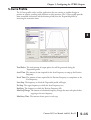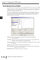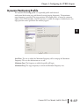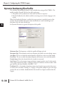
1
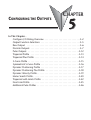
CONFIGURING THE OUTPUTS
CHAPTER
5
In This Chapter...
Configure I/O Dialog Overview . . . . . . . . . . . . . . . . . . . . . . . . . . . .5–2
Output Function Selections . . . . . . . . . . . . . . . . . . . . . . . . . . . . . . .5–5
Raw Output . . . . . . . . . . . . . . . . . . . . . . . . . . . . . . . . . . . . . . . . . .5–6
Discrete Outputs . . . . . . . . . . . . . . . . . . . . . . . . . . . . . . . . . . . . . . .5–7
Pulse Outputs . . . . . . . . . . . . . . . . . . . . . . . . . . . . . . . . . . . . . . . .5–12
Trapezoid Profile . . . . . . . . . . . . . . . . . . . . . . . . . . . . . . . . . . . . . .5–13
Trapezoid Plus Profile . . . . . . . . . . . . . . . . . . . . . . . . . . . . . . . . . . .5–14
S-Curve Profile . . . . . . . . . . . . . . . . . . . . . . . . . . . . . . . . . . . . . . . .5–15
Symmetrical S-Curve Profile . . . . . . . . . . . . . . . . . . . . . . . . . . . . . .5–16
Dynamic Positioning Profile . . . . . . . . . . . . . . . . . . . . . . . . . . . . . .5–17
Dynamic Positioning Plus Profile . . . . . . . . . . . . . . . . . . . . . . . . . .5–18
Dynamic Velocity Profile . . . . . . . . . . . . . . . . . . . . . . . . . . . . . . . . .5–19
Home Search Profile . . . . . . . . . . . . . . . . . . . . . . . . . . . . . . . . . . . .5–20
Trapezoid with Limits Profile . . . . . . . . . . . . . . . . . . . . . . . . . . . . .5–22
Free Form Profile . . . . . . . . . . . . . . . . . . . . . . . . . . . . . . . . . . . . . .5–25
Additional Pulse Profiles . . . . . . . . . . . . . . . . . . . . . . . . . . . . . . . . .5–26
Chapter 5: Configuring the CTRIO Outputs
1
2
3
4
5
6
7
8
9
10
11
12
13
14
A
B
C
D
Configure I/O Dialog Overview
5–2
The Configure I/O dialog is the location where input and output functions are assigned to
the module. The choice of input and output functions determines which options are
available.
The input and output function boxes prompt you with selections for supported functions.
The configuration software disallows any unsupported selections.
For DirectLOGIC users, from the main CTRIO Workbench
window, click on the “Go to PROGRAM Mode” button (if in
RUN Mode). Then, click on the “Config I/O” button to arrive at
a dialog shown below. Notice that the window has a tab for each
input Channel. Channel 1 and Channel 2 offer the same
configuration options. Remember that the H0-CTRIO(2) only has one input channel.
H2, H4, T1H-CTRIO, H2-CTRIO2
Configure I/O Dialog
H0-CTRIO(2)
Configure I/O Dialog
Counter I/O User Manual, 2nd Ed., Rev. D
Chapter 5: Configuring the CTRIO Outputs
For Do-more users, the Workbench options have been built into the Do-more Designer
software. The configuration dialog is found by first opening the System Configuration
window by selecting the “XY Configure” button in the main toolbar.
With the System Configuration page open, select the Module Configuration(s) page from the
lefthand column. On this page, highlight the desired CTRIO module and click Edit Config.
Counter I/O User Manual, 2nd Ed., Rev. D
1
2
3
4
5
6
7
8
9
10
11
12
13
14
A
B
C
D
5–3
Chapter 5: Configuring the CTRIO Outputs
1
2
3
4
5
6
7
8
9
10
11
12
13
14
A
B
C
D
5–4
Now the Edit CTRIO/CTRIO2 Configuration window should be open, click the “Configure
I/O...” button.
You should now have the Configure
I/O window open, similar to the one
shown here, with a tab for each input
Channel.
The input options are listed by
function. Four boxes labeled A, B, C,
and D correspond to the input
terminals on the face of the module
(1A-1D or 2A-2D; A-D for the H0CTRIO(2)).
The Output functions are listed as 0,
1, 2, and 3. These numbers
correspond to the markings beside the
module’s output terminals (Y0-Y3; Y0Y1 for the H0-CTRIO(2)).
Counter I/O User Manual, 2nd Ed., Rev. D
Chapter 5: Configuring the CTRIO Outputs
For DirectLOGIC users, be sure to write the changes to the module from Workbench when
the configuration is complete. For example, you might click on “Discrete Output” in the “0”
box, then OK to return to the main Workbench window. Once you arrive back at the main
window, you must click “Write Module” to save your selection to the module. The module
will need to be in Program Mode to perform the Write Module operation. If you do not
perform the Write Module operation (or a Write File operation) your configuration will be
lost upon quitting Workbench. This applies to all changes to the module configuration.
For Do-more users, the “Write Module” button does not exist because the Module
Configuration dialog stores the CTRIO's configuration as a permanent part of the Do-more
controller's System Configuration.
Output Function Selections
Supported Functions
The module supports four output functions:
• Raw
• Pulse (Step/Direction)
• Pulse (CW/CCW)
• Discrete Ch(1,2)/Fn(1,2)
Each function uses one or two output terminals for making connections to field devices (plus
a common). Combinations of the listed functions are possible. The configuration dialog
disallows any unsupported configurations.
CTRIO Memory Usage: Pulse Profiles and Preset Tables
CTRIO configuration software can create a maximum of 255 predefined Pulse Profiles. The
total number of Pulse Profiles available is 255 minus the number of predefined Preset Tables.
Pulse Profiles and Preset Tables are saved as File 1 through File 255. The module has 256
Total Blocks of memory allocated for Pulse Profiles and Preset Tables usage. The number of
memory blocks used varies between Pulse Profiles and Preset Tables.
Counter I/O User Manual, 2nd Ed., Rev. D
1
2
3
4
5
6
7
8
9
10
11
12
13
14
A
B
C
D
5–5
Chapter 5: Configuring the CTRIO Outputs
1
2
3
4
5
6
7
8
9
10
11
12
13
14
A
B
C
D
Raw Output
5–6
The CTRIO module supports Raw output mode. This mode
allows the CPU/controller program to have direct access to the
module’s output points. Each output can be configured for Raw
output mode and each will have a unique control bit.
NOTE: To insure proper operation, the field device wiring and the
configuration must be compatible. For wiring information see Chapter 2.
1A
2A
1B
2B
1C
2C
1D
2D
1M
2M
NC
C2
Refer to “Output Control Bit Definitions (Raw Mode)” on page
6-5 for Raw output control bit addressing.
C0
Y2
Y0
C3
C1
Y3
Y1
The module’s output terminals are
represented by the 0, 1, 2, and 3 boxes
(0 and 1 for the H0-CTRIO(2)) on the
right side of this dialog.
Counter I/O User Manual, 2nd Ed., Rev. D
Chapter 5: Configuring the CTRIO Outputs
Discrete Outputs
The CTRIO module has four discrete outputs numbered Y0-Y3 (Y0-Y1
for the H0-CTRIO(2)). The outputs respond to presets assigned by the
user in the Configure I/O dialog.
The presets are assigned based on the scaled value of an input, or the
raw value if it has no scaled value. The four outputs can all be assigned
to one function, or they can be grouped within functions and within
channels in any manner selected by the user.
To assign output presets, begin by selecting the ouput on the Configure
I/O dialog. The outputs are identified based on terminal number. In the
example to the right, output terminal “0” is designated for a discrete
output.
Once the output selection is made, a new button
appears on the Configure I/O dialog. The button is
labeled as shown to the right. The leading numeral
represents the number of the output terminal. Clicking on the Preset
button causes the Default Output Settings dialog to pop up. Default
settings are loaded on power-up.
On the Output Settings dialog, select “Use Single Preset.” We will
discuss Preset Tables later in this
chapter. Now, click OK to arrive at
the Edit Preset Entry dialog.
Six output functions are available (as shown in the figure
below). Set the preset value in engineering units if the
signal has been scaled. Set the preset value in raw count if
the signal has not been scaled. We discuss scaling in
chapter 4. Pulse ON and Pulse OFF require a Pulse Time
setting. The Pulse Time is set in msec (1,000 sec = 1 msec)
Output Function Definitions
Set
Writes output ON (maintained)
Reset
Writes output above OFF
Pulse On
Writes output ON for specified time
Pulse Off
Writes output OFF for specified time
Toggle
Changes state of output
Reset Count
Resets the count to Preset Value
Counter I/O User Manual, 2nd Ed., Rev. D
1
2
3
4
5
6
7
8
9
10
11
12
13
14
A
B
C
D
5–7
Chapter 5: Configuring the CTRIO Outputs
1
2
3
4
5
6
7
8
9
10
11
12
13
14
A
B
C
D
5–8
Creating and Using the Programmable Limit Switch (CTRIO2 only)
A Programmable Limit Switch (PLS) is a discrete output table used to turn an output ON or
OFF at multiple points across an input’s range.
The PLS function is only available in the Hx-CTRIO2. A PLS table must be created in the
CTRIO module configuration. Once created, it can be edited using the configuration
application or for Do-more systems, it can be edited using the PLS instructions in ladder. For
greater flexibility when using Do-more systems, create PLS tables in the CTRIO module
configuration then populate their entries (up to 128) from ladder. If using the ladder
instructions, run them after a power cycle to regenerate the tables.
To use a PLS table, an output must be configured as a discrete output paired with a counter
or timer input function. For example, Channel 1 inputs A and B could be configured for
quadrature counting, which would be Channel1Function1. Output 0 could be configured as
Discrete on Ch1/Fn1. When a PLS table is loaded for Output 0, the CTRO2 will monitor
the input value for Ch1/Fn1 (Channel1 quad counter) and Output 0 will be the output
turned ON and OFF by the table.
NOTE: Since a CTRIO Output’s function is fixed in the configuration, an output cannot be changed
programmatically to reference a different input function. This specific change requires a configuration
change and project transfer.
To create a PLS table, from the EditCTRIO/CTRIO2 Configuration window click Discrete
Tables then select Add PLS Table (as seen on following page). Name the table and if the PLS
entries will be populated from ladder in Do-more, leave the table empty and click OK.
Otherwise, use the buttons on the right to build and modify a PLS table. If an input channel
has scaling, it will show in the Scales list, and entries can optionally be entered in scaled units
after selecting the appropriate entry in the Scales list.
Counter I/O User Manual, 2nd Ed., Rev. D
Chapter 5: Configuring the CTRIO Outputs
The table entries are very simple. Select a default value for the discrete output, the output will
be in this state if the input is not within a defined range. Add an entry for each range of input
values where the output should be in the opposite state.
NOTE: Unlike a preset table, events in a PLS table can occur in any order, even simultaneously.
In ladder, use the CTRIO Table Load (CTTBLLD) instruction to load the table for an
output. Loading the table could take multiple scans. When CTTBLLD’s On Success
indication becomes true, set the output’s .EnableOutput structure member to begin using the
table.
For more detailed information, see the Do-more Designer help file topics for CTRIO Module
Configuration, CTTBLADD, CTTBLCLR, CTTBLEDT and CTTBLLD.
Counter I/O User Manual, 2nd Ed., Rev. D
1
2
3
4
5
6
7
8
9
10
11
12
13
14
A
B
C
D
5–9
Chapter 5: Configuring the CTRIO Outputs
1
2
3
4
5
6
7
8
9
10
11
12
13
14
A
B
C
D
5–10
Creating and Using the Output Preset Tables
Preset tables can be used only when the corresponding input is configured for a timer or
quad/counter that is not scaled or if a counter is set to Position scaling.
For DirectLOGIC users, click the
Preset Tables button on the main
Workbench dialog. This will open the
Output Preset Tables dialog. To create a new table, click
Add (or Edit). This will open the Edit Preset Table dialog.
For Do-more users, from the Edit CTRIO/CTRIO2
Configuration page, click the “Discrete Tables...” button.
This will open the Discrete Output Tables dialog. To
create a new table, click Add (or Edit). This will open the
Edit Preset Table dialog.
Build a Preset Table by adding preset entries one at a time.
Click Add Preset (or Edit Preset) to open the Edit Preset
Entry dialog.
NOTE: The preset tables work similiar to an event drum, not a programmable limit switch. For example, in
the Edit Preset Table dialog below, the output is SET at count 100. Once the output is SET, if the count
drops below 100, the output will not go OFF, it will remain SET. Once a step is complete, the focus is on the
next step and that step only.
On the Edit Preset Entry dialog, select one
of the six Output Functions. Set the preset
value in engineering units if the signal has
been scaled. Set the preset value in raw
count if the signal has not been scaled. We
discuss scaling elsewhere in this chapter.
Pulse ON and Pulse OFF require a Pulse
Time setting.
The Pulse Time is set in ms (1,000 ms = 1 sec). For a
description of the Output Functions see page 5-6.
To set a particular table as the default table, use the
Default Output Settings dialog described on page 5-6.
Counter I/O User Manual, 2nd Ed., Rev. D
Chapter 5: Configuring the CTRIO Outputs
Using the Discrete Outputs in Level Mode
If a Counter or Timer function is scaled to produce a rate, alarm level settings can be used to
trigger discrete outputs at values predetermined by the user.
Click the Level button on the Configure I/O dialog. This will
open the Default Output Settings (Level Mode)dialog.
The alarm level is set within the Default Output
Settings (Level Mode) dialog.
Also, a deadband percentage (in tenths of a
percent) can be set to prevent the output from
changing too frequently (chattering) near the Rate
Level threshold.
“ON when greater” condition example:
Consider a Discrete Output set to turn ON when a
level gets to 500 rpm with a 10% deadband. The
output will turn ON when the level gets to 100. If
the level drops, the output will stay on until the
level drops below 450 rpm, where it will turn OFF.
“OFF when less” condition example:
Consider a Discrete Output set to turn “OFF when
less”at 500. When the level gets to 500, the output
turns OFF. If the level rises again, the output will
stay OFF until the level gets to 550, where it will
turn ON.
Counter I/O User Manual, 2nd Ed., Rev. D
1
2
3
4
5
6
7
8
9
10
11
12
13
14
A
B
C
D
5–11
Chapter 5: Configuring the CTRIO Outputs
1
2
3
4
5
6
7
8
9
10
11
12
13
14
A
B
C
D
Pulse Outputs
5–12
The CTRIO module offers up to two axes
of motion control (Y0 and Y1 as an axis
and/or Y2 and Y3 as an axis). The H0CTRIO(2) has one axis of motion control
(Y0 and Y1). The outputs can be
configured for CW/CCW, or step and
direction operation. The outputs respond
to profiles defined by the user and called
by the user control program. The
following pulse profiles are supported:
• Trapezoid
• S-Curve
• Symetrical S-Curve
• Dynamic Positioning
• Dynamic Velocity
• Home Search
• Free Form
• Dynamic Positioning Plus (CTRIO2)
• Trapezoid Plus (CTRIO2)
• Trapezoid w/ Limits (CTRIO2)
There are three additional pulse profiles that are
available to use that are not created using the Pulse
Ouput Profiles Tables. These profiles: Velocity Mode,
Run to Limit Mode and Run to Position Mode are
discussed at the end of this chapter.
Creating Pulse Output Profile Tables
For DirectLOGIC users, click the Pulse Profiles button
on the main Workbench dialog.
For Do-more users, click the
“Pulse Profiles...” button from
the Edit CTRIO/CTRIO2
Configuration window. This will
open the Pulse Profiles Tables dialog. To
create a new profile, click Add (or Edit).
This will open the Edit Pulse Profile
dialog.
On the Edit Pulse Profile dialog, select one
of the ten Pulse Profile Types.This dialog is
used to name and define the pulse profile
parameters. The various parameter fields
contain typical default values. The
configuration software will disallow any
invalid parameter entries.
Counter I/O User Manual, 2nd Ed., Rev. D
Chapter 5: Configuring the CTRIO Outputs
Trapezoid Profile
The Trapezoid profile changes the velocity in a linear fashion from the specified Start
Frequency until the specified target Position Frequency is reached. During decelerating, the
velocity changes in a linear fashion from the specified Position Frequency until the specified
End Frequency and Total Pulses is reached.
Acceleration Time
Position Frequency
End Frequency
Start Frequency
Deceleration Time
Total Pulses: The total amount of output pulses that will be generated during the
Trapezoidal profile.
Accel Time: The amount of time required for the Start Frequency to ramp up the Position
Frequency.
Decel Time: The amount of time required for the Position Frequency to ramp down to the
End Frequency.
Start Freq: The frequency at which the Trapezoidal profile will begin.
Pos Freq: The target frequency to which the Start Frequency rises.
End Freq: The frequency to which the Position Frequency falls.
Counter I/O User Manual, 2nd Ed., Rev. D
1
2
3
4
5
6
7
8
9
10
11
12
13
14
A
B
C
D
5–13
Chapter 5: Configuring the CTRIO Outputs
Trapezoid Plus Profile
1
2
3
4
5
6
7
8
9
10
11
12
13
14
A
B
C
D
5–14
The Trapezoid Plus profile is only available when using an Hx-CTRIO2. See Trapezoid
description for a general description of this profile. The profile resembles Trapezoid Profile,
but has four additional features:
1. The target position is a variable (parameter 3) set by the base controller, instead of a
constant specified in the profile.
2. The profile can be asymmetrical. (Accel and Decel rates are separate)
3. Encoder Feedback can be added, useful for correcting excessive lash or slippage in the
system.
4. Allows output rates up to 250kHz.
When Use Encoder for Position is enabled, the target position is specified in units of the
encoder. Encoder feedback determines when deceleration of a move should begin and
determines when the move should stop. If Scale Factor is set incorrectly, the output could
overshoot the target position, or start decelerating too soon.
Minimum Freq: The frequency at which the profile will begin and end.
Maximum Freq: The maximum steady state frequency the profile can attain during a move.
Accel Rate: The rate at which the output frequency will increase at the start of the profile.
Decel Rate: The rate at which the output frequency will decrease at the end of the profile.
Encoder Input: Select the channel where the encoder is connected. The inputs for the
encoder (A&B) must be configured for Quad Counter.
Scale Factor: This is the output to input resolution (stepper/encoder) ratio. In other words,
if the stepper motor being used is a 1000 ppr (pulses per revolution) and the encoder is 800
ppr, then the scale factor would be 1000/800 = 1.25.
Deadband: This is the number of position counts away from the target position that causes
no action. This can reduce "hunting" or "ringing" as the profile attempts to get to the target
position. Be sure to include a deadband when the encoder has a higher resolution than the
stepper.
Counter I/O User Manual, 2nd Ed., Rev. D
Chapter 5: Configuring the CTRIO Outputs
S-Curve Profile
The S-Curve profile can be used for applications that are sensitive to sudden changes in
position or velocity, resulting with vibrations or jerky reactions. The S-Curve profile provides
more controlled acceleration and deceleration periods than the Trapezoidal profile by
increasing the transistion times.
Total Pulses: The total amount of output pulses that will be generated during the
Trapezoidal profile.
Accel Time: The amount of time required for the Start Frequency to ramp up the Position
Frequency.
Decel Time: The amount of time required for the Position Frequency to ramp down to the
End Frequency.
Start Freq: The frequency at which the Trapezoidal profile will begin.
Pos Freq: The target frequency to which the Start Frequency rises.
End Freq: The frequency to which the Position Frequency falls.
Min Freq Change: The amount of calculated frequency change that must take place before
stepping to the next frequency.
Min Entry Time: The amount of time spent in each step.
Counter I/O User Manual, 2nd Ed., Rev. D
1
2
3
4
5
6
7
8
9
10
11
12
13
14
A
B
C
D
5–15
Chapter 5: Configuring the CTRIO Outputs
1
2
3
4
5
6
7
8
9
10
11
12
13
14
A
B
C
D
Symmetrical S-Curve Profile
5–16
The Symmetrical S-Curve profile can also be used for applications that are sensitive to sudden
changes in position or velocity, resulting with vibrations or jerky reactions. The Symmetrical
S-Curve provides more controlled acceleration and deceleration periods than a Trapezoidal
profile by increasing the transistion times.
The S-Curve and Symmetrical S-Curve profiles differ in that the Symmetrical S-Curve has
symmetrical acceleration and deceleration profiles. The Decel Time and End Frequency are
determined by the Accel Time and Start Frequency. The Symmetrical S-Curve uses less
memory than the S-Curve profile.
Total Pulses: The total amount of output pulses that will be generated during the
Trapezoidal profile.
Accel Time: The amount of time required for the Start Frequency to ramp up the Position
Frequency. This also represents the deceleration time.
Start Freq: The frequency at which the Trapezoidal profile will begin. This also represents the
end frequency.
Pos Freq: The target frequency to which the Start Frequency rises.
Min Freq Change: The amount of calculated frequency change that must take place before
stepping to the next frequency
Min Entry Time: The amount of time spent in each step.
Counter I/O User Manual, 2nd Ed., Rev. D
Chapter 5: Configuring the CTRIO Outputs
Dynamic Positioning Profile
The Dynamic Positioning profile is a trapezoidal profile with identical
acceleration/deceleration rates and identical starting/stoping frequencies. The maximum
target frequency is specified. The target position (# of output pulses) is located in a memory
register in the CPU/controller. Once the position is reached, the output is disabled and a new
target position can be specified in the memory register.
Accel Rate: The rate at which the Minimum Frequency will to ramp up the Maximum
Frequency. This sets the deceleration rate as well.
Minimum Freq: The frequency at which the profile will begin.
Maximum Freq: The target frequency to which the Minimum Frequency rises.
Counter I/O User Manual, 2nd Ed., Rev. D
1
2
3
4
5
6
7
8
9
10
11
12
13
14
A
B
C
D
5–17
Chapter 5: Configuring the CTRIO Outputs
1
2
3
4
5
6
7
8
9
10
11
12
13
14
A
B
C
D
Dynamic Positioning Plus Profile
5–18
The Dynamic Positioning Plus profile is only available when using an Hx-CTRIO2. The
profile resembles Dynamic Position, but adds two features:
1. The profile can be asymmetrical. (Accel and Decel Rates are separate)
2. Encoder Feedback can be added, useful for correcting excessive lash or slippage in the
system.
When Use Encoder for Position is enabled, the target position is specified in units of the
encoder. Encoder feedback determines when deceleration of a move should begin and
determines when the move should stop.
See Dynamic Position for a general description of this profile.
Minimum Freq: The frequency at which the profile will begin and end.
Maximum Freq: The maximum steady state frequency the profile can attain during a move.
Accel Rate: The rate at which the output frequency will increase at the start of the profile.
Decel Rate: The rate at which the output frequency will decrease at the end of the profile.
Encoder Input: Select the channel where the encoder is connected.
Scale Factor: This is the output to input resolution (stepper/encoder) ratio. In other words,
if the stepper motor being used is a 1000 ppr (pulses per revolution) and the encoder is 800
ppr, then the scale factor would be 1000/800 = 1.25.
Deadband: This is the number of position counts away from the target position that causes
no action. This can reduce "hunting" or "ringing" as the profile attempts to get to the target
position. Be sure to include a deadband when the encoder has a higher resolution than the
stepper.
Counter I/O User Manual, 2nd Ed., Rev. D
Chapter 5: Configuring the CTRIO Outputs
Dynamic Velocity Profile
The Dynamic Velocity profile is a trapezoidal profile with the direction acceleration and
deceleration rates specified. The target velocity is located in a memory register in the
CPU/controller. Once the CPU/controller initiates the profile, output pulses will be
generated at the target velocity until the CPU/controller disables the output pulses.
Clockwise Accel Rate: The clockwise rate at which the output will ramp up from 0pss to the
target velocity that is specified in the CPU/controller memory register.
Clockwise Decel Rate: The clockwise rate at which the output will ramp down from the
target velocity that is specified in the CPU/controller memory register to 0pss.
Counter-Clockwise Accel Rate: The counter-clockwise rate at which the output will ramp
up from 0pss to the target velocity that is specified in the CPU/controller memory register.
Counter-Clockwise Decel Rate: The counter-clockwise rate at which the output will ramp
down from the target velocity that is specified in the CPU/controller memory register to
0pss.
Counter I/O User Manual, 2nd Ed., Rev. D
1
2
3
4
5
6
7
8
9
10
11
12
13
14
A
B
C
D
5–19
Chapter 5: Configuring the CTRIO Outputs
Home Search Profile
1
2
3
4
5
6
7
8
9
10
11
12
13
14
A
B
C
D
5–20
The Home Search profile is used to “find the home position”, which is usually a reference point
to which the object being moved can return upon command at any time during or after the
execution of a positioning profile.
There are several Home Search routines to choose from, all with the option to designate
whether you want Limit 1 and/or Limit 2 (a CTRIO discrete input) to register on the rising
edge, falling edge, high level or low level signal. Limit 1 and Limit 2 can be the opposite
edges of the same physical CTRIO input.
NOTE: The Home Search profile requires that CTRIO inputs C and/or D are configured for Limit Out 0 or
Limit 2. This is done using the Configure I/O dialog.
Frequency 1: The frequency at which the Home Search will begin.
Limit 1: Home Search Frequency 1 will run to CTRIO input Limit 1 and stop unless
Frequency 2 is enabled.
Frequency 2: (if enabled) Once Limit 1 is reached, the pulse output will continue at
Frequency 2 until CTRIO Limit 2 is reached or pulse Count is reached at Frequency 2.
Limit 2: (if enabled) Home Search Frequency 2 will run to CTRIO input Limit 2 and stop.
Count: (if enabled) The number of output pulse counts generated at Frequency 2 before
terminating.
Counter I/O User Manual, 2nd Ed., Rev. D
Chapter 5: Configuring the CTRIO Outputs
Home Search Routines
1. Run to Limit 1 at Frequency 1.
Frequency 1
Limit 1 (Home)
2. Run to Limit 1 at Frequency 1, then continue to Limit 2 at Frequency 2.
Frequency 1
Frequency 2
Limit 1
Limit 2 (Home)
3. Run to Limit 1 at Frequency 1, then reverse to Limit 2 at Frequency 2.
Frequency 1
Frequency 2
Limit 1
Limit 2 (Home)
4. Run to Limit 1 at Frequency 1, then continue to Count at Frequency 2.
Frequency 2
Count (Home)
Frequency 1
Limit 1
5. Run to Limit 1 at Frequency 1, then reverse to Count at Frequency 2.
Frequency 1
Frequency 2
Limit 1
1
2
3
4
5
6
7
8
9
10
11
12
13
14
A
B
C
D
Count (Home)
Counter I/O User Manual, 2nd Ed., Rev. D
5–21
Chapter 5: Configuring the CTRIO Outputs
1
2
3
4
5
6
7
8
9
10
11
12
13
14
A
B
C
D
Trapezoid with Limits Profile
5–22
The Trapezoid with Limits profile is only available when using an Hx-CTRIO2. The profile
is a homing routine similar to Home Search but has five additional features:
1. The profile is trapezoidal (has linear accel and decel rates), allowing for faster homing
routines without stalling the stepper.
2. The profile can be asymmetrical. (Accel and Decel rates are separate)
3. Encoder Feedback can be added, useful for correcting excessive lash or slippage in the
system.
4. Allows output rates up to 250kHz.
5. When Stop Trigger is position, it is a variable (parameter 3), set by the base controller.
NOTE: When using an input channel as the Stop Trigger with this profile, the Stop Trigger must be beyond
the first limit in the same direction. The output cannot change direction to reach the second limit. Use
Home Search if the output must Reverse to Limit 2.
The Trapezoid with Limits profile offers several routines using a Decel Trigger and Stop
Trigger. Specify the Decel Trigger as the rising or falling edge of a CTRIO2 input. The Stop
Trigger can be a position relative to the Decel Trigger, the opposite edge of the Decel Trigger
or the rising or falling edge of another CTRIO2 input.
NOTE: The Trapezoid with Limits profile requires that CRTIO2 inputs C and/or D are configured for Limit
Out X, where X is the output channel being used.
Decel Trigger: The CTRIO2 input to use as the Decel Trigger. Hitting this limit during the
move will either reset counts to 0 (if Stop Trigger is position) or initiate deceleration to the
Creep Frequency (if Stop Trigger is a CTRIO2 input).
Event: The edge of the limit switch to use as the Decel Trigger.
Counter I/O User Manual, 2nd Ed., Rev. D
Chapter 5: Configuring the CTRIO Outputs
Stop Trigger: The CTRIO2 input or position that stops the output. If Position is selected,
Parameter 3 defines the target position. This is relative to 0, which is clocked in when the
Decel Trigger’s Event condition is met. Position can be positive or negative.
Event: The edge of the limit switch to use as the Stop Trigger.
Minimum Freq: The frequency at which the profile will begin and end.
Maximum Freq: The maximum steady state frequency the profile can attain during a move.
Accel Rate: The rate at which the output frequency will increase at the start of the profile.
Decel Rate: The rate at which the output frequency will decrease when Decel Trigger is
reached.
Creep Freq: The (slower) rate to use between the Decel Trigger and the Stop Trigger.
Encoder Input: Select the channel where the encoder is connected.
Scale Factor: This is the output to input resolution (stepper/encoder) ratio. In other words, if
the stepper motor being used is a 1000 ppr (pulses per revolution) and the encoder is 800
ppr, then the scale factor would be 1000/800 = 1.25.
Deadband: This is the number of position counts away from the target position that causes
no action. This can reduce "hunting" or "ringing" as the profile attempts to get to the target
position. Be sure to include a deadband when the encoder has a higher resolution than the
stepper.
Example: Trapezoid with Limits using a limit switch for the Stop Trigger.
Velocity
Position
4
1
5
3
2
1. Move starts at the Minimum Freq and accelerates at Accel Rate.
2. Acceleration ends at Maximum Freq and move continues at Maximum Freq.
3. When the Decel Trigger is reached, the position register is zeroed out and the output begins to
slow down at Decel Rate.
4. Deceleration ends at Creep Freq and the move continues towards the Stop Trigger, a limit switch.
5. When the Stop Trigger is reached, the output stops.
Counter I/O User Manual, 2nd Ed., Rev. D
1
2
3
4
5
6
7
8
9
10
11
12
13
14
A
B
C
D
5–23
Chapter 5: Configuring the CTRIO Outputs
Example: Trapezoid with Limits using a position for the Stop Trigger. The Stop Trigger
position does not require change of direction.
-2000
0
Velocity
Position
4
1
5
3
2
1. Move starts at the Minimum Freq and accelerates at Accel Rate.
2. Acceleration ends at Maximum Freq and move continues at that rate.
3. When the Decel Trigger is reached, the position register is zeroed out and the output begins to
slow down at Decel Rate.
4. Deceleration ends at Creep Freq and the move continues towards the Stop Trigger, a position
relative to the Decel Trigger. The Stop Trigger is the position -2000 in this example.
5. When the Stop Trigger is reached, the output stops.
Example: Trapezoid with Limits using a position for the Stop Trigger. The Stop Trigger
position requires change of direction.
400
0
Position
5
4
Velocity
1
2
3
4
5
6
7
8
9
10
11
12
13
14
A
B
C
D
1
3
2
1. Move starts at the Minimum Freq and accelerates at Accel Rate.
2. Acceleration ends at Maximum Freq and move continues at that rate.
3. When the Decel Trigger is reached, the position register is zeroed out and the output begins to
slow down at Decel Rate.
4. Deceleration ends at Minimum Freq and the move changes direction to move back towards the
Stop Trigger, a position relative to the Decel Trigger.
5. When the Stop Trigger is reached (position 400 in this example), the output stops.
5–24
Counter I/O User Manual, 2nd Ed., Rev. D
Chapter 5: Configuring the CTRIO Outputs
Free Form Profile
The Free Form profile allows for stepping between output frequencies with no acceleration or
deceleration ramps. Profiles, up to 256 steps, can be imported from a CSV file.
Total Pulses: Provided by the utility, the total number of output pulses that will be generated
during the profile.
Total Time: The total time required for the profile to run to completion.
Import: Opens a dialog that allows importing a CSV file. Importing the CSV replaces the
existing entries. A CSV file used to create the profile seen above would look like:
200,20
100,30
Add or Edit Step: Will invoke the Edit Pulse Entry dialog seen below. This window will allow
you to modify or create pulse entries.
• Pulse Count: The number of pulses to generate for this step.
• Frequency: The frequency of pulses during this step.
Counter I/O User Manual, 2nd Ed., Rev. D
1
2
3
4
5
6
7
8
9
10
11
12
13
14
A
B
C
D
5–25
Chapter 5: Configuring the CTRIO Outputs
1
2
3
4
5
6
7
8
9
10
11
12
13
14
A
B
C
D
Additional Pulse Profiles
Three additional pulse profiles are available to use that are not
defined or created using the Pulse Profiles Table dialog, however
the output(s) must be configured for Pulse (Step/Direction) or
Pulse (CW/CCW) using the Configure I/O dialog. The profile
parameters are stored in the CPU/controller memory registers.
The profiles are briefly described below and will be discussed in
detail in Chapter 6. With all three profiles, the output is a step
response output to the specified target frequency, thus no
acceleration/deceleration parameters are configured.
Velocity Mode: User specifies the target frequency, pulse train
duty cycle and the step count. Once initiated, the output will
begin pulsing at the target frequency and continue until the step count is reached. With a step
count of 0xFFFFFFFF, the pulse output will continue indefinetly until the control program
disables the output.
Run to Limit Mode: User specifies target frequency and pulse train duty cycle. A CTRIO
module input (C or D) must be configured as a Limit input. When the Limit is reached the
pulse output is disabled.
Run to Position Mode: User specifies target frequency, pulse train duty cycle and target
position. The current position is obtained from the specified Input Function (i.e. Quadrature
counter). When the current position reaches the specified target position, the pulse output is
disabled. The comparing of the current and target position can be based on “greater than or
equal to” or “less than” values.
Hx-CTRIO2 with Do-more
In addition to the profiles in this manual, when an Hx-CTRIO2 is used with Do-more, Axis
Mode instructions are also available. With Axis Mode, it is not necessary to store profiles in
the CTRIO2. Instead, profile parameters are specified in a CTAXCFG (CTRIO2 Axis
Configuration) instruction. Then other Axis Mode instructions call for motion from the
module, which carries out their requests while adhering to the CTAXCFG parameters. Axis
Mode instructions also have stage control options for the complete or error events. Stage
programming tends to be well suited to motion applications, which are often sequential
processes.
Do-more CTRIO2 Axis Mode instructions:
CTRIO2 Axis Configuration (CTAXCFG)
CTRIO2 Axis Run Dynamic Position (CTAXDYNP)
CTRIO2 Axis Run Dynamic Velocity (CTAXDYNV)
CTRIO2 Axis Run Trapezoid (CTAXTRAP)
CTRIO2 Axis Run Trapezoid with Limits (CTAXLIMT)
CTRIO2 Axis Jog (CTAXJOG)
See Do-more Designer help file for more information.
5–26
Counter I/O User Manual, 2nd Ed., Rev. D