1
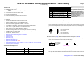
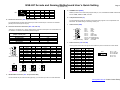
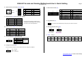
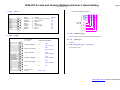
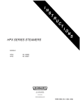
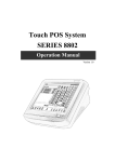
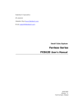
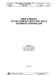
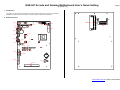
GSE-627 Arcade and Gaming Motherboard User’s Quick Setting
Page 1/5
( Version 1.0 )
1. Introduction
The PCB is a Low power PII or PIII Grade, all in one, half-size CPU card. This user’s quick setting
provides the jumper and switch settings, connector location, and their pin assignment.
2. Board Placement
CN11
DIMM1
CN8
J7
CN5
JP3
CN7
CN1
DB2
J5
J4
CN6
J10
BZ1
CN9
JP2
BT2
LED1
CN2
J9
DB1
J1
CN4
J3
JP1
CN3
J8
CN10
SW3
SW4
SW2
SW1
CON1
CON5
BT1
CON2
SW5
BUS2
www.gauss.com.tw / ©2007 Gauss Enterprise
GSE-627 Arcade and Gaming Motherboard User’s Quick Setting
Page 2/5
( Version 1.0 )
3. Packing List
1. GSE-627 Arcade and Gaming all-in-one CPU board.
2. 256 M DDR400 RAM module.
3. CPU: Genuine Intel® Processor 1.3GHZ( 100x13.0) , CPU Name: Intel® Celeron® M Processor
1300MHZ.
4. Y-type keyboard and mouse port adapter cable.
5. USB and Audio adapter board with cable.
6. CPU heat sink with cooling fan.
7. Hard copies of this quick setup manual.
8. Serial port and Parallel port interface cable with bracket.
CN6
CN7
CN8
CN9
CN10
CN11
DB1
DB2
DIMM1
LED1
Parallel Port Connector (26-pin IDC)
LVDS Connector (30-pin DF13)
LCD Power Connector (5-pin JST)
Mini ATX Connector (20-pin)
Audio Connector (J2x5)
USB #1 & #2 Connector (USB 2.0)
COM1 Connector (9-pin D-sub)
CRT Connector (15-pin D-sub)
SoDIMM Socket (200-pin)
On-Board Power/WD LED (Green)
J6
J7
J8
J9
J10
JP1
JP2
JP3
BUS2
BZ1
n. a.
TTL I/O Connector (5-pin JST)
CPU Cooling Fan Connector (3-pin)
AC97 Signals Connector (12-pin)
USB #3 & #4 Connector (J2x5)
PS2/ATX Power Select Jumper (J1x2))
COM2 Mode Select Jumper (J2x3)
WOL Select Jumper (J1x3)
PCI Connector (120-pin)
On-Board Buzzer
4. Features
A. Motherboard:
* On-board low power Intel Pentium-M (Optional) or socket for Celeron-M and Pentium-M CPUs
* Compact size slot card with PICMG PCI expansion bus.
* Intel 855GME+ICH4 chipset and 512KB or above L2 cache inside the CPUs.
* Supports 1 SoDIMM socket for up to 1GB DDR-333 RAM.
* 10/100/1000 base-TX (Giga) Ethernet with RJ-45 connector.
* Onboard VGA port (855GME embedded) supports CRT and LVDS interface.
* 1 PCI IDE and 1 CompactFlash socket for 3.3V CompactFlash and MicroDrive.
* 4 USB (V2.0), 1 parallel, 1 RS-232 and 1 RS-232/422/485 ports.
* PS/2 compatible keyboard and mouse interface.
* E2KEY functions for safe CMOS data keeping. (Optional)
* 4-line TTL I/O, On-board buzzer, and LED indicator.
* Hardware monitoring functions and 1 CPU cooling fan connector for monitoring.
* Provides AC97 Audio function and software programmable watchdog timer.
* Flash BIOS with easy upgrade utility.
* Compact size, 185 mm x 122 mm.
B. I/O:
* Both Arcade Game and Gambling Game are available.
* Input Port: 8pin
* Output Port: 5pin
* Wiring Matrix: 5x6
* Dip Switch: 4(set)x8pin
* RAM: 256K extendable to 512k
* ROM: 512K extendable to 8M+32M
C. Programming:
* This motherboard provides on-line compiler for VC, Turbo C, Delphi, etc. which are coded by
assembly language.
* GAUSS will provide Gcc example.
Function
40-pin IDE Connector (40-pin IDC)
LAN Connector (RJ45 w/LEDs)
KB/Mouse Connector (6-pin mini-Din)
KB/Mouse Connector (6-pin JST)
COM2 Connector (10-pin IDC)
A. Keyboard and Mouse Connectors (CN3 and CN4)
CN3 is a standard PS/2 type keyboard connector and any PS/2 type keyboard can plug into CN3
directly without extra adapter cable. Use the included keyboard+mouse adapter cable (Optional),
you can connect keyboard and mouse simultaneously. CN4 is another way to attach keyboard and
mouse with optional adapter cable.
CN4
CN3
Name
J1
J2
J3
J4
J5
Function
Clear CMOS data Header (J1x2))
n. a.
ATX Signals Connector (4-pin JST)
Integrated Signals Connector (J2x8)
CompactFlash Socket (50-pin)
6 Pin 1:
Pin 2:
Pin 3:
Pin 4:
Pin 5:
1 Pin 6:
Mouse Data
Keyboard Data
Ground
VCC
Mouse Clock
Keyboard Clock
B. Power Connector (CN9), ATX Power Signal Connector and Jumper (J3 and JP1)
CN9 is a standard 20-pin ATX power connector, Please connect pins 15 and 16 of J4 to a push
bottom switch for ATX power On/Off controls (Soft start switch).
JP1: Power Supply Select Jumper
J3
1
5. Connectors and Jumpers List
Name
CN1
CN2
CN3
CN4
CN5
6. Connectors and Their Relative Jumpers
4
Pin 1:
Pin 2:
Pin 3:
Pin 4:
Ground
PSON#
N. C.
VCCSB
2
1
ATX Power Supply
JP1
2
1
PS2 Power Supply
JP1
Factory Preset
C. LAN Connector and LED Indicators (CN2)
CN2 is a RJ45 connector with 2 LEDs. The up side LED (orange) indicates data access and the
down side LED (green) indicates on-line status. (When light is on indicates on-line and off indicates
off-line)
www.gauss.com.tw / ©2007 Gauss Enterprise
GSE-627 Arcade and Gaming Motherboard User’s Quick Setting
Page 3/5
( Version 1.0 )
CN2 10/100
1
TPTX+
2
TPTX3
TPRX+
4
FBG1
CN2
8
1
(Front View)
Giga
MDI0+
MDI0MDI1+
MDI2+
CN2
5
6
7
8
10/100
FBG1
TPRXFBG2
FBG2
G. SoDIMM Socket (DIMM1)
Giga
MDI2MDI1MDI3+
MDI3-
DIMM1 (Located on the solder side) supports 200-pin, 2.5V, and DDR-333 DRAM modules with
size of 128MB, 256MB, 512MB, and 1GB.
H. CompactFlash Socket (J5)
D. Parallel Port Connector (CN6: 26-pin 2.0mm IDC)
The included printer interface cable (optional) is used to transfer 26-pin connector into standard
parallel port connector (D-sub 25-pin).
The CompactFlash socket J5 (Located on the solder side) supports 3.3V CompactFlash and
MicroDrive. Its default setting is secondary master port.
I.
CRT Connector (DB2)
E. Serial Port Connectors & Selector (DB1, CN5, and JP2)
There are 2 connectors and 1 jumper that served for onboard 2 serial ports. The combination and
pin definition are listed on the following tables and figure:
Functional connector, header, and
jumper of serial ports
RS-232 Signals
RS-422 Signals
RS-485 Signals
Infra Red Signals
Mode Select
1
6
9
5
DB1 (Front View)
5
Serial Port 2
DB1
-
CN5
CN5
CN5
J4 (Please refer to 6.P section)
JP2
DB1
Signals
CN5
1
-DCD1
1
6
-DSR1
2
2
RXD1
3
7
-RTS1
4
3
TXD1
5
8
-CTS1
6
4
-DTR1
7
9
-RI1
8
5
Ground1
9
Metal Case Ground 10
JP2
1
Serial Port 1
JP2
D-sub 9
1
6
2
7
3
8
4
9
5
Metal
JP2
RS-232
-DCD2
-DSR2
RXD2
-RTS2
TXD2
-CTS2
-DTR2
-RI2
Ground2
Case Ground
2
2
1
2
1
2
6
5
6
5
6
5
6
RS-485
(Half Duplex)
RXTXRX+
TX+
RS-422
(Full Duplex)
10
5
1
11
6
DB2 (Front View)
J.
RS-485
485485+
-
JP2
1
RS-232
Factory Preset
RS-422
15
Reserved
Pin 1:
Pin 2:
Pin 3:
Pin 13:
Pin 14:
Pin 12:
Pin 15:
Pin 5 & 10:
Pin 6,7,8:
Others:
Red
Green
Blue
Hsync
Vsync
DDC Data
DDC Clock
Digital Ground
Analog Ground
Not Used
LCD Connectors (CN7 and CN8)
CN7 supports 36-bit LVDS LCD signals, and CN8 is the power connector for inverter board.
CN7
1
3
5
7
9
11
13
15
17
19
21
23
25
27
29
Signal
Ground
Y0Y1+
Ground
Y2YCK+
Ground
Z0Z1+
Ground
Z2ZCK+
Ground
+3.3V
+5V
CN7
2
4
6
8
10
12
14
16
18
20
22
24
26
28
30
Signal
Y0+
Ground
Y1Y2+
Ground
YCKZ0+
Ground
Z1Z2+
Ground
ZCKGround
+3.3V
+5V
CN8
1
5
Pin 1:
Pin 2:
Pin 3:
Pin 4:
Pin 5:
+12V
Ground
ENVDD
N.C.
+5V
F. IDE Hard Disk Connector (CN1 - 40-pin 2.54mm IDC)
Use the included 40-pin hard disk cable (optional), you can attach up to two 3.5” hard disk drives.
www.gauss.com.tw / ©2007 Gauss Enterprise
GSE-627 Arcade and Gaming Motherboard User’s Quick Setting
Page 4/5
( Version 1.0 )
K. USB Connectors and Jumpers (CN11 and J10)
P. Multi-Function Header (J4)
1
J10
1
3
5
7
9
2
USB #1
1
J10
4
USB #2
9
CN11
10
Signal
USB3V+
USBD3USBD3+
Ground
Case Ground
J10
2
4
6
8
10
Signal
USB4V+
USBD4USBD4+
Ground
Case Ground
J4
2
J4
1
3
5
7
9
11
13
15
16
15
1
L. AC97 Connector (J9: 12-pin 2.0mm IDC, optional)
J9
1
3
5
7
9
11
Signal
AC97_CLK
+5V
Ground
N. C.
AC97_SDO
AC97_SDI0
J9
2
4
6
8
10
12
Signal
+12V
AC97_SYNC
Ground
AC97_RST#
AC97_SDI2
AC97_SDI1
Signal
Power LED+
HDD LED+
LAN LED+
Temperature Sensor+
IRTX
Ground
Reset+
Soft Start SW+
J4
2
4
6
8
10
12
14
16
Signal
Power LEDHDD LEDLAN LEDTemperature SensorIRRX
Ground
ResetSoft Start SW-
Q. Clear CMOS Data (J1)
J9 provides AC97 signals for Audio function.
Use FB4641x (Audio adapter board, Optional)
and cable for your Audio applications.
M. Audio Connector (CN10: 10-pin 2.0mm IDC)
CN10
Signal
CN10
Signal
1
3
5
7
9
Line Out – L
Line Out -R
Ground
N. C.
N. C.
2
4
6
8
10
Line In – L
Line In – R
N. C.
MIC In
Ground
J1
J1 is used to clear CMOS data by closing its 2-pin for about 3 seconds.
1 2
R. Wake On LAN (WOL) Select (JP3)
JP3
JP3
1 2 3
1 2 3
WOL Enabled
WOL Disabled
Factory Preset
S. CON5
[ I/O(A) ]
N. TTL I/O Connector (J7: 5-pin 2.0mm JST)
J7
1
5
J7
1
2
3
4
5
TTL Lines
Bit Location
Output Line 0 Please refer to
Output Line 1 User’s Manual
Input Line 0 for details.
Input Line 1
Ground
-
Pin1
Pin2
Pin3
Pin4
Pin5
Pin6
Record
Key in
Key out
Coin
Alarm
GND
Pin7
Pin8
Pin9
Coin Key out Key in
Counter Counter Counter
Pin10
+12V
O. Cooling Fan Connector(J8)
J8 is 3-pin Molex connector which is used to drive CPU cooling fan for FB6613.
J8
1 2
Pin1: Ground
Pin2: +12V
Pin3: Fan Speed
3
www.gauss.com.tw / ©2007 Gauss Enterprise
GSE-627 Arcade and Gaming Motherboard User’s Quick Setting
Page 5/5
( Version 1.0 )
T. CON1
[ Input ]
*External Wiring(Matrix) Diagram:
9-Pin Male
GND
PROTECT
CLOSE
RECORD
TEST
CLEAR
HP.SW
KEYOUT
KEYIN
5
9
4
8
3
7
2
6
1
Ground
Alarm (for key in & key out)
Shut off screen
Record
Test
Clear record
Coin out switch
Key out
Key in
POWER
in 0
in 1
in 2
in 3
in 4
in 5
in 6
in 7
V.
U. CON2
[ I/O(B) ]
25-Pin Female
SW5
[ Hardware Reset ]
Switch it when power is OFF to clear Arcade Game record.
1,14,2,15,3,16,
4,17,5,18,6
*External Wiring(Matrix)
W. BT1
[ Battery 3V ]
CR2032
KEYIN COUNTER
19
Out 0
(open collector)
KEYOUT COUNTER
7
Out 1
(open collector)
COIN COUNTER
2
Out 2
(open collector)
PAYOUT COUNTER
8
Out 3
(open collector)
SSR/ IN-USE LAMP
2
Out 4
(open collector)
COIN
9
in 8
22,10,23,11,24,
12,25,13
X.
SW1、SW2、SW3、SW4
[ Dip Switch ]
On line Game IP set
Power Output
www.gauss.com.tw / ©2007 Gauss Enterprise