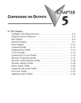
1
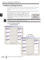
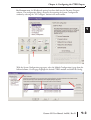
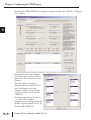
CONFIGURING THE INPUTS
CHAPTER
4
In This Chapter...
Configure I/O Dialog Overview . . . . . . . . . . . . . . . . . . . . . . . . . . . .4–2
Input Function Selections . . . . . . . . . . . . . . . . . . . . . . . . . . . . . . . .4–5
Counter . . . . . . . . . . . . . . . . . . . . . . . . . . . . . . . . . . . . . . . . . . . . .4–6
Quadrature Counter . . . . . . . . . . . . . . . . . . . . . . . . . . . . . . . . . . . .4–7
Pulse Catch . . . . . . . . . . . . . . . . . . . . . . . . . . . . . . . . . . . . . . . . . . .4–8
Edge Timer . . . . . . . . . . . . . . . . . . . . . . . . . . . . . . . . . . . . . . . . . . .4–9
Dual Edge Timer . . . . . . . . . . . . . . . . . . . . . . . . . . . . . . . . . . . . . .4–10
Reset 1 and Reset 2 (Hard Resets for Counters Only) . . . . . . . . . . .4–11
Soft Resets . . . . . . . . . . . . . . . . . . . . . . . . . . . . . . . . . . . . . . . . . .4–11
Capture 1 . . . . . . . . . . . . . . . . . . . . . . . . . . . . . . . . . . . . . . . . . . .4–12
Inhibit 1 . . . . . . . . . . . . . . . . . . . . . . . . . . . . . . . . . . . . . . . . . . . .4–12
Introduction to the Scaling Wizard . . . . . . . . . . . . . . . . . . . . . . . .4–13
Chapter 4: Configuring the CTRIO Inputs
1
2
3
4
5
6
7
8
9
10
11
12
13
14
A
B
C
D
Configure I/O Dialog Overview
4–2
The Configure I/O dialog is the location where input and output functions are assigned to
the module. The choice of input and output functions determines which options are
available.
The input and output function boxes prompt you with selections for supported functions.
The configuration software disallows any unsupported selections.
For DirectLOGIC users, from the main CTRIO Workbench
window, click on the “Go to PROGRAM Mode” button (if in
RUN Mode). Then, click on the “Config I/O” button to arrive at
a dialog shown below. Notice that the window has a tab for each
input Channel.
NOTE: You don’t have to be in PROGRAM mode to enter the Configure I/O dialog, however you must be in
PROGRAM mode to save the configuration to the CTRIO module.
H2, H4, T1H-CTRIO, H2-CTRIO2
Configure I/O Dialog
H0-CTRIO(2)
Configure I/O Dialog
Counter I/O User Manual, 2nd Ed., Rev. D
Chapter 4: Configuring the CTRIO Inputs
For Do-more users, the Workbench options have been built into the Do-more Designer
software. The configuration dialog is found by first opening the System Configuration
window by selecting the “XY Configure” button in the main toolbar.
With the System Configuration page open, select the Module Configuration(s) page from the
lefthand column. On this page, highlight the desired CTRIO module and click Edit Config.
Counter I/O User Manual, 2nd Ed., Rev. D
1
2
3
4
5
6
7
8
9
10
11
12
13
14
A
B
C
D
4–3
Chapter 4: Configuring the CTRIO Inputs
1
2
3
4
5
6
7
8
9
10
11
12
13
14
A
B
C
D
4–4
Now the Edit CTRIO/CTRIO2 Configuration window should be open, click the “Configure
I/O...” button.
You should now have the Configure
I/O window open, similar to the one
shown here, with a tab for each input
Channel.
The input options are listed by
function. Four boxes labeled A, B, C,
and D correspond to the input
terminals on the face of the module
(1A-1D or 2A-2D; A-D for the H0CTRIO(2)).
The Output functions are listed as 0,
1, 2, and 3. These numbers
correspond to the markings beside the
module’s output terminals (Y0-Y3; Y0Y1 for the H0-CTRIO(2)).
Counter I/O User Manual, 2nd Ed., Rev. D
Chapter 4: Configuring the CTRIO Inputs
For DirectLOGIC users, be sure to write the changes to the module from Workbench when
the configuration is complete. For example, you might click on “Counter” in the “A” box,
then OK to return to the main Workbench window. Once you arrive back at the main
window, you must click “Write Module” to save your selection to the module. The module
will need to be in Program Mode to perform the Write Module operation. If you do not
perform the Write Module operation (or a Write File operation) your configuration will be
lost upon quitting Workbench. This applies to all changes to the module configuration.
For Do-more users, the “Write Module” button does not exist because the Module
Configuration dialog stores the CTRIO's configuration as a permanent part of the Do-more
controller's System Configuration.
Input Function Selections
Supported Functions
The input channels offer the same configuration options. The module supports five primary
input functions:
• Counter
• Quadrature Counter
• Pulse Catch
• Edge Timer
• Dual Edge Timer
Each of the primary functions uses one or two input terminals for making connections to
field devices (plus a common). Combinations of the listed functions are possible. The
configuration dialog disallows any unsupported configurations.
Three secondary input functions are also supported:
• Reset
• Capture
• Inhibit
Each secondary input modifies the primary input functions in some way and uses one input
terminal. (Limit Out 0 and Limit Out 2 input functions are only available for use when the
outputs are set to pulse output mode).
Discrete Outputs Pre-Assigned to Input Functions
CTRIO discrete outputs can be assigned to the Counter, Timer and Pulse Catch input
functions within the Configure I/O dialog. The outputs respond to presets assigned by the
user in the Preset Tables dialog. The presets are assigned based on the scaled value of an input,
or the raw value if it has no scaled value. The CTRIO’s four outputs can all be assigned to one
function, or they can be grouped within functions and within channels in any manner
selected by the user. See Chapter 5 for more information on using Preset Tables.
Counter I/O User Manual, 2nd Ed., Rev. D
1
2
3
4
5
6
7
8
9
10
11
12
13
14
A
B
C
D
4–5
Chapter 4: Configuring the CTRIO Inputs
1
2
3
4
5
6
7
8
9
10
11
12
13
14
A
B
C
D
Counter Function
4–6
The CTRIO module supports up or down counting using single-ended encoders (or other
single-ended pulse sources) as inputs. Encoders, proximity
A
sensors, etc., can be connected to input A and/or input B
on either channel or both channels. The C and D inputs
are available to modify the A and B inputs. The C and D
inputs can be used for Reset, Inhibit, or Capture. These
functions are explained later in this chapter. The CTRIO
discrete output(s) can be assigned to the Counter function
using the Preset Tables dialog. Refer to “Creating and Using
the Output Tables” section in Chapter 5 for details.
1A
2A
1B
2B
1C
2C
1D
2D
1M
2M
NC
C2
C0
Y2
NOTE: To insure proper operation, the field device wiring and the
configuration must be compatible. For wiring information see
Chapter 2.
Y0
C3
C1
Y3
Y1
The module’s four input terminals are represented by the A,
B, C, and D boxes on the left side of this dialog. If you are
wiring your counter input to terminal 1A, you will want to
select the Channel 1 tab near the top of this window and click “Counter” in box A.
At this point, you have four decisions to make regarding your input at 1A.
1. Select count up or count down. A button, in the Function 1 box, toggles between Up and Down
counting. Click the button labeled “Up” (or “Down”) to see the change to the opposite count
direction.
2. Each input pulse is counted, but you are free to
designate whether you want the count to register
on the rising edge of the pulse, the falling edge, or
both. The button with the graphical
representation of a pulse toggles between these
choices.
3. The Reset value is assigned by clicking and
typing a value in the data input field. This value is
for hardwired resets. When the hardwired reset is
activated, the count value returns to the reset
value.
4. The last remaining decision to be made is about
scaling. Clicking the button with the ruler symbol
starts the Scaling Wizard. We discuss the scaling
wizard later in this chapter. The Scaling Wizard is
intelligent in that it offers scaling options that are appropriate for your input selections.
Counter I/O User Manual, 2nd Ed., Rev. D
Chapter 4: Configuring the CTRIO Inputs
Quad Counter
The CTRIO module supports quadrature counting
using quadrature encoders as inputs. Connect your
encoder to input A and input B on either channel. A
second quadrature encoder can be connected to the
other channel. The C and D inputs are available to
control the quadrature input counting. The C and D
inputs can be used for Reset, Inhibit, or Capture.
These functions are explained later in this chapter.
The CTRIO discrete output(s) can be assigned to the
Quad Counter function using the Preset Tables dialog.
Refer to “Creating and Using the Output Tables”
section in Chapter 5 for details.
1A
A
2A
1B
B
2B
1C
2C
1D
2D
1M
2M
NC
C2
C0
Y2
Y0
C3
C1
Y3
Y1
NOTE: To insure proper operation, the field device
wiring and the configuration must be compatible.
For wiring information see Chapter 2.
Notice that the module’s four input
terminals are represented by the A, B, C,
and D boxes on the left side of this dialog.
If you are wiring your quadrature counter
inputs to terminal 1A and 1B, you will
need to select the Channel 1 tab near the
top of this window and click “Quad
Counter” in box A. Notice that input B is
now slaved to input A.
At this point, you have three decisions to
make regarding your quadrature input.
1. A multiplier can be applied to the
quadrature input to increase its resolution. Select “1x”, “2x”, or “4x.” [1X = pulses processed on
leading edge of input A, 2X = pulses are processed on both edges of input A, 4X = pulses processed
on both edges of input A and both edges of input B.]
2. The “Reset Value” is assigned by clicking in the data input field and typing in a value. When the
count is reset, using any of the reset methods, the count value returns to the Reset Value. The reset
options are described in more detail later in this chapter.
3. The last remaining decision to be made is about scaling. Clicking the button with the ruler symbol
starts the Scaling Wizard. The Scaling Wizard is intelligent in that it offers only those scaling options
that are appropriate for your input selections. We discuss the scaling wizard in greater detail later in
this chapter.
Counter I/O User Manual, 2nd Ed., Rev. D
1
2
3
4
5
6
7
8
9
10
11
12
13
14
A
B
C
D
4–7
Chapter 4: Configuring the CTRIO Inputs
1
2
3
4
5
6
7
8
9
10
11
12
13
14
A
B
C
D
Pulse Catch
4–8
The CTRIO “Pulse Catch” function allows a very short duration pulse to be qualified and
lengthened to a time period long enough to guarantee that it is seen by the CPU. CPU scans
necessarily vary with the length and complexity of the user’s program. A scan frequency of
several milliseconds, or more, is common. A pulse that lasts less than one millisecond, is
typically hard to catch during the CPU scan.
The CTRIO module’s Pulse Catch function sees the fast incoming signal and holds its status
in a status bit until the CPU can see it. A
discrete output(s) can also be tied to
follow the Pulse Catch input.
NOTE: To insure proper operation, the field
device wiring and the configuration must be
compatible. For wiring information see
Chapter 2.
Notice that the module’s four input
terminals are represented by the A, B, C,
and D boxes on the left side of this
dialog. If you are wiring your input to
terminal 1C, you will need to select the
Channel 1 tab near the top of this
window and click Pulse Catch in box C.
Three selections must be made in
conjunction with the Pulse Catch option.
1. First, a decision must be made whether to look for the rising edge of the pulse or the falling edge
of the pulse. This is a critical decision. Careful attention should be paid to the type of output the
field device generates. If the signal voltage is normally low, but a short duration pulse sends the signal
to the ON state, you will want to trigger off the rising
edge, and vice versa.
2. The second decision you will need to make is the
minimum pulse width you want to capture. Transients
below this width will not be recorded. Set this value by
typing the desired value in the “Minimum Width In”
field.
3. The final decision to be made is the length of pulse
the CTRIO module should send in response to the
input pulse. Make this setting by typing in the desired
value in the “Pulse Out Width” field.
1A
2A
1B
2B
1C
2C
1D
2D
1M
2M
NC
C2
C0
Y2
Y0
C3
C1
Y3
Y1
Counter I/O User Manual, 2nd Ed., Rev. D
n + 20.8
status bit
D
Chapter 4: Configuring the CTRIO Inputs
Edge Timer
The Edge Timer measures the time from the rising edge
of one pulse to the rising edge of the next pulse, or the
rising edge of one pulse to the falling edge of the same
pulse, or the falling edge of one pulse to the falling edge
of the next pulse. Encoders, proximity sensors, etc., can
be connected to input C and/or input D on either
channel or both channels. The CTRIO discrete output(s)
can be assigned to the Timer function using the Preset
Tables dialog. Refer to “Creating and Using the Output
Tables” section in Chapter 5 for details.
1A
2A
1B
2B
1C
C
2C
1D
2D
1M
2M
NC
C2
C0
Y2
Y0
C3
NOTE: To insure proper operation, the field device wiring and the
configuration must be compatible. For wiring information see
Chapter 2.
C1
Y3
Y1
Notice that the module’s four input terminals are represented by the A, B, C, and D boxes on
the left side of this dialog. If you are wiring your input to terminal 1C, you will need to select
the Channel 1 tab near the top of this window and click Edge Timer in box C.
At this point, you have four decisions to make regarding your input at 1C.
1. First, designate the pulse edges you want
to measure between. There are four choices.
You can measure the time from the leading
edge of the upward pulse to the leading
edge of the next upward pulse, or from the
trailing edge of an upward pulse to the
trailing edge of the next upward pulse, or
from the leading edge of an upward pulse
to the trailing edge of the same pulse, or,
finally, from the leading edge of a
downward pulse to the trailing edge of the
same downward pulse.
The last option could be restated as timing
from the trailing edge of an upward pulse to the rising edge of the next upward pulse.
2. The “Free Run” option is assigned by clicking in the appropriate box. If your application calls for
velocity measurements to be taken at the commencement of some event, do not use Free Run. If your
application calls for velocity measurement on a continuous (moving average) basis, you should use
Free Run.
3. The “Enable Timeout” option is assigned by clicking in the appropriate box and specifying a
Timeout period. Once the timer is enabled, the Timeout Bit is set if the time that it takes the CTRIO
to see the configured input edge exceeds the specified Timeout Period. Also, if the time before the
CTRIO sees the next configured edge exceeds the specified Timeout Period, the Timeout bit is set.
More information about the Timeout function can be found in chapter 6.
4. The last remaining decision to be made is about scaling. Clicking the button with the tape measure
symbol starts the Scaling Wizard. We discuss the scaling wizard later in this chapter. The Scaling
Wizard is intelligent in that it offers scaling options that are appropriate for your input selections.
Counter I/O User Manual, 2nd Ed., Rev. D
1
2
3
4
5
6
7
8
9
10
11
12
13
14
A
B
C
D
4–9
Chapter 4: Configuring the CTRIO Inputs
Timer
1 Dual Edge
The Dual Edge Timer is designed to measure from a pulse edge on one incoming signal to a
pulse edge on another incoming signal. The user selects whether to measure between rising
2
edges, falling edges, etc. The choices are summarized in the tables below. The CTRIO discrete
output(s) can be assigned to the Dual Edge Timer function using the Preset Tables dialog.
Refer to “Creating and Using the Output Tables” section in Chapter 5 for details.
3
Dual Edge Timer at Function 1
Dual Edge Timer at Function 2
4
5
6
7
NOTE: To insure proper operation, the field device wiring and the configuration must be compatible. For
wiring information see Chapter 2.
8
Notice that the module’s four input terminals are represented by the A, B, C, and D boxes on
the left side of this dialog. If you are wiring your inputs to terminals 1C and 1D, you will
9
need to select the Channel 1 tab near the top of this window and click Dual Edge Timer in
box C or D.
10
At this point, you have four decisions to make regarding your input at 1C or 1D.
1. First, designate the pulse edges you want to measure between.
11
2. The “Free Run” option is assigned by clicking in the appropriate box. If your application calls for
velocity measurements to be taken at the commencement of some event, do not use Free Run. If your
application calls for velocity measurement on a
12
continuous basis, you should use Free Run.
3. The “Enable Timeout” option is assigned by
13
clicking in the appropriate box and specifying a
Timeout period. Once the timer is enabled, the
Timeout Bit is set if the time that it takes the
14
CTRIO to see the configured l input edge exceeds
the specified Timeout Period. Also, if the time
before the CTRIO sees the next configured edge
A
exceeds the specified Timeout Period, the Timeout
bit is set. More information about the Timeout
function can be found in chapter 6.
B
4. The last remaining decision to be made is about
scaling. Clicking the button with the tape measure
C
symbol starts the Scaling Wizard. We discuss the
scaling wizard later in this chapter. The Scaling
Wizard is intelligent in that it offers scaling options
D
that are appropriate for your input selections.
4–10
Rising edge of C to rising edge of D
Rising edge of D to rising edge of C
Rising edge of C to falling edge of D
Rising edge of D to falling edge of C
Falling edge of C to rising edge of D
Falling edge of D to rising edge of C
Falling edge of C to falling edge of D
Falling edge of D to falling edge of C
Counter I/O User Manual, 2nd Ed., Rev. D
Chapter 4: Configuring the CTRIO Inputs
Reset 1 and Reset 2 (Hard Resets for Counters Only)
“Reset 1” is available only if you have selected a Counter or Quad Counter as the primary
function. For example, if you have chosen either counter function (single-ended or
quadrature) on terminal 1A, you will have an option of using terminal 1C for a hard reset
signal. Other options are available on
terminal 1D. Those options are
Capture and Inhibit (see next page).
Reset 2 is available if you have
selected to use terminal 1B for a
counter input. Reset 2 will reset the counter
connected to terminal 1B.
Two distinct types of hard resets are available. One is
an edge reset. The other is a level reset. The Edge
n-1
n
1
2
Reset sets the current count to zero on the specified
edge (rising or falling) of the reset pulse (see upper
example). The Level Reset resets the count to zero (as
long as the reset pulse is held high (or low depending
on configuration). When the reset pulse disappears,
Edge Reset
the count resumes (see lower example).
If the Reset options are not available in the Configure
I/O dialog, then you have selected input functions
that do not use the reset modifier.
1A
2A
1B
2B
1C
2C
1D
A
2D
1M
2M
NC
C2
C0
C
Y2
Y0
C3
C1
Y3
Y1
NOTE: Reset 1 and Reset 2 represent hard-wired inputs to
terminal C or D. An appropriate field device must be
connected to the designated terminal to perform the reset
function.
1A
2A
1B
2B
1C
n-1
n
1
A
2C
1D
2D
1M
2M
NC
C2
C0
C
Level Reset
Y2
Y0
C3
C1
Y3
Y1
Soft Resets
Soft resets are available by turning on the appropriate control bit in your control program
(Counters only) or by using the Reset Count function within a Discrete Output Preset Table
configuration (Counters/Timers). Counter control bit resets are always level resets, meaning
they hold the count at zero until the reset bit is turned off.
Counter I/O User Manual, 2nd Ed., Rev. D
1
2
3
4
5
6
7
8
9
10
11
12
13
14
A
B
C
D
4–11
Chapter 4: Configuring the CTRIO Inputs
Capture 1
1
“Capture 1” is available only if you have selected a
Counter or Quad Counter as the primary function. For
2
example, if you have chosen either counter function on
terminal 1A, you will have an option of using terminal
1D for a capture signal.
3
Capture 1 “snapshots” the current count into the 2nd
DWord register (Parameter 2). The Capture feature is
4
available with a single-ended Counter on input A or a
Quad Counter on inputs A and B.
5
NOTE: Capture 1 represents a hard-wired input to terminal D.
An appropriate field device must be connected to the
designated terminal to perform the capture function.
6
7
8 Inhibit 1
“Inhibit 1” is available only if you have selected a Counter or Quad Counter as the primary
9
function. For example, if you have chosen either
counter function on terminal 1A, you will have an
10
option of using terminal 1D for an inhibit signal.
The “Inhibit 1” signal prevents the CTRIO from
11
counting pulses. The Inhibit feature is available with
the “A” Counter or Quad Counter on each channel.
NOTE: Inhibit 1 represents a hard-wired input to terminal D. An
12
appropriate field device must be connected to the designated
terminal to perform the inhibit function.
13
14
A
B
C
D
1A
2A
1B
2B
1C
n-1
n
n+2
2C
A
1D
2D
1M
2M
NC
C2
Capture
C0
D
Y2
Y0
C3
C1
Y3
Y1
1A
2A
1B
2B
1C
n-1
n
n+1
2C
A
1D
2D
1M
2M
NC
C2
C0
Y2
Y0
C3
C1
Y3
Y1
4–12
Counter I/O User Manual, 2nd Ed., Rev. D
Inhibit
D
Chapter 4: Configuring the CTRIO Inputs
Introduction to the Scaling Wizard
Scaling raw signals to engineering units is
accomplished using the Scaling Wizard. Start
the Scaling Wizard by clicking the ruler button
on the Configure I/O dialog. This button
appears only after you select one of the Counter
or Timer functions.
The Scaling Wizard options are different for
the Counter functions as compared with the
Timer functions. “Position” and “Rate” scaling
are available when you select a Counter
function. “Interval” scaling is available when
you select a Timing function.
We will step through the dialogs used for each scaling type. Substitute appropriate values to
set up scaling for your application.
Scaling Wizard Examples for Counter Functions
On the counter Scaling
Wizard, you can select None,
Position, or Rate. No scaling is
accomplished if the None
button is selected. Position
scaling is appropriate for
measuring distance, position,
or size. Rate scaling is
appropriate for velocity, RPM,
flow, or similar rate based
measurements. You may want
to read the Notes and other
information before leaving this
window.
Counter I/O User Manual, 2nd Ed., Rev. D
1
2
3
4
5
6
7
8
9
10
11
12
13
14
A
B
C
D
4–13
Chapter 4: Configuring the CTRIO Inputs
1
2
3
4
5
6
7
8
9
10
11
12
13
14
A
B
C
D
4–14
Position Scaling (Counter)
To select Position Scaling, click the radio button beside the word Position.
Now, click Next to move to the Output Settings dialog.
On the Output Settings dialog, you will notice
the field for engineering units. Enter an
appropriate value for Position Scaling, for
example yards, feet, meters, cubic inches, etc.
Seven data types are available including BCD
(to make values more easily used by
DirectLOGIC PLCs).
Click Next, to open the Position Settings
dialog. It is here that you enter the span of raw
counts that equates to a span of engineering
units.
This window contains a calculator to double check
the meaning of your Position Settings. Enter a
value into the Raw Value field to see the equivalent
value in engineering units.
Counter I/O User Manual, 2nd Ed., Rev. D
Chapter 4: Configuring the CTRIO Inputs
Rate Scaling (Counter)
To select Rate Scaling, click the radio button beside the word Rate. Now,
click Next to move to the Output Settings dialog.
On the Output Settings dialog, you will
notice the field for engineering units. Enter an
appropriate value for Rate Scaling, for
example RPM, fps, flow, etc. Seven data types
are available including BCD (to make values
more easily used by DirectLOGIC PLCs).
Click Next, to open the Rate Settings dialog.
It is here that you enter the counts per unit
of time and the time base. A scale offset is
also provided to adjust the result by a
constant amount.
This window contains a calculator to double
check your Rate Settings. Enter a value into
the Raw Value field to see the equivalent
value in engineering units.
As an example, let’s say you have a 1,000
pulse/revolution encoder, and you want to
use it to measure RPM (of the encoder
shaft). You would enter “1,000” for the
Counts/unit and “minutes” as the Time Base.
A check using the calculator (over a sample
time of 1,000 ms = 1 second) reveals that
5,000 counts equals 300RPM.
5000 counts/1000 counts per rev = 5 revolutions;
5 revolutions/1 sec x 60 sec/1 minute= 300 RPM
Data Smoothing allows rolling averages to be taken to calculate a value.
Min = 1 sample, max = 25 samples in the rolling average.
Counter I/O User Manual, 2nd Ed., Rev. D
1
2
3
4
5
6
7
8
9
10
11
12
13
14
A
B
C
D
4–15
Chapter 4: Configuring the CTRIO Inputs
1
2
3
4
5
6
7
8
9
10
11
12
13
14
A
B
C
D
4–16
Using the Scaling Wizard with Timer Functions
Scaling raw signals to engineering units is accomplished using the Scaling
Wizard. Start the Scaling Wizard by clicking
the ruler button on the Configure I/O dialog.
This button appears only after you select one of
the Counter or Timer functions.
Interval Scaling (Timer)
To select Interval Scaling, click the radio button beside
the word Interval. Now, click Next to move to the
Output Settings dialog.
On the Output Settings dialog, you will notice
the field for engineering units. Enter an
appropriate value for Interval Scaling, for
example RPM, fps, flow, etc. Seven data types are
available including BCD (to make values more
easily used by DirectLOGIC PLCs).
Click Next, to open the Interval Settings
dialog. It is here that you enter the
counts per unit of time and the time
base. A scale offset is also provided to
adjust the result by a constant amount.
This window contains a calculator to
double check the meaning of your Rate
Settings. Enter a value into the Raw
Value field to see the equivalent value in
engineering units.
Data Smoothing allows rolling averages
to be taken to calculate a value.
Min = 1 sample, max = 25 samples in
the rolling average.
Counter I/O User Manual, 2nd Ed., Rev. D