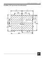
1
PanelMate
Power Series
Installation Guide
File Name: Eaton_PanelMate_PowerSeries_All_install_D99
2
PanelMate Power Series Installation Guide
Information in this manual is subject to change without notice and does not represent a
commitment on the part of Cutler-Hammer, Inc. Permission is granted to duplicate this
material without modification only for your use or the internal use of other members of your
company or your agents to assist you in the use and servicing of products purchased from
Cutler-Hammer. No permission is granted to modify this material or include this material in
a compilation.
PanelMate is a registered trademark of Cutler-Hammer, Inc.
Commercial names of products from other manufacturers or developers that appear in this
manual are registered or unregistered trademarks of those respective manufacturers or
developers, which have expressed neither approval nor disapproval of Cutler-Hammer
products.
Copyright Cutler-Hammer, Inc. 1999. All rights reserved.
P/N 01-00436-00
Preface
3
Preface
Support Services
Technical Support
It is Cutler-Hammer’s goal to
ensure your greatest
possible satisfaction with the
operation of our products.
We are dedicated to
providing fast, friendly, and
accurate assistance. That is
why we offer you so many
ways to get the support you
need. Whether it’s by phone,
fax, modem, or mail, you
can access Cutler-Hammer
support information 24
hours a day, seven days a
week.
If you are in the U.S. or Canada, you can take advantage of our toll-free line for technical
assistance with hardware and software product selection, system design and installation,
and system debugging and diagnostics. Technical support engineers are available for calls
during regular business hours (8 am - 5:30 pm EST) by calling 1-800-809-2772.
International calls can be made to either the Tech Line at 1-800-809-2772 (toll call) or the
Cutler-Hammer main business line at 614-882-3282.
Emergency Technical Support
1-800-809-2772
1-800-809-2772
Because machines do not run on a nine-to-five schedule, we offer emergency after-hours
technical support. A technical support engineer can be paged for emergencies involving
plant down situations or safety issues. Emergency support calls are automatically routed
directly to our answering service after-hours (5:30 pm - 8 am EST) and weekends. For
emergency technical support, call 1-800-809-2772.
Note that the Emergency Technical Support phone number does not currently support
product repairs or shipping outside normal business hours.
Technical Support Fax
614-882-0417
You can also contact our technical support engineers by faxing your support requests
directly to the Advanced Product Support Center (APSC) located in Westerville, Ohio at
614-882-0417.
Information Fax-Back Service
614-899-5323
The latest Cutler-Hammer product information, specifications, technical notes and
company news is available to you via fax through our direct document request service at
614-899-5323. Using a touch-tone phone, you can select any of the info faxes from our
automated product literature and technical document library, punch in a fax number and
receive the information immediately.
Website and
E-mail Address
http://www.cutlerhammer.eaton.com/automation
[email protected]
If you have Internet capabilities, you also have access to technical support via our website
at http://www.cutlerhammer.eaton.com/automation. The website includes technical notes,
frequently asked questions, release notes, and other technical documentation. This direct
technical support connection also offers you the ability to request assistance and exchange
software files electronically.
Technical support messages and files can be sent to [email protected].
4
PanelMate Power Series installation Guide
Bulletin Board Service
614-899-5209
Parameters: 8 data bits, 1 stop bit, parity none, 9600-28.8K baud
If you have modem access, you can dial in directly to our electronic bulletin board service
for the latest product and company information. File sharing, product software downloads
and our user message service are just a few of the things you will find online at
614-899-5209.
Software Update Service
1-800-809-2772
FAX 614-899-4141
We also offer you the opportunity to take advantage of software upgrades, advanced
software notices, and special software promotions through our Software Update Service.
When you register your software, you will receive one-year of free or reduced-price
upgrades along with all the other benefits of membership, including 48-hour shipping of
software upgrades. Contact the Software Update Service at 1-800-809-2772 or fax
614-899-4141.
Repair and Upgrade Service
614-882-3282 ext. 7601
FAX 614-882-3414
Our well-equipped Customer Service department is ready to assist you with repairs,
upgrades, and spare parts services. If a situation arises where one of these services is
needed, just call 614-882-3282 x7601 or fax 614-882-3414.
Product Ordering Service
614-882-3282
FAX 614-882-6532
Authorized Cutler-Hammer distributors may place product orders directly with our Order
Processing department by calling 614-882-3282 x406 or faxing 614-882-6532. For
information on your local distributor, call the Cutler-Hammer Tech Line.
Customer Support Center
1-800-356-1243
Authorized Cutler-Hammer distributors and Cutler-Hammer sales offices can get
assistance for Cutler-Hammer standard and component product lines through the
Customer Support Center. Call the Customer Support Center for the following assistance:
1.
Stock availability, proof of shipment, or to place an order.
2.
Expedite an existing order.
3.
Product assistance and product price information.
4.
Product returns other than warranty returns.
For information on your local distributor or sales office, call the Cutler-Hammer Tech Line
at 1-800-809-2772.
Correspondence Address
Cutler-Hammer
P.O. Box 6166
Westerville, OH 43086-6166
Shipping Address
Cutler-Hammer
173 Heatherdown Drive
Westerville, OH 43081
Table of Contents
Table of Contents
Chapter 1: Introduction .............................................................................................. 7
The Three Most Critical Installation Issues ................................................................... 8
Replacing Existing PanelMate Power Series Units ........................................................ 8
Chapter 2: Enlosure Selection .................................................................................... 9
Enclosure Rating......................................................................................................... 10
Enclosure Construction ............................................................................................... 10
Enclosure Sizing and Unit Positioning ........................................................................ 10
Chapter 3: Comm. Cable Selection, Shielding, Grounding & Termination ............ 13
RS-232 Communications ............................................................................................ 15
RS-232 Grounding Recommendations......................................................................... 15
RS-232 Shielding Recommendations........................................................................... 15
RS-422 Communications ............................................................................................ 16
RS-422 Grounding Recommendations......................................................................... 16
RS-422 Shielding Recommendations........................................................................... 16
RS-485 Multi-Drop Communications.......................................................................... 17
RS-485 Shielding Recommendations........................................................................... 17
Allen-Bradley DH-485 Communications..................................................................... 18
Allen-Bradley Data Highway/Data Highway Plus Communications............................. 19
Allen-Bradley Remote I/O Link Communications ....................................................... 20
GE Fanuc Genius I/O Communications....................................................................... 21
Modicon Modbus Plus Communications...................................................................... 22
DeviceNet Communications ........................................................................................ 23
Profibus DP Communications ..................................................................................... 24
Profibus DP Shielding Recommendations.................................................................... 24
Using PanelMate on a Profibus DP network ................................................................ 24
Chapter 4: Cable Segregation & Placement............................................................. 25
Cable Segregation ....................................................................................................... 26
Cable Placement ......................................................................................................... 26
Chapter 5: Replacing an Existing PanelMate Power Series Unit............................ 27
Replacing a 120VAC PMPS unit with another 120VAC PMPS unit............................ 28
Replacing a 120VAC PMPS unit with a 24VDC PMPS unit ....................................... 28
Upgrading a PMPS Model 1500 unit with a PMPS Model 1700 unit ........................... 29
Chapter 6: Cutout and Unit Dimensions .................................................................. 31
PanelMate 5000 Keypad Unit Dimensions .................................................................. 32
PanelMate 5000 Keyboard Cutout Dimensions............................................................ 33
PanelMate 5000 Split Architecture Unit Dimensions................................................... 34
PanelMate 5000 Split Architecture Cutout Dimensions ............................................... 35
PanelMate 5000 Touchscreen Unit Dimensions........................................................... 36
PanelMate 5000 Touchscreen Cutout Dimensions ....................................................... 37
PanelMate 4000 Keypad Unit Dimensions .................................................................. 38
PanelMate 4000 Keypad Cutout Dimensions............................................................... 39
PanelMate 4000 Split Architecture Unit Dimensions................................................... 40
5
6
PanelMate Power Series Installation Guide
PanelMate 4000 Split Architecture Cutout Dimensions................................................41
PanelMate 3000 Keyboard Unit Dimensions ................................................................42
PanelMate 3000 Keypad Cutout Dimensions................................................................43
PanelMate 3000 Touchscreen Unit Dimensions ...........................................................44
PanelMate 3000 Touchscreen Cutout Dimensions........................................................45
PanelMate 2000 Model 26xx Keyboard Unit Dimensions.............................................46
PanelMate 2000 Model 26xx Keyboard Cutout Dimensions .........................................47
PanelMate 2000 Model 24xx Keyboard Unit Dimensions.............................................48
PanelMate 2000 Model 24xx Keyboard Cutout Dimensions .........................................49
PanelMate 1700 Keyboard Unit Dimensions ................................................................50
PanelMate 1700 Keyboard Cutout Dimensions.............................................................51
PanelMate 1700 Touchscreen Unit Dimensions ...........................................................52
PanelMate 1700 Touchscreen Cutout Dimensions........................................................53
PanelMate 1500 Keyboard Unit Dimensions ................................................................54
PanelMate 1500 Keyboard Cutout Dimensions.............................................................55
PanelMate 1500 Touchscreen Unit Dimensions ...........................................................56
PanelMate 1500 Touchscreen Cutout Dimensions........................................................57
Chapter 1: Introduction
1
Introduction
7
8
PanelMate Power Series Installation Guide
The Three Most Critical Installation Issues
Thank You
for choosing the PanelMate
Power Series for your
operator interface. When
properly installed, your
PanelMate Power Series unit
will provide years of
dependable, trouble-free
operation in rugged industrial
environments.
With more than 100,000 PanelMate units currently in operation since its introduction in
1986, Cutler-Hammer has helped many users troubleshoot their PanelMate installations.
This Installation Guide is intended to help you avoid the common mistakes made by
first-time PanelMate users.
Three aspects of your installation are critical to long life and reliable operation:
Enclosure selection
Communication cable selection, shielding, grounding and termination
Cable segregation and placement.
This Installation Guide reviews each of these areas, providing recommendations and
guidelines for making knowledgeable installation decisions.
Replacing Existing PanelMate Power Series Units
If you are planning to replace an existing PanelMate Power Series unit with a new
PanelMate Power Series unit, there are several very important steps to take to ensure
proper operation. See Chapter 5: Replacing Existing PanelMate Units.
Chapter 2: Enclosure Selection
2
Enclosure Selection
9
10
PanelMate Power Series Installation Guide
Enclosure Rating
Chapter Overview
The enclosure for your
PanelMate unit must provide
protection against conditions
that can shorten the life of
your PanelMate or cause
improper operation:
•
Protection from oil, dust,
moisture, corrosive
vapors and other
airborne contaminants
•
Protection from ambient
temperatures above or
below unit specifications
•
Protection from
electromagnetic
interference
This chapter reviews
enclosure choice
considerations and provides
a guide for sizing your
PanelMate unit’s enclosure.
The front panels of PanelMate Power Series units provide a NEMA 4 or NEMA 12
rating when mounted in a correspondingly-rated enclosure. Some PanelMate models are
also rated for NEMA 4X installations. Make sure the enclosure you choose will meet or
exceed your application’s NEMA rating requirement.
Enclosure Construction
Cutler-Hammer recommends an enclosure constructed of cold rolled steel. This will help
guard your unit against electromagnetic interference, as well as provide proper structural
support and good heat dissipation.
Enclosure Sizing and Unit Positioning
Careful enclosure sizing is important for proper heat dissipation and easy installation
and maintenance. For efficient convection cooling, free space is needed around the
PanelMate unit. Convection cooling draws a vertical column of air upward over internal
circuitry through the vents in the unit. In all installations, the cooling air must not
exceed the maximum specified ambient temperature. This determination must be made
for the maximum expected plant temperature (maximum temperature of the air
surrounding the enclosure.)
•
•
Potential Problem
Areas
Enclosure is too small for
the operator interface –
not enough free space for
efficient convection
cooling
Enclosure is filled with
other heat-generating
devices – internal
temperature rises above
the operator interface’s
ratings
•
Maintain recommended free space above and below the PanelMate unit. (see
table on next page)
Avoid mounting other heat-generating equipment near the PanelMate unit. If
no other location is available, mount the equipment beside or behind the
PanelMate unit. If side/rear space is not available, it is preferable to mount the
other equipment above rather than below the PanelMate unit. Be sure to
maintain the recommended free space area between the PanelMate unit and the
other equipment.
Leave room for easy access to circuit boards, wiring/cable connections, and
regular maintenance.
Maintain Minimum
Recommended Clearance
Enclosure is mounted
near devices generating
high levels of magnetic or
electrical interference
Free air space is not present
around the outside of the
enclosure – prevents the
enclosure’s metal panels
from dissipating internal heat
Maintain Minimum
Recommended Clearance
Chapter 2: Enclosure Selection
Recommended Free Space
and Maximum Operating
Temperature Table
The free space area is the
space between the
PanelMate unit’s electronics
and the top or bottom of the
enclosure
PanelMate
Power Series
Model
Maximum Operating Ambient
Temperature
Unit Heat
Output
Recommended
Free Space
Above/Below Unit
1500 Series
50OC Gray scale & Color TFT
40OC Color Dual-scan
41 BTU/hr
(12W)
2” minimum
1700 Series
50OC Grayscale & Color TFT
40OC Color Dual-scan
78 BTU/hr
(23W)
2” minimum,
4” recommended
2000 Series
Grayscale
50OC
188
BTU/hr
(55 W)
6” minimum
2000 Series
Color
50OC
273
BTU/hr
(80 W)
6” minimum
3000 Series
Grayscale &
Color Dualscan
Internal fans help provide a
uniform ambient temperature
inside the enclosure
11
40OC
119
BTU/hr
(35W)
6” minimum
3000 Series
Color TFT
50OC
119
BTU/hr
(35W)
6” minimum
4000 Series
50OC
273
BTU/hr
(80W)
6” minimum
5000 Series
50OC
137
BTU/hr
(40W)
6”minimum
If the inside temperature of the enclosure is above the PanelMate unit’s recommended
range (see table), you must use filtered fans, heat exchangers, or air conditioners to lower
the temperature. Because hot air rises to the top of an enclosure, the temperature inside
can vary greatly from bottom to top. A fan can be used to circulate air within the
enclosure to maintain a more uniform temperature. Make sure the magnetic properties of
the equipment used to cool the enclosure do not interfere with your PanelMate unit’s
operation. CRT monitors are especially susceptible to magnetic fields.
Note:
If an air-purged enclosure is used, it is recommended that the inside/outside
pressure differential not exceed .5 PSI.
The following sizing table is offered as an aid in the selection of enclosures to be used
with PanelMate products. Cutler-Hammer offers no guarantee or warranty to the specific
applicability of this table as actual conditions may vary and methods of the use of our
products are beyond our control. For specific information about enclosure selection and
cooling methods, contact your enclosure vendor.
Note:
Cutout and unit dimensional information for all PanelMate Power Series units is
provided in Appendix A.
12
PanelMate Power Series Installation Guide
Enclosure Size vs.
Average Internal
Temperature Rise
This table makes the
following assumptions:
PanelMate Model
Enclosure Size
Avg. Internal Temp. Rise
1500 w/keypad
16x16x4
16x16x6
20x16x6
12x12x4
12x12x6
12x14x6
16x16x4
16x16x6
20x16x6
12x12x6
12x14x6
24x20x12
24x24x12
30x24x12
24x20x12
24x24x12
30x24x12
24x20x8
24x24x8
30x24x16
30x24x20
36x30x16
30x24x8
30x24x10
24x24x8
24x24x10
24x30x8
6.8o C
6.2o C
5.6o C
11.4o C
10.8o C
9.8o C
10.8o C
9.3o C
7.7o C
14.4o C
12.8o C
10o C
8.9o C
7.2o C
15o C
12.8o C
10.6o C
7.2o C
6.7o C
9.4o C
8.3o C
6.6o C
6.o C
5.6o C
7.2o C
6.7o C
6.1o C
•
Enclosure is fabricated
from cold rolled steel
1500 w/touchscreen
•
All sides of the
enclosure are
uninsulated (free
standing)
1700 w/keypad or touchscreen
•
•
Recommended
minimum clearance
between the PanelMate
unit and the top and
bottom of the enclosure
No other heat-generating
equipment is installed in
the enclosure
Note: The temperature rise
shown represents the
temperature rise in the
enclosure above the outside
temperature. For example: if
the temperature outside the
o
enclosure in 35 C and the
temperature rise in the
o
enclosure is 10 C, then the
average temperature inside
o
the enclosure will be 45 C.
1700 w/touchscreen
2000 Gray Scale
2000 Color
All 3000
All 4000
5000 w/ keypad
5000 w/touchscreen
Chapter 3: Communication Cable Selection
3
Communication Cable
Selection, Shielding,
Grounding & Termination
13
14
PanelMate Power Series Installation Guide
Chapter Overview
This chapter contains a
summary of seven popular
communication interface
options. Each summary
provides specific
recommendations,
guidelines and installation
tips
Potential Problem
Areas
Improper grounding of
communications cable,
causing excessive
radiated emissions
Incorrect cable or pinout
Improper or lack of
termination on PanelMate
units located at the end of
a communications
network
Failure to maintain
minimum/maximum cable
lengths between nodes on
a communications
network
Exceeding recommended
cable or total network
distance
A variety of communication interface options are available for PanelMate Power Series
products. Options include:
•
RS-232 and RS-422 based communications
•
RS-485 multi-drop communications
•
“Open” multi-drop networks (examples: DeviceNet, Profibus)
•
Proprietary PLC networks (examples: A-B Data Highway, Genius I/O, Modbus
Plus)
Cutler-Hammer does not recommend any specific communications option. Your choice
should be based on the requirements of your total control system. The communications
option you choose determines the precautions you need to take when installing and
connecting your PanelMate Power Series unit.
For easy reference, this chapter contains a summary of seven popular communication
interface options. Each summary provides specific recommendations, guidelines and
installation tips.
Note:
Low signal level conductors (Category 2) have a low tolerance for induced
electrical noise. Electrical noise can cause a wide range of communications
problems resulting in slow or error-prone PanelMate operation. Be certain to
follow all of the installation recommendations for the communication option
you choose. Also, be sure to follow good wiring placement practices as outlined
in Chapter 4: Cable Segregation and Placement.
Chapter 3: Communication Cable Selection
15
RS-232 Communications
Recommended
Distance
Up to 50 feet
Recommended Cable
Type/Size
24 gauge, shielded pair
RS-232 Grounding Recommendations
Grounding of the communication cable shield at both ends will provide the most
immunity to high frequency electrical interference. However, the introduction of low
frequency interference by high ground currents in the shield may require grounding only
one end. Should this approach result in unacceptable high frequency interference, then
an RS-422 interface should be considered. For RS-232 communications, the maximum
rated input voltage at the PanelMate unit’s serial port is –30 to +30V.
RS-232 Shielding Recommendations
Application: Short or Long Runs in LOW or HIGH Noise Environment with
INSIGNIFICANT Levels of Low Frequency Ground Differential Voltage Between
Connected Units
A good quality shielded cable consisting of twisted pairs for the required communication
wires and logic common is recommended. An unshielded line is not recommended
because the unshielded connectors may act as an antenna resulting in radiated emissions
that may exceed the CE required limit. Additionally, shielded cable provides greater
ESD protection. The shield should be connected directly to the chassis of the
interconnected units at both ends. The connector housing should contact the cable shield
uniformly around the entire 360-degree periphery of the housing cable entry opening.
Never connect the shield by way of a drain wire pigtail unless absolutely necessary. If a
pigtail is required, the shield should be terminated as close as possible to the connector
to minimize the pigtail length.
Application: Short or Long Runs in LOW Noise Environment with HIGH Levels of
Low Frequency Ground Differential Voltage Between Connected Units
A good quality shielded cable consisting of twisted pairs for the required communication
wires and logic common is recommended. The shield should be connected directly to
the chassis of one of the interconnected units (one end only). Never connect the shield
by way of a drain wire pigtail unless absolutely necessary. If a pigtail is required, the
shield should be terminated as close as possible to the connector to minimize the pigtail
length.
Application: Short or Long Runs in HIGH Noise Environment with HIGH Levels of
Low Frequency Ground Differential Voltage Between Connected Units
A good quality shielded cable consisting of twisted pairs for the required communication
wires and logic common is recommended. The shield should be connected directly to
the chassis of one of the interconnected units and ac-coupled through a 0.01 mf capacitor
at the other end to the chassis of the second unit. The connector housing should contact
the cable shield uniformly around the entire 360-degree periphery of the housing cable
entry opening. Attaching the capacitor at the ac-coupled end will require some ingenuity
to achieve a secure connection at both the shield and chassis while keeping the capacitor
lead length as short as possible.
16
PanelMate Power Series Installation Guide
RS-422 Communications
Recommended
Distance
Up to 4000 feet
Up to 2000 feet for RS-422
connected to A-B Channel 0
Recommended Cable
Type/Size
22 gauge, shielded pair
RS-422 Grounding Recommendations
This balanced interface will operate with common mode DC or peak AC voltages
differentials of –7 to +7 volts between grounds at each end of the cable. In cases where
the common mode voltage approaches either extreme, the system may operate properly
when the shield is grounded at only one end of the cable. However, this arrangement
will make the system susceptible to high frequency interference. If the systems will not
operate properly due to high frequency interference and grounding the cable shield at
both ends is ineffective, then total isolation must be considered or eliminate ground
potentials in your plant.
RS-422 Shielding Recommendations
Application: Short or Long Runs in LOW or HIGH Noise Environment with
INSIGNIFICANT Levels of Low Frequency Ground Differential Voltage Between
Connected Units
A good quality shielded cable consisting of twisted pairs for the required communication
wires and logic common is recommended. An unshielded line is not recommended
because the unshielded connectors may act as an antenna resulting in radiated emissions
that may exceed the CE required limit. Additionally, shielded cable provides greater
ESD protection. The shield should be connected directly to the chassis of the
interconnected units at both ends. The connector housing should contact the cable shield
uniformly around the entire 360-degree periphery of the housing cable entry opening.
Never connect the shield by way of a drain wire pigtail unless absolutely necessary. If a
pigtail is required, the shield should be terminated as close as possible to the connector
to minimize the pigtail length.
Application: Short or Long Runs in LOW Noise Environment with HIGH Levels of
Low Frequency Ground Differential Voltage Between Connected Units
A good quality shielded cable consisting of twisted pairs for the required communication
wires and logic common is recommended. The shield should be connected directly to
the chassis of one of the interconnected units (one end only). Never connect the shield
by way of a drain wire pigtail unless absolutely necessary. If a pigtail is required, the
shield should be terminated as close as possible to the connector to minimize the pigtail
length.
Application: Short or Long Runs in HIGH Noise Environment with HIGH Levels of
Low Frequency Ground Differential Voltage Between Connected Units
A good quality shielded cable consisting of twisted pairs for the required communication
wires and logic common is recommended. The shield should be connected directly to the
chassis of one of the interconnected units and ac coupled through a 0.01 mf capacitor at
the other end to the chassis of the second unit. The connector housing should contact the
cable shield uniformly around the entire 360-degree periphery of the housing cable entry
opening. Attaching the capacitor at the ac-coupled end will require some ingenuity to
achieve a secure connection at both the shield and chassis while keeping the capacitor
lead length as short as possible.
Note:
When using RS-422 communications, it may be necessary to modify your
communications wiring when replacing an existing PanelMate operator station
with a new unit. Refer to Chapter 5: Replacing Existing PanelMate Units for
additional information.
Chapter 3: Communication Cable Selection
17
RS-485 Multi-Drop Communications
Recommended
Distance
Up to 4000 feet
Up to 2000 feet for RS-485
connected to A-B Channel 0
Recommended Cable
Type/Size
22 gauge, shielded pair
Note: See separate section
for Allen-Bradley DH-485
Communications
This network is an extension of RS-422 and is used for the distribution of data between
multiple system components and peripherals over distances up to 4000’. This system
will tolerate common mode voltage differentials from –7 to +12 volts. For more
information refer to the EIA RS-485 Standard.
RS-485 Shielding Recommendations
Application: Short or Long Runs in LOW or HIGH Noise Environment with
INSIGNIFICANT Levels of Low Frequency Ground Differential Voltage Between
Connected Units
A good quality shielded cable consisting of twisted pairs for the required communication
wires and logic common is recommended. An unshielded line is not recommended
because the unshielded connectors may act as an antenna resulting in radiated emissions
that may exceed the CE required limit. Additionally, shielded cable provides greater
ESD protection. The shield should be connected directly to the chassis of the
interconnected units at both ends. The connector housing should contact the cable shield
uniformly around the entire 360-degree periphery of the housing cable entry opening.
Never connect the shield by way of a drain wire pigtail unless absolutely necessary. If a
pigtail is required, the shield should be terminated as close as possible to the connector
to minimize the pigtail length.
Application: Short or Long Runs in LOW Noise Environment with HIGH Levels of
Low Frequency Ground Differential Voltage Between Connected Units
A good quality shielded cable consisting of twisted pairs for the required communication
wires and logic common is recommended. The shield should be connected directly to
the chassis of one of the interconnected units (one end only). Never connect the shield
by way of a drain wire pigtail unless absolutely necessary. If a pigtail is required, the
shield should be terminated as close as possible to the connector to minimize the pigtail
length.
Application: Short or Long Runs in HIGH Noise Environment with HIGH Levels of
Low Frequency Ground Differential Voltage Between Connected Units
A good quality shielded cable consisting of twisted pairs for the required communication
wires and logic common is recommended. The shield should be connected directly to
the chassis of one of the interconnected units and ac coupled through a 0.01 mf capacitor
at the other end to the chassis of the second unit. The connector housing should contact
the cable shield uniformly around the entire 360-degree periphery of the housing cable
entry opening. Attaching the capacitor at the ac-coupled end will require some ingenuity
to achieve a secure connection at both the shield and chassis while keeping the capacitor
lead length as short as possible.
Note:
When using RS-485 communications, it may be necessary to modify your
communications wiring when replacing an existing PanelMate operator station
with a new unit. Refer to Chapter 5: Replacing Existing PanelMate Units for
additional information.
18
PanelMate Power Series Installation Guide
Allen-Bradley DH-485 Communications
Recommended Cable
Type/Size
Belden 9842 cable
Tip #1: All PanelMate units on the A-B DH-485 communications network should have
optical isolation to prevent serial port damage. If the PanelMate model you are
installing DOES NOT have built-in optical isolation, then an Allen-Bradley
AIC module should be used to provide optical isolation. See Replacing
Existing PanelMate Units Using R422/485 Communications for specific
PanelMate model optical isolation information.
Tip #2: Verify the network is terminated. Both ends of a DH-485 network must contain
termination resistors. PanelMate Power Series units have built in termination
resistors that can be activated if needed.
PanelMate Power Series 1500: on the RJ-45 connector, jumping pins 7 and 8
activates 120-Ohm AC termination
All 120VAC PanelMate Power Series Models: Jumpers on the processor board
terminate the serial port. Jumper “JP1” for serial port 1 must be set in position
A for 120 Ohm termination
All 24VDC PanelMate Power Series Models (except 1500): An external switch
is located on the bottom of the unit.
24V
+ -
Note:
KYSW
120AC
Ω
120Ω
220Ω
NONE
/RS232
SERIAL PORT 1
3 4
SERIAL PORT 2
120AC
Ω
120Ω
220Ω
NONE
/RS232
N/C
AUDIO
3 4
1 2
Up to 4000 feet
Refer to your Allen-Bradley Cable Installation manual for detailed information. The
following tips are useful when installing a PanelMate on A-B DH-485 communication
networks:
1 2
Recommended
Distance
FAULT RELAY
When using A-B DH-485 communications, it may be necessary to modify your
communications wiring when replacing an existing PanelMate operator station
with a new unit. Refer to Chapter 5: Replacing Existing PanelMate Units for
additional information.
Chapter 3: Communication Cable Selection
Recommended
Distance
Allen-Bradley Data Highway/Data Highway Plus
Communications
Up to 10,000 feet at
57.6Kbaud. Shorter lengths
at higher baud rates
Data Highway and Data Highway Plus are proprietary communication networks of
Allen-Bradley. Generally, the structure and components of the two networks are the
same, but there are differences in communications protocols. Refer to your AllenBradley Cable Installation Manual for detailed information.
Recommended Cable
Type/Size
The following tips are useful when installing a PanelMate on A-B Data Highway and
Data Highway Plus communication networks:
Belden 9463 “blue hose”
twinaxial cable
19
Tip #1: Verify the network is terminated. Both ends of an A-B Data Highway/Data
Highway Plus network must contain termination resistors. Resistor value is
determined by the network baud rate. The resistor value must be the same at
both ends of the network:
57.6 K, 115.2K
230.4K
150 or 82.5 Ohm
82.5 Ohm
Tip #2: The minimum cable length is 20’ between any two nodes.
Tip #3: On Data Highway Plus networks, daisy chained networks are preferred, but
trunkline/drop line is acceptable. Star or tree configurations are NOT
acceptable.
Tip #4: In order to comply with CE Mark requirements, ferrite cores must be installed
on the PanelMate unit’s AcceleratI/On cable. Steward number 28B0735-000 is
recommended. Refer to Cutler-Hammer’s PanelMate AcceleratI/On Interface
Installation I.L. for installation details.
20
PanelMate Power Series Installation Guide
Allen-Bradley Remote I/O Link Communications
Recommended
Distance
Up to 10,000 feet at
57.6Kbaud. Shorter lengths
at higher baud rates
Recommended Cable
Type/Size
PVC Twinaxial cable
The Remote I/O Link is a proprietary communication network of Allen-Bradley. The
following tips are useful when installing a PanelMate on Remote I/O Link networks:
Tip #1: Verify the network is terminated. Both ends of an A-B Remote I/O Link
network must be terminated. Resistor value is determined by the network baud
rate. The resistor value must be the same at both ends of the network:
57.6 K, 115.2K
230.4K
150 or 82.5 Ohm
82.5 Ohm
Tip #2: On Remote I/O networks, daisy chained networks are preferred, but
trunkline/drop line is acceptable. Star or tree configurations are NOT
acceptable.
Tip #3: All devices connected to the Remote I/O Link must communicate at the same
baud rate.
Chapter 3: Communication Cable Selection
21
GE Fanuc Genius I/O Communications
Recommended
Distance
Up to 7500 feet at
38.4Kbaud. Shorter lengths
at higher baud rates
This proprietary communications network uses twisted pair shielded cable and/or fiber
optics cable. For detailed installation instructions refer to the GE Fanuc Automation
Genius I/O Systems and Communications User’s Manual. The following tips are useful
when installing a PanelMate on Genius I/O communication networks:
Recommended Cable
Type/Size
Tip #1: If the PanelMate unit is located at an end of the network, termination is
required. The termination resistor value is dependent on the type of cable used.
Consult your Genius I/O manual for exact requirements.
Refer to your GE Fanuc
Automation Genius I/O
Systems and
Communications User’s
Manual
Tip #2: Cable type, baud rate and cable length must all be compatible and determine
the maximum number of nodes allowed on the network.
Tip #3: Shield Out and Shield In connections must be daisy chained, with the first
device’s Shield In terminal and the last device’s Shield Out terminal left
unconnected.
Tip #4: In high electrical noise installations, 153.6Kbaud provides better noise
immunity.
22
PanelMate Power Series Installation Guide
Modicon Modbus Plus Communications
Recommended
Distance
Up to 7500 feet at
38.4Kbaud. Shorter lengths
at higher baud rates
Recommended Cable
Type/Size
Refer to your GE Fanuc
Automation Modicon
Modbus Plus Network
Planning and Installation
Guide
This proprietary communications network consists of twisted pair shielded cable
extending up to 1500 feet with up to 32 nodes. For detailed installation instructions refer
to your Modicon Modbus Plus Network Planning and Installation Guide. The following
tips are useful when installing a PanelMate on Modicon Modbus Plus communication
networks:
Tip #1: Trunkline/drop line is the only acceptable network configuration. Star or tree
configurations are NOT acceptable.
Tip #2: A drop cable is used to connect the PanelMate unit to the trunk line tap. The
drop cable is equipped with a ground lug that must be connected to PanelMate
unit’s panel ground.
Tip #3: The minimum cable length between nodes must be at least 10’.
Chapter 3: Communication Cable Selection
23
DeviceNet Communications
Recommended
Distance
Up to 1640 feet at 125Kbaud
Recommended Cable
Type/Size
Refer to your CutlerHammer DeviceNet
Installation Guide
DeviceNet is a non-proprietary communications network consisting of 5 conductor,
shielded cable in trunk line (thick) and drop line (thin) styles. Up to 64 nodes can be
installed on the network. Refer to Cutler-Hammer’s DeviceNet Planning and Installation
Guide for detailed information on DeviceNet networks. The following tips are useful
when installing a PanelMate on a DeviceNet communication network:
Tip #1: The drop line to the PanelMate unit must not exceed 20’.
Tip #2: If the PanelMate unit is the last node on the network, termination is required.
Install a 120 Ohm terminator in the unused plug of the connector, or install a
120 Ohm resistor between pins 4 and 2 of the Phoenix connector.
Tip #3: The PanelMate unit does not draw power from, or supply power to the network.
It is not necessary to make the V+ connection, but you should do so to secure
the wires and prevent shorting.
Tip #4: In all PanelMate units, the DeviceNet signal ground is isolated from chassis
ground. In locations where problems are caused by high electrical noise, you
can change the jumper setting on the PanelMate unit’s DeviceNet
communications card to connect signal ground to chassis ground. Refer to
Cutler-Hammer’s PanelMate DeviceNet Interface Installation I.L. for detailed
jumper information.
Tip #5: In order to comply with CE Mark requirements, ferrite cores must be installed
on the PanelMate unit’s drop line. Steward number 28B1020-100 is
recommended for thick line installations. Steward number 28B0735-000 is
recommended for thin line installations. Refer to Cutler-Hammer’s PanelMate
DeviceNet Interface Installation I.L. for installation details.
24
PanelMate Power Series Installation Guide
Profibus DP Communications
Recommended
Distance
Up to 3278 feet at
93.7Kbaud
Profibus DP is based on RS-485 network technology. A Profibus DP network may have
up to 126 nodes, but maximum length of the network is determined by baud rate.
Profibus DP Shielding Recommendations
Recommended Cable
Type/Size
22 gauge, shielded pair
A good quality shielded cable consisting of twisted pairs for the required communication
wires and logic common is recommended. An unshielded line is not recommended
because the unshielded connectors may act as an antenna resulting in radiated emissions
that may exceed the CE required limit. Additionally, shielded cable provides greater
ESD protection. The shield should be connected directly to the chassis of the
interconnected units at both ends. The connector housing should contact the cable shield
uniformly around the entire 360-degree periphery of the housing cable entry opening.
Never connect the shield by way of a drain wire pigtail unless absolutely necessary. If a
pigtail is required, the shield should be terminated as close as possible to the connector
to minimize the pigtail length.
Using PanelMate on a Profibus DP network
The following tips are useful when installing a PanelMate on a Profibus DP
communication network:
Tip #1: The Profibus network must be terminated at both ends of every segment. The
termination must be powered at all times.
Tip #2: As the Profibus DP network allows daisy-chained connections, wiring for
Signal A and Signal B must remain consistent throughout the segment. It is
suggested that the green wire is used for Signal A and the red wire is used for
Signal B.
Chapter 4: Cable Segregation & Placement
4
Cable Segregation &
Placement
25
26
PanelMate Power Series Installation Guide
Cable Segregation
Chapter Overview
When planning the location
and placement of wiring,
care should be taken to
minimize electrical noise
problems. Noise is often the
problem when intermittent
communications problems
are experienced. Loss of
data, slow response and
communication error
messages are common
indications of electrical noise
contamination.
This chapter gives a brief
overview of cable routing
and placement issues.
The low power cabling used for PLC and PC-based control systems is very susceptible to
electrical noise generated by high power conductors. Even when protected by conduit,
noise can interfere with your communication lines and networks. Therefore it is
important to segregate conductors according to their type.
Category
Description
Examples
Category 1
High Power Conductors
These conductors can cause
electrical noise in Category 2
conductors when in close
proximity. Are more tolerant of
electrical noise than Category 2.
AC power lines
High power digital AC and DC
lines
Reference: NEC article 725 class 1
Reference IEEE level 3 and 4
Category 2
Potential Problem
Areas
Reference NEC article 725 class 2,
class 3
Reference IEEE level 1 and level 2
High and low power
conductors routed in the
same conduit or raceway
Conduit with low power
conductors routed in close
parallel proximity to
conduit containing high
power conductors
Low Signal Level Conductors
These conductors are less tolerant
of electrical noise, however, they
cause less noise in adjacent
conductors.
Typically these conductors are
used to connect hard-contact
switches, relays, solenoids,
motors, generators and arc
welders.
Communication cables Ethernet, PLC networks, etc.
Low power digital AC and DC
I/O lines
Typically these conductors are
used to connect PLCs and related
modules with PanelMate operator
stations
Cable Placement
The following guidelines should be used when installing your communication cables:
Cable or PanelMate unit
located too close to
devices generating high
levels of magnetic or
electrical interference
•
All Category 2 cables should be shielded and routed in a separate conduit
or raceway from Category 1 cables.
•
Route Category 2 cables at least one foot from 120VAC power lines.
•
Route Category 2 cables at least two feet from 240VAC power lines.
Lack of continuous
electrical continuity along
the length of the conduit
installation
•
Route Category 2 cables at least three feet from 480VAC power lines.
•
Route Category 2 cables at least five feet from high voltage enclosures.
•
If a Category 2 cable must cross Category 1 cables, it should cross at a
right angle.
•
If Category 2 cable is enclosed in metal conduit or a metal raceway,
electrical continuity must be maintained along the entire length of the
conduit/raceway installation, including entry into the enclosure.
Chapter 5: Replacing an Existing PanelMate Power Series Unit
5
Replacing an Existing
PanelMate Power Series
Unit
27
28
PanelMate Power Series Installation Guide
Chapter Overview
Replacing a 120VAC PanelMate Power Series unit with another
120VAC PanelMate Power Series unit.
When replacing and existing
PanelMate Power Series unit
with a new PanelMate Power
Series unit, it may be
necessary to modify your
installation. This chapter will
help you determine if
modifications are required.
The only issue to investigate in this retrofitting is enclosure size. Be sure to confirm the
expected enclosure ambient temperature with the new unit installed. The table in
Chapter 2: Enclosure Sizing can help you determine the suitability of the existing
enclosure. Also, confirm that the minimum free space above and below the new unit will
meet the requirements for the model installed. See the table provided in Chapter 2:
Enclosure Sizing.
Replacing a 120VAC PanelMate Power Series unit with a
24VDC PanelMate Power Series unit
Potential Problem
Areas
Existing enclosure is too
small for the new
PanelMate unit
Different power supply
requirements for the new
PanelMate unit
Optically vs. non-optically
isolated serial ports
When replacing a 120VAC unit with a 24VDC unit, there are two issues to address: The
need for a 24VDC power supply, and the PLC Communications cable. The power supply
issue is self-explanatory. The communications issues discussed apply to all 24VDC
PanelMate Power Series models except 1500 models.
Proprietary Networks or DeviceNet Communications: These communications cables
use a special connector and attach to an optional communications module or board.
Since they do not use the PanelMate unit’s serial ports, modifications are not necessary.
Simply plug in the existing cable’s connector into the new unit’s optional
communications module.
RS-232 Communications: An RS-232 cable is already equipped with the ground return
conductor required by the 1700’s optically isolated serial ports.
RS-422/485/DH-485 Communications : When connected to an optically isolated serial
port, an RS-422/485/DH-485 cable must have a ground return conductor. You can
approach this issue from two directions: provide a ground wire, or defeat the optical
isolation on the serial ports. Without the modifications, the new 24VDC PanelMate
Power Series unit may experience unreliable communications and unexpected
operational failures.
Option #1: If the existing cable was installed without a ground conductor but
contains an unused conductor, that conductor can be connected and the cable shield
connection revised to conform with the noise reduction recommendations provided
in Chapter 3: Communication Cable Selection, Shielding Grounding and
Termination.
Option #2: Replace the existing communication cable with a new cable. CutlerHammer offers communications cables for these applications. Contact Cutler
Hammer Support Services for additional information.
Option #3: Place a jumper in the existing cable connector between the Ground Pin
(5) and the connector shell cover. This would provide the required ground reference
for the new 24VDC unit, but the port would now be non-isolated. If the existing
unit functioned properly with a non-isolated port, the new unit will probably work
equally as well with this modification.
Chapter 5: Replacing an Existing PanelMate Power Series Unit
29
Upgrading a PanelMate Power Series Model 1500 unit with a
PanelMate Power Series Model 1700 unit
When upgrading a Model 1500 unit to a Model 1700 unit, three issues should be
reviewed: power supply, enclosure sizing, and communications cable.
Power Supply: Although both PanelMate Power Series 1500 and 1700 models operate
on 24VDC, 1700 models draw additional current. Check to make sure your 24VDC
power supply is adequately rated for the 1700.
Enclosure Sizing: Due to the 1700’s higher current usage, it produces more BTUs of
heat energy that must be dissipated by the enclosure. The table in Chapter 2: Enclosure
Sizing can help you determine the suitability of the existing enclosure.
Communications Cable: Model 1700 units are equipped with optically isolated serial
ports using DB-9 connectors. Model 1500 units are equipped with non-optically isolated
serial ports using RJ-type connectors. These issues are addressed differently, depending
on the type of communications used.
Proprietary Networks or DeviceNet Communications: These communications cables
use a special connector and attach to an optional communications module. Since they do
not use the 1700’s serial ports, modifications are not necessary. Simply plug in the
existing cable’s connector into the 1700s units optional communications module
RS-232 Communications: An RS-232 cable is already equipped with the ground return
conductor required by the 1700’s optically isolated serial ports. Therefore, the only
modification required to the cable is changing from the RJ-type connector to a DB-9
connector. An adapter is available from Cutler-Hammer, or the existing connector can
be removed and replaced with a new DB-9 connector.
RS-422/485/DH-485 Communications : When connected to an optically isolated serial
port, an RS-422/485/DH-485 cable must have a ground return conductor. You can
approach this issue from two directions: provide a ground wire, or defeat the optically
isolation on the serial ports. Without the modifications, the new1700 unit may
experience unreliable communications and unexpected operational failures.
Caution:
You can not simply add a
DB-9 to RJ adapter when
using RS-422/485/DH-485
communications. You must
jumper the existing cable
connector as described.
Otherwise, the serial ports
will remain optically isolated
and you may experience
unreliable communications
and unexpected operational
failures.
Option #1: If the existing cable was installed without a ground conductor but contains
an unused conductor, that conductor can be connected and the cable shield connection
revised to conform with the noise reduction recommendations provided in Chapter 3:
Communication Cable Selection, Shielding Grounding and Termination.
If you elect to use this option, you will need to remove the existing RJ connector and
replace it with a DB-9 connector.
Option #2: Replace the existing communication cable with a new cable. Cutler-Hammer
offers communications cables for these applications. Contact Cutler Hammer Support
Services for additional information.
Option #3: Place a jumper in the existing cable connector between the Ground Pin (5)
and the connector shell cover. This would provide the required ground reference for the
new 24VDC unit, but the port would now be non-isolated. If the existing unit functioned
properly with a non-isolated port, the new unit will probably work equally as well with
this modification.
If you elect to use this option, you will need to remove the existing RJ connector and
replace it with a DB-9 connector.
30
PanelMate Power Series Installation Guide
Appendix A: Cutout and Unit Dimensions
A
Cutout and Unit
Dimensions
Before you begin cutting metal........
The information in this Appendix was accurate at the time of printing.
However, product dimensions and cutouts are subject to change.
A Cutout Drawing is included with your PanelMate Power Series unit.
Confirm all of your cutout dimensions with that drawing prior to cutting.
31
32
PanelMate Power Series Installation Guide
PanelMate 5000 Keypad Unit Dimensions
19.00
(482.60)
19.22
(488.19)
C
A
N
C
E
L
3
1
2
4
5
6
7
8
9
0
6.40
(162.56)
0.90
(22.86)
11.74
(298.20)
17.34
(440.44)
Appendix A: Cutout and Unit Dimensions
PanelMate 5000 Keyboard Cutout Dimensions
7.50
8.70
8.70
(220.98)
(220.98)
9.27
(235.46)
7.50
(190.50)
(190.50)
2.50
2.50
(63.50)
(63.50)
4.00
(101.60)
8.87
(225.30)
4.13
(104.90)
Cutout
4.13
(104.90)
8.87
(225.30)
9.27
(235.46)
4.00
(101.60)
.25 Dia. Hole
(6.35)
9.16
(232.66)
9.16
(232.66)
33
34
PanelMate Power Series Installation Guide
PanelMate 5000 Split Architecture Unit Dimensions
13.96
(354.58)
0.05 (Ref.)
(1.27)
5.22
(132.59)
19.00
(482.60)
6.40
(162.56)
1.08 (27.43)
11.75
(298.45)
Appendix A: Cutout and Unit Dimensions
PanelMate 5000 Split Architecture Cutout Dimensions
8.80
1.66
8.80
(223.52)
(42.16)
5.00
(127.00)
1.66
(223.52)
2.50
(63.50)
2.50
(63.50)
(42.16)
5.00
(127.00)
1.00
(25.40)
.25 Dia. Slot
(6.35)
3.50
(88.90)
6.22
(157.99)
2.00
(50.80)
2.00
(50.80)
Cutout
6.22
(157.99)
.25 Dia. Hole
3.50
(6.35)
(88.90)
1.00
(25.40)
Minimum 9.75 (247.65)
Maximum 27.00 (685.80)
8.82
8.82
(224.03)
(224.03)
1.19
(30.23)
2.13
.22 Dia. Hole
1.13
(54.10)
(5.59)
(28.70)
1.13
Cutout
(28.70)
1.19
2.13
(54.10)
(30.23)
5.00
1.66
(42.16)
(127.00)
2.50
2.50
(63.50)
(63.50)
5.00
(127.00)
1.66
(42.16)
35
36
PanelMate Power Series Installation Guide
PanelMate 5000 Touchscreen Unit Dimensions
15.00
(381.00)
13.42
(340.87)
6.43
(163.32)
0.80 (20.32)
10.87
(276.10)
Appendix A: Cutout and Unit Dimensions
PanelMate 5000 Touchscreen Cutout Dimensions
5.50
7.16
7.16
(181.86)
(181.86)
(139.70)
1.90
1.90
(48.26)
(48.26)
5.50
(139.70)
.25 Dia. Slot
(6.35)
5.25
(133.35)
6.26
(159.00)
6.37
(161.80)
1.75
(44.45)
1.75
6.37
(44.45)
(161.80)
Cutout
12.52
.25 Dia. Hole
(6.35)
5.25
(133.35)
6.90
13.80
(350.52)
(175.26)
(318.01)
37
38
PanelMate Power Series Installation Guide
PanelMate 4000 Keypad Unit Dimensions
19.00
(482.60)
19.22
(488.19)
C
A
N
C
E
L
1
2
4
5
3
6
7
8
9
0
15.50
(393.70)
0.96 (24.38)
17.26
(438.04)
Appendix A: Cutout and Unit Dimensions
PanelMate 4000 Keypad Cutout Dimensions
7.50
8.70
8.70
(220.98)
(220.98)
9.27
(235.46)
7.50
(190.50)
(190.50)
2.50
2.50
(63.50)
(63.50)
4.00
(101.60)
8.87
(225.30)
4.13
(104.90)
Cutout
4.13
(104.90)
8.87
(225.30)
9.27
(235.46)
4.00
(101.60)
.25 Dia. Hole
(6.35)
9.16
(232.66)
9.16
(232.66)
39
40
PanelMate Power Series Installation Guide
PanelMate 4000 Split Architecture Unit Dimensions
13.96
(354.58)
0.05 (Ref.)
(1.27)
5.22
(132.59)
19.00
(482.60)
0.92 (23.37)
12.06
(306.32)
15.50
(393.70)
Appendix A: Cutout and Unit Dimensions
PanelMate 4000 Split Architecture Cutout Dimensions
8.80
1.66
8.80
(223.52)
(42.16)
5.00
(127.00)
1.66
(223.52)
2.50
(63.50)
2.50
(63.50)
(42.16)
5.00
(127.00)
1.00
(25.40)
.25 Dia. Slot
(6.35)
3.50
(88.90)
6.22
(157.99)
2.00
(50.80)
2.00
(50.80)
Cutout
6.22
(157.99)
.25 Dia. Hole
3.50
(6.35)
(88.90)
1.00
(25.40)
Minimum 9.75 (247.65)
Maximum 27.00 (685.80)
8.82
8.82
(224.03)
(224.03)
1.19
(30.23)
2.13
.22 Dia. Hole
1.13
(54.10)
(5.59)
(28.70)
1.13
Cutout
(28.70)
1.19
2.13
(54.10)
(30.23)
5.00
1.66
(42.16)
(127.00)
2.50
2.50
(63.50)
(63.50)
5.00
(127.00)
1.66
(42.16)
41
42
PanelMate Power Series Installation Guide
PanelMate 4000 Touchscreen Unit Dimensions
15.00
(381.00)
13.42
(340.87)
17.94
(455.68)
4.52
(114.81)
10.26
2.37
(260.60)
(60.20)
2.37
(60.20)
15.50
(393.70)
0.96 (24.38)
17.26
(438.04)
43
Appendix A: Cutout and Unit Dimensions
PanelMate 4000 Touchscreen Cutout Dimensions
5.50
7.16
7.16
(181.86)
(181.86)
(139.70)
1.90
1.90
(48.26)
(48.26)
5.50
(139.70)
.25 Dia. Slot
(6.35)
5.25
(133.35)
6.26
(159.00)
6.37
(161.80)
1.75
(44.45)
1.75
6.37
(44.45)
(161.80)
Cutout
12.52
.25 Dia. Hole
(6.35)
5.25
(133.35)
6.90
13.80
(350.52)
(175.26)
(318.01)
44
PanelMate Power Series Installation Guide
PanelMate 3000 Keyboard Unit Dimensions
13.50
(342.90)
13.00
(330.20)
5.15
(130.81)
0.65
(16.51)
11.75
(298.45)
Appendix A: Cutout and Unit Dimensions
PanelMate 3000 Keypad Cutout Dimensions
6.47
6.47
(164.34)
(164.34)
4.50
4.50
(140.46)
(140.46)
1.50
1.50
(38.10) (38.10)
6.22
6.00
(157.99)
(152.40)
4.50
(140.46)
1.50
(38.10)
12.00
(304.80)
1.50
(38.10)
Cutout
4.50
(140.46)
.22 Dia. Slot
(5.59)
6.22
6.00
(152.40)
(157.99)
.22 Dia. Hole
(5.59)
6.25
6.25
(158.75)
(158.75)
12.50
(317.50)
45
46
PanelMate Power Series Installation Guide
PanelMate 3000 Touchscreen Unit Dimensions
12.30
(312.42)
11.97
(304.04)
5.40
(137.16)
5.14
(130.56)
1.21
(30.73)
10.22
(259.59)
Appendix A: Cutout and Unit Dimensions
47
PanelMate 3000 Touchscreen Cutout Dimensions
5.87
5.87
(149.10)
5.70
5.70
(144.78)
.22 Dia. Hole
(5.59)
(149.10)
(144.78)
4.65
4.65
(118.11)
(118.11)
1.55
1.55
(39.37)
(39.37)
5.70
(144.78)
4.50
(114.30)
5.48
(139.19)
1.50
(38.10)
11.01
(279.65)
1.50
(38.10)
5.53
Cutout
(140.46)
4.50
(114.30)
5.70
(144.78)
.22 Dia. Slot
(5.59)
11.40
(289.56)
48
PanelMate Power Series Installation Guide
PanelMate 2000 Model 26xx Keyboard Unit Dimensions
11.50
(292.10)
13.10
(332.74)
10.52
9.84
(267.21)
(249.94)
0.68 (17.27)
11.80
(299.72)
Appendix A: Cutout and Unit Dimensions
PanelMate 2000 Model 26xx Keyboard Cutout Dimensions
5.47
5.47
(138.94)
(138.94)
4.50
4.50
(114.30)
(114.30)
1.50
1.50
(38.10)
(38.10)
4.95
6.05
(125.73)
(153.67)
6.27
(159.26)
1.65
(41.91)
12.10
(146.41)
1.65
(41.91)
Cutout
4.95
(125.73)
6.27
(159.26)
.22 Dia. Hole
(5.59)
5.31
10.62
(269.75)
(134.87)
.22 Dia. Slot
(5.59)
49
50
PanelMate Power Series Installation Guide
PanelMate 2000 Model 24xx Keyboard Unit Dimensions
11.50
(292.10)
12.00
(304.80)
10.48
9.80
(266.19)
(248.92)
0.66 (16.76)
10.72
(272.29)
Appendix A: Cutout and Unit Dimensions
PanelMate 2000 Model 24xx Keyboard Cutout Dimensions
5.47
5.47
(138.94)
(138.94)
4.50
4.50
(114.30)
1.50
1.50
(114.30)
(38.10) (38.10)
.22 Dia. Hole
(5.59)
.22 Dia. Slot
(5.59)
4.50
5.50
(114.30)
(139.70)
5.72
(145.29)
1.50
(38.1)
1.50
Cutout
(38.1)
5.72
11.00
(145.29)
(279.40)
4.50
(114.30)
5.31
10.62
(269.75)
(134.87)
51
52
PanelMate Power Series Installation Guide
PanelMate 1700 Keyboard Unit Dimensions
12.00
(304.80)
11.00
(279.40)
3.73*
(94.74)
1.10
(27.94)
1.66
(42.16)
6.36
(161.54)
4.20
(106.68)
Optional
Fieldbus
Module
2.75
(69.85)
Appendix A: Cutout and Unit Dimensions
PanelMate 1700 Keyboard Cutout Dimensions
5.70
5.70
(144.78)
(144.78)
4.00
4.00
(101.60)
(101.60)
.201 Dia. Hole
(5.11)
5.20
5.00
(132.08)
(127.00)
4.00
(101.60)
Cutout
10.00
(254.00)
4.00
(101.60)
5.20
(132.08)
5.50
(139.70)
11.00
(279.40)
53
54
PanelMate Power Series Installation Guide
PanelMate 1700 Touchscreen Unit Dimensions
10.51
(266.95)
7.63
(193.80)
3.73*
(94.74)
0.63 (17.27)
6.36
(161.54)
4.20
(106.68)
2.75
(69.85)
Optional
Fieldbus
Module
Appendix A: Cutout and Unit Dimensions
PanelMate 1700 Touchscreen Cutout Dimensions
4.91
4.91
(124.71)
(124.71)
3.26
3.26
(82.80)
(82.80)
3.47
3.25
(88.14)
.187 Dia. Hole
1.65
(4.75)
(41.91)
1.50
(38.10)
(82.55)
6.50
Cutout
(165.10)
3.47
(88.14)
4.69
9.38
(238.25)
(119.13)
55
56
PanelMate Power Series Installation Guide
PanelMate 1500 Keyboard Unit Dimensions
12.00
(304.80)
11.00
(279.40)
3.48*
(88.39)
1.10
(27.94)
1.66
(42.16)
6.36
(161.54)
4.20
(106.68)
Optional
Fieldbus
Module
2.50
(63.50)
Appendix A: Cutout and Unit Dimensions
PanelMate 1500 Keyboard Cutout Dimensions
5.70
5.70
(144.78)
(144.78)
4.00
4.00
(101.60)
(101.60)
.201 Dia. Hole
(5.11)
5.20
5.00
(132.08)
(127.00)
4.00
(101.60)
Cutout
10.00
(254.00)
4.00
(101.60)
5.20
(132.08)
5.50
(139.70)
11.00
(279.40)
57
58
PanelMate Power Series Installation Guide
PanelMate 1500 Touchscreen Unit Dimensions
10.51
266.95
7.63
193.80
3.47*
(88.14)
0.63 (17.27)
6.37
(161.80)
4.20
(106.68)
2.48
(62.99)
Optional
Fieldbus
Module
Appendix A: Cutout and Unit Dimensions
PanelMate 1500 Touchscreen Cutout Dimensions
4.91
4.91
(124.71)
(124.71)
3.26
3.26
(82.80)
(82.80)
3.47
3.25
(88.14)
.187 Dia. Hole
1.65
(4.75)
(41.91)
1.50
(38.10)
(82.55)
6.50
Cutout
(165.10)
3.47
(88.14)
4.69
9.38
(238.25)
(119.13)
59