1
Control Valves - SMARTLINK® MRV
10-30.7-5
E - i - 3/14
50120624-001/
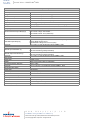
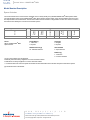
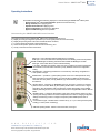
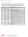
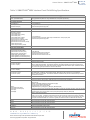
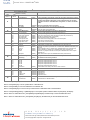
Specifications of SMARTLINK® MRV
SMARTLINK® MRV System Specifications
(For all Interface Panel configurations with factory-wired relay interface modules and power supply)
Position Accuracy
0.1 degrees (measured on the valve actuator shaft)
Number of Valves
1, 2, 3, or 4
22 field-adjustable positions for each valve including individual standby, purge and
Valve Commissioning Profile
light-off positions
Firing Rate Command
4-20 mA isolated input; 4.8V burden @ 20 mA
Firing Rate Feedback
4-20 mA isolated output; 400 ohm max load
24 VDC universal power supply; provides 24 VDC output to all system components
24 VDC within components
1 valve system: 36 W max
Power
2 valve system: 61 W max
3 valve system: 90 W max
4 valve system: 118 W max
Optional power supply 120-230 VAC provides 24 VDC to system
Low to High Fire Modulation Speed
20, 40, or 60 seconds (user selectable)
Temperature Range (Ambient)
All components except user display: -40°F to 158°F
NEMA 4X, IP66 (valve actuator)
Enclosure Ratings
NEMA 4X, IP66 (Optional MAXON-supplied enclosures with rail mounted components. See page 10-30.7-6 for individual components ratings)
FM Class I, Division 2: Groups A,B,C,D,T4 (when provided with specialized NEMA 4X
enclosures) (valve actuator also Class II, Division 2; Groups E, F, G)
ATEX Approval; II 3 G Ex nA nC IIC T4 Ta=-40C to +70C; IP66 when components
mounted in enclosure (valve actuator is II 3 G Ex nA nC IIC T4 Ta=-40C to +70C; IP66
and II 3 D Ex tD A22 T135C) and IEC Ex nA nC IIC T4 Ta=70C Gc, Ex tC IIIC T135C
Dc
Approvals
UL (US & Canadian): Air Fuel Ratio System and Limit Controls (UL353), Class 2 Software (UL 1998)
CE Gas Appliance Directive: Gas-Air Ratio Controller, Class C Software (prEN 120672, EN298)
CE EMC Directive: Electromagnetic Immunity and Emissions (EN61000)
CE Low Voltage Directive: Electrical Safety (EN61010-1)
Form A (N.O.), Dry Contacts
Relay Outputs
Contact Ratings: 250VAC/DC @ 12 A
Relay Inputs
120VAC, 230VAC, or 24VDC solid-state
w w w . m a x o n c o r p . c o m
combustion systems for industry
Maxon reserves the right to alter specifications and data without prior notice.
© 2014 Copyright Maxon Corporation. All rights reserved.
10-30.7-6
E - i - 3/14
Control Valves - SMARTLINK® MRV
50120624-001/
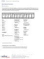
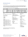
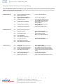
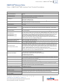
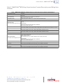
SMARTLINK® MRV Component Specifications
Control Interface
Power Input
Firing Rate Command
Spare Current Input
Firing Rate Feedback
Relay Driver Outputs
Digital Inputs
Wiring Terminals
Enclosure
Relay Output Interface
24VDC, 0.1 A
4-20 mA isolated input; 4.8V burden @ 20 mA
4-20 mA isolated input; 4.8V burden @ 20 mA
4-20 mA isolated input: 40 Ohm max load
Open collector, 30 VDC & 100 mA (max)
5-24VDC @ 10 mA (max)
Keyed, plug-type screw terminals; Terminals accept 14-24 gauge wire
1” W x 4.65” H x 3.85” D DIN rail-mounted, NEMA 1, IP20
Electromechanical Output Relays (6)
Enclosure
Relay Input Interface
Solid State Input Relays (6)
Enclosure
Network Interface
Network Input Connection (1)
Network Output Connections (7)
Enclosure
User Display
Power Input
Display
Temperature Range (Ambient)
Enclosure
Universal Power Supply
Power Input
Power Output
Enclosure
Valve-Actuator Assembly
Power Input
Torque
Maximum Travel Time
Enclosure (Actuator)
Dry Contacts: Form A (normally-open)
Max Contact Voltage: 250 VAC/DC
Max Contact Current: 12 A (continuous)
1” W x 4.65” H x 3.85” D DIN rail-mounted, NEMA 1, IP20
Input On-State Voltage: 120VAC, 230VAC or 24VDC depending on model
Input on-State Current: 25 mA
Input Off-State Leakage Current: 4 mA (max)
1” W x 4.65” H x 3.85” D DIN rail-mounted, NEMA 1, IP20
24VDC field device power & common
Data communication (polarity insensitive)
24VDC field device power & common
Data communication (polarity insensitive)
1” W x 4.65” H x 3.85” D DIN rail-mounted, NEMA 1, IP20
24VDC, 0.13 A
4 line x 20 character, back-lit, LCD display
-20°F to 122°F
5.5” H x 4.25” W x 1.75” D DIN rail-mounted, NEMA 1, IP50
120-230 VAC
24VDC, 6 A (max)
5.0” H x 2.12” W x 5.0” D DIN rail-mounted, NEMA 1, IP20
24VDC, 25W max
300 in-lbs (33.9 N.m)
14 seconds (open to close)
7.69” H x 4.4” W x 4.4” D, NEMA 4X, IP66
w w w . m a x o n c o r p . c o m
combustion systems for industry
Maxon reserves the right to alter specifications and data without prior notice.
© 2014 Copyright Maxon Corporation. All rights reserved.
Control Valves - SMARTLINK® MRV
10-30.7-7
E - i - 3/14
50120624-001/
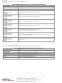
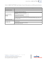
Table of Contents
Butterfly Valves:
Model Number Description............................................................................................. 10-30.7-8
Capacities and Specifications ........................................................................................ 10-30.7-9
Dimensions .................................................................................................................... 10-30.7-14
Ball Valves:
Model Number Description............................................................................................. 10-30.7-21
Capacities and Specifications ........................................................................................ 10-30.7-22
Dimensions .................................................................................................................... 10-30.7-25
Control Actuator:
Model Number Description............................................................................................. 10-30.7-31
Dimensions .................................................................................................................... 10-30.7-31
Spare Actuator:
Model Number Description............................................................................................. 10-30.7-34
Control Interface:
Model Number Description............................................................................................. 10-30.7-35
Dimensions .................................................................................................................... 10-30.7-36
User Display:
Model Number Description............................................................................................. 10-30.7-41
w w w . m a x o n c o r p . c o m
combustion systems for industry
Maxon reserves the right to alter specifications and data without prior notice.
© 2014 Copyright Maxon Corporation. All rights reserved.
10-30.7-8
E - i - 3/14
Control Valves - SMARTLINK® MRV
50120624-001/
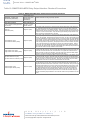
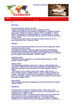
Model Number Description
Butterfly Valves
The model number shown on the valve nameplate can accurately identify every MAXON SMARTLINK® MRV Butterfly Valve. The
example below shows a typical SMARTLINK® MRV Butterfly Valve model number, along with the available choices for each item
represented in the model number. The first three choices determine the valve's configured item number. The next eight characters
in the model number identify valve body and actuator options.
1
Size
0100 - 1"
0125 - 1.25"
0150 - 1.5"
0200 - 2"
0250 - 2.5"
0300 - 3"
0400 - 4"
0600 - 6"
0800 - 8"
1000 - 10"
1200 - 12"
1400 - 14"
1600 - 16"
-
Body Connection
A - ANSI Flange
M - "M" Style Flange
X - Special
* - Actuator Only
Body Seals
A - Buna-N
B - Viton
X - Special
* - Actuator Only
Flow Capacity
S - Standard
Series
SRCV - SMARTLINK® MRV Butterfly
Valve
Body Material
1 - Cast Iron
2 - Carbon Steel
3 - Brass
5 - Stainless Steel
X - Special
* - Actuator Only
Valve
Number
1
Language
A
Software
Version
A
-
Torque
Rating
Body
Internals
SRCV
Body
Material
Series
S
Actuator
Body
Seals
Flow
Capacity
0100
Valve Body
Body
Connection
Valve
Size
Configured Item Number
1
1E
A
0
Torque Rating
1 - 300 in-lbs
X - Special
* - Valve Body Only
Software Version [1]
1E - Standard software
** - Valve Body Only
Language
A - English
X - Special
* - Valve Body Only
Valve Number
0 - Valve 0
1 - Valve 1
2 - Valve 2
3 - Valve 3
4 - Spare Actuator
Body Internals
1 - Trim Package 1
2 - Trim Package 1, Oxy Clean
5 - Trim Package 2
6 - Trim Package 2, Oxy Clean
X - Special
* - Actuator Only
[1] The latest version is the default.
Trim Package Options and Typical Materials:
1 - 300 Series Stainless Steel stem, 300 Series Stainless Steel disc and Bronze bushings
2 - 300 Series Stainless Steel stem, 300 Series Stainless Steel disc and PEEK bushings
w w w . m a x o n c o r p . c o m
combustion systems for industry
Maxon reserves the right to alter specifications and data without prior notice.
© 2014 Copyright Maxon Corporation. All rights reserved.
Control Valves - SMARTLINK® MRV
10-30.7-9
E - i - 3/14
50120624-001/
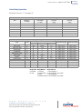
Valve Body Capacities
Butterfly Valves - 1” through 4”
Size
1”
1.25”
1.5”
2”
2.5”
3”
4”
Butterfly Valve Body Performance Table - 1” through 4”
Minimum
Maximum Inlet
Maximum
Controllable
Pressure
Cv Rating
Cv rating
(psig)
27
0.50
100
70
0.60
100
105
0.70
100
190
1.30
100
260
2.40
90
360
3.00
60
750
5.00
30
Fluid
Gas
Code
158F/70C Max Air
Butane Gas
Coke Oven Gas
Digester Gas
Landfill Gas
Manufactured Gas
Natural Gas
Oxygen
Propane Gas
Propane/Butane Blend Gas
Refinery Gas
Sour Natural Gas
Town Gas
A
D
E
F
G
H
I
J
K
L
M
N
O
Maximum Body
Pressure
(psig)
100
100
100
100
100
100
100
Butterfly Valve Body Fluid Table - 1” through 4”
Suggested Material Options
Maximum Fluid
Maximum Ambient
Body Seals
Body Material Body Internals Temperature Rating Temperature Rating
A,B
A,B
B
B
B
B
A,B
B
A,B
A,B
B
B
A,B
1,2,3,5
1,2,3,5
1,2,5
5
5
5
1,2,3,5
3,5
1,2,3,5
1,2,3,5
5
5
5
Body Seals Body Material
A- Buna-N
1- Cast Iron
B- Viton
2- Carbon Steel
3- Brass
5- Stainless Steel
w w w . m a x o n c o r p . c o m
combustion systems for industry
Maxon reserves the right to alter specifications and data without prior notice.
© 2014 Copyright Maxon Corporation. All rights reserved.
1,5
1,5
1,5
5
5
5
1,5
2,6
1,5
1,5
5
5
5
158°F (70°C)
158°F (70°C)
158°F (70°C)
158°F (70°C)
158°F (70°C)
158°F (70°C)
158°F (70°C)
158°F (70°C)
158°F (70°C)
158°F (70°C)
158°F (70°C)
158°F (70°C)
158°F (70°C)
Body Internals
1- Trim Package 1
2- Trim Package 1, Oxy Clean
5- Trim Package 2
6- Trim Package 2, Oxy Clean
158°F (70°C)
158°F (70°C)
158°F (70°C)
158°F (70°C)
158°F (70°C)
158°F (70°C)
158°F (70°C)
158°F (70°C)
158°F (70°C)
158°F (70°C)
158°F (70°C)
158°F (70°C)
158°F (70°C)
10-30.7-10
E - i - 3/14
Control Valves - SMARTLINK® MRV
50120624-001/
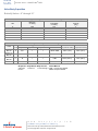
Valve Body Capacities
Butterfly Valves - 6” through 16”
Butterfly Valve Body Performance Table - 6” through 16”
Minimum
Maximum
Controllable
Cv Rating
Cv Rating
1425
12.5
2500
22
4500
35
6400
50
8800
67
11700
88
Size
6”
8”
10”
12”
14”
16”
Fluid
158F/70C
Max Air
350F/177C
Max Air
400F/204C
Max Air
Natural Gas
Maximum Inlet
Pressure
(psig)
5
5
5
5
5
5
Butterfly Valve Body Fluid Table - 6” through 16”
Suggested Material Options
Gas
Maximum Fluid
Maximum Ambient
Code Body Seals Body Material
Body Internals
Gasket Material Temperature Rating Temperature Rating
A
A,B
1
1
NEOP, FIBR
158°F (70°C)
158°F (70°C)
B
B
1
1
FIBR
350°F (177°C)
158°F (70°C)
C
B
1
1
FIBR
400°F (204°C)
140°F (60°C)
I
A,B
1
1
NEOP, FIBR
158°F (70°C)
158°F (70°C)
Body Seals Body Material Body Internals
Gasket Material
A- Buna-N 1- Cast Iron
1- Trim Package 1 FIBR - Hi Temp Fiber Gasket
B- Viton
NEOP- Neoprene Gasket
w w w . m a x o n c o r p . c o m
combustion systems for industry
Maxon reserves the right to alter specifications and data without prior notice.
© 2014 Copyright Maxon Corporation. All rights reserved.
10-30.7-11
E - i - 3/14
Control Valves - SMARTLINK® MRV
50120624-001/
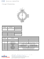
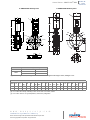
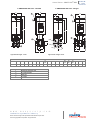
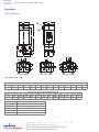
Valve Body Assembly Specifications
1” through 4” Butterfly Valves
2
6
8
4
9
7
12
1
8
10
11
3
7
8
5
Item No.
Description
1
Valve Body
Item No.
7
8
9
1
Cast Iron
ASTM A159 Gr. 3000
Body Materials
Material Code
2
Carbon Steel
ASTM A216 Gr. WCB
3
Brass
ASTM B62
UNS No. C83600
5
Stainless Steel
ASTM A351 Gr. CF8M
Body Seals
Description
Material
O-Ring
Standard material options are
O-Ring
Buna-N and Viton
O-Ring
Trim Package Materials
Item No.
Description
2
3
4
5
6
10
11
12
Valve Stem
Butterfly Disc
Top Bushing
Bottom Bushing
Top Shim Bushing
Screw
Washer
Retaining Ring
Internal Trim Package
1
2
303 Stainless Steel, ASTM A157 Gr. G3000
304 Stainless Steel (1.4301), ASTM A240 Type 304 UNS No. S30400
Bronze
ASTM B271, B505 and B584
UNS No. C93200
w w w . m a x o n c o r p . c o m
combustion systems for industry
Maxon reserves the right to alter specifications and data without prior notice.
© 2014 Copyright Maxon Corporation. All rights reserved.
18-8 Stainless Steel
304 Stainless Steel (1.4301)
316 Stainless Steel
PEEK
10-30.7-12
E - i - 3/14
Control Valves - SMARTLINK® MRV
50120624-001/
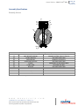
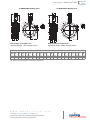
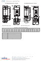
6” through 16” Butterfly Valves
2
5
6
11
7
4
10
1
8
9
3
4
12
Body Materials
Item No.
Description
1
Valve Body
Item No.
6
7
Material Code
1
Cast Iron
ASTM A159 Gr. 3000
Body Seals
Description
Material
O-Ring
Standard material options
are Buna-N and Viton
O-Ring
Trim Package Materials
Item No.
2
Description
Valve Size
Valve Stem
3
Butterfly Disc
4
5
8
9
10
11
12
Top & Bottom Bushing
Shim Bushing
Screw
Washer
Retaining Ring
Retaining Ring
Pipe Plug
Internal Trim Package
1
6” & 8”
10” through 16”
316 Stainless Steel, ASTM A276
304 Stainless Steel (1.4301)
Carbon Steel
ASTM A167 UNS No. S30400
ASTM A108 UNS No. G10180
Bronze
ASTM B271, B505 and B584 UNS No. C93200
304 Stainless Steel (1.4301)
316 Stainless Steel
Zinc Plated Carbon Steel
Zinc Plated Carbon Steel
Carbon Steel
SAE 1060-1090 UNS No. G10600-G10900
Alloy Steel, ASTM A322 UNS G40370
w w w . m a x o n c o r p . c o m
combustion systems for industry
Maxon reserves the right to alter specifications and data without prior notice.
© 2014 Copyright Maxon Corporation. All rights reserved.
Control Valves - SMARTLINK® MRV
10-30.7-13
E - i - 3/14
50120624-001/
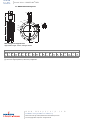
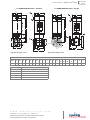
Assembly Specifications
Butterfly Valves
3A
8A
6A
7A
10A
4A
9A
5A
2A
1A
11A
4A
SMARTLINK® Valve Body Assembly Material Specifications
Item No.
Description
1A
2A
3A
4A*
5A
6A
7A
8A
9A
10A
11A*
Valve Body Sub-assembly
Locating Spring Pin
Adapter Bracket
Socket Head Cap Screw
Coupling
Locking Collar
Spring Pin
Dowel Pin
Hard Stop Screw
Hard Stop Nut
Cover Plate
*These items used only on sizes 1” through 4”
w w w . m a x o n c o r p . c o m
combustion systems for industry
Maxon reserves the right to alter specifications and data without prior notice.
© 2014 Copyright Maxon Corporation. All rights reserved.
SMARTLINK® Component Material Specifications
Assembly per pages 10-30.7-11 and -12
Zinc Plated Carbon Steel
ASTM B179 T6 Aluminum
Zinc Plated Carbon Steel
ASTM A582 Type 303 Stainless Steel
Zinc Plated Alloy Steel
Zinc Plated Carbon Steel
303 Stainless Steel
18-8 Stainless Steel
Stainless Steel
Aluminum
10-30.7-14
E - i - 3/14
Control Valves - SMARTLINK® MRV
50120624-001/
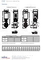
Dimensions
1” SMARTLINK® Butterfly Valve
B
1.25” SMARTLINK® Butterfly Valve
I
B
I
C
C
H
H
D
D
G
G
JØ
E
O
JØ
E
O
KØ
LØ
A
LØ
N
F
A
NMØ
F
KØ
MØ
Q
Q
Q
R
P
Flange Dimension “A” (in inches)
Threaded
2.87
Threaded
3.15
Steel
Socket Welded
2.84
Threaded
2.81
Brass
Solder Cup
3.51
Approximate weight: 22 lbs; w/flanges 26 lbs
B
C
D
E
1.0
1.25
4.0
4.0
2.0
2.0
10.2
10.2
3.0
3.5
R
P
Iron
Size
Q
Flange Dimension “A” (in inches)
Threaded
3.05
Threaded
3.12
Steel
Socket Welded
3.05
Threaded
3.05
Brass
Solder Cup
3.63
Iron
Approximate weight: 25 lbs; w/flanges 29 lbs
Dimensions in inches unless stated otherwise
H
J
K
L
M
F
G
I
NPT
Ø
Ø
Ø
Ø
2.9 12.2 0.5
4.4 0.62 4.2
3.1
1.1
3.2 12.7 0.5
4.4 0.62 5.0
3.5
1.4
N
O
P
Q
2.5
2.7
45°
45°
1.31
1.31
1
1
[1] M8 - 1.25 tap, 0.62 deep, 2 holes
w w w . m a x o n c o r p . c o m
combustion systems for industry
Maxon reserves the right to alter specifications and data without prior notice.
© 2014 Copyright Maxon Corporation. All rights reserved.
R
[1]
0.62
0.62
10-30.7-15
E - i - 3/14
Control Valves - SMARTLINK® MRV
50120624-001/
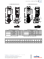
1.5” SMARTLINK® Butterfly Valve
2” SMARTLINK® Butterfly Valve
B
B
I
C
I
C
H
H
D
D
G
G
JØ
JØ
E
KØ
O
E
LØ
A
F
KØ
O
LØ
N
A
F
N
MØ
MØ
Q
Q
Q
R
P
P
Size
B
C
D
E
1.5”
2”
4.0
4.0
2.0
2.0
10.2
10.2
3.5
3.5
Approximate weight: 31 lbs; w/flanges 39 lbs
[1] M8 - 1.25 tap, 0.62 deep, 2 holes
w w w . m a x o n c o r p . c o m
Maxon reserves the right to alter specifications and data without prior notice.
© 2014 Copyright Maxon Corporation. All rights reserved.
1"
Iron
Dimension in inches unless stated otherwise
H
J
K
L
F
G
I
NPT
Ø
Ø
Ø
3.2 12.7 0.5
4.4 0.62 5.0
3.9
3.4 12.7 0.5
4.4 0.75 6.0
4.8
combustion systems for industry
R
Flange Dimension “A” (in inches)
Threaded
3.43
Threaded
3.56
Steel
Socket Welded
3.51
Threaded
3.72
Brass
Solder Cup
4.62
Flange Dimension “A” (in inches)
Threaded
3.27
Threaded
3.23
Steel
Socket Welded
3.24
Threaded
3.15
Brass
Solder Cup
3.88
Iron
Approximate weight: 28 lbs; w/flanges 34 lbs
Q
M
Ø
1.7
2.2
N
O
P
Q
2.8
3.0
45°
45°
1.31
1.69
1
1
R
[1]
0.62
0.62
10-30.7-16
E - i - 3/14
Control Valves - SMARTLINK® MRV
50120624-001/
2.5” SMARTLINK® Butterfly Valve
3” SMARTLINK® Butterfly Valve
B
I
C
B
H
I
C
H
D
D
G
G
JØ
KØ
JØ
O
E
MØ
E
MØ
A
N
F
A
LØ
Q
LØ
N
F
Q
KØ
O
R
Q
Q
R
P
P
Flange Dimension “A” (in inches)
Threaded
3.72
Threaded
3.67
Steel
Socket Welded
3.79
Threaded
3.80
Brass
Solder Cup
5.27
Iron
Approximate weight: 39 lbs; w/flanges 58 lbs
Size
B
C
D
E
2.5”
3”
4.0
4.0
2.0
2.0
10.2
10.2
4.0
4.0
Flange Dimension “A” (in inches)
Threaded
3.83
Threaded
4.13
Steel
Socket Welded
4.03
Threaded
4.02
Brass
Solder Cup
5.09
Iron
Approximate weight: 44 lbs; w/flanges 62 lbs
Dimensions in inches unless stated otherwise
H
J
K
L
M
F
G
I
NPT
Ø
Ø
Ø
Ø
4.2 13.2 0.5 4.4 0.75 7.5
5.5
2.6
4.2 13.2 0.5 4.4 0.75 7.5
6.0
3.3
N
O
P
Q
3.8
3.8
45°
45°
1.81
1.81
1
1
[1] M8 - 1.25 tap, 0.62 deep, 2 holes
w w w . m a x o n c o r p . c o m
combustion systems for industry
Maxon reserves the right to alter specifications and data without prior notice.
© 2014 Copyright Maxon Corporation. All rights reserved.
R
[1]
0.62
0.62
Control Valves - SMARTLINK® MRV
10-30.7-17
E - i - 3/14
50120624-001/
4” SMARTLINK® Butterfly Valve
6” SMARTLINK® Butterfly Valve
B
I
C
B
H
I
C
H
D [3]
D
G
G
KØ
LØ
MØ
MØ
KØ
JØ
E
E
LØ
O
N
A
F
JØ
O
F
N
Q
Q
S
T
R
P
P
R
P
P
Q
P
Q
Flange Dimension “A” (in inches )
Iron
Threaded
4.13
Threaded
4.06
Steel
Socket Welded
4.06
Approximate weight: 49 lbs; w/flanges 71 lbs
Approximate weight: 55 lbs; w/flanges 71 lbs
Dimensions in inches unless stated otherwise
G
H
K
L
M
N
I
J
[3] NPT
Ø
Ø
Ø
Ø
Size
B
C
D
[3]
E
F
4”
6”
4.0
2.0
10.2
4.6
5.3
13.8
0.5
4.4
0.75
9.0
7.5
4.3
4.0
2.0
10.2
5.9
5.9
15.1
0.5
4.4
[1]
8.9
7.75
6.1
[1] 1/2-13 UNC, 6 holes
[2] For 4” Valve: M8-1.25 tap, 0.62 deep, 2 holes. For 6” Valve: 1/2-13 UNC, 6 holes
[3] For 6” Valve: Add 2.5” for high temperature (>158°F/70°C) configuration
w w w . m a x o n c o r p . c o m
combustion systems for industry
Maxon reserves the right to alter specifications and data without prior notice.
© 2014 Copyright Maxon Corporation. All rights reserved.
Q
R
[2]
O
P
S
T
4.9
22.5°
2.06
1
0.62
---
---
6.1
60°
1.0
3.0
0.438
1.5
4.3
10-30.7-18
E - i - 3/14
Control Valves - SMARTLINK® MRV
50120624-001/
8” SMARTLINK® Butterfly Valve
A
10” SMARTLINK® Butterfly Valve
J
B
I
B
C [4]
A
J
I
C [4]
H
PØ
H
KØ
N
OØ
D
KØ
UØ
R
D
PØ
R
S
OØ
T
R
NØ
L
L
R
T
Q
E
E
M
F
S
R
M
F
G
R
G
R
T
R
T
Note: Flanges are shipped loose
Approximate weight: 66 lbs; w/flanges 139 lbs
Approximate weight: 61 lbs; w/flanges 91 lbs
Dimensions in inches unless stated otherwise
H
I
K
O
G
J
L
M
N
[4] NPT
Ø
Ø
Size
A
B
C
[4]
8”
4.0
2.0
10.2
7.0
7.4
1.5
4.4
16.2
0.5
4.4
10.25
1.1
7.6
[1]
10”
4.0
2.0
10.2
9.2
7.6
2.5
6.5
18.4
0.5
4.4
14.2
3.6
8.4
[2]
[1]
[2]
[3]
[4]
D
E
F
P
Ø
Q
R
S
[3]
T
8.0
11.8
60°
1.0
0.438
3.0
---
10.0
16.0
---
1.0
0.438
3.0
13
1/2-13 UNC, 6 holes
1.0 diameter, 12 holes
Through holes
Add 2.5” for high temperature (>158°F/70°C) configuration
w w w . m a x o n c o r p . c o m
combustion systems for industry
Maxon reserves the right to alter specifications and data without prior notice.
© 2014 Copyright Maxon Corporation. All rights reserved.
U
Ø
10-30.7-19
E - i - 3/14
Control Valves - SMARTLINK® MRV
50120624-001/
12” SMARTLINK® Butterfly Valve
B
A
14” SMARTLINK® Butterfly Valve
J
B
I
A
I
J
C [2]
C [2]
PØ
KØ
H
PØ
NØ
S
UØ
D
R
R
R
R
OØ
L
KØ
H
T
R
R
T
R
OØ
D
R
S
UØ
T
L
T
NØ
2
E
E
M
F
G
M
F
G
Note: Flanges are shipped loose.
Approximate weight: 77 lbs; w/flanges 197 lbs
Note: Flanges are shipped loose.
Approximate weight: 109 lbs; w/flanges 266 lbs
Dimensions in inches unless stated otherwise
H
I
K
N
F
G
J
L
M
[2] NPT
Ø
Ø
Size
A
B
C
[2]
12”
4.0
2.0
10.2
10.2
8.7
3.0
7.6
19.4
0.5
4.4
17.0
4.6
9.5
1.0
12.0
19.0
1.0
0.438
3.0
16.0
14”
4.0
2.0
10.2
11.4
9.6
3.0
7.6
20.6
0.5
4.4
18.8
5.8
10.5
1.1
13.2
21.0
1.0
0.438
3.0
17.4
D
E
[1] 4 holes through
[2] Add 2.5” for high temperature (>158°F/70°C) configuration
w w w . m a x o n c o r p . c o m
combustion systems for industry
Maxon reserves the right to alter specifications and data without prior notice.
© 2014 Copyright Maxon Corporation. All rights reserved.
O
Ø
P
Ø
R
S
[1]
T
U
Ø
10-30.7-20
E - i - 3/14
Control Valves - SMARTLINK® MRV
50120624-001/
16” SMARTLINK® Butterfly Valve
B
A
J
I
C [2]
PØ
H
KØ
S
D
R
R
R
R
UØ
OØ
L
T
T
NØ
E
F
G
M
Note: Flanges are shipped loose.
Approximate weight: 134 lbs; w/flanges 343 lbs
Size
A
B
C
[2]
D
E
F
16”
4.0
2.0
10.2
12.2
10.5
3.0
Dimensions in inches unless stated otherwise
H
I
K
N
G
J
L
M
[2] NPT
Ø
Ø
8.1
21.4
0.5
4.4
21.2
6.6
11.4
1.12
O
Ø
P
Ø
R
S
[1]
T
U
Ø
15.0
23.5
1.0
0.438
3.0
19.4
[1] 4 holes through
[2] Add 2.5” for high temperature (>158°F/70°C) configuration
w w w . m a x o n c o r p . c o m
combustion systems for industry
Maxon reserves the right to alter specifications and data without prior notice.
© 2014 Copyright Maxon Corporation. All rights reserved.
Control Valves - SMARTLINK® MRV
10-30.7-21
E - i - 3/14
50120624-001/
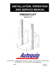
Model Number Description
Ball Valves
The model number shown on the valve nameplate can accurately identify every MAXON SMARTLINK® MRV Ball Valve. The
example below shows a typical SMARTLINK® MRV Ball Valve model number, along with the available choices for each item
represented in the model number. The first three choices determine the valve's configured item number. The next eight characters
in the model number identify valve body and actuator options.
1
Size
0050 - .5"
0075 - .75"
0100 - 1"
0125 - 1.25"
0150 - 1.5"
0200 - 2"
Flow Capacity
1 - 1/32" Slot
2 - 1/16" Slot
3 - 1/8" Slot
4 - 3/16" Slot
5 - 1/4" Slot
6 - 30° V
7 - 60° V
8 - 90° V
9 - Round Port
Series
SRBV - SMARTLINK® MRV Ball Valve
Body Connection
A - ANSI Flanged 150#
B - ANSI Threaded
X - Special (see note 1)
* - Actuator Only
Body Seals & Packing
E - Teflon
X - Special (see note 1)
* - Actuator Only
Body Material
2 - Carbon Steel
5 - Stainless Steel
X - Special (see note 1)
* - Actuator Only
Body Internals
1 - Trim Package 1
X - Special (see note 1)
* - Actuator Only
-
Valve
Number
2
Language
E
Software
Version
B
-
Torque
Rating
Body
Internals
SRBV
Body
Material
Series
7
Actuator
Body Seals
& Packing
Flow
Capacity
0100
Valve Body
Body
Connection
Valve
Size
Configured Item Number
1
1E
A
0
Torque Rating
1 - 300 in-lbs
X - Special
* - Valve Body Only
Software Version (see note 2)
1E - Standard software
** - Valve Body Only
Language
A - English
X - Special
* - Valve Body Only
Valve Number
0 - Valve 0
1 - Valve 1
2 - Valve 2
3 - Valve 3
4 - Spare Actuator
Note 1: Please see page 10-30.7-23 for all available ball valve options. These will require a special configuration.
Note 2: The latest version is the default.
Trim Package Options and Typical Materials:
1 - 300 Series Stainless Steel Ball, 300 Series Stainless Steel Stem and Teflon Seat Rings
w w w . m a x o n c o r p . c o m
combustion systems for industry
Maxon reserves the right to alter specifications and data without prior notice.
© 2014 Copyright Maxon Corporation. All rights reserved.
10-30.7-22
E - i - 3/14
Control Valves - SMARTLINK® MRV
50120624-001/
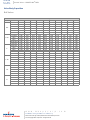
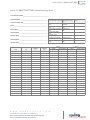
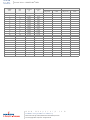
Valve Body Capacities
Ball Valves
Size
0.5”
0.75”
1”
1.25”
1.5”
2”
Insert
1/32” Slot
1/16” Slot
1/8” Slot
30°V
60°V
Round Port
1/16” Slot
1/8” Slot
30°V
60°V
Round Port
1/16” Slot
3/16” Slot
30°V
60°V
90°V
Round Port
3/16” Slot
30°V
60°V
90°V
Round Port
3/16” Slot
30°V
60°V
90°V
Round Port
1/4” Slot
30°V
60°V
90°V
Round Port
0.0%
0.00
0.00
0.00
0.00
0.00
0.00
0.00
0.00
0.00
0.00
0.00
0.00
0.00
0.00
0.00
0.00
0.00
0.00
0.00
0.00
0.00
0.00
0.00
0.00
0.00
0.00
0.00
0.00
0.00
0.00
0.00
0.00
11.1%
0.00
0.01
0.01
0.01
0.01
0.15
0.01
0.01
0.01
0.01
0.21
0.03
0.03
0.03
0.03
0.03
0.58
0.05
0.05
0.06
0.06
0.91
0.05
0.05
0.06
0.06
1.50
0.05
0.05
0.06
0.06
2.20
Flow Coefficient - Cv vs. % open
22.2%*
33.3%
44.4%
55.6%
0.03
0.07
0.12
0.16
0.07
0.20
0.33
0.46
0.10
0.36
0.61
0.86
0.11
0.24
0.36
0.56
0.12
0.33
0.60
0.84
0.29
0.46
0.70
1.10
0.06
0.24
0.40
0.56
0.14
0.39
0.65
0.90
0.11
0.24
0.41
0.67
0.13
0.36
0.55
1.00
0.43
0.70
1.10
1.60
0.10
0.40
0.67
0.94
0.22
0.82
1.40
1.90
0.21
0.56
1.00
1.60
0.30
0.78
1.20
2.30
0.48
1.20
2.30
3.50
1.20
1.90
2.80
4.30
0.38
1.40
2.40
3.40
0.39
1.00
1.80
2.90
0.48
1.30
2.00
3.70
0.78
2.00
3.70
5.70
1.80
3.00
4.40
6.70
0.47
1.80
3.00
4.20
0.41
1.20
2.10
3.50
0.57
1.70
3.00
5.60
1.00
2.80
4.50
8.10
3.00
4.80
7.20
11.00
0.75
2.90
4.80
6.80
0.55
1.70
3.40
5.70
0.70
2.60
4.90
9.30
0.88
3.30
6.10
11.70
4.30
7.00
10.50
16.20
66.7%
0.20
0.60
1.10
0.84
1.40
1.80
0.73
1.20
1.00
1.50
2.60
1.20
2.50
2.40
3.60
5.40
7.00
4.40
4.40
5.80
8.80
10.90
5.40
5.20
9.10
13.40
18.00
8.70
8.30
15.50
19.40
26.40
77.8%
0.24
0.73
1.40
1.10
2.00
2.60
0.90
1.40
1.40
2.30
4.00
1.50
3.10
3.40
5.30
7.70
10.50
5.40
6.40
8.50
12.50
16.40
6.80
7.60
13.20
19.70
27.00
10.80
12.10
22.20
27.50
39.60
*Select valves for minimum controllable Cv at 22°. Errors may become substantial below this point.
w w w . m a x o n c o r p . c o m
combustion systems for industry
Maxon reserves the right to alter specifications and data without prior notice.
© 2014 Copyright Maxon Corporation. All rights reserved.
88.9%
0.28
0.86
1.60
1.60
3.10
4.30
1.00
1.70
1.90
3.60
6.40
1.70
3.50
4.60
8.30
10.80
17.00
6.20
8.60
13.40
17.50
26.60
7.70
10.30
19.80
30.90
44.00
12.30
16.60
32.10
40.10
64.00
100%
0.32
1.00
1.80
2.10
4.40
6.40
1.20
1.90
2.60
5.00
9.60
1.90
4.00
6.20
11.60
12.10
26.00
6.90
11.40
18.70
19.70
40.60
8.60
13.70
28.40
47.10
65.50
13.80
22.20
47.20
59.00
96.00
Control Valves - SMARTLINK® MRV
10-30.7-23
E - i - 3/14
50120624-001/
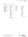
Ball Valves
Additional Ball Valve Options for Special Configuration
Body Connection
Flat-Faced Flanged
Butt Weld
Extended Butt Weld
Clamp Ends
Groove Ends
Socket Weld
Extended Socket Weld
Tube Ends
300# RF Flanged
600# RF Flanged
Body Seals & Packing
Body Seals
Graphite
Kel-F
Peek
RPTFE
Carbon-Filled RPTFE
UHMWPE
Viton
Body Material
Duplex
400 SS
Alloy 20
Monel
Bronze
Hastelloy c
CF8
Titanium
Packing
Graphite
RPTFE
Carbon-Filled RPTFE
Thrust Washer
Graphite
Hostaflon
Kel-F
Peek
RPTFE
Carbon-Filled RPTFE
UHMWPE
w w w . m a x o n c o r p . c o m
combustion systems for industry
Maxon reserves the right to alter specifications and data without prior notice.
© 2014 Copyright Maxon Corporation. All rights reserved.
Body Internals
Stem & Ball
Duplex
400 SS
Alloy 20
Monel
Bronze
Hastelloy c
CF8
Titanium
Seat Rings
PFA
Delrin
Hostaflon
Kel-F
Peek
RPTFE
Carbon-Filled RPTFE
10-30.7-24
E - i - 3/14
Control Valves - SMARTLINK® MRV
50120624-001/
Assembly Specifications
Ball Valves
6
5
4
3
2
1
Item Number
1
2
3
4
5
6
Description
Valve Body Sub-assembly
Bracket
Button Head Screw
Coupling Collar
Coupling
Hard Stop Pin
Component Material Specifications
Based on selection on page 10-30.7-21
6063-T6 Aluminum Alloy UNS A96063
18-8 (type 303) Stainless Steel
Zinc Plated Alloy Steel
303 Stainless Steel ASTM A582 UNS No. S30300
420 Stainless Steel
w w w . m a x o n c o r p . c o m
combustion systems for industry
Maxon reserves the right to alter specifications and data without prior notice.
© 2014 Copyright Maxon Corporation. All rights reserved.
10-30.7-25
E - i - 3/14
Control Valves - SMARTLINK® MRV
50120624-001/
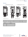
Dimensions
0.5” SMARTLINK® Ball Valve - Threaded
A
E
1
B
0.5” SMARTLINK® Ball Valve - Flanged
A
F
E
1
B
2
F
2
C
C
D
D
3
3
MØ
H
G
NØ
4
I
G
OØ
J
P
Q
K
R
L
Approximate weight: 12 lbs.
Approximate weight: 14 lbs.
Size
A
B
C
D
E
0.5”
4.0
2.0
10.83
9.8
4.38
Number
1
2
3
4
Dimensions in inches unless stated otherwise
H
F
G
I
J
K
L
oct.
1.89
2.0
1.2
1.0
Description
Temporary shipping plug
1/2” NPT threads
Inlet end
1/2” NPT
w w w . m a x o n c o r p . c o m
combustion systems for industry
Maxon reserves the right to alter specifications and data without prior notice.
© 2014 Copyright Maxon Corporation. All rights reserved.
2.0
1.45
2.9
M
Ø
N
Ø
O
Ø
P
Q
R
3.5
2.38
0.62
45°
2.12
4.25
10-30.7-26
E - i - 3/14
Control Valves - SMARTLINK® MRV
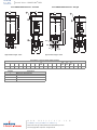
50120624-001/
0.75” SMARTLINK® Ball Valve - Threaded
A
E
1
B
0.75” SMARTLINK® Ball Valve - Flanged
A
F
1
B
2
2
C
C
D
D
3
3
MØ
1.4
G
NØ
4
G
I
J
K
OØ
P
Q
R
L
Approximate weight: 13 lbs.
Approximate weight: 16 lbs.
Size
A
B
C
D
0.75”
4.0
2.0
10.9
9.87
Number
1
2
3
4
Dimensions in inches unless stated otherwise
H
E
F
G
I
J
K
L
oct.
4.38 1.89 2.1
1.4 1.04 2.08 1.6
3.2
M
Ø
3.88
N
O
Ø
Ø
2.75 0.62
Description
Temporary shipping plug
1/2” NPT threads
Inlet end
3/4” NPT
w w w . m a x o n c o r p . c o m
combustion systems for industry
Maxon reserves the right to alter specifications and data without prior notice.
© 2014 Copyright Maxon Corporation. All rights reserved.
P
45°
Q
R
2.31 4.62
Control Valves - SMARTLINK® MRV
10-30.7-27
E - i - 3/14
50120624-001/
1” SMARTLINK® Ball Valve - Threaded
1” SMARTLINK® Ball Valve - Flanged
E
A
1
B
A
F
E
1
B
F
2
2
C
C
D
D
3
3
MØ
G
H
NØ
4
G
I
OØ
J
Q
P
K
R
L
Approximate weight: 15 lbs.
Size
A
B
1”
4.0
2.0
Number
1
2
3
4
Approximate weight: 18 lbs.
Dimensions in inches unless stated otherwise
H
C
D
E
F
G
I
J
K
L
oct.
11.14 10.11 4.38 1.89 2.6
1.7 1.25 2.5 1.95 3.9
Description
Temporary shipping plug
1/2” NPT threads
Inlet end
1/2” NPT
w w w . m a x o n c o r p . c o m
combustion systems for industry
Maxon reserves the right to alter specifications and data without prior notice.
© 2014 Copyright Maxon Corporation. All rights reserved.
M
Ø
4.25
N
Ø
3.12
O
Ø
0.62
P
Q
R
45°
2.5
5.0
10-30.7-28
E - i - 3/14
Control Valves - SMARTLINK® MRV
50120624-001/
1.25” SMARTLINK® Ball Valve - Threaded
A
1.25” SMARTLINK® Ball Valve - Flanged
E
1
B
A
F
E
1
B
F
2
2
C
C
D
D
5
O
H
C
O
C
3
P∅
3
I
G
N
4
O∅
Q∅
J
G
K
R
L
S
T
M
Approximate weight: 16.5 lbs.
Size
A
B
1.25”
4.0
2.0
Number
1
2
3
4
5
C
D
11.06 10.03
Approximate weight: 21.5 lbs.
E
4.38
Dimensions in inches unless stated otherwise
N
F
G
H
I
J
K
L
M
oct.
1.88
2.9
1.91
1.47
1.5
3.0
2.2
4.4
2.1
O
Ø
P
Ø
Q
Ø
R
S
T
3.5
.62
4.62
45°
2.75
5.5
Description
Temporary shipping plug
1/2” NPT threads
Inlet end
1-1/4” NPT
150# ANSI flange
w w w . m a x o n c o r p . c o m
combustion systems for industry
Maxon reserves the right to alter specifications and data without prior notice.
© 2014 Copyright Maxon Corporation. All rights reserved.
10-30.7-29
E - i - 3/14
Control Valves - SMARTLINK® MRV
50120624-001/
1.5” SMARTLINK® Ball Valve - Threaded
A
E
1
B
1.5” SMARTLINK® Ball Valve - Flanged
F
A
E
1
B
F
2
2
C
C
D
D
5
O
O
H
C
C
3
P∅
3
I
G
N
O∅
4
Q∅
J
G
R
K
S
T
L
M
Approximate weight: 19 lbs.
Approximate weight: 26 lbs.
Size
A
B
C
D
E
1.5”
4.0
2.0
11.3
10.27
4.38
Number
1
2
3
4
5
Dimensions in inches unless stated otherwise
N
F
G
H
I
J
K
L
M
oct.
1.88
3.36
1.91
1.71
1.7
3.4
Description
Temporary shipping plug
1/2” NPT threads
Inlet end
1-1/2” NPT
150# ANSI flange
w w w . m a x o n c o r p . c o m
combustion systems for industry
Maxon reserves the right to alter specifications and data without prior notice.
© 2014 Copyright Maxon Corporation. All rights reserved.
2.35
4.7
2.3
O
Ø
P
Ø
Q
Ø
R
S
T
3.88
.62
5.0
45°
3.25
6.5
10-30.7-30
E - i - 3/14
Control Valves - SMARTLINK® MRV
50120624-001/
2” SMARTLINK® Ball Valve - Threaded
A
2” SMARTLINK® Ball Valve - Flanged
E
1
B
A
F
E
1
B
F
2
2
C
C
D
D
5
O
H
C
3
3
I
G
N
Q∅
4
P∅
O∅
J
G
R
S
K
T
L
M
Approximate weight: 22 lbs.
Size
A
B
2”
4.0
2.0
Number
1
2
3
4
5
C
D
11.53 10.49
Approximate weight: 31 lbs.
E
4.38
Dimensions in inches unless stated otherwise
N
F
G
H
I
J
K
L
M
oct.
1.88
3.75
1.91
1.94
1.90
3.80
2.75
5.5
2.8
O
Ø
P
Ø
Q
Ø
R
S
T
4.75
.75
6.0
45°
3.5
7.0
Description
Temporary shipping plug
1/2” NPT threads
Inlet end
2” NPT
150# ANSI flange
w w w . m a x o n c o r p . c o m
combustion systems for industry
Maxon reserves the right to alter specifications and data without prior notice.
© 2014 Copyright Maxon Corporation. All rights reserved.
Control Valves - SMARTLINK® MRV
10-30.7-31
E - i - 3/14
50120624-001/
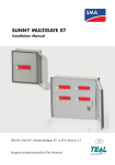
Model Number Description
Control Actuator
The model number shown on the actuator nameplate can accurately identify every MAXON SMARTLINK® MRV Control Actuator.
The example below shows a typical SMARTLINK® MRV Control Actuator model number, along with the available choices for each
item represented in the model number. The first choice determines the actuator's configured item number. The next six choices in
the model number identify the connection and actuator options.
K1
1E
A
Series
SR CA - SMARTLINK® MRV
Control Actuator
Torque Rating
1 - 300 in-lbs
X - Special
Connection
K1 - 1/2" Keyed Output Shaft
L1 - Linkage Arm
S1 - 1/2" Square Output Shaft
S2 - 3/4" Square Output Shaft
Software Version [1]
1E - Standard software
-
0
Valve Number
0 - Valve 0
1 - Valve 1
2 - Valve 2
3 - Valve 3
Rotation
1 - Clockwise
2 - Counter-clockwise
Language
A - English
X - Special
[1] The latest version is the default.
Control Actuator Rotation
1) Clockwise rotation
2) Counter-clockwise
rotation
1
2
w w w . m a x o n c o r p . c o m
combustion systems for industry
Maxon reserves the right to alter specifications and data without prior notice.
© 2014 Copyright Maxon Corporation. All rights reserved.
Rotation
1
-
Valve
Number
Language
-
Software
Version
SR CA
Torque
Rating
Series
Connection
Configured Item Number
-
2
10-30.7-32
E - i - 3/14
Control Valves - SMARTLINK® MRV
50120624-001/
Dimensions
Control Actuator
B
A
M
N
2
3
D
C
E
4
F
G
5
H
O
I
J
1
P
U
K
Q
LØ
R
K
S
J
1/2” Keyed Output
V
W
TØ
Z
AA
1/2” Square Output
X
Y
3/4” Square Output
Approximate weight: 15 lbs
A
4.0
B
2.0
C
10.08
O
1.75
P
3.5
Q
0.25
Number
1
2
3
4
5
D
6.65
Dimensions in inches unless specified otherwise
E
F
G
H
I
J
2.46
0.54
1.29
2.5
5.0
2.0
Dimensions in inches unless specified otherwise
R
S
TØ
U
V
W
X
0.25
0.5
1.0
2.0
1.0
0.375 0.375
K
1.0
LØ
1.0
M
4.38
Y
0.75
Z
1.0
AA
2.0
Description
.5 dia. w/ 1/8” key
Temporary shipping plug
1/2” NPT threads
4 x 4.1
4X 3/8-16 UNC
w w w . m a x o n c o r p . c o m
combustion systems for industry
Maxon reserves the right to alter specifications and data without prior notice.
© 2014 Copyright Maxon Corporation. All rights reserved.
N
1.88
Control Valves - SMARTLINK® MRV
10-30.7-33
E - i - 3/14
50120624-001/
Control Actuator
B
A
N
1
M
2
D
C
E
3
F
G
H
O
P
4
I
I
H
JØ
L
K
Linkage Arm
Approximate weight: 15 lbs
A
4.0
B
2.0
Number
1
2
3
4
C
10.08
D
6.65
E
2.46
Dimensions in inches unless stated otherwise
F
G
H
I
J Ø K rad. L rad.
2.5
5.0
2.0
1.0
0.27 4.358 3.921
Description
Temporary shipping plug
1/2” NPT threads
4X .41
4X 3/8-16 UNC
w w w . m a x o n c o r p . c o m
combustion systems for industry
Maxon reserves the right to alter specifications and data without prior notice.
© 2014 Copyright Maxon Corporation. All rights reserved.
M
4.38
N
1.88
O
1.75
P
3.5
10-30.7-34
E - i - 3/14
Control Valves - SMARTLINK® MRV
50120624-001/
Model Number Description
Spare Actuator
The model number shown on the actuator nameplate can accurately identify every MAXON SMARTLINK® MRV Spare Actuator.
The example below shows a typical SMARTLINK® MRV Spare Actuator model number, along with the available choices for each
item represented in the model number. The first choice determines the actuator's configured item number. The next five choices in
the model number identify the connection and actuator options.
Series
SR SA - SMARTLINK® MRV
Spare Actuator
1E
A
Rotation
1
Valve
Number
Language
-
Software
Version
SR SA
Torque
Rating
Actuator
Series
Configured Item Number
-
4
Torque Rating
1 - 300 in-lbs
X - Special
Language
A - English
X - Special
Software Version [2]
1E - Standard software
Valve Number
4 - Spare Actuator
-
2
Rotation [1]
1 - Clockwise
2 - Counter-clockwise
[1] The correct rotation must be specified.
a. Butterfly Valves are always supplied in a counter-clockwise rotation.
b. Ball Valves are always supplied in a counter-clockwise rotation.
c. Control Actuators are customer-specific and rotation must be obtained from the actuator this spare is intended to replace.
[2] The latest version is the default.
w w w . m a x o n c o r p . c o m
combustion systems for industry
Maxon reserves the right to alter specifications and data without prior notice.
© 2014 Copyright Maxon Corporation. All rights reserved.
Control Valves - SMARTLINK® MRV
10-30.7-35
E - i - 3/14
50120624-001/
Model Number Description
Control Interface
The model number shown on the control interface nameplate can accurately identify every MAXON SMARTLINK® MRV Control
Interface. The example below shows a typical SMARTLINK® MRV Control Interface model number, along with the available
choices for each item represented in the model number. The first four characters determine the Control Interface's configured item
number. The next 11 characters in the model number identify the assembly options.
Configured
Item #
Series
SR CI - SMARTLINK® MRV Control Interface
Software Version [3]
1E - Standard software
Language
A - English
X - Special
Enclosure
0 - None
1 - 24x20x8, NEMA 4/4X, Window
2 - 24x20x8, NEMA 4/4X, SS304 (1.4301),
Window
3 - 24x20x8, NEMA 4/4X, SS316, Window
4 - 20x16x8, NEMA 4/4X, Window
5 - 20x16x8, NEMA 4/4X, SS304 (1.4301),
Window
6 - 20x16x8, NEMA 4/4X, SS316, Window
7 - 20x16x8, NEMA 4/4X, No Window
8 - 20x16x8, NEMA 4/4X, SS304 (1.4301), No
Window
9 - 20x16x8, NEMA 4/4X, SS316, No Window
X - Special
1
-
Valve Count
A
Rail
Assemblies
1
Relay Output
Interface
-
Relay Input
Interface
2
Network
Interface
Enclosure
A
Power
Supply
Language
1E
Interface
Panel/Plate
Software
Version
SR CI
User Display
Series
Assembly Options
1
B
1
1
2
User Display [1]
0 - None
1 - Mounted Inside Enclosure
2 - Mounted Outside Enclosure
3 - Mounted Outside Enclosure w/dust
cover
Interface Panel/Plate
0 - None
A - 24x20 Plate, prewired
B - 24x20 316SS Plate, prewired
C - 20x16 Plate, prewired
D - 20x16 316SS Plate, prewired
X - Special
Power Supply
0 - None
1 - 24VDC
X - Special
* - Included w/Interface Panel
[1] Outside enclosure can only be chosen for a non-window enclosure
[2] One option must be chosen when an Interface Panel/Plate is specified
[3] The latest version is the default.
w w w . m a x o n c o r p . c o m
combustion systems for industry
Maxon reserves the right to alter specifications and data without prior notice.
© 2014 Copyright Maxon Corporation. All rights reserved.
Network Interface
0 - None
1 - Yes
* - Included w/Interface Panel
Relay Input Interface [2]
0 - None
A - 24 VDC
B - 120 VAC
C - 230 VAC
Relay Output Interface
0 - None
1 - Yes
* - Included w/Interface Panel
Rail Assemblies
0 - None
1 - Control Rail Assembly
2 - Control Rail and Terminal Block
Assembly
* - Both included w/Interface Panel
Valve Count
2 - Two Valve System
3 - Three Valve System
4 - Four Valve System
10-30.7-36
E - i - 3/14
Control Valves - SMARTLINK® MRV
50120624-001/
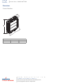
Dimensions
Control Interface
A
B
C
Dimensions in inches unless stated otherwise
A
B
C
1.00
4.57
4.53
w w w . m a x o n c o r p . c o m
combustion systems for industry
Maxon reserves the right to alter specifications and data without prior notice.
© 2014 Copyright Maxon Corporation. All rights reserved.
Control Valves - SMARTLINK® MRV
10-30.7-37
E - i - 3/14
50120624-001/
24 x 20” SMARTLINK® MRV Interface Panel (without enclosure)
A
B
C
1
F
2
G
D
E
3
4
6
5
NOTE: Maximum options shown
A
18.2
B [1]
17.18
Dimensions in inches unless stated otherwise
C
D
E [1]
8.59
22.2
19.7
[1] Mounting centers
Number
1
2
3
4
5
6
Description
1” wide x 2” high wire duct (typ.)
Control rail assembly
Terminal block rail assembly
Warning label
Interface panel label
Ground label
w w w . m a x o n c o r p . c o m
combustion systems for industry
Maxon reserves the right to alter specifications and data without prior notice.
© 2014 Copyright Maxon Corporation. All rights reserved.
F
7.51
G
17.01
10-30.7-38
E - i - 3/14
Control Valves - SMARTLINK® MRV
50120624-001/
20 x 16” SMARTLINK® MRV Interface Panel (without enclosure)
A
B
1
C
G
F
2
D
E
3
4
6
5
NOTE: Maximum options shown
A
14.2
B [1]
13.18
Dimensions in inches unless specified otherwise
C
D
E [1]
6.59
18.2
15.7
F
14.12
[1] Mounting centers
Number
1
2
3
4
5
6
Description
1” wide x 2” high wire duct (typ.)
Control rail assembly
Terminal block rail assembly
Warning label
Interface panel label
Ground label
w w w . m a x o n c o r p . c o m
combustion systems for industry
Maxon reserves the right to alter specifications and data without prior notice.
© 2014 Copyright Maxon Corporation. All rights reserved.
G
5.62
Control Valves - SMARTLINK® MRV
10-30.7-39
E - i - 3/14
50120624-001/
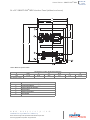
24 x 20” SMARTLINK® MRV Interface Panel (with enclosure)
1
A
B
C
D
F
NOTE: Maximum options shown
A
18.5
Number
1
B
9.25
Dimensions in inches unless stated otherwise
C
D
24.0
25.5
E
27.0
F
1.25
Description
Mounting lug
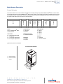
Enclosure options
User display may be door mounted or mounted internally in the panel on a DIN rail. For door mounted selections, a dust cover is
available and recommended for most installations. For internally mounted user displays, a window kit is available for monitoring.
User display may also be mounted remotely from the interface panel to maintain enclosure ratings.
Note: Selection of door mounted components will alter the enclosure rating of panels. NEMA 4X / IP66 ratings cannot be
maintained.
w w w . m a x o n c o r p . c o m
combustion systems for industry
Maxon reserves the right to alter specifications and data without prior notice.
© 2014 Copyright Maxon Corporation. All rights reserved.
E
10-30.7-40
E - i - 3/14
Control Valves - SMARTLINK® MRV
50120624-001/
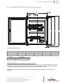
20 x 16” SMARTLINK® MRV Interface Panel (with enclosure)
4
A
5
B
G
6
H
AA
1
E
C
Section AA
Mounting lug detail
D
2
3
F
NOTE: Maximum options shown
A
14.5
Number
1
2
3
4
5
6
B
7.25
Dimensions in inches unless stated otherwise
C
D
E
F
20.0
21.5
23.0
1.25
G
1.5
H
1.5
Description
Logo label
User display (optional, door mounted only)
Dust cover (optional)
Mounting lug
.44 x .75 slot
Alternate position
Enclosure options
User display may be door mounted or mounted internally in the panel on a DIN rail. For door mounted selections, a dust cover is
available and recommended for most installations. For internally mounted user displays, a window kit is available for monitoring.
User display may also be mounted remotely from the interface panel to maintain enclosure ratings.
Note: Selection of door mounted components will alter the enclosure rating of panels. NEMA 4X / IP66 rating cannot be
maintained.
w w w . m a x o n c o r p . c o m
combustion systems for industry
Maxon reserves the right to alter specifications and data without prior notice.
© 2014 Copyright Maxon Corporation. All rights reserved.
Control Valves - SMARTLINK® MRV
10-30.7-41
E - i - 3/14
50120624-001/
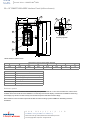
Model Number Description
User Display
The model number shown on the user display nameplate can accurately identify every MAXON SMARTLINK® MRV User Display.
The example below shows a typical SMARTLINK® MRV User Display model number, along with the available choices for each
item represented in the model number. The first choice determines the user display's configured item number. The next two
choices in the model number identify the user display options.
Series
SR UD - SMARTLINK® MRV
User Display
-
Language
SR UD
Software
Version
Options
Series
Configured Item Number
1E
A
Software Version [1]
1E - Standard software
Language
A - English
B - Dutch
C - French
D - German
X - Special
[1] The latest version is the default.
w w w . m a x o n c o r p . c o m
combustion systems for industry
Maxon reserves the right to alter specifications and data without prior notice.
© 2014 Copyright Maxon Corporation. All rights reserved.
10-30.7-42
E - i - 3/14
Control Valves - SMARTLINK® MRV
50120624-001/
Installation and Operating Instructions
Before operating this product, check all specifications (Pages 10-30.7-5 and -6) and safety requirements (Page 10-30.743) to ensure the product is suitable and safe for the intended application. In addition, read all installation, commissioning, and operating instructions. The SMARTLINK® MRV system must be set-up and maintained in the field by qualified
combustion personnel. If the equipment is used in a manner not specified, the protection provided by the equipment
may be impaired.
Installation Instructions:
Safety Requirements..............................................................................................................................................10-30.7-43
SMARTLINK® MRVcomponents ............................................................................................................................10-30.7-44
Optional Components ............................................................................................................................................10-30.7-45
Optional SMARTLINK® MRV Interface Panel Assemblies ......................................................................................10-30.7-45
Mechanical Installation ...........................................................................................................................................10-30.7-46
Electrical Installation ..............................................................................................................................................10-30.7-48
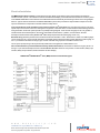
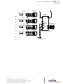
Typical SMARTLINK® MRV wiring schematic.........................................................................................................10-30.7-50
Operating Instructions:
Understanding the SMARTLINK® MRV Control Interface .......................................................................................10-30.7-55
Using the Control Interface for Command Entry......................................................................................................10-30.7-56
User Display Operation & Wiring Checkout ............................................................................................................10-30.7-58
Operational Checkout ............................................................................................................................................10-30.7-59
System Configuration.............................................................................................................................................10-30.7-60
10-Point System Commissioning............................................................................................................................10-30.7-61
19-Point System Commissioning............................................................................................................................10-30.7-61
Custom Startup Positions .......................................................................................................................................10-30.7-61
Commissioning Procedure with Control Interface ...................................................................................................10-30.7-62
Commissioning Procedure with User Display .........................................................................................................10-30.7-63
Unit Locking and Passcode Entry ...........................................................................................................................10-30.7-64
Manual Operation...................................................................................................................................................10-30.7-65
Power Loss with Large Valves (>12”)......................................................................................................................10-30.7-65
Troubleshooting and Alarms / Faults ......................................................................................................................10-30.7-66
Actuator Replacement............................................................................................................................................10-30.7-68
SMARTLINK® MRV Reference Tables:
Table 1: SMARTLINK® MRV Interface Panel Terminal Descriptions.......................................................................10-30.7-69
Table 2: SMARTLINK® MRV Valve Actuator Terminal Descriptions .......................................................................10-30.7-70
Table 3: SMARTLINK® MRV Interface Panel Field Wiring Specifications ...............................................................10-30.7-71
Table 4: SMARTLINK® MRV Control Interface Terminal Descriptions ....................................................................10-30.7-72
Table 5: SMARTLINK® MRV Control Interface Field Wiring Specifications .............................................................10-30.7-73
Table 6: SMARTLINK® MRV Relay Input Interface Terminal Descriptions and Wiring Specifications .................... 10-30.7-74
Table 7: SMARTLINK® MRV Relay Output Interface Terminal Descriptions and Wiring Specifications.................. 10-30.7-75
Table 8: SMARTLINK® MRV Network Interface Terminal Descriptions and Wiring Specifications ......................... 10-30.7-76
Table 9: SMARTLINK® MRV User Display Terminal Descriptions and Wiring Specifications................................. 10-30.7-77
Table 10: SMARTLINK® MRV Relay Output Interface Checkout Procedures .........................................................10-30.7-78
Table 11: SMARTLINK® MRV System Configuration Settings................................................................................10-30.7-79
Table 12: SMARTLINK® MRV User Commands – Command Set A........................................................................10-30.7-80
Table 13: SMARTLINK® MRV User Commands – Command Set B........................................................................10-30.7-82
Table 14: SMARTLINK® MRV User Commands – Command Set C........................................................................10-30.7-84
Table 15: SMARTLINK® MRV User Display Command Summary ..........................................................................10-30.7-85
Table 16: SMARTLINK® MRV Commissioning Sheet .............................................................................................10-30.7-87
w w w . m a x o n c o r p . c o m
combustion systems for industry
Maxon reserves the right to alter specifications and data without prior notice.
© 2014 Copyright Maxon Corporation. All rights reserved.
Control Valves - SMARTLINK® MRV
10-30.7-43
E - i - 3/14
50120624-001/
Installation Instructions
Safety Requirements
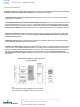
1. The SMARTLINK® MRV system should be used for positioning of multiple valves/dampers to control the air/fuel ratio to industrial/
commercial burners. The product is intended to replace mechanically or pneumatically linked air/fuel ratio control equipment in
combustion applications that can benefit from increased positioning repeatability and tamper resistance. If the equipment is used in a
manner not specified, the protection provided by the equipment may be impaired.
2. This product performs fail-safe air and fuel valve positioning only and does NOT include any air proving, flow monitoring, flame
detection, or burner management functions. This product operates in response to burner management start-up commands (i.e. Purge,
Light-off, Modulate) and to the temperature controller's output (or Firing Rate command) after burner start-up.
3. The SMARTLINK® MRV system is only responsible for proper positioning of valves/dampers attached to its actuators. If burner air/fuel
ratio can be significantly affected by other control motors, fans, variable frequency drives, or large changes in process operating
conditions, it is the commissioning engineer's responsibility to apply external equipment to detect unsafe air/fuel ratio operating
conditions.
4. This product must be set-up and maintained by qualified combustion personnel. Before operating this product, read all installation,
commissioning, and operating instructions (pages 10-30.7-43 through 10-30.7-89). Review all product specifications on pages 1030.7-5 and 10-30.7-6 to ensure the product is suitable for the intended application. During the burner commissioning process, external
equipment (i.e. flow/pressure devices, O2 analyzer, etc.) or a view of the burner flame is required to ensure proper valve position setup.
5. This product must be electrically interfaced to the burner management system's permissive circuit or the automatic burner control's
safety circuit. This important wiring requirement ensures that any failure within the SMARTLINK® MRV system can shut down the
combustion system or disable a start-up sequence by turning off the main gas supply to the burner (i.e. de-energizing fuel shut-off
valves). Specifically, MAXON Relay Output Interface contacts (CE1/CE1R, CE2/CE2R, CO1/CO1R) must be connected in series with
the permissive circuit. If the minimum system is purchased and the Relay Output Interface is not provided, it is the commissioning
engineer's responsibility to connect the MAXON Control Interface relay drive outputs (RO2 and RO5) to appropriate interface relays
for safe shut down.
6. A current loop output signal (OUT+/OUT- of the Control Interface) is provided for optional monitoring of the start-up state, firing rate,
and valve position (during commissioning). This signal is not designed as a fail-safe output and should not be used by external
equipment to shut down the combustion system without the use of the SMARTLINK® MRV discrete permissive outputs (as discussed
in the previous safety requirement).
7. After mechanical replacement and re-calibration of a valve actuator, the previously commissioned valve positions must be re-verified.
8. The SMARTLINK® MRV Relay Output Interface (ROI), Purge Position Proven (PPP) and Light-off Position Proven (LPP) signals
should be connected to the burner management (or automatic burner control) if a purge and light-off command sequence is required.
These output signals are used to confirm the purge and light-off positions. If the optional Relay Output Interface is not purchased,
Control Interface relay drive signals RO3 and RO4 must be properly connected to customer-supplied interface relays.
9. If the power supply is not MAXON-supplied, a SELV (Safety Extra Low Voltage) rated supply with 24VDC output must be provided.
10. If the components of a SMARTLINK® MRV system are ordered separately (i.e. without a factory-wired Interface Panel assembly), the
commissioning engineer must incorporate a switch or circuit breaker that is in close proximity to the SMARTLINK® system. The switch
or breaker must be marked as the disconnection device for the equipment.
11. To avoid unsafe operating conditions or injury to fingers in the valve adapter assembly, turn off power to the system before actuator
replacement or valve body (or damper) servicing is performed. Read and follow all instructions for actuator removal and re-installation
as described on Page 10-30.7-68. After actuator replacement or valve body servicing, the commissioning engineer must verify burner
performance through the entire operating range and re-adjust valve positions (for the replaced actuator) as required. Refer to the
Commissioning Procedures on Pages 10-30.7-61 through -62. After any actuator replacement or valve body servicing, the
commissioning engineer must also confirm that the valve actuator number "selected" for re-adjustment (using the Control Interface or
User Display) is attached to a known valve body or damper. If a User Display is purchased, the fluid type associated with each valve
actuator should be defined as described in step a of the Commissioning Procedure on Page 10-30.7-63 and this will avoid any
confusion on which actuator controls which valve. Actuators purchased as part of a 2, 3 or 4 valve actuator system are numbered
electronically during manufacturing as #0, #1, #2 and #3. A spare actuator is always identified as #4 and is changed to a #0, 1, 2 or 3
during the replacement procedure. A green diagnostic LED in the actuator's wiring compartment and labeled "DIAG" indicates the
valve number by blinking 0 (always ON), 1, 2, 3 or 4 times per second. On the actuator label, the last digit of the model number also
indicates the valve actuator's number (with the exception of the spare actuator).
w w w . m a x o n c o r p . c o m
combustion systems for industry
Maxon reserves the right to alter specifications and data without prior notice.
© 2014 Copyright Maxon Corporation. All rights reserved.
10-30.7-44
E - i - 3/14
Control Valves - SMARTLINK® MRV
50120624-001/
SMARTLINK® MRV Components
As shown below, the minimum SMARTLINK® MRV system requires two Valve Actuators and one (DIN rail-mounted) Control
Interface. A total of four Valve Actuators can by supported by one Control Interface. In addition, several optional DIN rail-mounted
components are available to simplify electrical interfacing and commissioning. These optional components include:
a) Relay Input Interface – Provides the electrical interface between the 6 Control Interface inputs and the customer’s burner
management or flame safety device. This device is available in 120VAC, 230VAC, and 24VDC models.
b) Relay Output Interface – Provides the electrical interface between the 5 Control Interface outputs and the customer’s burner
management or flame safety device.
c) Network Interface – Provides a plug-type terminal connector for all SMARTLINK® MRV field devices.
d) User Display – Provides a 4-line x 20-character LCD display for system commissioning and maintenance.
e) Universal Power Supply – Provides regulated 24VDC power to all SMARTLINK® MRV system components.
These optional components can be ordered individually and wired by the customer. However, two SMARTLINK® MRV Interface
Panel assemblies are available with factory-wired components as follows:
(1) 24” x 20” Interface Panel: Includes factory-wired Input & Output Relay Interfaces, Network Interface, Supply, Control
Interface, User Display, and Terminal Block Assembly
(2) 20” x 16” Interface Panel: Includes factory-wired Input & Output Relay Interfaces, Network Interface, Supply, Control
Interface, and Terminal Block Assembly
The larger, 24” x 20” Interface Panel includes a User Display. Both Interface Panels provide a 4-Amp breaker and power switch as
well as a labeled terminal block for field wiring.
The Interface Panels can be specified with a windowed, NEMA 4X enclosure in painted steel, 304-stainless or 316-stainless.
When provided with a NEMA 4X enclosure, the complete package is Class I, Division 2, and ATEX and IEC Ex approved
and no purging equipment is required.
Because SMARTLINK® Valve Actuators communicate digitally to the Control Interface, an EIA Level 4 Cable with 2 twisted pair
and shield is required for these connections. Required cable may be purchased from MAXON. See the Electrical Installation
section for wiring specifications.
Minimum SMARTLINK® MRV System Requirements
2 Valve Actuators & 1 Control Interface
w w w . m a x o n c o r p . c o m
combustion systems for industry
Maxon reserves the right to alter specifications and data without prior notice.
© 2014 Copyright Maxon Corporation. All rights reserved.
Control Valves - SMARTLINK® MRV
10-30.7-45
E - i - 3/14
50120624-001/
Optional Components
Relay Input Interface
Relay Output Interface
User Display
Network Interface
Universal Supply
Optional SMARTLINK® MRV Interface Panel Assemblies
Interface Panel with Enclosure
(24” x 20” Interface Panel shown; 20” x 16” Interface Panel
does not include User Display)
Interface Panel without Enclosure
(24” x 20” Interface Panel shown; 20” x 16” Interface Panel
does not include User Display)
w w w . m a x o n c o r p . c o m
combustion systems for industry
Maxon reserves the right to alter specifications and data without prior notice.
© 2014 Copyright Maxon Corporation. All rights reserved.
10-30.7-46
E - i - 3/14
Control Valves - SMARTLINK® MRV
50120624-001/
Mechanical Installation
The mechanical installation of the SMARTLINK® MRV system requires the following:
•
SMARTLINK® Valve Actuators:
Install the Valve Actuator assemblies in any orientation within the appropriate air and fuel pipe lines. Observe good piping
practice when installing valves. Do not use valves or actuators to support the weight of pipe.
•
SMARTLINK® MRV Control Interface and DIN rail-mounted options
(When ordered without Interface Panel):
The Control Interface, Relay Input Interface, Relay Output Interface, Network Interface, User Display, and Universal 24VDC
Power Supply can be installed onto a DIN rail in any orientation. When the Control Interface and optional modules are provided
without a MAXON-supplied enclosure, it is the responsibility of the customer to mount these components in an enclosure that
has a rating greater than or equal to IP40 in order to comply with CE safety approvals. To satisfy FM Class I, Division 2, and
ATEX and IEC Ex hazardous area requirements, the enclosure rating must be greater than or equal to NEMA 4.
•
SMARTLINK® MRV Control Interface
(When ordered with Interface Panel and no enclosure):
Refer to panel drawings on following page. All mounting material (bolts, washers, nuts) are included.
The Interface Panel assembly which includes the Control Interface and all rail-mounted options can be mounted in any
orientation. It is the responsibility of the customer to mount this factory-wired panel assembly within an enclosure that has a
rating greater than or equal to IP40 in order to comply with CE safety approvals. To satisfy FM Class I Division 2, and ATEX and
IEC Ex hazardous area requirements, the enclosure rating must be greater than or equal to NEMA 4.
•
SMARTLINK® MRV Control Interface
(When ordered with Interface Panel & Enclosure):
The enclosed Control Interface assembly can be mounted in any orientation. All standard MAXON enclosure options are rated
NEMA 4X and IP66. To maintain the environmental rating of the enclosure, NEMA 4X or IP66 conduit fittings (or glands) should
be installed. Provisions for a minimum of two, 1.5 inch should be made for conduit. The preferred hole location for AC power
(or mains) and all AC input/output wiring is on the bottom left or lower left side of the enclosure. The preferred hole location for
all valve actuator communications cable and low voltage (4-20 mA) control/monitoring signals is on the bottom right or lower
right side of the enclosure.
w w w . m a x o n c o r p . c o m
combustion systems for industry
Maxon reserves the right to alter specifications and data without prior notice.
© 2014 Copyright Maxon Corporation. All rights reserved.
Control Valves - SMARTLINK® MRV
10-30.7-47
E - i - 3/14
50120624-001/
24” x 20” SMARTLINK® MRV Interface Panel
(without enclosure)
20” x 16” SMARTLINK® MRV Interface Panel
(without enclosure)
A
A
B
B
1
C
C
1
G
F
2
G
F
2
D
D
E
E
3
3
4
4
6
6
5
5
24” x 20” SMARTLINK® MRV Interface Panel
(with enclosure)
20” x 16” SMARTLINK® MRV Interface Panel
(with enclosure)
1
A
4
A
B
5
B
G
6
H
AA
1
C
D
E
D
2
3
F
w w w . m a x o n c o r p . c o m
combustion systems for industry
Maxon reserves the right to alter specifications and data without prior notice.
© 2014 Copyright Maxon Corporation. All rights reserved.
E
C
F
10-30.7-48
E - i - 3/14
Control Valves - SMARTLINK® MRV
50120624-001/
Electrical Installation
The SMARTLINK® MRV System block diagram below indicates the sources and destinations of all electrical wiring. If the Control
Interface is ordered with an Interface Panel assembly, the following field wiring is required:
•
120/230 VAC supply and protective earth wiring between the customer’s fused, AC power source and Interface Panel
terminal block (L1, L2, and PE).
•
Low voltage 4-20 mA firing rate command and feedback signal wiring between the user’s process controller and Interface
Panel terminal block (INA+, INA-, OUT+, and OUT-). The shield wire for the firing rate command (INA+ and INA-) should be
grounded immediately as it enters the enclosure that houses the MRV Interface Panel. If the Interface Panel is purchased
with the enclosure option, terminate the shield wire on the corner ground post closest to where the cable enters. The shield
wire for the 4-20 mA firing rate feedback (OUT+, OUT-) should be terminated only at the process or temperature controller end.
•
Input Command Relay wiring between the customer’s burner management or flame safety device and the Interface Panel
terminal block (PPC, LPC, MVC, RRC, and CCOM). The ground reference (CCOM) must be wired for any of the input
command signals to function.
•
Output Relay wiring between the customer’s burner management or flame safety system and the Interface Panel terminal
block (ALM/ALMR, CE2/CE1R, PPP/PPPR, and LPP/LPPR).
•
Communications Network wiring between each SMARTLINK® Valve Actuator (+24, GND, DA, DB, SHD) and the 4-terminal
connectors (F24+, F24-, DA, DB) of the Network Interface. The shield wire of each network cable should be connected to the
actuator “SHD” terminal (keeping the shield length to 1 inch or less). The shield wire should also be tied to ground as it enters
the enclosure of the MRV Interface Panel (keeping the maximum length to 6 inches or less). If the Interface Panel is
purchased with the enclosure option, terminate the shield wire on the corner ground post closest to where the cable enters
the enclosure.
I/O Terminal Blocks
VAC Terminals
AC Power
4-20 mA Terminal Block
To/From User’s
To/From Users’s
Burner Management Process Controller
MAXON SMARTLINK® MICRO-RATIO Valve (MRV)
System Block Diagram
SMARTLINK
Local User
Display
Firing Rate
Firing Rate Feedback
SMARTLINK
Relay Input
Interface
(RI1)
SMARTLINK
Relay Output
Interface
(RO1)
SMARTLINK
Valve Actuator #0
SMARTLINK
MRV
Control
Interface
(CI)
SMARTLINK
Valve Actuator #1
SMARTLINK
Network
Interface
(NI)
SMARTLINK
Valve Actuator #2
SMARTLINK
Valve Actuator #3
SMARTLINK
User Display
Circuit
Breaker
24VDC
Power
Supply
SMARTLINK
Future Field Device
Notes:
1. Non-shaded blocks indicate optional MAXON-supplied equipment
2. Shaded blocks indicate SMARTLINK® MRV required components
w w w . m a x o n c o r p . c o m
combustion systems for industry
Maxon reserves the right to alter specifications and data without prior notice.
© 2014 Copyright Maxon Corporation. All rights reserved.
Control Valves - SMARTLINK® MRV
10-30.7-49
E - i - 3/14
50120624-001/
Electrical Installation
The MRV Interface Panel includes a Universal Power Supply, Relay Input Interface, Relay Output Interface and Network
Interface module. (The 24” x 20” Interface Panel also includes a User Display.) These DIN rail-mounted devices are factory-wired
to the SMARTLINK® MRV Control Interface and a labeled terminal block assembly for field wiring as shown in the wiring diagram
below. A “typical” electrical schematic of a SMARTLINK® MRV system is also provided as a representative example of how the
system is interfaced to a temperature controller and flame safety device.
To ensure the burner can be shut down in the event of a SMARTLINK® MRV failure, the commissioning engineer must verify
specific output connections to the burner management equipment or automatic burner controls. Reference the following electrical
wiring information for fail-safe system operation: a) Example Wiring Diagram: Lines 103 and 104 (page 10-30.7-50), b) Table 1,
Interface Panel Terminal Descriptions: CE1/CE1R, CE2/CE2R and CO1/CO1R, c) Table 4, Control Interface Terminal
Descriptions: RO2 and RO5 and d) SMARTLINK® MRV Safety Requirements #5 and #6 (page 10-30.7-43).
Electrical wiring should be performed in accordance with all local and NEC 1 codes. See Reference Table 1 and Table 2 (pages
10-30.7-69 and 10-30.7-70) for terminal descriptions of the MRV Interface Panel and Valve Actuator. Reference Table 3 (page 1030.7-71) summarizes the maximum length, type, and size of all field wiring required for the MRV Interface Panel.
The AC power (mains) wiring must be permanently installed and not supplied as a detachable line cord.
If the Control Interface is purchased without a factory-wired Interface Panel, see Reference Tables 4 through 9 (10-30.7-72
through -77) for terminal descriptions of the individual SMARTLINK® MRV electronic components: Control Interface, Relay Input
Interface, Relay Output Interface, Network Interface and User Display.
SMARTLINK® MICRO-RATIO® Valve (MRV) Interface Panel Block Diagram
Relay
Command
Terminals
Purge Position
Command
Alarm
Control Enable #1
Lightoff Position
Command
Control Enable #2
Modulate Valves
Command
SMARTLINK
Relay Input
Interface
(RII)
Remote Reset
Command
SMARTLINK
MRV
Control
Interface
(CI)
SMARTLINK
Relay Output
Interface
(ROI)
Custom Application
Command #1
Purge Position
Proven
Lightoff Position
Proven
Relay
Output
(Form A)
Terminals
Custom Output #1
Custom Application
Command #2
SMARTLINK
Network
Interface
(NI)
Command
Common
Network & Power
Connectors for
Actuators and
Displays
(Firing Rate Feedback)
(Reserved for Future Use)
(Firing Rate Command)
SMARTLINK
User Display
4-20 mA Inputs &
Output Terminals
(Not included with
20”x16” MRV
Interface Panel)
Circuit
120/230 VAC Breaker
Neutral
Protective Earth
120/230 VAC Power
Input Terminals
24VDC
Power
Supply
w w w . m a x o n c o r p . c o m
combustion systems for industry
Maxon reserves the right to alter specifications and data without prior notice.
© 2014 Copyright Maxon Corporation. All rights reserved.
10-30.7-50
E - i - 3/14
Control Valves - SMARTLINK® MRV
50120624-001/
Typical SMARTLINK® MRV Wiring Schematic
Line
Voltage
Control Panel
Power
Control Panel
Power On
High Temp Limit
Combustion Air
Pressure Switch
Customer
Interlocks #1
Low Gas
Pressure Switch
High Gas
Pressure Switch
To SMARTLINK MRV
Interface Panel
Customer
Interlocks #2
CE2R
SEE NOTE 9
Remote Burner
Start
Flame Safeguard
CO1
Request
for Heat
CO1R
Lockout
Interlocks
Thermal
Sensor
SEE NOTE 9
Interlocks
Proven
Neutral
To SMARTLINK MRV
Interface Panel
Purging
Main Valve
VCS-1
To SMARTLINK MRV
Interface Panel
Blocking Valve
VCS-1
Purge
Complete
Proof of
Closure
To SMARTLINK MRV
Interface Panel
Temperature
Control Enable
w w w . m a x o n c o r p . c o m
combustion systems for industry
Maxon reserves the right to alter specifications and data without prior notice.
© 2014 Copyright Maxon Corporation. All rights reserved.
Control Valves - SMARTLINK® MRV
10-30.7-51
E - i - 3/14
50120624-001/
Flame safeguard
To SMARTLINK MRV
Interface Panel
Alarm
High Fire
Position
Alarm
Spark Ignition
Transformer
Spark Plug
To SMARTLINK MRV
Interface Panel
Low Fire
Position
Pilot Indicator
Relay
Pilot On
Interrupted
Pilot
Pilot Valve
Flame Detector
Shutter
Flame Detector
Pilot Indicator
Relay
Main Valves
To SMARTLINK MRV
Interface Panel
SL-MRV Alarm
SMARTLINK MRV
User Display
SL-MRV Alarm
Reset
To SMARTLINK MRV
Interface Panel
w w w . m a x o n c o r p . c o m
combustion systems for industry
Maxon reserves the right to alter specifications and data without prior notice.
© 2014 Copyright Maxon Corporation. All rights reserved.
To: SMARTLINK MRV
Network Interface
10-30.7-52
E - i - 3/14
Control Valves - SMARTLINK® MRV
50120624-001/
SMARTLINK® MRV Interface Panel without User Display
Circuit
Breaker
SMARTLINK MRV
Control Interface
4-20 mA Temp
Control Input
Power Supply
See
Note
8
SMARTLINK MRV
Relay Input Interface
SMARTLINK MRV
Network Interface
SMARTLINK MRV
Relay Output Interface
w w w . m a x o n c o r p . c o m
combustion systems for industry
Maxon reserves the right to alter specifications and data without prior notice.
© 2014 Copyright Maxon Corporation. All rights reserved.
Control Valves - SMARTLINK® MRV
10-30.7-53
E - i - 3/14
50120624-001/
See Notes 1, 2
SMARTLINK
Valve 0
To: SMARTLINK MRV
Network Interface
Temperature
Controller
See Notes 1, 2
SMARTLINK
Valve 1
To: SMARTLINK MRV
Network Interface
See Notes 1, 2
SMARTLINK
Valve 2
To: SMARTLINK MRV
Network Interface
See Notes 1, 2
Cold
Jumper
4-20 mA
Output
SMARTLINK
Valve 3
To: SMARTLINK MRV
Network Interface
This device is externally
mounted to the enclosure door.
See Note 4
w w w . m a x o n c o r p . c o m
combustion systems for industry
Maxon reserves the right to alter specifications and data without prior notice.
© 2014 Copyright Maxon Corporation. All rights reserved.
To SMARTLINK MRV
Interface Panel
10-30.7-54
E - i - 3/14
Control Valves - SMARTLINK® MRV
50120624-001/
NOTES:
NOTE 1: Recommended wire color code for SMARTLINK® MRV Control Network
SMARTLINK® MRV Network Cable
Component
Terminal
Designation
MAXON
(not to exceed 100 ft.)
Belden
(not to exceed 300 ft.)
brown
F24+ / +24
white / orange
F24- / GND
orange
blue
DA
white / blue
white
DB
blue
black
NOTE 2: All shields should terminate to GND within 6" of where it enters the cabinet.
NOTE 3: Blue 14AWG MTW/AWM wire is to be used on 4-20 mA signal.
NOTE 4: Type "J" thermocouples are color coded with white as (+) and red as (-). Type "K" thermocouples are color coded with yellow as (+) and
red as (-). Thermocouple wires must be run in separate conduit.
NOTE 5: Installation, operation, and maintenance shall conform with local standards, national and local codes, and authorities having jurisdiction.
NOTE 6: Wire numbers assigned only to SMARTLINK® MRV Interface Panel.
NOTE 7: Symbol Key
Indicates terminals and wiring in SMARTLINK MRV control panel
Indicates component terminals
Indicates SMARTLINK MRV interface panel DIN-rail terminal block
Indicates adjacent SMARTLINK MRV interface panel DIN-rail terminal blocks jumpered together
Indicates external wiring
NOTE 8: The ground reference for all input command signals must be wired by the customer and its termination depends on the relay input
interface purchased (i.e. VAC vs. VDC).
NOTE 9: WARNING: Relay contacts CE1/CE2R (and CO1/CO1R for systems with software version release 1C or later) must be wired in series
with the burner management permissive/interlock circuit to ensure the burner can be shut down in the event of a SMARTLINK® MRV
failure. If the SMARTLINK® MRV system is purchased without a MAXON Relay Output Interface (ROI), the commissioning engineer is
responsible for verifying that appropriate interface relays are wired to the burner management system and Control Interface relay drive
outputs, RO2 (and RO5 for systems with software version release 1C or later).
NOTE 10: This wiring schematic represents electrical connections in a "typical" product application. Please refer to the schematics of the specific
application for troubleshooting.
Maintain the integrity of the MAXON enclosure by using NEMA 4X or IP66 rated dust- and water-tight
electrical connectors. Use cable-sealing grips and strain-relief loops for any cord or cable. Use internal
sealing materials on all conduit connections. Moisture can have a harmful effect on device internals if
permitted to enter through wiring connectors. Ensure that the device connection is not at a low point of the
conduit to avoid condensation run-off into the housing; install a drip loop if necessary. Make sure that the
access cover plate is in place and securely fastened. All cover screws should be tightened using an
alternate cross-corner tightening pattern. Cover screws should be checked periodically to ensure
adequate sealing protection.
w w w . m a x o n c o r p . c o m
combustion systems for industry
Maxon reserves the right to alter specifications and data without prior notice.
© 2014 Copyright Maxon Corporation. All rights reserved.
Control Valves - SMARTLINK® MRV
10-30.7-55
E - i - 3/14
50120624-001/
Operating Instructions
The installer should perform the following steps prior to commissioning the SMARTLINK® MRV system:
· Review SMARTLINK® MRV Control Interface operation and command entry
· Wiring checkout prior to applying power
· Operational checkout after applying power
· System configuration if required by the application
· System commissioning for burner operation
Understanding the SMARTLINK® MRV Control Interface
The lights and switches of the SMARTLINK® MRV Control Interface allow the user to:
a) Display and change configuration parameters (i.e. loss of signal position and valve movement),
b) Display the operating mode of the valve and indicate alarm conditions,
c) “Lock” the device electronically to prevent tampering,
d) Customize the position profile of each valve for burner tuning, and
e) Locally control the movement of the valves.
MAN Light - Unit in Manual Positioning Mode when lit or blinking
RUN Light - Unit in Run Mode when lit; Startup Mode when blinking; Position Setup Mode if
RUN and MAN lights are blinking; Shutdown Mode if RUN and MAN lights are OFF.
ALM Light - Alarm exists when lit; Unit is locked if blinking.
0 -9 Lights - Indicates valve position index when unit is in Manual or Position Setup Mode;
Also indicates command number selected by rotary CMD SEL switch and configuration
setting.
ENTER Switch - Momentary pushbutton for command entry and saving configuration or
valve position changes.
MODE Switch - 3 positions: (1) RUN (down) places unit in Run or Startup Mode for relay
input and 4-20mA command operation, (2) Command Entry (middle) for selecting user
command with rotary switch, and (3) CMD abc (up, with momentary action) for Command
Set selection.
ADJUST Switch - 3 positions: (1) MINIMUM (down) for emergency movement to minimum
positions when not in Run Mode, (2) ADJ (middle) enables valve movement in 0.1 degree
steps when using the INC/DEC switch in Manual or Position Setup Mode, and (3) INDEX
enables positioning moves to the 19 position indexes when using INC/DEC switch in Manual
Mode.
INC/DEC Switch - 3 positions: INC and DEC (up & down, with momentary action) for valve
opening and closing in Manual or Position Setup Mode; also used for changing configuration
settings and selecting a valve to change its respective profile. Middle position has no
function.
Command Set Lights - Identifies which command set (a, b, or c) is currently selected (when
blinking) or active (when not blinking).
CMD SEL (Rotary) Switch - Selects command number, 0 through 7
w w w . m a x o n c o r p . c o m
combustion systems for industry
Maxon reserves the right to alter specifications and data without prior notice.
© 2014 Copyright Maxon Corporation. All rights reserved.
10-30.7-56
E - i - 3/14
Control Valves - SMARTLINK® MRV
50120624-001/
Using the Control Interface for Command Entry
There are 3 SMARTLINK® MRV command sets (a, b, and c) as listed below. Several of the commands have special requirements
before they can be executed. For example, before entering the Set Max Position & Ramp Command, the unit must be at position
index #9 or the command cannot be executed.
Command Set "A"
A-0........Enter Manual Positioning Mode ..................Unit not in Shutdown Mode
A-1........Display Alarm Codes
A-2........Enter Position Setup Mode .........................Unit not in Shutdown Mode
A-3........Display/Change Selected Valve
A-4........Commission Valve......................................Unit in Setup Mode, MVC input on;
Shutdown Mode to replace valve
A-5........Set Max Position and Ramp........................Unit at Position Index = 9, not in
Shutdown Mode
A-6........Set Min Position and Ramp.........................Unit at Position Index = 0, not in
Shutdown Mode
A-7........Unlock System Configuration .....................Unit must be already "locked"
Command Set "B"
B-0........Select Loss of Signal Position
B-1........Set Purge Position ......................................Custom Startup enabled,
MVC off, not in Shutdown Mode
B-2........Set Standby Position ..................................Custom Startup enabled,
MVC off, not in Shutdown Mode
B-3........Select Deadband
B-4........Select Startup Configuration
B-5........Set Light-Off Position..................................Custom Startup enabled,
MVC off, not in Shutdown Mode
B-6........Select Auto Ramp Adjust
B-7........Select Movement Configuration
Command Set "C"
C-0........Valve Test...................................................Unit in Shutdown Mode
C-1........Reserved for Trained Personnel .................See Installation & Operating Instructions
C-2........Reserved for Trained Personnel .................See Installation & Operating Instructions
C-3........Reset Factory Default Settings ...................Unit in Position Setup Mode, MVC input off
C-4........Enter New Lock Passcode ..........................Unit "unlocked" and lock function enabled to
modify
C-5........Select Lock Enable / Disable.......................Unit "unlocked" to modify
C-6........Save Profile as Backup ..............................Unit in Position Setup Mode
C-7........Restore Backup Profile ..............................Unit in Position Setup Mode, MVC input off
w w w . m a x o n c o r p . c o m
combustion systems for industry
Maxon reserves the right to alter specifications and data without prior notice.
© 2014 Copyright Maxon Corporation. All rights reserved.
Control Valves - SMARTLINK® MRV
10-30.7-57
E - i - 3/14
50120624-001/
Each of the user commands can be initiated by following the general command entry procedure outlined below.
General Command Entry Instructions:
1. A user command can be performed only when the following conditions are all satisfied:
a.) Mode switch is not in the RUN position,
b.) One of the green Command Set lights (a, b, c) is blinking,
c.) ADJUST switch is not in the MINIMUM position,
d.) Unit is “unlocked”, and
e.) For some commands, the unit must be in a specific mode, position index, etc. (See command entry requirements listed on
page 10-30.7-56 or in Reference Tables 12 through 14 on pages 10-30.7-80 through -84.)
Note: Condition d. above is not required for Command A-7, Unlock Configuration and Command A-1, Display Alarm Codes.
2. If the a, b, or c Command Set light is not blinking, momentarily push the MODE switch in the CMD abc position (up) or, change
the position of the rotary CMD SEL switch. This will start the Command Set light blinking and permit a command to be
entered.
3. Select the desired Command Set by momentarily pushing the MODE switch upward to the CMD abc position. Subsequent
CMD abc switch entries will change the command set selection as indicated by the green Command Set (a, b, c) lights.
4. Select the desired command number by changing the position of the rotary CMD SEL switch. When one of the command set
lights is blinking, the command number selected is indicated by the corresponding numbered (0-9) light being lit.
5. After the command set and number are selected, press the ENTER button. If all of the numbered lights flash momentarily
after the ENTER button is pushed, a command entry error has occurred and the command was not executed. If an entry error
occurs, check to see if the unit is locked (i.e. alarm light blinking) or the ADJUST switch is in the MINIMUM position. If neither
condition exists, check the specific entry requirements of the command.
w w w . m a x o n c o r p . c o m
combustion systems for industry
Maxon reserves the right to alter specifications and data without prior notice.
© 2014 Copyright Maxon Corporation. All rights reserved.
10-30.7-58
E - i - 3/14
Control Valves - SMARTLINK® MRV
50120624-001/
User Display Operation
The optional SMARTLINK® MRV User Display simplifies commissioning and viewing system status with a back-lit, 4-line by 20character, liquid crystal display (LCD). The User Display can be remotely mounted up to 1000 feet away from the Control Interface
for remote commissioning and control room monitoring. Multiple displays can be connected to the system for both local and
remote operation. All commissioning functions provided within the Control Interface can be performed with the User Display.
However, the User Display provides the following functions in addition to the Control Interface commissioning and status
capabilities:
•
•
•
•
•
Alarm and fault condition text message display
Time-stamped history of 6 shutdown events
System and valve maintenance functions
Storing and viewing of up to 5 system profiles
Restoring system profile in replacement Control Interface
See Reference Table 15 for a summary of the Main Menu and Sub-Menu Command list. The five keys on the display are used as
follows:
1)
2)
3)
4)
5)
6)
7)
Press [MENU] key to move down Main Menu or Sub-Menu command list.
Press [BACK] key to move up Main Menu or Sub-Menu list.
Press [ENTER] to move from Main Menu command item to Sub-Menu list.
Press [BACK] key to move from the top command item in a Sub-Menu list back to the Main Menu.
Press [ENTER], [BACK] or [ARROW] keys to accomplish specific Sub-Menu tasks as prompted by the display.
When on a Main Menu item, press [MENU] and [DOWN] keys simultaneously to reach last Main Menu item.
When on a Main Menu item, press [BACK] and [UP] keys simultaneously to reach first main menu item.
Wiring Checkout
Before applying power to the SMARTLINK® MRV Interface Panel, Control Interface, or Valve Actuators, perform the following
wiring checkout:
1) Verify that 120 VAC (or 230 VAC) power and burner management control signals are connected to the proper field wiring
terminals of the SMARTLINK® MRV Interface Panel.
2) If a factory-wired MAXON SMARTLINK® MRV Interface Panel was not purchased, verify that no 120 VAC (or 230 VAC) wiring
is connected directly to any Control Interface or Valve Actuator terminal. The MRV Control Interface (and Valve Actuators)
must be powered by a 24 volt DC source.
3) Verify the proper wire type and maximum wire length requirements are satisfied for all connections.
4) Verify network/power connection color codes are correct for the Valve Actuators.
5) Measure the resistance between earth ground at the enclosure of the Control Interface and each of the four signals wired to the
Valve Actuator: F24+ (Field 24VDC), F24- (Field 24VDC Common), DA (Data-A), and DB (Data-B). The resistance should
indicate an open circuit (i.e., a resistance value greater than 10 Ohms). If an open circuit is not measured, damage or incorrect
wiring of the control network cable exists and must be located.
6) Verify proper termination of shields for the 4-20 mA cables and the power/network cable between the SMARTLINK® MRV
Interface Panel, Control Interface and Valve Actuators.
7) If a MAXON SMARTLINK® MRV Interface Panel is not provided, verify that all customer-provided output relays connected to
RO1 through RO5 of the Control Interface have a 24 VDC coil rating and require less than 100 mA to turn on.
Refer to SMARTLINK® MRV Reference Tables 1 through 5 (pages 10-30.7-69 to -73) for all terminal definitions and wiring/
shielding requirements.
w w w . m a x o n c o r p . c o m
combustion systems for industry
Maxon reserves the right to alter specifications and data without prior notice.
© 2014 Copyright Maxon Corporation. All rights reserved.
Control Valves - SMARTLINK® MRV
10-30.7-59
E - i - 3/14
50120624-001/
Operational Checkout
Apply power to the SMARTLINK® MRV System. If a SMARTLINK® MRV Interface Panel was purchased, switch the breaker
located on the lower rail of the Interface Panel to the ON (or up) position. The breaker switch will power all system components
including the SMARTLINK® Valve Actuators. Perform the following operational checkout prior to attempting burner light-off and
commissioning the system for burner operation:
1) Disable the burner system by turning the combustion blower off and manually turning off the pilot and main fuel supply.
2) Place the Mode switch of the Control Interface in its middle position. With all Valve Actuators wired, verify the Control Interface
Alarm light is off and the Run light is blinking indicating the system is in the Startup Mode. If the Control Interface alarm light is
on, see page 10-30.7-66 on troubleshooting and alarms, to determine the cause of the alarm and corrective actions.
3) Verify operation of each SMARTLINK® MRV relay output by using the procedures summarized in Table 10 (page 10-30.7-78).
If a MAXON MRV Interface Panel is provided, the Relay Output Interface (ROI) is factory-wired to the Control Interface and a
field wiring terminal block for easy access to the output contacts. The relay output terminals of the Control Interface are also
referenced in Table 10 to assist in operational checkout of systems with customer-supplied relays or a PLC-based burner
management system that controls burner startup (without the MAXON Relay Output Interface).
4) Turn on the combustion blower. Re-enable the burner management system but keep the pilot and main fuel supply turned off.
Verify that all combustion system safety interlocks are satisfied.
5) Power cycle SMARTLINK® MRV and verify the relay input commands from the burner management system properly drive
SMARTLINK® MRV to its purge and light-off states. If a MAXON SMARTLINK® MRV Interface Panel is provided, the Relay
Input Interface (RII) is factory-wired to the Control Interface and a field wiring terminal block. The lights of the Relay Input
Interface indicate when each input command relay is energized and the 4-20 mA output (OUT-/OUT+ terminals) can be
measured by a current meter to verify SMARTLINK® MRV has responded to the input command. When the burner
management system (or flame safety) issues a Purge Position Command, the PPC terminal of the Interface Panel is energized
and the Relay Input Interface (terminal #6) outputs a voltage greater than 22 VDC to the Control Interface input terminal RI1
(Relay Input #1). When a Light-Off Position Command is issued, the LPC terminal of the Interface Panel is energized and the
Relay Input Interface (terminal #5) outputs a voltage greater than 5 VDC to the Control Interface input terminal RI2 (Relay Input
#2). The following 4-20 mA output currents can be measured for each of the following SMARTLINK® MRV states: 1 mA=
Standby Positions; 2 mA = Purge Positions; 3 mA = Light-Off Positions.
w w w . m a x o n c o r p . c o m
combustion systems for industry
Maxon reserves the right to alter specifications and data without prior notice.
© 2014 Copyright Maxon Corporation. All rights reserved.
10-30.7-60
E - i - 3/14
Control Valves - SMARTLINK® MRV
50120624-001/
System Configuration
There are 7 SMARTLINK® configuration settings that can be changed through execution of the commands listed below. Detailed
explanations of each setting appear in Reference Table 11: SMARTLINK® MRV System Configuration Summary (page 10-30.779).
Command Name
Select Loss of Signal (LOS) Position
Select Control Deadband
Select Startup Configuration
Select Auto Ramp Adjust
Select Movement Configuration
Enter New Lock Passcode
Select Lock Enable/Disable
Command Number
B-0
B-3
B-4
B-6
B-7
C-4
C-5
Factory Default
Setting #0: Position Index 0 (Minimum)
Setting #2: 0.06% Deadband
Setting #0: Default Startup
Setting #1: Auto Ramp ON
Setting #1: Medium Speed (~40 seconds)
Default Passcode: 0, 0, 0, 0
Setting # 0: Lock Disable
Review the factory default settings before changing any of the system configuration settings. In many applications, modification of
the default settings is not necessary. If a setting does need to be changed, follow the procedure below.
Procedure for Changing a System Configuration Setting:
a) Select and enter the required system configuration command.
b) After the command is entered, one of the numbered (0-9) lights will be on, indicating the current configuration setting. (For
example: If the lock configuration is set to #0, Lock Disable, the 0 light will be solidly lit after Command C-5, Lock Enable/
Disable, is entered successfully.)
c) Select the desired configuration setting by using the INC/DEC switch. As the INC/DEC switch is momentarily pushed up or
down, the selected setting changes as indicated by turning on the corresponding numbered (0-9) light.
d) Push the ENTER button after the desired configuration setting is selected. The numbered light (i.e. selected configuration)
that is lit will momentarily turn off indicating the command is complete and the configuration setting is saved.
e) To confirm the correct setting is saved, re-enter the command and verify the new setting by the numbered (0-9) light indication.
w w w . m a x o n c o r p . c o m
combustion systems for industry
Maxon reserves the right to alter specifications and data without prior notice.
© 2014 Copyright Maxon Corporation. All rights reserved.
Control Valves - SMARTLINK® MRV
10-30.7-61
E - i - 3/14
50120624-001/
10-Point System Commissioning
The SMARTLINK® MRV Control Interface is shipped with configuration settings that support a 10-point commissioning procedure
as described on the following page. Specifically, the Auto Ramp ON configuration is selected as the default setting so that fuel
valve adjustment is needed for only 10 position indexes (0, 1, 2…9). The 9 intermediate position indexes (0.5, 1.5, 2.5, etc.) are
automatically set to positions mid-way between the 10 integer position indexes, 0 through 9. In addition, the Default Startup
Configuration sets the standby, purge, and light-off positions to the same values as those established for Index 0 (minimum), Index
9 (maximum), and Index 0 (minimum), respectively. See Reference Table 11 for a detailed description of these configuration
settings.
When SMARTLINK® MRV is in the Position Setup Mode for commissioning, the ADJUST switch can be pushed to the MINIMUM
position (down). This action will immediately move the valves synchronously to position index #0, the minimum position. This
feature provides a method (during commissioning when the user’s temperature controller is not in automatic mode) to quickly ramp
the burner back to low fire if a process or combustion condition warrants an immediate burner firing rate change.
An optional User Display with a 4-line by 20 character LCD can also be used for SMARTLINK® MRV commissioning instead of
the Control Interface switches and lights. The commissioning procedure using the User Display is described on page 10-30.7-63.
See Reference Table 15 on page 10-30.7-85 for a description of User Display key operation and commands, as well as a
numbered menu structure.
19-Point System Commissioning
There are combustion applications that require burner adjustment at more than 10 points throughout the firing range to meet
emissions or fuel efficiency requirements. For these applications, the Auto Ramp configuration should be OFF, setting #0. With
Auto Ramp OFF, adjustment of each fuel valve at all 19 position indexes (0, 0.5, 1.0, 1.5…8.5, and 9) is now required and no
automatic “smoothing” is performed on points adjacent to the position index being adjusted. The procedure for adjusting all 19
points is identical to the 10-point procedure described above with the following exceptions:
1.) In step g of the 10-Point Commissioning (using the Control Interface) procedure on page 10-30.7-62, execute Command B-6 to
ensure the auto ramp function is OFF, setting #0. In step g of the 10-Point Commissioning (using the User Display), go to Main
Menu 9 (Set Configuration) and use the ARROW up key until the auto ramp configuration can be verified.
2.) In step h, the firing rate should be adjusted at 0.5-position index steps instead of every whole integer position index.
In some applications, it may also be desirable to adjust positions at all 19 points of the air valve(s) in order to provide a linear flow
characteristic. The same 19-point adjustment process used for the fuel valves would be performed for the air valve(s) instead of
the 2-point linear position setup using Commands A-5 and A-6 (described in steps c through e).
Custom Start-up Positions
The Custom Startup Configuration is intended for burners or applications that require standby, light-off, or purge positions that are
independent of the burner’s normal operating valve position curves.
To enable this function using the Control Interface, execute Command B-4, Select Startup Configuration. Use the INC/DEC
switch to select setting #1 (Custom Startup) and press the ENTER switch to save the configuration setting if it has been changed.
Command B-1 (Set Purge Positions), Command B-2 (Set Standby Positions), and Command B-5 (Set Light-Off Positions) can now
be executed to set custom valve positions during startup. See Reference Table 13 for a more detailed explanation of how to use
these commands.
These custom startup adjustment commands can also be executed from the User Display using Main Menu 9 to select the
Startup Configuration item (using the ARROW keys) and Sub-Menu 9.1 to change (ARROW keys) and save (ENTER key) the
setting. See Reference Table 15 (page 10-30.7-85) for the User Display command menu structure.
w w w . m a x o n c o r p . c o m
combustion systems for industry
Maxon reserves the right to alter specifications and data without prior notice.
© 2014 Copyright Maxon Corporation. All rights reserved.
10-30.7-62
E - i - 3/14
Control Valves - SMARTLINK® MRV
50120624-001/
Commissioning Procedure with Control Interface
a)
b)
c)
d)
e)
f)
g)
h)
i)
j)
SMARTLINK® MRV 10-Point Commissioning Procedure with Control Interface
Disable burner light-off by turning off the burner management system or disabling a combustion permissive so that interlocks
cannot be proven. Turn on the combustion blower.
Execute Command A-0, Enter Manual Mode. With the ADJUST switch in the up (INDEX) position, push the INC/DEC switch
momentarily to advance the firing rate to position index #9.
Execute Command A-3 and select the SMARTLINK® Air Valve Actuator’s number by using the INC/DEC switch to light the
desired valve number. (The number of the Air Valve Actuator is on the unit’s label.) Execute Command A-5, Set Max Position & Ramp, and adjust the air valve maximum position to satisfy the pressure/flow requirements of the burner. When this
command is executed, both the yellow and green run lights will be flashing indicating the system is in Position Setup Mode.
With the ADJUST switch in the middle (ADJ) position, push the INC/DEC switch up or down to change the valve position.
Each push of the INC/DEC switch moves the valve 0.1 degrees. If the switch is held in the up or down position for more than
3 seconds, the valve will move in 0.5 degree steps up to a total travel of 8 degrees from the stored valve position. (All the
numbered lights will momentarily flash when this 8 degree limit or the maximum valve travel is reached.) After moving the
valve to the desired position, press the ENTER button to save the position setting. The command ‘a’ light will momentarily
turn off and then back on (solid) after the position is saved. (Any numbered light that was blinking will also momentarily turn
off and then resume blinking after the position is saved.) Record the valve position feedback in milliamps (mA) or percent
that is present on the OUT+/- terminals of the Control Interface.
Execute Command A-0, Enter Manual Mode, again and move to position index #0. Execute Command A-6, Set Min Position
& Ramp, and adjust the minimum air valve position in the same manner as the maximum position was adjusted in step d.
Repeat steps b through e for all other air valves installed. SMARTLINK® MRV is shipped with factory default minimum and
maximum valve positions of 6.0 and 60.0 degrees, respectively.
Momentarily set the mode switch in the RUN position, re-enable the burner management system and light the burner. Execute Command B-6 to ensure the auto ramp function is set to #1, ON. Select the fuel valve for adjustment using Command
A-3 and then execute Command A-6, Set Min Position and Ramp. This command permits adjustment of the minimum position and then creates a linear ramp to the current maximum position. The system is placed in Position Setup Mode, indicated
by the flashing of both the yellow (MANUAL) and green (RUN) lights. With the ADJUST switch in the middle position, trim the
fuel valve's position at index #0 (minimum) based on burner pressure or flow measurement equipment as performed in step
d above. Repeat this step to adjust the minimum and linear position ramp for all other fuel valves in the system.
After adjusting index #0 (and forcing a linear position ramp) for the fuel valve, place the adjust switch in the INDEX (up) position and execute Command A-2 (Enter Position Setup Mode). Move the MRV firing rate to the next whole integer position
index (index #1) by momentarily pressing the INC/DEC switch until the desired index number is turned ON. Move the
ADJUST switch back to the middle (ADJ) position. Use the INC/DEC switch to adjust valve position based on burner pressure or flow measurement and press ENTER to save the profile to memory as described in step d above. Repeat this adjustment procedure for each whole integer index up to and including index #9 (maximum). If necessary, make gas pressure
regulator adjustments at index #9 and then work back down through the lower indexes making adjustments as required.
After the last adjustment is made in Position Setup Mode, use the INC/DEC switch to move to position index #9 (or the highest position index adjusted for all valves) with the ADJUST switch in the INDEX (up) position. Select the air valve using Command A-3 and then execute Command A-4, Commission Valve. Repeat this step for each installed SMARTLINK® MRV valve
actuator. The commission command stores the selected valves current position index as its maximum allowable position
index while in RUN mode (i.e. under 4-20 mA firing rate control). If one valve has a "maximum run index" less than the other
commissioned valves, the system will not modulate above the lowest run index. The system will also not modulate in RUN
mode if any valve is not commissioned.
Record in the SMARTLINK® MRV commissioning table (Table 16, page 10-30.7-87 and -88) the position of each valve and
pressure (or flow) at each index. Execute Command C-6 to save the profile as a backup. Move the MODE switch to the
RUN position and set the user’s temperature controller to AUTO.
w w w . m a x o n c o r p . c o m
combustion systems for industry
Maxon reserves the right to alter specifications and data without prior notice.
© 2014 Copyright Maxon Corporation. All rights reserved.
Control Valves - SMARTLINK® MRV
10-30.7-63
E - i - 3/14
50120624-001/
Commissioning Procedure with User Display
SMARTLINK® MRV 10-Point Commissioning Procedure with User Display
Menu & Sub-Menu reference numbers and instructions for moving between menu levels are shown in Table 15 (page 10-30.7-85)
a) Disable burner pilot trials by turning off the burner management system or disabling a combustion permissive so that interlocks cannot be
proven. Turn on the combustion blower. Go to Sub-Menu 5.5 (Set Valve #) and Sub-Menu 5.6 (Set Fluid) and, using the ARROW keys,
select each valve and its fluid type (air, oxygen, natural gas, propane, etc.). Display of the fluid type during commissioning helps prevent
selection and adjustment of the wrong valve.
b) Go to Menu 2 and enter Manual Mode (Command A-0) by pressing the ENTER key. After entering Manual Mode, Sub-Menu 2.1 (Maximum
Fire) is displayed. Press the ENTER key and wait for the system to move to position index #9. Press the BACK key to return to Main Menu
2. Press the MENU key to move to Main Menu 3 (Set Max & Ramp).
c) If the system is at position index #9 (maximum), press the ENTER key in Menu 3 (Set Max & Ramp, Command A-3). This command permits
adjustment of the maximum position and provides a linear position ramp on all lower indexes. When this command is successfully executed,
both the yellow and green mode lights on the Control Interface will be flashing (indicating that the system is in Position Setup Mode) and
Sub-Menu 3.1 (Set Valve #) is displayed.
d) Use the ARROW keys to select the air valve in Sub-Menu 3.1 (Set Valve #). Press the MENU key to go to Sub-Menu 3.2 (Trim 1.0 deg). Use
the ARROW keys to adjust the air valve's maximum position in 1.0 degree increments until the required burner pressure (flow) is achieved.
The valve's position can be moved 8 degrees from its stored position or until the maximum travel of the valve (80 degrees) is reached. (The
display will indicate an invalid command request if the 8 degree limit or max/min travel is reached.) Press the ENTER key to save the maximum position and linear ramp.
e) Use the BACK key to return to Menu 2 (Manual Mode). Press the ENTER key in Menu 2 to enter Manual Mode (Command A-0). Go to SubMenu 2.4 (Set Valve #) and verify the correct valve is selected. Go back to Sub-Menu 2.2 (Minimum Fire). Press the ENTER key and wait for
the system to move to position index #0 (minimum). When the system is at index #0, go to Main Menu 4 (Set Min & Ramp). Press the
ENTER key and verify the correct valve is selected in Sub-Menu 4.1 (Set Valve #). Go to Sub-Menu 4.2 (Trim 1.0 deg) and use the ARROW
keys to adjust the minimum air valve position in the same manner as the maximum position was adjusted in step d. After adjustment is complete, press ENTER in Sub-Menu 4.2 to save the setting in memory.
Repeat steps b through e for all other air valves installed. SMARTLINK® MRV is shipped with factory default minimum and maximum valve
positions of 6.0 and 60.0 degrees, respectively.
g) Momentarily set the mode switch in the RUN position, re-enable the burner management system and light the burner. Go to Main Menu 9
(Set Configuration) and press the up ARROW key until the Auto Ramp setting is displayed. Auto Ramp should be set to #1, ON. (If not,
press ENTER to change the setting in Sub-Menu 9.1 using the up ARROW key to select ON and press ENTER to save the modified configuration.) Use the BACK key to return to Menu 2 (Manual Mode) and press ENTER. Press MENU to get to Sub-Menu 2.2 (Minimum Fire).
Press ENTER and wait for all valves to get to position index #0 (minimum).Go back to Main Menu 2. Then go to Menu 4 (Set Min & Ramp)
and press ENTER. Go to Sub-Menu 4.1 (Set Valve #) and select the fuel valve using the ARROW keys. Go to Sub-Menu 4.2 (Trim 1.0 deg)
and use the ARROW keys to adjust the minimum fuel valve position for the required burner pressure (flow). After adjustment is complete,
press ENTER to save the setting in memory. Repeat setting the minimum position (and linear ramp) for each fuel valve in the system.
h) Once the fuel valve minimum and linear ramp are set, go to Main Menu 5 (Setup Mode). Press the ENTER key and Sub-Menu 5.1 (Set
Index) is displayed. Use the ARROW keys in Sub-Menu 5.1 to move the system to the next whole integer position index. Press the MENU
key to display Sub-Menu 5.2 (Set Valve #). Verify the correct fuel valve is selected; use the ARROW keys if a change is required. Press the
MENU key to display Sub-Menu 5.3 (Trim 1.0 deg) and then adjust the fuel valve position using the ARROW keys to achieve the required
burner pressure (flow). Press the ENTER key to save the position profile in memory. (Use Sub-Menu 5.4, Trim 0.1 deg, if finer adjustments
are needed.) Select each fuel valve in the system and adjust its position. Repeat this step until all 10 whole integer position indexes are
adjusted. If additional gas pressure is required at index #9 (maximum), adjust the regulator and then re-adjust the fuel valves at each whole
integer index position while working back to index #0 (minimum).
i) After the last adjustment is made in Position Setup Mode, go to Sub-Menu 5.1 (Set Index) and use the ARROW keys to move the system to
index #9 (or the highest possible with the burner firing). Go to Sub-Menu 5.7 (Commission) and press the ENTER key to execute the Commission Valve Command (A-4) for the selected valve. Use the ARROW keys to select each valve and then press ENTER to commission the
f)
j)
newly-selected valve. Repeat this process for each installed SMARTLINK® MRV Valve. The commission command stores the selected
valve's current position index as its maximum allowable position index while in RUN mode (i.e. under 4-20 mA firing rate control). If one
valve has a maximum run index less than the other commissioned valves, the system will not modulate above the lowest run index. The system will also not modulate in RUN mode if any valve is not commissioned.
To make a back-up profile in the Control Interface, go to Sub-Menu 5.9 (Save Back-up) and press ENTER to execute Command C-6, Save
Profile as Back-up. To back-up the profile and all system configuration settings in the User Display, go to Sub-Menu 10.4 (Save System
Data) and press ENTER. Backing up system data to the User Display takes approximately 30 seconds. Go to Sub-Menu 5.8 (Run Mode)
and press ENTER. Place the user's temperature controller in AUTO. SMARTLINK® MRV will modulate the burner's firing rate based on the
4-20 mA input command.
w w w . m a x o n c o r p . c o m
combustion systems for industry
Maxon reserves the right to alter specifications and data without prior notice.
© 2014 Copyright Maxon Corporation. All rights reserved.
10-30.7-64
E - i - 3/14
Control Valves - SMARTLINK® MRV
50120624-001/
Unit Locking and Passcode Entry
The SMARTLINK® MRV Control Interface is shipped with the lock function disabled and a factory default 4-digit passcode or
“combination” of 0,0,0,0. To lock the unit for the first time and change the default passcode, the lock function must first be enabled
(Command C-5) and the default passcode entered (Command A-7) as described in the first two procedures below. After the lock
function is enabled and the unit is “unlocked”, a new passcode can be entered using Command C-4 as described in the procedure
below. If you forget the passcode, call MAXON for the “master” passcode.
Procedure for Enabling the “Lock” Configuration Setting (Command C-5):
a) If the alarm light is blinking, the lock function is already enabled and the unit is in a “locked” state. Before changing the passcode, the unit must be unlocked by entering the current passcode (Command A-7) using the procedure below.
b) If the alarm light is not blinking, select and enter Command C-5, Lock Enable/Disable.
c) After the command is entered, one of the numbered (0-9) lights will be on, indicating the current configuration setting. If the
#1 light is on, the lock function is already enabled and the procedure below can be performed to change the passcode. If the
#0 light is on, the lock function is disabled.
d) To select the #1 setting (Lock Enable), momentarily push the INC/DEC switch in the up position. The #1 light will now be on,
indicating the new setting is selected.
e) Push the ENTER button. The #1 light will turn off indicating the command is complete and the configuration setting is saved.
The unit is now locked and the alarm light will be blinking. To change the current passcode, perform the next two procedures
(Command A-7 & C-4).
Procedure for Entering the Current “Lock” Passcode (Command A-7):
a) Select and enter Command A-7, Unlock Valve Configuration.
b) After the command is entered, the INC/DEC switch is used to select the first passcode digit. The digit selected is indicated
by a numbered light (0-9).
c) Once the first digit of the passcode is selected, push the ENTER button once. The numbered light should momentarily turn
off indicating the entry was accepted.
d) Repeat steps b and c for the 2nd, 3rd, and 4th passcode digits. If the passcode was entered incorrectly, all the numbered lights
will momentarily flash after entry of the 4th and final passcode digit. If the passcode was correct, the alarm light will stop flashing and will be turned off completely if no other alarms exist.
e) To change the current passcode, perform the procedure (Command C-4) below.
Procedure for Entering a New “Lock” Passcode (Command C-4):
a) To enter a new lock passcode, the lock function must be enabled (Command C-5) and the current passcode must be entered
(i.e. the unit must be “unlocked” using Command A-7). See the two previous procedures if these command entry requirements have not been satisfied.
b) Select and enter Command C-4, Enter New Lock Combination.
c) After the command is entered, the INC/DEC switch is used to select the first new passcode digit. The digit selected is indicated by a numbered light (0-9).
d) Once the first new digit of the passcode is selected, push the ENTER button once. The numbered light should momentarily
turn off indicating the entry was accepted. Write down the new digit for later use.
e) Repeat steps c and d for the 2nd, 3rd, and 4th passcode digits, remembering to write down each passcode digit as it is entered.
f) Verify the new passcode by re-locking the unit (MODE switch to the RUN position and then back to the middle, Command
Entry position), and entering the new passcode using Command A-7 as described in the procedure above.
w w w . m a x o n c o r p . c o m
combustion systems for industry
Maxon reserves the right to alter specifications and data without prior notice.
© 2014 Copyright Maxon Corporation. All rights reserved.
Control Valves - SMARTLINK® MRV
10-30.7-65
E - i - 3/14
50120624-001/
Manual Operation
Command A-0, Enter Manual Positioning Mode, is used to override the 4-20 mA position command input and the startup (burner
management) command inputs (i.e. Purge Position, Lightoff Position, Standby Position). This command is used during the
operational checkout of the system prior to commissioning and after commissioning to verify burner performance at each position
index.
Procedure for Entering Manual Positioning Mode (Command A-0):
a) Select and enter Command A-0, Enter Manual Positioning Mode. If the numbered lights flash momentarily after entering
Command A-0:
• The ADJUST switch may be in the MINIMUM position, or
• The unit may be “locked” to prevent tampering.
b) After entering the command, the yellow manual (MAN) light will be on. The INC/DEC switch can be used to move the valve
open or closed. If the ADJUST switch is in the INDEX position, the INC/DEC switch is used to move between the 19 position
“indexes”. If the ADJUST switch is in the ADJ position, pushing the INC/DEC switch up or down changes the valve position
in 1.0-degree steps. If the INC/DEC switch is held in the up or down position, the position is continuously adjusted until the
maximum or minimum position is reached. When the max or min position setpoint is reached, all the numbered lights will
momentarily flash.
c) To return control back to the 4-20 mA firing rate command input or burner management startup control, move the MODE
switch to the RUN position (down).
Power Loss with Large Valves (>12”)
Do not remove power from an air valve actuator when both 1) the valve is open more than 30 degrees, and 2) the blower is running.
Prior to power loss, ensure that the valve position is less than 30 degrees open, and/or that the blower has stopped. Failure to
observe these precautions can result in permanent damage to the valve actuator.
w w w . m a x o n c o r p . c o m
combustion systems for industry
Maxon reserves the right to alter specifications and data without prior notice.
© 2014 Copyright Maxon Corporation. All rights reserved.
10-30.7-66
E - i - 3/14
Control Valves - SMARTLINK® MRV
50120624-001/
Troubleshooting and Alarms/Faults
If the alarm light of the Control Interface is on or flashing, view the alarm (or fault) condition by executing Command A-1, Display
Alarms. After command entry, the INC/DEC switch is used to scroll through the alarm codes. The cause of the alarm can be
determined by observing the numbered lights turned on and matching the light pattern to the table entry below. Corrective action
and the optional User Display text message of each alarm are also provided in the following tables. All fault conditions initiate a
combustion system shutdown (or "lockout") and require a remote reset command or power cycling to restart.
Valve Actuator Alarms / Faults
Alarm / Fault Code
Light #0-3 = Valve #
Light #5-9 =
Alarm/Fault Condition
User Display Message
Alarm / Fault Name (V# = Valve No. 0, 1, 2, Alarm / Fault Description and Corrective Action
or 3)
Valve #, 5
Position
Overshoot
“ALARM: V#
OVERSHOOT”
Actuator detected problem with position control.
If alarm persists, replace valve actuator.
Valve #, 6
Position
Breakaway
“ALARM: V#
BREAKAWAY”
Actuator detected problem holding commanded position.
Check valve’s operating differential pressure and compare with specification; if alarm persists
and measured pressure does not exceed valve rating, replace actuator.
Valve #, 5, 6
Sticky Valve
“ALARM: V# STICKY
Actuator could not momentarily position to within 0.1 degree.
With the system and valve powered down, check if there is debris or a mating flange inhibiting
valve movement. If the alarm persists and no mechanical problem is found, replace actuator.
Valve #, 7
Stuck Valve
(Fault)
“FAULT: V# STUCK”
Actuator could not position to within 0.1 degree.
With the system and valve powered down, check if there is debris or a mating flange inhibiting
valve movement. If the alarm persists and no mechanical problem is found, replace actuator.
Valve #, 5, 7
Temperature
“ALARM: V# TEMP”
Actuator senses out-of-specification ambient temperature.
Check temperature of actuator’s enclosure. If actuator temperature is within specification,
replace actuator. Otherwise, remove (or add) heat source.
Valve #, 6, 7
Calibration
“ALARM: V#
CALIBRATE”
Actuator is not calibrated.
If a User Display is provided, select the alarming valve number and perform calibration. Contact MAXON if a User Display was not purchased.
Valve #, 5, 6, 7
DC Supply Voltage “ALARM: V# 24VDC”
Actuator senses out-of-specification +24VDC supply.
Check for heavily loaded power supply, a failed supply, or cable length out-of-specification.
Valve #, 8
Processor Reset
“ALARM: V# RESET”
Actuator detected processor reset due to improper software execution, high electrical noise,
improper shield terminations, or electronics failure. If alarm persists after checking for noise
source, replace actuator.
Valve #, 5, 8
ADC Hardware
“ALARM: V# ADC”
Actuator detected an analog-to-digital hardware or position control problem. If alarm occurs
with sticky or stuck valve alarm, see corrective action for sticky/stuck alarm above. If only this
alarm occurs and persists after repowering actuator, replace actuator.
Valve #, 6, 8
Network
Communication
(Fault)
“FAULT: V# NET
COMM”
Actuator lost communication with Control Interface.
Check for an intermittent control cable connection at both ends. On the actuator end, check for
a solid ON green power light and a blinking red status light. A green diagnostic light will blink 0,
1, 2, or 3 times per second indicating its valve number. (The green diagnostic light of Valve #0
will not flash on.) The yellow service light should not be turned on.
Valve #, 5, 6, 8
Commission
“ALARM: V#
COMMISSION”
Actuator was not commissioned and the burner management system is issuing a command to
modulate the burner.
Commission the valve as described in pages 10-30.7-61 through -63.
Valve #, 7, 8
Swap
“ALARM: V# SWAP”
Actuator was replaced (or swapped) on a commissioned system without performing the recommissioning procedure.
Re-commission the alarming valve using Command A-4, Commission Valve, as described in
Reference Table 12.
w w w . m a x o n c o r p . c o m
combustion systems for industry
Maxon reserves the right to alter specifications and data without prior notice.
© 2014 Copyright Maxon Corporation. All rights reserved.
Control Valves - SMARTLINK® MRV
10-30.7-67
E - i - 3/14
50120624-001/
Control Interface Alarms / Faults
Alarm / Fault Code
(Code = CI #0-9
Lights ON)
Alarm / Fault Name
User Display
Message
Alarm / Fault Description and Corrective Action
4, 5
Memory
(Fault)
“FAULT: CI MEMORY”
Control Interface detected data corruption.
Reload commissioning data if stored in optional User Display. If a User Display was not purchased, reset factory defaults and re-commission system using the Commissioning Table filled
out during initial commissioning. If alarm persists, replace Control Interface.
4, 6
Lock
“ALARM: CI LOCK”
Control Interface is locked and Mode switch is in command entry (middle) position. A flashing
alarm light also indicates this condition. Move Mode switch on Control Interface to the RUN
position or unlock the unit by entering Command A-7 followed by the 4-digit passcode.
4, 5, 6
Processor Reset
“ALARM: CI RESET”
Control Interface detected a reset due to improper software execution, high electrical noise,
improper shield connections, or electronics failure.
If alarm persists after checking for noise source, replace Control Interface.
4, 7
User-Initiated
Shutdown
(Fault)
“FAULT” CI USHUTDOWN”
Control Interface user-initiated system shutdown occurred via User Display.
Cycle power to the system or momentarily provide a Remote Reset command to the Control
Interface.
4, 5, 7
Firing Rate Limit
“ALARM: CI FR LIMIT”
Control Interface firing rate exceeds commissioned maximum “running” index.
Re-commission installed valves at position index #9 as described in pages 10-30.7-61 through
-63.
w w w . m a x o n c o r p . c o m
combustion systems for industry
Maxon reserves the right to alter specifications and data without prior notice.
© 2014 Copyright Maxon Corporation. All rights reserved.
10-30.7-68
E - i - 3/14
Control Valves - SMARTLINK® MRV
50120624-001/
Actuator replacement should be accomplished by MAXON-trained personnel only.
Actuator Removal
1.
2.
3.
4.
5.
6.
Power down the SMARTLINK® MRV system. Turn off the fuel supply and burner management system.
Remove the actuator access cover using a 4 mm Allen wrench and verify the green power light is OFF.
Record the wire color code sequence and then disconnect the four wires and shield from the terminal block. Disconnect any conduit fittings.
Loosen the clamp collar screws with a 3/16” Allen wrench.
Remove the four M6x1x18 mm screws connecting the actuator to the adapter with a 5 mm Allen wrench.
Remove the actuator by holding the actuator housing and pulling the actuator away from the valve.
Actuator Reinstallation
1. Inspect the actuator coupling. Identify the type of key required based on the photos below.
2. Verify the clamp collar is loose and position the screw head on the left when looking at the clamp collar at the top.
3. Place the actuator shaft with key into the clamp collar. Slide the keyed shaft into the coupling key slot, then rotate the actuator housing so
the alignment pin mates with the pin hole in the valve adapter. The parts are a clearance fit but should slip together with little force. Apply
pressure until the actuator is flat against the adapter. Do not apply an excessive force. If the sub-assemblies do not mate together, recheck
that the clamp is loose and the key is pressed to the bottom of the key slot.
4. Verify that the valve will close completely. With the valve closed, the coupling hard-stop pin should be centered and touching the hard-stop
set screw for butterfly valves. For ball valves, the coupling should hit on the two vertical hardstop pins in the bracket.
5. With valve in the fully closed position, assemble the actuator to the valve adapter with four M6x1x18 mm fasteners using Loctite 242. Use a
torque wrench with a 5 mm Allen bit to apply 18 in-lbs of torque in an alternating diagonal tightening sequence.
6. With the valve in the fully closed position, verify that the clamp collar is seated flush against the coupling shoulder. Tighten the stainless
steel clamp collar with a torque wrench and 3/16” Allen bit to 170 in-lbs .
7. Make the necessary water-tight electrical conduit connection. Re-connect the four wires to the terminal strip per the original color code
sequence. Re-connect the shield wire to the terminal strip, keeping it less than 1” in length.
8. Apply power to the SMARTLINK® MRV System. Verify the green power light is ON.
9. Reinstall the access cover and torque the four fasteners to 18 in-lbs using a 4 mm Allen wrench.
10. Make sure the system is in Shutdown Mode (i.e. The Control Interface RUN and MANUAL lights are off and ALARM light is on.) If not,
disconnect power for 10 seconds to the valve actuator being replaced and re-power the actuator after the system enters Shutdown Mode.
11. With the Control Interface, select the valve number that is being replaced (Command A-3). Next, execute Command A-4, Commission Valve.
This command electronically "replaces" the spare unit (valve #4) as the valve requiring replacement (valve #0, 1, 2 or 3). If a User Display is
used, select the valve to be replaced and execute the "Replace" command (Sub-Menu #11.5) under the Valve Maintenance Main Menu #11.
12. Execute Command C-1, Enable Calibration, from the Control Interface or the User Display. If all the numbered lights flash on the Control
Interface after command entry, the command was not successfully executed. Refer to Table 14 (page 10-30.7-84) for detailed command
information. In the User Display, this command is available under the Valve Maintenance Menu in the Test Mode Sub-Menu (#11.1).
Successful completion of this command will result in the test mode being displayed as "ON".
13. Execute Command C-2, Calibrate Valve. This command takes approximately 3 minutes. If the command is executed from the Control
Interface, the even numbered lights will flash on and off. If the command is executed from the User Display (Sub-Menu #11.4), the valve
positions displayed will slowly change as the valve moves through its full travel. Refer to Table 14 for detailed command information. If the
command is executed from the Control Interface and all the lights flash on and then off, the calibration procedure did not execute properly.
14. Power the complete system down and then up. If a valve calibration alarm still exists, the calibration command did not complete successfully.
Verify that the actuator was mounted properly as described above and perform the previous steps again.
15. Turn on the fuel supply and burner management system and re-verify burner performance throughout its full firing range. The valve attached to
the new actuator will be within approximately 1 degree of its previously commissioned positions due to mechanical tolerances. Verify burner
operation with the new actuator through its entire firing range and re-commission.
Blind keyway
Blind keyway requires 1/8” x 1/8” square key
Open keyway
Open keyway requires 1/8” x 3/16” rectangular key
w w w . m a x o n c o r p . c o m
combustion systems for industry
Maxon reserves the right to alter specifications and data without prior notice.
© 2014 Copyright Maxon Corporation. All rights reserved.
Control Valves - SMARTLINK® MRV
10-30.7-69
E - i - 3/14
50120624-001/
®
SMARTLINK Reference Tables
Table 1: SMARTLINK® MRV Interface Panel Terminal Descriptions
Table 1: SMARTLINK® MRV Interface Panel Terminal Descriptions
Terminal Designator:
Name (Label Abbreviation)
Description
Line Voltage Terminals
Location: Terminal block assembly on lower DIN-rail of Interface Panel
Line Voltage (L1)
100 to 230 VAC customer power source, 50-60 Hz
2 Valve System: 61 Watts (max) load
3 Valve System: 90 Watts (max) load
4 Valve System: 118 Watts (max) load
Line Voltage Switched (L1S)
Switched line voltage from breaker used to locally power down the SMARTLINK® MRV System.
Note: No field wires should be connected to these terminals.
Neutral (L2)
Neutral
Protective Earth (PE)
Earth Ground
Relay Output Terminal Block
Location: Terminal block assembly on lower DIN-rail of Interface Panel
All relay outputs below are Form A (Normally Open) contacts with the following specifications: 12A, 250 VAC/DC
(max)
Alarm (ALM)
Alarm Return (ALMR)
Output: Alarm relay contact closes if one or more MRV alarm or fault conditions exist. (See page 10-30.7-66 for
alarm / fault descriptions.)
Control Enable (CE1)
Control Enable Return (CE1R)
Control Enable (CE2)
Control Enable Return (CE2R)
Output: Control Enable #1 & #2 relay contacts are opened when one or more SMARTLINK® MRV "fault" conditions
occur; both contacts are closed when no system fault exists. A SMARTLINK® MRV "alarm" condition does not affect
the state of these contacts. (See page 10-30.7-66 for descriptions of fault conditions and page 10-30.7-50 for wiring
the Control Enable in a typical combustion system.) The two contacts are wired in series to prevent a single-point,
welded contact failure. Both CE1 and CE2 interface relays are driven by Control Interface output, RO2.
Note: A jumper is installed between CE1R and CE2. Field wiring should be connected to only CE1 and CE2R.
WARNING: Proper wiring of these contacts to the burner management equipment is an essential safety requirement
for burner shut down in the event of a SMARTLINK® MRV failure.
Purge Position Proven (PPP)
Purge Position Proven Return (PPPR)
Output: Purge Position Proven relay contact closes when all valve positions are greater than or equal to maximum
positions or user-defined, custom purge positions.
Light-Off Position Proven (LPP)
Light-Off Position Proven Return (LPPR
Output: Light-off Position Proven relay contact closes when all valve positions are less than or equal to minimum positions or user-defined, custom light-off positions
Custom Output #1 (CO1)
Custom Output #1 Return (CO1R)
Output: For systems with software version release 1C or later, the CO1/CO1R relay contact is opened when one or
more SMARTLINK® MRV "fault" conditions occur; this contact is closed when no system fault exists and serves as a
fail-safe, redundant combustion permissive/interlock output. (See page 10-30.7-66 for descriptions of all fault conditions and page 10-30.7-50 for wiring CO1/CO1R in a typical combustion system.) The CO1 interface relay is energized by Control Interface output RO5. The CO1/CO1R contact opens 6 seconds after the Control Enable contacts
are opened. A SMARTLINK® MRV "alarm" condition does not affect the state of this contact.
WARNING: Proper wiring of this relay contact to the burner management equipment is an essential safety requirement for burner shut down in the event of a SMARTLINK® MRV failure.
Relay Input Terminal Block
Location: Terminal block assembly on lower DIN-rail of Interface Panel
All relay inputs below are solid-state with following specifications:
Input On-State Voltage: 120VAC (230VAC and 24VDC options available)
Input On-State Current: 25 mA (max)
Input Off-State (Leakage) Current: 4 mA
Command Common (CCOM)
N/A: Common for all solid-stage relay input command signals listed below.
Purge Position Command (PPC)
Input: Purge Position Command drives all SMARTLINK® MRV valves to their maximum or user-defined, custom purge
positions if the LPC and MVC inputs are not energized.
Light-off Position Command (LPC)
Input: Light-off Position Command drives all SMARTLINK® MRV valves to their minimum or user-defined, custom
light-off positions if the MVC input is not energized.
Modulate Valves Command (MVC)
Input: Modulate Valves Command enables all SMARTLINK® MRV valves to synchronously modulate based on the 420 mA firing rate command input signal. This command overrides the PPC and LPC commands when energized.
Remote Reset Command (RRC)
Input: Remote Reset Command resets the MRV system when a fault condition occurs and the system has entered
Shutdown Mode. (See page 10-30.7-66 for fault condition descriptions.)
Custom Application Command #1 (CAC1)
Input: Reserved for future use.
Custom Application Command #2 (CAC2)
Input: Reserved for future use.
4-20 mA Terminal Block
Location: Terminal block assembly on lower DIN-rail of Interface Panel
4-20 mA In A + (INA+)
Input: Isolated 4-20 mA firing rate command; current flows into INA+ and out of INA- terminal; 4 mA = 0% firing rate
demand (minimum valve positions); 20 mA = 100% firing rate demand (maximum valve positions)
4-20 mA In A- (INA-)
4-20 mA In B+ (INB+)
4-20 mA In B- (INB-)
Input: Reserved for future use.
w w w . m a x o n c o r p . c o m
combustion systems for industry
Maxon reserves the right to alter specifications and data without prior notice.
© 2014 Copyright Maxon Corporation. All rights reserved.
10-30.7-70
E - i - 3/14
Control Valves - SMARTLINK® MRV
50120624-001/
Table 1: SMARTLINK® MRV Interface Panel Terminal Descriptions (continued)
Terminator Designator:
Name (Label Abbreviation)
Description
Network Interface Terminal Connectors
Location: 4-position plug-type connectors of Network Interface module; Quantity-8
Valve-0:
Field: 24VDC Power (F24+)
Field: 24VDC Common (F24-)
Data A (DA)
Data B (DB)
Output: Valve #0 communications network and field +24VDC power
Valve-1:
Field: 24VDC Power (F24+)
Field: 24VDC Common (F24-)
Data A (DA)
Data B (DB)
Output: Valve #1 communications network and field +24VDC power
Valve-2:
Field: 24VDC Power (F24+)
Field: 24VDC Common (F24-)
Data A (DA)
Data B (DB)
Output: Valve #2 communications network and field +24VDC power
Valve-3:
Field: 24VDC Power (F24+)
Field: 24VDC Common (F24-)
Data A (DA)
Data B (DB)
Output: Valve #3 communications network and field +24VDC power
User Display:
Field: 24VDC Power (F24+)
Field: 24VDC Common (F24-)
Data A (DA)
Data B (DB)
Output: User Display communications network and field +24VDC power
Note: Factory-wired in MRV 24” x 20” Interface Panel
SL-MRV-CI:
Field: 24VDC Power (F24+)
Field: 24VDC Common (F24-)
Data A (DA)
Data B (DB)
Input: Communications network and field +24VDC power from SMARTLINK® MRV Control Interface
Note: Factory-wired in MRV Interface Panel
Spares (2):
Field: 24VDC Power (F24+)
Field: 24VDC Common (F24-)
Data A (DA)
Data B (DB)
Output: Spare communications network and field +24VDC power for optional remote User Display and future SMARTLINK® field devices.
Table 2: SMARTLINK® MRV Valve Actuator Terminal Descriptions
Table 2: SMARTLINK® MRV Valve Actuator Terminal Descriptions
Terminal Name (Abbreviation)
Description
24V / Data Connector
24VDC Power (+24)
Valve actuator +24VDC power; 25 watts peak, 12 watts average
Common (GND)
Valve actuator +24VDC common
Data A (DA)
Input / Output: Communications network data ‘A’ signal
Data B (DB)
Input / Output: Communications network data ‘B’ signal
Shield (SHD)
Field device shield
w w w . m a x o n c o r p . c o m
combustion systems for industry
Maxon reserves the right to alter specifications and data without prior notice.
© 2014 Copyright Maxon Corporation. All rights reserved.
Control Valves - SMARTLINK® MRV
10-30.7-71
E - i - 3/14
50120624-001/
Table 3: SMARTLINK® MRV Interface Panel Field Wiring Specifications
Table 3: SMARTLINK® MRV Interface Panel Field Wiring Specifications
Terminal Designator:
Name (Label Abbreviation)
Wiring Specifications (Maximum Length, Min/Max Size, and special requirements)
Line Voltage Terminals
Line Voltage (L1)
Neutral (L2)
Protective Earth (PE)
14 or 16 AWG wire
No length restrictions other than voltage drop considerations for 115 Watts (max) load
Follow all local required wiring codes
Relay Output Terminal Block
Alarm (ALM)
Alarm Return (ALMR)
Control Enable (CE1)
Control Enable Return (CE1R)
Control Enable (CE2)
Control Enable Return (CE2R)
Purge Position Proven (PPP)
Purge Position Proven Return (PPPR)
Light-Off Position Proven (LPP)
Light-Off Position Proven Return (LPPR)
Custom Output #1 (CO1)
Custom Output #1 Return (CO1R)
14 or 16 AWG wire
No length restrictions other than voltage drop considerations for 12 Amps (max) load
Follow all local required wiring codes
Relay Input Terminal Block
Command Common (CCOM)
Purge Position Command (PPC)
Light-off Position Command (LPC)
Modulate Valves Command (MVC)
Remote Reset Command (RRC)
Custom Application Command #1 (CAC1)
Custom Application Command #2 (CAC2)
14-22 AWG wire
No length restrictions (25 mA max load)
Follow all local required wiring codes
Terminals CAC1 and CAC2 for future use
4-20 mA Terminal Block
4-20 mA In A+ (INA+)
4-20 mA In A- (INA-)
1000 feet maximum length
Use Belden 9535, 2-conductor, 100% shield coverage, 300V 80C (UL 2464, CSA PCC FT 4) or equivalent.
Notes on shield wire termination: The shield wire should be grounded immediately as it enters the enclosure that
houses the MRV Interface Panel. If the Interface Panel is purchased with the enclosure option, terminate the shield
wire on the corner ground post closest to where the cable enters.
4-20 mA In B+ (INB+)
4-20 mA In B- (INB-)
Terminal INB+ and INB- for future use
4-20 mA Out+ (OUT+)
4-20 mA Out- (OUT-)
1000 feet maximum length
Use Belden 9535, 2-conductor, 100% shield coverage, 300V 80C (UL 2464, CSA PCC FT 4) or equivalent
Notes on shield wire termination: The shield wire should be terminated at the process controller end only, not at the
Interface Panel enclosure.
Network Interface Terminal Connectors
Valve-0:
Field 24VDC Power (F24+)
Field 24VDC Common (F24-)
Data A (DA)
Data B (DB)
100 feet max length to each actuator; 1000 feet maximum to optional remote User Display
EIA Level 4 cable, 2 twisted pair with shield, 22 AWG
Cable sources:
MAXON - P/N 59829 (available in 100 and 500 ft. lengths)
Connect-Air International P/N W22P-1005
Suggested wiring color code convention:
Orange/White (F24+), Orange (F24-), Blue (DA), Blue/White (DB)
300 feet max length to each actuator with Belden P/N 3086A: 2 twisted pair with shield; 16 AWG - power pair, 20 AWG
- data pair
Suggested wiring color code convention: Brown (F24), Blue (FCOM), White (DA), Black (DB)
Notes on shield wire terminations:
The shield wire of each actuator network cable should be connected to the actuator "SHD" terminal (keeping the shield
length to 1 inch or less). In addition, the shield wire should be tied to ground as it enters the enclosure of the MRV
Interface Panel (keeping the maximum length to 2 inches or less). If the Interface Panel is purchased with the enclosure option, terminate the shield wire on the corner ground post closest to where the cable enters the enclosure.
Valve-1
Same requirements as Valve #0 connections above.
Valve-2
Same requirements as Valve #0 connections above.
Valve-3
Same requirements as Valve #0 connections above.
User Display
Factory-wired with MRV Interface Panel
SL-MRV-CI
Factory-wired with MRV Interface Panel
Spares (2)
Same requirements as Valve #0 connections above
w w w . m a x o n c o r p . c o m
combustion systems for industry
Maxon reserves the right to alter specifications and data without prior notice.
© 2014 Copyright Maxon Corporation. All rights reserved.
10-30.7-72
E - i - 3/14
Control Valves - SMARTLINK® MRV
50120624-001/
Table 4: SMARTLINK® MRV Control Interface Terminal Descriptions
Table 4: SMARTLINK® MRV Control Interface Terminal Descriptions
Terminal Name (Abbreviation)
Description
24V / Data Connector
Field 24VDC Power (F24+)
Field (actuator) +24VDC power; 2, 3, & 4 Valve systems - 50, 75, 100 Watts (max), respectively
Field Common (F24-)
Field (actuator) +24VDC common
Data A (DA)
Input / Output: Communications network data ‘A’ signal
Data B (DB)
Input / Output: Communications network data ‘B’ signal
Supply 24VDC (S24+)
System power supply +24VDC; 2, 3, & 4 Valve systems - 53, 78, 103 Watts (max), respectively
Supply Common (S24-)
System power supply common
4-20 mA Connector
4-20 mA In A+ (INA+)
4-20 mA In A- (INA-)
4-20 mA In B+ (INB+)
4-20 mA In B- (INB-)
4-20 mA Out+ (OUT+)
4-20 mA Out- (OUT-)
Input: Isolated 4-20 mA firing rate command; current flows into INA+ and out of INA- terminal; 4 mA = 0% firing rate
demand (minimum valve positions); 20 mA = 100% firing rate demand (maximum valve positions)
Input: Reserved for future use
Output: Isolated 0-20 mA signal with current provided by the Control Interface, i.e. no external loop power supply is
required
During Run, Manual, or Shutdown Mode: Output represents firing rate feedback (actual); 4 mA=0% actual firing rate (min
positions); 20 mA=100% actual firing rate (max positions)
During Startup Mode: Output represents startup system status; 1 mA = all valves in standby positions; 2 mA = all valves
in purge positions; 3 mA = all valves in light-off positions
During Position Setup Mode: Output represents the actual position of the selected valve so that system commissioning is
possible using only a 4-20 mA meter; 4 mA = 0.0 degrees; 20 mA = 80.0 degrees; Actual valve position = [current (mA) 4.0 mA] / 16.0 mA * 80.0 degrees
Relay Input Connector
The following relay inputs are solid-state and require 5-24VDC and 2 mA (max) to turn "ON".
Note #1: RI1 through RI6 must all be referenced to RCOM
Note #2: If the Control Interface is used with the MAXON Relay Input Interface (RII) module, the RI1-RI6 inputs below can
be connected to Relay Input Interface, terminals #6-#1.
Relay In 1 (RI1)
Input: The ON state of Relay Input #1 drives all SMARTLINK® MRV valves to their maximum or user-defined, custom
purge positions if either RI2 and RI3 are not ON.
Relay In 2 (RI2)
Input: The ON state of Relay Input #2 drives all SMARTLINK® MRV valves to their minimum or user-defined, custom lightoff positions if RI 3 is not ON.
Relay In 3 (RI3)
Input: The ON state of Relay Input #3 enables all SMARTLINK® MRV valves to synchronously modulate based on the 420 mA firing rate command signal. When RI3 is ON, commands from either or both RI1 and RI2 inputs are overridden.
Relay In 4 (RI4)
Input: A momentary ON state of Relay Input #4 resets the MRV when a fault has occurred and the system is in Shutdown
Mode. (See page 10-30.7-66 for fault condition descriptions.)
Relay In 5 (RI5)
Input: Relay Input #5 is reserved for future use.
Relay In 6 (RI6)
Input: Relay Input #6 is reserved for future use.
Relay Output Connector
The following relay drive outputs are solid-state, 30VDC, 100 mA (max) open collectors.
Note #1: RO1 through RO5 must all be referenced to RCOM
Note #2: If the Control Interface is used with the MAXON Relay Output Interface (ROI) module, the following RO1-RO5
outputs can be directly connected to Relay Output Interface, terminals #1-#5.
Relay Out 1 (RO1)
Output: Relay drive Output #1 is turned ON if one or more MRV alarm or fault conditions exist. (See page 10-30.7-66 for
alarm/fault descriptions).
Relay Out 2 (RO2)
Output: Relay drive Output #2 is turned ON when no MRV system fault exists; RO2 is turned off when one or more
SMARTLINK® MRV "fault" conditions exist. (See page 10-30.7-66 for descriptions of fault conditions.)
WARNING: If the SMARTLINK® MRV system is purchased without a MAXON Relay Output Interface (ROI) module, it is
the commissioning engineer's responsibility to verify the wiring of RO2 (RO5 for systems with software version release
1C or later). Proper wiring of RO2 and its associated interface relay to the burner management equipment is an essential
safety requirement for burner shut down in the event of a SMARTLINK® MRV failure.
Relay Out 3 (RO3)
Output: Relay drive Output #3 is turned ON when all MRV valve positions are greater than or equal to their maximum
positions or user-defined, custom purge positions.
Relay Out 4 (RO4)
Output: Relay drive Output #4 is turned ON when all MRV valve positions are less than or equal to their minimum positions or user-defined, custom light-off positions.
Relay Out 5 (RO5)
Output: For systems with software version 1C or later, Relay drive Output #5 is turned ON when no MRV system fault
exists; RO5 is turned OFF when one or more SMARTLINK® MRV "fault" conditions exist. (See page 10-30.7-66 for
descriptions of fault conditions.)
WARNING: If the SMARTLINK® MRV system is purchased without a MAXON Relay Output Interface (ROI) module, it is
the commissioning engineer's responsibility to verify the wiring of RO5 (and RO2). Proper wiring of RO5 and its associated interface relay to the burner management equipment is an essential safety requirement for burner shut down in the
event of a SMARTLINK® MRV failure.
w w w . m a x o n c o r p . c o m
combustion systems for industry
Maxon reserves the right to alter specifications and data without prior notice.
© 2014 Copyright Maxon Corporation. All rights reserved.
Control Valves - SMARTLINK® MRV
10-30.7-73
E - i - 3/14
50120624-001/
Table 5: SMARTLINK® MRV Control Interface Field Wiring Specifications
Table 5: SMARTLINK® MRV Control Interface Field Wiring Specifications
(For applications with optional MAXON MRV Interface Panel or optional MRV Relay Input, Relay Output, and Network Interface Modules)
Connector Name / Terminal Name
(Label Abbreviation)
Wiring Specifications
(Maximum Length, Type, Min/Max Size and special requirements)
24V / Data Connector
Field 24VDC Power (F24+)
Field Common (F24-)
Data A (DA)
Data B (DB)
100 feet maximum length to each actuator; EIA Level 4 cable, 2 twisted pair with shield, 22 AWG
Cable sources:
MAXON - P/N 59829 (available in 100 and 500 ft. lengths)
Connect-Air International P/N W22P-1005
Suggested wiring color code convention:
Orange/White (F24+), Orange (F24-), Blue (DA), Blue/White (DB)
300 feet maximum length to each actuator with Belden P/N 3086A: 2 twisted pair with shield; 16 AWG - power pair, 20 AWG
- data pair
Suggested wiring color code convention: Brown (F24), Blue (FCOM), White (DA), Black (DB)
Note on shield wire terminations:
The shield wire of each actuator network cable should be connected to the actuator "SHD" terminal (keeping the shield
length to 1 inch or less). In addition, the shield wire should be tied to ground as it enters the enclosure of the Control Interface (keeping the maximum length to 2 inches or less).
Supply 24VDC (S24+)
Supply Common (S24-)
14-18 AWG
No length limitations other than voltage drop considerations
+24VDC with 2, 3, & 4 Valve systems require 2.2, 3.3, and 4.3 DC Amps (max), respectively
4-20 mA Connector
4-20 mA In A+ (INA+)
4-20 mA In A- (INA-)
1000 feet maximum length
Use Belden 9535, 2-conductor, 100% shield coverage, 300V 80C (UL 2464, CSA PCC FT 4) or equivalent
Notes on shield wire termination: The shield wire should be grounded immediately as it enters the enclosure that houses
the Control Interface.
4-20 mA In B+ (INB+)
4-20 mA In B- (INB-)
Terminal INB+ and INB- for future use
4-20 mA Out+ (OUT+)
4-20 mA Out- (OUT-)
1000 feet maximum length
Use Belden 9535, 2-conductor, 100% shield coverage, 300V 80C (UL 2464, CSA PCC FT 4) or equivalent
Notes on shield wire termination: The shield wire should be terminated at the process controller end only, not within the
enclosure housing the Control Interface.
Relay Input Connector
Relay In 1 (RI1)
Relay In 2 (RI2)
Relay In 3 (RI3)
Relay In 4 (RI4)
Relay In 5 (RI5)
Relay In 6 (RI6)
14-22 AWG wire
No length restrictions other than voltage drop considerations (5-24VDC, 2 mA max)
Follow all local required wiring codes
RI5 and RI6 for future use
Relay Output Connector
Relay Out 1 (RO1)
Relay Out 2 (RO2)
Relay Out 3 (RO3)
Relay Out 4 (RO4)
Relay Out 5 (RO5)
Relay Common (RCOM)
14-22 AWG wire
No length restrictions other than voltage drop considerations (30VDC, 100 mA max)
Follow all local required wiring codes
w w w . m a x o n c o r p . c o m
combustion systems for industry
Maxon reserves the right to alter specifications and data without prior notice.
© 2014 Copyright Maxon Corporation. All rights reserved.
10-30.7-74
E - i - 3/14
Control Valves - SMARTLINK® MRV
50120624-001/
Table 6: SMARTLINK® MRV Relay Input Interface Terminal Descriptions and Wiring Specifications
Table 6: SMARTLINK® MRV Relay Input Interface Terminal Descriptions and Wiring Specifications
Terminal Number / Name
Description
Power Connections
14-22 AWG
No length limitations other than voltage drop considerations
Follow all local required wiring codes
Supply 24VDC (S24+)
System power supply +24VDC (+/- 5%), 50 mA (max when all inputs are energized)
Supply 24VDC Common (S24-)
System power supply common
Command Input Drive Signals
(To Control Interface signals, RI1-RI6)
14-22 AWG wire
No length restrictions other than voltage drop considerations
Follow all local required wiring codes
Note: The following command input drive signals are solid-state
#1
Output: Greater than 5 VDC in ON state when terminal #24 is energized.
#2
Output: Greater than 5 VDC in ON state when terminal #22 is energized.
#3
Output: Greater than 5 VDC in ON state when terminal #20 is energized.
#4
Output: Greater than 5 VDC in ON state when terminal #18 is energized.
#5
Output: Greater than 5 VDC in ON state when terminal #16 is energized.
#6
Output: Greater than 5 VDC in ON state when terminal #14 is energized.
Relay Command Inputs
(From burner management system)
The following relay command inputs are solid-state with the following specifications:
Input On-State Voltage: 120VAC (230VAC and 24VDC options available)
Input On-State Current:: 25 mA (max for each input)
Input Off-State (Leakage) Current: 4 mA
14-22 AWG wire
No length restrictions other than voltage drop considerations
Follow all local required wiring codes
Note #1: All relay command inputs must be referenced to the COM terminal
#14
Input: When energized with 120VAC (230VAC or 24VDC with other models), greater than 22VDC will appear at terminal #1
(which should be wired to terminal RI6 of the SMARTLINK® MRV Control Interface).
#16
Input: When energized with 120VAC (230VAC or 24VDC with other models), 22VDC (or greater) will appear at terminal #2
(which is wired to terminal RI5 of the SMARTLINK® MRV Control Interface).
#18
Input: When energized with 120VAC (230VAC or 24VDC with other models), 22VDC (or greater) will appear at terminal #3
(which is wired to terminal RI4 of the SMARTLINK® MRV Control Interface).
#20
Input: When energized with 120VAC (230VAC or 24VDC with other models), 22VDC (or greater) will appear at terminal #4
(which is wired to terminal RI3 of the SMARTLINK® MRV Control Interface).
#22
Input: When energized with 120VAC (230VAC or 24VDC with other models), 22VDC (or greater) will appear at terminal #5
(which is wired to terminal RI2 of the SMARTLINK® MRV Control Interface).
#24
Input: When energized with 120VAC (230VAC or 24VDC with other models), 22VDC (or greater) will appear at terminal #6
(which is wired to terminal RI1 of the SMARTLINK® MRV Control Interface).
COM
Relay command input common
w w w . m a x o n c o r p . c o m
combustion systems for industry
Maxon reserves the right to alter specifications and data without prior notice.
© 2014 Copyright Maxon Corporation. All rights reserved.
Control Valves - SMARTLINK® MRV
10-30.7-75
E - i - 3/14
50120624-001/
Table 7: SMARTLINK® MRV Relay Output Interface Terminal Descriptions and Wiring Specifications
Table 7: SMARTLINK® MRV Relay Output Interface Terminal Descriptions and Wiring Specifications
Terminal Number / Name
Description
Power Connections
14-22 AWG
No length limitations other than voltage drop considerations
Follow all local required wiring codes
Supply 24VDC (S24+)
System power supply +24VDC (+/- 5%), 100 mA (max when all inputs are ON)
The following input signals energize electromechanical relay coils. Each input has the following specification: 24VDC, 20
mA (max)
Relay Drive Inputs
(From Control Interface signals, RO1-RO5 14-22 AWG wire
No length restrictions other than voltage drop considerations
Follow all local required wiring codes
#1
Input: 24VDC energizes a Form A relay, closing contacts between terminal #7 and #8.
#2
Input: 24VDC energizes 2 Form A relays, closing 2 contacts between terminal #9 and #10 and between #11 and #12.
(Redundant contacts are provided for additional reliability.)
#3
Input: 24VDC energizes a Form A relay, closing contacts between terminal #13 and #14.
#4
Input: 24VDC energizes a Form A relay, closing contacts between terminal #15 and #16.
#5
Input: 24VDC energizes a Form A relay, closing contacts between terminal #17 and #18.
Relay Contact Outputs
(To customer burner management system)
Each Form A (normally open) relay contact has the following specification:
Contact Voltage: 250VAC (max)
Contact Current: 12A (max)
Note: Contacts are "dry", i.e. no voltage is applied to these contacts by this module
14-16 AWG wire
No length restrictions other than voltage drop considerations
Follow all local required wiring codes
#7 and #8
Output: Contact closes between terminals when relay coil is energized on terminal #1.
#9 and #10
Output: Contact closes between terminals when relay coil is energized on terminal #2.
#11 and #12
Output: Contact closes between terminals when relay coil is energized on terminal #2.
#13 and #14
Output: Contact closes between terminals when relay coil is energized on terminal #3.
#15 and #16
Output: Contact closes between terminals when relay coil is energized on terminal #4.
#17 and #18
Output: Contact closes between terminals when relay coil is energized on terminal #5.
w w w . m a x o n c o r p . c o m
combustion systems for industry
Maxon reserves the right to alter specifications and data without prior notice.
© 2014 Copyright Maxon Corporation. All rights reserved.
10-30.7-76
E - i - 3/14
Control Valves - SMARTLINK® MRV
50120624-001/
Table 8: SMARTLINK® MRV Network Interface Terminal Descriptions and Wiring Specifications
Table 8: SMARTLINK® MRV Network Interface Terminal Descriptions and Wiring Specifications
Terminal Name
Network Interface Terminal Connectors
(4-position plug-type; Quantity-8)
Description
100 feet maximum length to each actuator; 1000 feet maximum to optional remote User Display
EIA Level 4 cable, 2 twisted pair with shield, 22 AWG
Cable sources:
MAXON - P/N 1055654 (100 ft. length); P/N 59829 (500 ft. length)
Connect-Air International P/N W22P-1005
Suggested wiring color code convention:
Orange/White (F24+), Orange (F24-), Blue (DA), Blue/White (DB)
300 feet maximum length to each actuator with Belden P/N 3086A: 2 twisted pair with shield;
16 AWG - power pair, 20 AWG - data pair
Suggested wiring color code convention: Brown (F24), Blue (FCOM), White (DA), Black (DB)
Note on shield wire terminations:
The shield wire of each actuator network cable should be connected to the actuator "SHD" terminal (keeping the shield
length to 1 inch or less). In addition, the shield wire should be tied to ground as it enters the enclosure of the Control
Interface (keeping the maximum length to 2 inches or less).
Valve-0:
Field 24VDC Power (F24+)
Field 24VDC Common (F24-)
Data A (DA)
Data B (DB)
Output: Valve #0 communications network and field +24VDC power
Valve-1:
Field 24VDC Power (F24+)
Field 24VDC Common (F24-)
Data A (DA)
Data B (DB)
Output: Valve #1 communications network and field +24VDC power
Valve-2:
Field 24VDC Power (F24+)
Field 24VDC Common (F24-)
Data A (DA)
Data B (DB)
Output: Valve #2 communications network and field +24VDC power
Valve-3:
Field 24VDC Power (F24+)
Field 24VDC Common (F24-)
Data A (DA)
Data B (DB)
Output: Valve #3 communications network and field +24VDC power
User Display:
Field 24VDC Power (F24+)
Field 24VDC Common (F24-)
Data A (DA)
Data B (DB)
Output: User Display communications network and field +24VDC power
Note: Factory-wired in MRV 24"x20" Interface Panel
SL-MRV-CI:
Field 24VDC Power (F24+)
Field 24VDC Common (F24-)
Data A (DA)
Data B (DB)
Input: Communications network and field +24VDC power from SMARTLINK® MRV Control Interface
Note: Factory wired in MRV Interface Panel
Spares (2):
Field 24VDC Power (F24+)
Field 24VDC Common (F24-)
Data A (DA)
Data B (DB)
Output: Spare communications network and field +24VDC power for optional remote User Display and future SMARTLINK® field devices.
w w w . m a x o n c o r p . c o m
combustion systems for industry
Maxon reserves the right to alter specifications and data without prior notice.
© 2014 Copyright Maxon Corporation. All rights reserved.
Control Valves - SMARTLINK® MRV
10-30.7-77
E - i - 3/14
50120624-001/
Table 9: SMARTLINK® MRV User Display Terminal Descriptions and Wiring Specifications
Table 9: SMARTLINK® MRV User Display Terminal Descriptions and Wiring Specifications
Terminal Name (Label Abbreviation)
Description
Network Interface Terminals
(4-position screw-type connector)
Communications network and field +24VDC power
Field 24VDC Power (F24+)
Field 24VDC Common (F24-)
Data A (DA)
Data B (DB)
1000 feet maximum to optional remote User Display
EIA Level 4 cable, 2 twisted pair with shield, 22 AWG
Cable sources:
MAXON P/N 1055654 (100 ft. length); P/N 59829 (500 ft. length)
Connect-Air International P/N W22P-1005
Suggested wiring color code convention:
Orange/White (F24+), Orange (F24-), Blue (DA), Blue/White (DB)
Note on shield wire terminations:
The shield wire should be connected to the actuator "SHD" terminal (keeping the shield length to 1 inch or less). In addition, the shield wire should be tied to ground as it enters the enclosure of the Control Interface (keeping the maximum
length to 2 inches or less).
Relay Drive Output Terminals
(2-position screw-type connector)
Open Collector +(OC+)
Open Collector - (OC -)
OC+ and OC- are for future use
30VDC, 100 mA (max)
14-22 AWG wire
No length restrictions other than voltage drop considerations
Follow all local required wiring codes
w w w . m a x o n c o r p . c o m
combustion systems for industry
Maxon reserves the right to alter specifications and data without prior notice.
© 2014 Copyright Maxon Corporation. All rights reserved.
10-30.7-78
E - i - 3/14
Control Valves - SMARTLINK® MRV
50120624-001/
Table 10: SMARTLINK® MRV Relay Output Interface Checkout Procedures
Table 10: SMARTLINK® MRV Relay Output Interface Checkout Procedures
SMARTLINK® Interface Panel
Terminal Name (Abbreviation)
SMARTLINK® Control
Interface Relay Driver
Terminal Name
(Abbreviation)
Relay Output Terminals
(Form A contacts: normally open when
non-powered)
Relay Output Drivers
(On state: <1.6 VDC;
Off state: 24VDC )
Checkout Procedure to verify proper relay operation
Relay Out 1 (RO1)
Cycle system power off and then on with the Control Interface Mode switch in the middle position. Temporarily disconnect the communication and power to one of the Valve Actuators by
unplugging its connector on the Network Interface. Within a few seconds, the Alarm relay, connected to the RO1 terminal of the Control Interface, is energized and the RO1 terminal is driven
to less than 1.6 VDC in the ON state. Verify the Alarm light of the Relay Output Interface is on
and the contacts are closed between AL and ALR.
Relay Out 2 (RO2)
Cycle system power off and then on with the Control Interface Mode switch in the middle position. After power up, the Control Enable relays, connected to the RO2 terminal of the Control
Interface, are energized. The RO2 terminal is driven to less than 1.6 VDC in the ON state. Verify
the Control Enable light of the Relay Output Interface is on and the contacts are closed between
CE1 and CE2R. (A jumper should exist between Interface Panel terminals CE1R and CE2. The
CE1 and CE2R output provides a redundant series contact to be used as a fail-safe combustion
system running interlock or permissive.) Temporarily disconnect the communication and power
to one of the Valve Actuators by unplugging the connector on the Network Interface. Within a
few seconds, the Control Enable relays are de-energized and the output contacts are opened.
RO2 is in the OFF state at 24VDC. Verify the Control Enable light of the Relay Output Interface is
now off and the contacts are open between CE1 and CE2R.
Relay Out 3 (RO3)
Execute Command A-0, Enter Manual Mode, using the Control Interface or User Display. Move
to position index #9, maximum. When the system has reached index #9, the Purge Proven relay,
connected to the RO3 terminal of the Control Interface, is energized and the RO3 terminal is
driven to less than 1.6 VDC in the ON state. Verify the Purge Proven light of the Relay Output
Interface is on and the contacts are closed between PPP and PPPR.
Light-Off Position Proven (LPP)
Relay Out 4 (RO4)
Light-Off Position Proven Return (LPLR)
Execute Command A-0, Enter Manual Mode, using the Control Interface or User Display. Move
to position index #0, minimum. When the system has reached index #0, the Light-Off Position
relay, connected to the RO4 terminal of the Control Interface, is energized and the RO4 terminal
is driven to less than 1.6 VDC in the ON state. Verify the Light-Off Position relay of the Relay
Output Interface is on and the contacts are closed between LPP and LPPR.
Custom Output #1 (CO1)
Custom Output #1 Return (CO1R)
Cycle system power off and then on with the Control Interface Mode switch in the middle position. After power up, the CO1 relay, connected to the RO5 terminal of the Control Interface, is
energized. The RO5 terminal is driven to less than 1.6 VDC in the ON state. Verify the CO1 light
of the Relay Output Interface is on and the contacts are closed between CO1 and CO1R. (The
CO1/CO1R relay contact serves as a fail-safe, redundant combustion permissive/interlock output.) Temporarily disconnect the communication and power to one of the Valve Actuators by
unplugging the connector on the Network Interface. Within ten seconds, the CO1 relay is deenergized and the output contacts are opened. RO5 is in the OFF state at 24VDC. Verify the
CO1 light of the Relay Output Interface is now off and the contacts are open between CO1 and
CO1R.
Alarm (AL)
Alarm Return (ALR)
Control Enable #1 (CE1)
Control Enable #2 Return (CE2R)
Purge Position Proven (PPP)
Purge Position Proven Return (PPPR)
Relay Out 5 (RO5)
w w w . m a x o n c o r p . c o m
combustion systems for industry
Maxon reserves the right to alter specifications and data without prior notice.
© 2014 Copyright Maxon Corporation. All rights reserved.
Control Valves - SMARTLINK® MRV
10-30.7-79
E - i - 3/14
50120624-001/
Table 11: SMARTLINK® MRV System Configuration Settings
Table 11: SMARTLINK® MRV System Configuration Settings
Configuration
Command Name &
(Number)
Factory Default &
(Configuration Setting
Number)
Description and Configuration Options
Select Loss of Signal
Position
(B-0)
Position Index #0
(Minimum)
Desired valve position when a loss of signal (L.O.S.) event occurs. A loss of signal condition exists if the position
command signal drops below 0.05 mA. Configuration setting #0, 1, 2, and 3 correspond to the positions defined at
index #0, 3, 6, and 9, respectively. Setting #4 corresponds to no position change (i.e. valves remain in last position
before loss of signal).
Select Control
Deadband
(B-3)
0.06% Deadband
(#2)
Control deadband placed around the position command input signal to eliminate unwanted actuator movement
caused by electrical noise on the 4-20 mA position command. Configuration setting #0, 1, 2, 3, 4, and 5 correspond to a deadband of 0, 0.03, 0.06, 0.13, 0.16, and 0.19%, respectively.
Default Startup
(#0)
The Startup Configuration setting defines what effect the startup command inputs have on SMARTLINK® MRV
operation. The 3 startup commands include the Purge Position Command (PPC), Lightoff Position Command
(LPC), and Standby Position Command (SPC). The SPC command is active when both the PPC and LPC command inputs are not energized.
Default Startup (#0): PPC = maximum position for all valves, index #9; LPC = minimum position for all valves,
index #0; SPC = minimum position, index #0. For this configuration setting, adjustment of the minimum position
(Index #0) and maximum position (Index #9) will automatically change the purge (Index #10), lightoff (Index
#10.5), and standby (Index #9.5) positions.
Custom Startup (#1): For each valve, the user can define a position for each of the 3 startup commands (PPC,
LPC, SPC). This configuration setting enables Command B-1 (Set Purge Position), Command B-2 (Set Standby
Position), and Command B-5 (Set Light-Off Position).
Set Auto Ramp Adjust Auto Ramp ON
(B-6)
(#1)
The automatic ramp function is used during the Valve Position Setup Mode to create a linear position ramp
between the position being adjusted and the two adjacent position indexes. This provides a position "smoothing"
of the valve profile and simplifies valve characterization. Setting #0 is Auto Ramp OFF and setting #1 is ON.
Select Movement
Configuration
(B-7)
Medium
(#1)
The speed of valve movement from low to high fire can be selected using the Select Movement Configuration
Command. Configuration setting #0 is the slow speed (~60 seconds), setting #1 the medium speed (~40 seconds), and setting #2 is the fast speed (~20 seconds).
Enter New Lock
Passcode
(C-4)
Passcode:
0,0,0,0
(N/A)
4-digit electronic passcode to prevent tampering. To change the existing passcode, the lock function must be
enabled and the unit must be "unlocked". See Select Lock Enable/Disable configuration below.
Select Lock Enable /
Disable
(C-5)
Lock Disable
(#0)
Enable / Disable selection of the electronic "lock" function. If enabled, the stored passcode must be entered to
modify any configuration or valve profile data. Setting #0 and #1 correspond to Lock Disable and Lock Enable,
respectively.
Select Startup
Configuration
(B-4)
w w w . m a x o n c o r p . c o m
combustion systems for industry
Maxon reserves the right to alter specifications and data without prior notice.
© 2014 Copyright Maxon Corporation. All rights reserved.
10-30.7-80
E - i - 3/14
Control Valves - SMARTLINK® MRV
50120624-001/
Table 12: SMARTLINK® MRV User Commands - Command Set ‘A’
Table 12: SMARTLINK® MRV User Commands - Command Set ‘A’
SMARTLINK®
Commands Number: Name
Description of command purpose and usage
Command Set ‘A’
Command A-0 is used to enter a Manual Positioning Mode that overrides the 4-20 mA, firing rate command input. If the numbered
lights flash momentarily after entering Command A-0, the command was not executed for one or more of the following reasons:
- The ADJUST switch may be in the MINIMUM position,
- The system is in Shutdown Mode, or
- The system may be "locked" to prevent tampering.
A-0: Enter Manual Positioning
Mode
After entering Command A-0, the yellow manual light on the Control Interface will be ON. Once this command has been entered,
the INC/DEC switch can be used to change the firing rate. If the ADJUST switch is in the INDEX position, the INC/DEC switch is
used to move between the 19 electronic position "indexes". (See Reference Table 16, SMARTLINK™ MRV Commissioning
Sheet for the factory default valve positions for each index.)
If the ADJUST switch is in the ADJ position, pushing the INC/DEC switch up or down changes the firing rate in 1.0% steps. If the
INC/DEC switch is held in the up or down position, the firing rate will change until 0 or 100% is reached.
Note: This command should not be executed when the system is part of an operating process that requires continuous, closedloop temperature control.
A-1: Display Alarm Codes
After entering Command A-1, the INC/DEC switch is used to scroll through all current alarm conditions. If the red alarm ("ALM")
light on the Control Interface is off, no alarm conditions exist. (See page 10-30.7-66 for troubleshooting and alarm descriptions)
Command A-2 is used to enter the Position Setup Mode for modifying the 22-position profile. If the numbered lights flash momentarily after entering A-2, the command was not executed for one or more of the following reasons:
- The ADJUST switch may be in the MINIMUM position,
- The system is in Shutdown Mode, or
- The system may be "locked" to prevent tampering
A-2: Enter Valve Position Setup
Mode
After entering Command A-2, both the yellow manual light and green run light will be flashing along with 1 or 2 of the numbered
lights that are used to indicate the valve's position index. The flashing lights indicate that one of the 22 position indexes can now
be modified using the INC/DEC switch. (For example, if the #1 and #2 light are flashing, position index 1.5 can be adjusted.)
When the ADJUST switch is in the INDEX position, the INC/DEC switch is used to select the position index to be modified. Each
INC or DEC switch entry, changes the position index in 0.5 steps. With the ADJUST switch in the ADJ position, pushing the INC/
DEC switch up or down changes the position of the "selected" valve in 0.1-degree steps. (A valve is "selected" by using Command A-3, Display/Change Selected Valve). If the INC/DEC switch is held in the up or down position for more than 3 seconds, the
valve position is changed in 0.5 degree steps. After moving the valve to the desired position, the Enter button must be pressed to
save the position setting. When the Enter button is pressed, the blinking position index lights (0-9) and command set light 'a' will
momentarily turn off. (See pages 10-30.7-61 through -63 for a complete description of the commissioning procedure.)
In the Position Setup Mode a maximum movement of 8 degrees from the stored position is permitted. When the 8 degree limit or
the min/max travel of the valve is reached, all of the position index lights will momentarily flash on.
Command A-3 displays or changes the "selected" valve for adjustment, system commissioning, or valve diagnostics. If the numbered lights flash momentarily after entering A-3, the command was not executed because the ADJUST switch may be in the
MINIMUM position or the system may be "locked" to prevent tampering.
A-3: Display / Change Selected
Valve
After entering Command A-3, the numbered light of the selected valve (0, 1, 2, or 3) will be turned ON solid. The INC/DEC switch
is then used to change the selected valve. After pressing the INC/DEC switch until the desired valve number is turned ON, press
Enter to save the new selection. When the Enter button is pressed, the selected valve number and command set light 'a' will
momentarily turn off indicating the new selection has been saved.
w w w . m a x o n c o r p . c o m
combustion systems for industry
Maxon reserves the right to alter specifications and data without prior notice.
© 2014 Copyright Maxon Corporation. All rights reserved.
Control Valves - SMARTLINK® MRV
10-30.7-81
E - i - 3/14
50120624-001/
Table 12: SMARTLINK® MRV User Commands - Command Set ‘A’ (continued)
SMARTLINK® Commands
Number: Name
Description of command purpose and usage
Command Set ‘A’
Command A-4 "commissions" the selected valve and stores the position index (at the time of command entry) as the valve's
maximum "running" position index. Prior to executing A-4, Command A-3 must be performed to verify and/or change the valve
being selected for commissioning. After Command A-2 (Position Set-up Mode) and Command A-4 are executed for each of the
installed valves, the system will follow the 4-20 mA firing rate when the Modulate Valves input is energized on the MRV Interface
Panel (i.e. RI3 of the Control Interface is in the ON state). If a valve is not commissioned, the system will remain at its light-off
positions when modulation is commanded but will indicate an alarm for each non-commissioned valve. The maximum "running"
position index permitted for a commissioned system is the minimum "running" index of the installed valves. The maximum "running" index permits partial commissioning when the lack of a full system load prevents firing the burner to its required capacity.
Therefore, if the user desires operation at position index #9 for maximum application capacity, Command A-4 must be executed
for each installed valve while the system is in Setup Mode and positioned at index #9.
A-4: Commission Valve
Command A-4 is also used to re-commission a valve when its actuator is replaced. (See page 10-30.7-68 for instructions on how
to mechanically replace a valve actuator.) When re-commissioning a spare actuator, the valve number being replaced (#0, 1, 2,
or 3) must be selected with Command A-3 and the replacement actuator must be powered and connected to the control network.
When Command A-4 is executed for re-commissioning, the identification number of the spare valve actuator is saved in the Control Interface and the number of the valve being replaced is saved in the spare actuator. After re-commissioning the spare actuator, the valve should be re-calibrated by MAXON-trained personnel (see Commands C-1 and C-2) and the system must be repowered or reset (using the Remote Reset input or the User Display). Then the burner can be re-lit and the MRV will modulate
based on the 4-20 mA firing rate when commanded. Due to mechanical tolerances, the direct mounting of the replacement actuator will change the position of the valve by less than 1 degree. Burner operation should be re-verified after actuator replacement
if a 1 degree change in absolute valve position could affect burner performance. If an actuator is replaced without executing
Command A-4 for valve re-commissioning, a valve "swap" alarm will be indicated and the system will not modulate based on the
4-20 mA firing rate when commanded.
If the numbered lights flash momentarily after entering Command A-4, the command was not executed for one or more of the following reasons:
- The ADJUST switch may be in the MINIMUM position,
- The system is not in Position Setup Mode (or in Shutdown Mode for actuator re-commissioning),
- The system may be "locked" to prevent tampering, or
- The replacement valve is not connected to the system when re-commissioning a spare actuator.
Command A-5 is used to enter the Valve Position Setup Mode for adjusting the maximum position (index #9 of the selected
valve) and setting a linear position ramp from the minimum to maximum stored positions. If the numbered lights flash momentarily after command entry, the command was not executed for one or more of the following reasons:
- The system is not currently at position index #9,
- The ADJUST switch may be in the MINIMUM position,
- The system is in Shutdown Mode, or
- The system may be "locked" to prevent tampering.
A-5: Set Max Position &
Min/Max Ramp
After entering the command successfully, both the yellow manual light and green run light will be flashing (indicating Position
Setup Mode) along with a flashing #9 light. The selected valve's maximum position can now be modified using the INC/DEC
switch. If the ADJUST switch is in the ADJ position, pushing the INC/DEC switch up or down changes the valve position in +/-0.1
degree steps. If the INC/DEC switch is held in the up or down position for more than 3 seconds, the valve position is changed in
0.5 degree steps. After moving the valve to the desired position, the Enter button must be pressed to save the position setting.
When the Enter button is pressed, the #9 position index light and the command set light 'a' will momentarily turn off. Prior to executing Command A-5, Command A-3 must be performed to verify and/or change the valve being selected for adjustment.
In the Position Setup Mode a maximum movement of 8 degrees from the stored position is permitted. When the 8 degree limit or
min/max travel of the valve is reached, all of the position index lights will momentarily flash on. If the ADJUST switch is in the
INDEX position, valve positioning is inhibited and is indicated by a momentary flash of the position index lights when an INC/DEC
adjustment is attempted. When the system is in Position Setup Mode, the actual valve position is provided as a 4-20 mA output
signal on the OUT+/- terminals of the Control Interface. If a User Display is not purchased, this output can be measured and
recorded in the MRV Commissioning Sheet (Reference Table 16) as an indication of the positions stored in the Control Interface.
A-6: Set Min Position & Min/Max
Ramp
Command A-6 is used to enter the Valve Position Setup Mode for adjusting the minimum position (index #0 of the selected valve)
and setting a linear position ramp from the minimum to maximum positions. To enter Command A-6, the position of the system
must be at index #0. Adjustment of the minimum position is performed identical to adjustment of the maximum position, Command A-5.
A-7: Unlock Valve Configuration
Command A-7 permits entry of a 4-digit passcode to "unlock" the system configuration and position profile for user modification.
A flashing alarm light indicates a "locked" unit. If the alarm light is not flashing, the unit is already unlocked and the numbered
lights will flash momentarily if command entry is attempted. After the command is entered, the INC/DEC command is used to
select a passcode digit as indicated by the lights. Once selected, the Enter button should be pushed and the process repeated 3
more times. If the 4-digit passcode is correct, the alarm light will stop flashing and be turned off if no other alarms exist. To relock the unit, move the command switch to the RUN position.
w w w . m a x o n c o r p . c o m
combustion systems for industry
Maxon reserves the right to alter specifications and data without prior notice.
© 2014 Copyright Maxon Corporation. All rights reserved.
10-30.7-82
E - i - 3/14
Control Valves - SMARTLINK® MRV
50120624-001/
Table 13: SMARTLINK® MRV User Commands - Command Set ‘B’
Table 13: SMARTLINK® MRV User Commands - Command Set ‘B’
SMARTLINK® Commands
Number: Name
Description of command purpose and usage
Command Set ‘B’
Command B-0 is a configuration command that permits selection of firing rate when a loss of signal event occurs. (A loss of signal condition exists if the 4-20 mA firing rate command signal drops below 0.05 mA). After Command B-0 is entered, the current
configuration is shown by one of the numbered lights. Select an L.O.S. configuration, #0,1,2,3, or 4, using the INC/DEC switch
B-0: Select Loss of Signal (LOS) and push the Enter button after the desired configuration is selected and indicated by the numbered lights.
Position
Configuration #0,1,2, and 3 correspond to the positions defined at index #0, 3, 6, and 9 (max), respectively. Configuration #4 corresponds to no position change (actuator remains in the last firing rate position before loss of signal). The factory default configuration is #0, position index #0.
Command B-1 is used to set a custom purge position that is independent of the maximum position required for high fire burner
operation. In most applications, this command is not required because the maximum position established for each valve at high
fire is acceptable during the purge period. (If this command is not used, purge positions will be set to the same values as stored
for position index #9.)
B-1: Set Purge Position
Prior to executing this command, the system must be in Startup Mode (i.e. Modulate Valve Command input of the MRV Interface
Panel is in OFF state) and the system's Startup Configuration must be set to "Custom". (See Command B-4 for Startup Configuration.) In addition, Command A-3 must also be executed prior to Command B-1 execution in order to verify and/or change the
valve being selected for adjustment. When Command B-1 is executed, the system will enter Position Setup Mode to allow user
modification of the purge position (index #10) of the selected valve. If the numbered lights flash momentarily after entering Command B-1, the command was not executed for one or more of the following reasons:·
- The system is currently in RUN mode (i.e., the Modulate Valves command is energized),
- The ADJUST switch is the MINIMUM position,
- The system is in Shutdown Mode, or
- The system is "locked" to prevent tampering.
After successfully entering Command B-1, both the yellow manual light and green run light on the Control Interface will be flashing
along with numbered lights 9, 0, and 1. The flashing lights indicate that the purge position index can now be modified using the
INC/DEC switch. With the ADJUST switch in the ADJ position, pushing the INC/DEC switch up or down changes the position of
the "selected" valve in 0.1 degree steps. (A valve is "selected" by using Command A-3, Display/Change Selected Valve). If the
INC/DEC switch is held in the up or down position for more than 3 seconds, the valve position is changed in 0.5 degree steps.
After moving the valve to the desired position, the Enter button must be pressed to save the position setting. When the Enter button is pressed, the blinking position index lights (0-9) and command set light 'a' will momentarily turn off.
In the Position Setup Mode a maximum movement of 8 degrees from the stored position is permitted. When the 8 degree limit or
the min/max travel of the valve is reached, all of the position index lights will momentarily flash on. If the ADJUST switch is in the
INDEX position, valve positioning is inhibited and is indicated by a momentary flash of the position index lights when an INC/DEC
adjustment is attempted. When the system is in Position Setup Mode, the actual valve position is provided as a 4-20 mA output
signal on the OUT+/- terminals of the Control Interface. If a User Display is not purchased, this output can be measured and
recorded in the MRV Commissioning Table (Reference Table 16) as an indication of the positions stored in the Control Interface.
B-2: Set Standby Position
Command B-2 is used to set a custom standby position that is independent of the minimum position required for low fire burner
operation. In most applications, this command is not required because the minimum position established for each valve at low fire
is acceptable during the standby period. (If this command is not used, standby positions will be set to the same values as stored
for position index #0.)
After successfully entering Command B-1, both the yellow manual light and green run light on the Control Interface will be flashing
along with numbered lights 9 and 0. Adjustment of the standby positions and the requirements for entering the command are
identical to Command B-1, Set Purge Positions, described above.
Command B-3 is a configuration command that is used to select the deadband placed around the firing rate command input signal. If the input signal contains spurious noise, hunting of the actuators may occur. It is recommended that the source of the
noise is eliminated or the 4-20 mA cable type is verified as well as its shield and ground connections. If the noise cannot be eliminated, the deadband can be increased as a last resort.
B-3: Select Deadband
After Command B-3 is entered, the current configuration is shown by one of the numbered lights. Select a deadband configuration, #0-5, using the INC/DEC switch and push the Enter button after the desired configuration is selected and indicated by the
numbered lights. Configuration #0,1,2,3,4 and 5 correspond to a deadband of 0, 0.03, 0.06, 0.13, 0.16%, respectively. The factory default configuration is #2, 0.06%.
w w w . m a x o n c o r p . c o m
combustion systems for industry
Maxon reserves the right to alter specifications and data without prior notice.
© 2014 Copyright Maxon Corporation. All rights reserved.
Control Valves - SMARTLINK® MRV
10-30.7-83
E - i - 3/14
50120624-001/
Table 13: SMARTLINK® MRV User Commands - Command Set ‘B’ (continued)
SMARTLINK® Commands
Number: Name
Description of command purpose and usage
Command Set ‘B’
Command B-4 permits selection of the Startup Configuration setting. The Startup Configuration setting defines what effect each
startup command input has on SMARTLINK® MRV operation. The 3 startup commands include the Purge Position Command
(PPC), Light-off Position Command (LPC), and Standby Position Command (SPC). The SPC command is active when both the
PPC and LPC command inputs are not energized. All startup commands are overridden by the Modulate Valves command
(MVC) which puts the MRV in RUN mode. The two configuration options are defined as follows:
B-4: Select Startup Configuration
Default Startup (Setting #0): PPC = maximum position for all valves, index #9; LPC = minimum position for all valves, index #0;
SPC = minimum position, index #0. For this configuration setting, adjustment of the minimum position (Index #0) and maximum
position (Index #9) will automatically change the purge (Index #10), light-off (Index #10.5), and standby (Index #9.5) positions.
Custom Startup (Setting #1): For each valve, the user can define a position for each of the startup commands (PPC, LPC, SPC).
This configuration setting enables Command B-1 (Set Purge Position), Command B-2 (Set Standby Position), and Command B5 (Set Light-Off Position) and enables (or disables) custom startup positions for standby, purge, and light-off states during the
burner startup sequence controlled by the user's burner management system.
After Command B-4 is entered, the current configuration is shown by one of the numbered lights. Select Startup Configuration #0
(Default Startup) or #1 (Custom Startup), using the INC/DEC switch and push the Enter button after the desired configuration is
selected and indicated by the numbered lights. The factory default Startup Configuration is setting #0, Default Startup.
B-5: Set Light-Off Position
Command B-5 is used to set a custom light-off position that is independent of the minimum position required for low fire burner
operation. In most applications, this command is not required because the minimum position established for each valve at low
fire is also acceptable for burner light-off positions. (If this command is not used, light-off positions will be set to the same values
as stored for position index #0.)
After successfully entering Command B-5, both the yellow manual light and green run light on the Control Interface will be flashing along with numbered lights 9 and 1. Adjustment of the light-off positions and the requirements for entering the command are
identical to Command B-1, Set Purge Positions, described above.
Command B-6 is a configuration command that is used to set on or off the automatic ramp function. The factory default is Auto
Ramp ON, configuration #1. Configuration #0 is Auto Ramp OFF.
After command entry, the current configuration is shown by one of the numbered lights. Select Auto Ramp ON, #1, or Auto Ramp
OFF, #0 using the INC/DEC switch and push the Enter button after the desired configuration is selected and indicated by the
B-6: Select Auto Ramp Adjust On/
numbered light.
Off
The automatic ramp function is used during the Position Setup Mode to create a linear position ramp between the position being
adjusted and the two adjacent position indexes. This provides a position "smoothing" of the valve profile and simplifies commissioning because only 10 position indexes (i.e. index 0, 1, 2, 3, ….instead of 0, 0.5, 1.0, 1.5, etc.) require adjustment. For burner
tuning that requires precision adjustment of each of the 19 position indexes, the Auto Ramp function should be OFF.
B-7: Select Movement
Configuration
Command B-7 is a configuration command that is used to select valve movement speed during RUN mode when modulating
from low to high fire. Configuration setting #0 is the slow speed (~60 seconds), setting #1 the medium speed (~40 seconds), and
setting #2 is the fast speed (~20 seconds). Configuration setting #1, medium speed, is the default configuration.
After command entry, the current configuration is shown by one of the numbered lights. Select the movement configuration (#0,
#1, or #2) using the INC/DEC switch and push the Enter button after the desired configuration is selected and indicated by the
numbered lights.
w w w . m a x o n c o r p . c o m
combustion systems for industry
Maxon reserves the right to alter specifications and data without prior notice.
© 2014 Copyright Maxon Corporation. All rights reserved.
10-30.7-84
E - i - 3/14
Control Valves - SMARTLINK® MRV
50120624-001/
Table 14: SMARTLINK® MRV User Commands - Command Set ‘C’
Table 14: SMARTLINK® MRV User Commands - Command Set ‘C’
SMARTLINK® Commands
Number: Name
Description of command purpose and usage
Command Set ‘C’
C-0: Test Valve
Command C-0 is a diagnostic command that is used to test a valve actuator through its full travel. When the command is executed, the selected valve moves to its full open position, pauses for several seconds, and returns to a fully closed position. (To
display or change the selected valve, perform Command A-3.) During command execution, the even numbered lights should
flash on the Control Interface. If either open or close positions are not properly reached, all the numbered lights will flash momentarily indicating the test has failed. The system must first be in Shutdown Mode before this command will be executed. (To place
the system in Shutdown Mode, disconnect one of the valves temporarily until a Shutdown alarm is indicated or initiate a system
shutdown from the User Display.) If all of the numbered lights momentarily flash after command entry, the command was not executed.
C-1: Reserved for Trained
Personnel
(Enable Calibration)
Command C-1 permits the selected valve actuator to be re-calibrated. In effect, this command enables the user to execute Command C-2, Calibrate Valve. (Refer to the Actuator Replacement section on page 10-30.7-68 for the complete procedure.) The
system must first be in Shutdown Mode before this command will be executed. If all of the numbered lights momentarily flash
after Control Interface Command entry, the command was not executed.
C-2: Reserved for Trained
Personnel
(Calibrate Valve)
Command C-2 calibrates the valve actuator and replaces the factory-set valve calibration data. This command should be performed by factory-trained personnel only. When the command is executed, the selected valve finds the factory-set hard-stop,
establishes a new "home" or 0.0 degree position, and then verifies full travel movement in 0.1 degree steps. (To display or
change the selected valve prior to executing Command C-2, execute Command A-3.) When the command is executed from the
Control Interface, the even numbered lights should flash. (No lights will flash on the Control Interface if this command is executed
from the User Display.) The command takes approximately 3 minutes to complete. If the calibration procedure fails, all the numbered lights will flash momentarily indicating the test has failed. Command C-1 must be successfully performed before this command can be executed. If all of the numbered lights momentarily flash after the command is entered or at the end of the
calibration procedure, the command was not successfully executed.
C-3: Reset Factory Default
Settings
Command C-3 is a configuration command that is used to reset all system configuration and valve position data with the exception of the backup position profile. To execute Command C-3, the valve system must first be in Position Setup Mode (See Command A-2) and the Modulate Valve Command (MVC) must be off. With the unit in Position Setup Mode and Command C-3
selected, push the Enter button. Light #3 and the command set 'c' light should momentarily turn off indicating the reset is complete.
Command C-4 is a configuration command that is used to enter a new 4-digit electronic passcode to prevent tampering. To execute Command C-4, the electronic "lock" must be enabled and the unit must be in the "unlocked" state. (A locked unit is indicated
by a flashing alarm light.) If all the numbered lights momentarily flash after command entry, the command was not executed due
to one of the following reasons:
- The "lock" function is disabled, or
- The unit is currently locked. (See Command C-5 to enable the lock function or Command A-7 to unlock the unit.)
C-4: Enter New Lock Combination
After the command is entered, the INC/DEC command is used to select a passcode digit as indicated by the numbered lights.
After the first digit is selected, the Enter button should be pushed and the numbered light and command set light 'c' momentarily
turn off. Repeat the previous digit entry process 3 more times for a total of 4 digits. After the 4th digit is entered, the number #4
light will turn on and the command set 'c' light will begin to flash, indicating that a new 4-digit passcode has been saved and the
command is complete.
If the 4-digit passcode is forgotten, call MAXON for assistance. The factory default 4-digit passcode is 0-0-0-0.
Command C-5 is a configuration command that is used to enable or disable the electronic "lock" function. The factory default is
configuration #0, Lock Disable. Configuration #1 is Lock Enable.
C-5: Select Lock Enable / Disable To execute Command C-5, the unit must be in the unlocked state. (The alarm light will be flashing rapidly if the unit is locked. See
Command A-7 to unlock the device.) After command entry, the current configuration is shown by one of the numbered lights.
Select either configuration #0 or #1 using the INC/DEC switch and push the Enter button after the desired configuration is
selected and indicated by the numbered lights.
C-6: Save Profile as Backup
Command C-6 is a configuration command that is used to save the currently stored valve position profiles. This command is
used in conjunction with C-7, Restore Backup Profile, to help ensure that proven valve position profiles can be restored without
re-commissioning if a factory default reset is accidentally performed or incorrect position adjustments are made during the commissioning process.
To execute Command C-6, the valve system must first be in Position Setup Mode (See Command A-2). With Command C-6
selected and the unit in Position Setup Mode, push the Enter button. Light #6 and the command set 'c' light should momentarily
turn off, indicating the command has been executed.
C-7: Restore Backup Profile
Command C-7 is a configuration command that is used to restore a backup valve position profile as the current operating profile.
This command is used in conjunction with C-6, Save Profile as Backup, to help ensure that proven valve position profiles can be
restored without re-commissioning if a factory default reset is accidentally performed or incorrect position adjustments are made
during the commissioning process.
To execute Command C-7, the valve system must first be in Position Setup Mode (See Command A-2) and the Modulate Valve
command input must be in the OFF state. With the unit in Position Setup Mode and Command C-7 selected, push the Enter button. Light #7 and the command set 'c' light should momentarily turn off, indicating the command has been executed.
w w w . m a x o n c o r p . c o m
combustion systems for industry
Maxon reserves the right to alter specifications and data without prior notice.
© 2014 Copyright Maxon Corporation. All rights reserved.
Control Valves - SMARTLINK® MRV
10-30.7-85
E - i - 3/14
50120624-001/
Table 15: SMARTLINK® MRV User Display Command Summary
Table 15: SMARTLINK® MRV User Display Command Summary
MAIN & SUB-MENU ITEMS
(See Notes 1-7 below)
Main
Menu #
Sub
Menu #
Menu Item
SMARTLINK MRV Status
Or
More Status
1
1.1
1.2
1.3
1.4
1.5
2
2.1
2.2
2.3
2.4
2.5
2.6
2.7
3
3.1
3.2
3.3
4
4.1
4.2
4.3
5
5.1
5.2
5.3
5.4
5.5
5.6
5.7
5.8
5.9
5.10
5.11
6
6.1
6.2
6.3
7
7.1
7.2
7.3
8
8.1
8.2
8.3
MENU & SUB-MENU DESCRIPTIONS
Descriptions
[ENTER]
Ctl Interface Status
Valve #0 Status
Valve #1 Status
Valve #2 Status
Valve #3 Status
View mode of operation, firing rate or startup state, and alarm status
Or
Enter status sub-menu to view additional status
Control Interface commissioning status, S/W version, and ID number
Valve #0 position status, S/W version, and ID number
Valve #1 position status, S/W version, and ID number
Valve #2 position status, S/W version, and ID number
Valve #3 position status, S/W version, and ID number
Manual Mode
[ENTER]
Execute Command A-0: Enter Manual Positioning Mode
Maximum Fire
Minimum Fire
Set Index
Set Valve #
Move FR 10%
Move FR 1%
Run Mode
[ENTER]
[ENTER]
[ARROWS]
[ARROWS]
[ARROWS]
[ARROWS]
[ENTER]
Move valves synchronously to maximum position index (#9)
Move valves synchronously to minimum position index (#0)
Move valves synchronously to selected position index
(Command A-3) Select valve for viewing positions
Change firing rate by 10% up or down
Change firing rate by 1% up or down
Exit manual mode and resume control via 4-20 mA firing rate input
Set Max & Ramp
[ENTER]
Execute Command A-5: Set Max Position & Min/Max Ramp
Set Valve #
Trim 1.0 deg
Trim 0.1 deg
[ARROWS] (Command A-3) Select valve for adjustment
[ARROWS] Adjust selected valve in 1.0 degree steps; [ENTER] to save profile
[ARROWS] Adjust selected valve in 0.1 degree steps; [ENTER] to save profile
Set Min & Ramp
[ENTER]
Set Valve #
Trim 1.0 deg
Trim 0.1 deg
[ARROWS] Select valve for adjustment
[ARROWS] Adjust selected valve in 1.0 degree steps; [ENTER] to save profile
[ARROWS] Adjust selected valve in 0.1 degree steps; [ENTER] to save profile
Setup Mode
[ENTER]
Execute Command A-2: Enter Position Setup Mode
Set Index
Set Valve #
Trim 1.0 deg
Trim 0.1 deg
Set Valve #
Set Fluid
Commission
Run Mode
Save Backup
Load Backup
Load Default
[ARROWS]
[ARROWS]
[ARROWS]
[ARROWS]
[ARROWS]
[ARROWS]
[ENTER]
[ENTER]
[ENTER]
[ENTER]
[ENTER]
Move valves synchronously to selected position index
(Command A-3) Select valve for profile adjustment
Adjust selected valve in 1.0 degree steps; [ENTER] to save profile
Adjust selected valve in 0.1 degree steps; [ENTER] to save profile
(Command A-3) Select valve for profile adjustment
Set fluid type for selected valve
(Command A-4) Commission Valve; [ARROWS] select valve
Exit Position Setup Mode and return to RUN mode
(Command C-6) Save Profile as Backup
(Command C-7) Restore Profile from Backup
(Command C-3) Reset Factory Default Settings
Set Standby
[ENTER]
Execute Command B-2: Set Standby Position
Set Valve #
Trim 1.0 deg
Trim 0.1 deg
[ARROWS] (Command A-3) Select valve for profile adjustment
[ARROWS] Adjust selected valve in 1.0 degree steps; [ENTER] to save profile
[ARROWS] Adjust selected valve in 0.1 degree steps; [ENTER] to save profile
Set Purge
[ENTER]
Set Valve #
Trim 1.0 deg
Trim 0.1 deg
[ARROWS] (Command A-3) Select valve for profile adjustment
[ARROWS] Adjust selected valve in 1.0 degree steps; [ENTER] to save profile
[ARROWS] Adjust selected valve in 0.1 degree steps; [ENTER] to save profile
Set Lightoff
[ENTER]
Set Valve #
Trim 1.0 deg
Trim 0.1 deg
[ARROWS] (Command A-3) Select valve for profile adjustment
[ARROWS] Adjust selected valve in 1.0 degree steps; [ENTER] to save profile
[ARROWS] Adjust selected valve in 0.1 degree steps; [ENTER] to save profile
Execute Command A-6: Set Min Position & Min/Max Ramp
Execute Command B-1: Set Purge Position
Execute Command B-5: Set Light-Off Position
Note 1: Press [MENU] key to move down Main Menu or Sub-Menu list.
Note 2: Press [BACK] key to move up Main Menu or Sub-Menu list.
Note 3: Press [ENTER] to move from Main Menu to Sub-Menu list.
Note 4: Press [BACK] keys to move from top command item in Sub-Menu back to the Main Menu.
Note 5: Press [ENTER], [BACK], or [ARROW] keys to accomplish specific Sub-Menu tasks as prompted by the display.
Note 6: When on a Main Menu item, press [MENU] and [DOWN] key simultaneously to reach last Main Menu item.
Note 7: When on a Main Menu item, press [BACK] and [UP] key simultaneously to reach first Main Menu item.
w w w . m a x o n c o r p . c o m
combustion systems for industry
Maxon reserves the right to alter specifications and data without prior notice.
© 2014 Copyright Maxon Corporation. All rights reserved.
10-30.7-86
E - i - 3/14
Control Valves - SMARTLINK® MRV
50120624-001/
Table 15: SMARTLINK® MRV User Display Command Summary (continued)
MAIN & SUB-MENU ITEMS
(See Notes 1-7 below)
Main
Menu #
Sub
Menu #
Menu Item
Set Configuration
9
Or
Select Item
9.1
10
10.1
10.2
10.3
10.4
10.5
10.6
10.7
10.8
11
Save Setting
Or
Change
Descriptions
[ENTER]
For the configuration item selected, execute the associated configuration command
to change its setting (Command B-0: Select Loss of Signal Position, B-3: Select Deadband, B-4: Select Startup Configuration, B-5: Set Lightoff Position, B-6: Set Auto
Ramp Adjust On/Off, B-7: Select Movement Configuration, C-5: Select Lock Enable/
Disable)
Or
[ARROWS] Select the configuration item to be changed
[ENTER]
Save the displayed setting of the selected configuration item
Or
[ARROWS] Change the setting of the selected item
System Maintenance
[ENTER]
Enter the system maintenance sub-menu to select function
Lock Configuration
Unlock Configuration
Change Lock Passcode
Save System Data
View System Data
Restore System Data
Change System Name
Change Valve Count
[ENTER]
[ENTER]
[ENTER]
[ENTER]
[ENTER]
[ENTER]
[ENTER]
[ENTER]
Locks the unit after enabling the lock function (Command C-5)
Unlock system using prompts to select and enter passcode (Command A-7)
Change lock using prompts to select and enter new passcode (Command C-4)
Save data of connected system in User Display
View data records saved in User Display
Restore selected User Display data record in connected system
Change name of connected system
Change number of valves connected
Valve Maintenance
[ENTER]
Enter the valve maintenance sub-menu to select function
11.1
11.2
Test Mode
Open/Close
[ENTER]
[ENTER]
11.3
11.4
11.5
Check cal
Calibrate
Replace
[ENTER]
[ENTER]
[ENTER]
11.6
Make Spare
[ENTER]
Enables testing for selected valve; ARROWS select valve (Command A-3)
(Command C-0) Performs open/close test on selected valve; ARROWS select valve (Command A-3)
Performs calibration check on selected valve; ARROWS select valve (Command A-3)
Performs calibration on selected valve; ARROWS select valve (Command A-3)
(Command A-4) Replaces selected valve with spare; ARROWS select valve to replace
(Command A-3)
Makes selected valve a spare unit; ARROWS select valve (Command A-3)
Shutdown History
Or
More History
12
12.1
12.2
12.3
12.4
12.5
12.6
12.7
13
13.1
13.2
13.3
13.4
13.5
14
MAIN & SUB-MENU DESCRIPTIONS
[ENTER]
Displays number of shutdown events and last history reset time/date
Or
Enter shutdown event history sub-menu
Event #1
Event #2
Event #3
Event #4
Event #5
Event #6
Reset Events
[ENTER]
Displays time-stamped shutdown event #1
Displays time-stamped shutdown event #2
Displays time-stamped shutdown event #3
Displays time-stamped shutdown event #4
Displays time-stamped shutdown event #5
Displays time-stamped shutdown event #6
Resets shutdown event history and returns to main menu item
Set 24-Hour Clock
[ENTER]
Enter sub-menu to set clock
Set Month
Set Date
Set Year
Set Hour (0-23)
Set Minutes
[ARROWS]
[ARROWS]
[ARROWS]
[ARROWS]
[ARROWS]
Change/set month
Change/set date
Change/set year
Change/set hour
Change/set minutes
Emergency Shutdown
Or
Reset Shutdown
[ENTER]
Puts MRV in Shutdown Mode and de-energizes Control Enable output relay
Or
Resets MRV when in Shutdown Mode
[ENTER]
Note 1: Press [MENU] key to move down Main Menu or Sub-Menu list.
Note 2: Press [BACK] key to move up Main Menu or Sub-Menu list.
Note 3: Press [ENTER] to move from Main Menu to Sub-Menu list.
Note 4: Press [BACK] keys to move from top command item in Sub-Menu back to the Main Menu.
Note 5: Press [ENTER], [BACK], or [ARROW] keys to accomplish specific Sub-Menu tasks as prompted by the display.
Note 6: When on a Main Menu item, press [MENU] and [DOWN] key simultaneously to reach last Main Menu item.
Note 7: When on a Main Menu item, press [BACK] and [UP] key simultaneously to reach first Main Menu item.
w w w . m a x o n c o r p . c o m
combustion systems for industry
Maxon reserves the right to alter specifications and data without prior notice.
© 2014 Copyright Maxon Corporation. All rights reserved.
Control Valves - SMARTLINK® MRV
10-30.7-87
E - i - 3/14
50120624-001/
Table 16: SMARTLINK® MRV Commissioning Sheet
Commissioning Date:_________________________________
System Number :____________________________________
Control Interface S/N:_________________________________
Plant:_____________________________________________
Factory Default &
Configuration
(Configuration Setting
Command Name & (Number)
No.)
Select Loss of Signal Position Position Index #0
(B-0)
(Minimum)
Select Control Deadband
(B-3)
0.06% Deadband
(#2)
Burner Zone:_______________________________________
Select Startup Configuration
(B-4)
Default Startup
(#0)
Valve #0 Fluid:______________________________________
Set Auto Ramp Adjust
(B-6)
Auto Ramp ON (#1)
Valve #1 Fluid:______________________________________
Select Movement
Configuration (B-7)
Medium (#1)
Valve #2 Fluid:______________________________________
Enter New Lock Passcode
(C-4)
Passcode 0,0,0,0
(N/A)
Valve #3 Fluid:______________________________________
Position
Index
Light
# On
Position
Command
(%)
Position
Command
(mA)
0
0
00.00%
4.000
0.5
0, 1
05.56%
4.889
1
1
11.11%
5.778
1.5
1, 2
16.67%
6.667
2
2
22.22%
7.556
2.5
2, 3
27.78%
8.444
3
3
33.33%
9.333
3.5
3, 4
38.89%
10.222
4
4
44.44%
11.111
4.5
4,5
50.00%
12.000
5
5
55.56%
12.889
5.5
5, 6
61.11%
13.778
6
6
66.67%
14.667
6.5
6, 7
72.22%
15.556
7
7
77.78%
16.444
7.5
7, 8
83.33%
17.333
8
8
88.89%
18.222
8.5
8, 9
94.44%
19.111
9
9
100.00%
20.000
9.5
9, 0
Standby
No inputs
10
9, 0, 1
Purge
PPC On
10.5
9, 1
Lightoff
LPC On
Select Lock Enable / Disable Lock Disable
(C-5)
(#0)
w w w . m a x o n c o r p . c o m
combustion systems for industry
Maxon reserves the right to alter specifications and data without prior notice.
© 2014 Copyright Maxon Corporation. All rights reserved.
Field Configuration
Setting
Valve-0
Position
(deg. or mA)
Burner Pressure
or Flow
Valve-1
Position
(deg. or mA)
Burner Pressure
or Flow
10-30.7-88
E - i - 3/14
Control Valves - SMARTLINK® MRV
50120624-001/
Position
Index
Light
# On
Position
Command
(%)
Position
Command
(mA)
4.000
0
0
00.00%
0.5
0, 1
05.56%
4.889
1
1
11.11%
5.778
1.5
1, 2
16.67%
6.667
7.556
2
2
22.22%
2.5
2, 3
27.78%
8.444
3
3
33.33%
9.333
3.5
3, 4
38.89%
10.222
4
4
44.44%
11.111
4.5
4,5
50.00%
12.000
5
5
55.56%
12.889
5.5
5, 6
61.11%
13.778
14.667
6
6
66.67%
6.5
6, 7
72.22%
15.556
7
7
77.78%
16.444
7.5
7, 8
83.33%
17.333
18.222
8
8
88.89%
8.5
8, 9
94.44%
19.111
9
9
100.00%
20.000
9.5
9, 0
Standby
No inputs
10
9, 0, 1
Purge
PPC On
10.5
9, 1
Lightoff
LPC On
Valve-2
Position
(deg. or mA)
Burner Pressure
or Flow
Valve-3
Position
(deg. or mA)
w w w . m a x o n c o r p . c o m
combustion systems for industry
Maxon reserves the right to alter specifications and data without prior notice.
© 2014 Copyright Maxon Corporation. All rights reserved.
Burner Pressure
or Flow
Control Valves - SMARTLINK® MRV
10-30.7-89
E - i - 3/14
50120624-001/
MAXON SMARTLINK® MRV Commands
Command Entry Requirements
Command Set ‘A’
A-0: Enter Manual Positioning Mode
Unit not in Shutdown Mode
A-1: Display Alarm Codes
A-2: Enter Position Setup Mode
Unit not in Shutdown Mode
A-3: Display / Change Selected Valve
A-4: Commission Valve
Unit in Setup Mode, MVC input on; Shutdown Mode to replace valve
A-5: Set Max Position & Ramp
Unit at Position Index = 9; not in Shutdown Mode
A-6: Set Min Position & Ramp
Unit at Position Index = 0; not in Shutdown Mode
A-7: Unlock System Configuration
Unit must be already “locked”
Command Set ‘B’
B-0: Select Loss of Signal Position
B-1: Set Purge Position
Custom Startup enabled, MVC off, not in Shutdown Mode
B-2: Set Standby Position
Custom Startup enabled, MVC off, not in Shutdown Mode
B-3: Select Deadband
B-4: Select Startup Configuration
B-5: Set Light-Off Position
Custom Startup enabled, MVC off, not in Shutdown Mode
B-6: Select Auto Ramp Adjust
B-7: Select Movement Configuration
Command Set ‘C’
C-0: Valve Test
Unit in Shutdown Mode
C-1: Reserved for Trained Personnel
See Installation and Operating Instructions
C-2: Reserved for Trained Personnel
See Installation and Operating Instructions
C-3: Reset Factory Default Settings
Unit in Position Setup Mode, MVC input off
C-4: Enter New Lock Passcode
Unit “unlocked” and lock function enabled to modify
C-5: Select Lock Enable / Disable
Unit “unlocked” to modify
C-6: Save Profile as Backup
Unit in Position Setup Mode
C-7: Restore Backup Profile
Unit in Position Setup Mode, MVC input off
w w w . m a x o n c o r p . c o m
combustion systems for industry
Maxon reserves the right to alter specifications and data without prior notice.
© 2014 Copyright Maxon Corporation. All rights reserved.