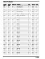
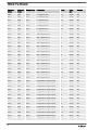
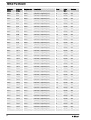
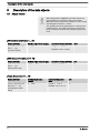
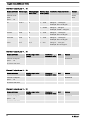
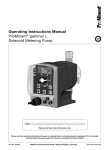
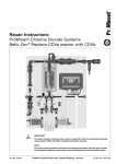
1
Installation and configuration manual
DXCa Modbus RTU – CAN Gateway
V1.2
A1241
These operating instructions are only valid in conjunction with the complete operating instructions DULCOMARIN® II
Please carefully read these operating instructions before use! · Do not discard!
The operator shall be liable for any damage caused by installation or operating errors!
Technical changes reserved.
984723
Target group: Programmers and trained users
BA DC 083 03/14 EN
Supplemental instructions
General non-discriminatory approach
In order to make it easier to read, this document uses the male
form in grammatical structures but with an implied neutral sense. It
is aimed equally at both men and women. We kindly ask female
readers for their understanding in this simplification of the text.
Supplementary information
Please read the supplementary information in its entirety.
The following are highlighted separately in the document:
n Enumerated lists
Instructions
ð Outcome of the instructions
Information
This provides important information relating to the cor‐
rect operation of the device or is intended to make
your work easier.
Safety information
The safety information includes detailed descriptions of the haz‐
ardous situation.
2
Table of contents
Table of contents
1
Introduction........................................................................... 4
1.1 Technical data.............................................................. 5
2
Safety....................................................................................
2.1 Duty to read the user manual.......................................
2.2 Exclusion of plausibility checking of the setpoints........
2.3 Explanation of the safety information............................
2.4 Users' Qualifications ....................................................
3
Commissioning................................................................... 10
3.1 Connectors/fitting ....................................................... 10
3.2 Installation, electrical.................................................. 12
4
Modbus RTU data model ...................................................
4.1 Function codes...........................................................
4.1.1 Function code 3 – [Read Holding Register].............
4.1.2 Function code 6 – Write Single Register..................
4.1.3 Function code 8 - diagnostics..................................
4.1.4 [Modbus exception responses - exception codes]...
4.2 The register range (system image).............................
4.2.1 The system information block..................................
4.2.2 The system configuration block ..............................
4.2.3 Input data block – register 1000 ..............................
4.2.4 Output data block – register 2000 ...........................
4.2.5 Acyclic input data block – register 3000...................
4.2.6 Acyclic output data block – register 4000................
5
Description of the data objects............................................ 44
6
6
6
7
8
13
13
13
14
15
16
17
18
18
18
19
30
37
5.1 Actual values.............................................................. 44
5.2 Control values............................................................. 49
5.3 Error messages.......................................................... 52
6
Acyclic data (3000 and 4000)............................................. 54
6.1 Setpoints..................................................................... 54
6.2 Pause active............................................................... 57
6.3 ECO active.................................................................. 58
7
LEDs and addressing .........................................................
7.1 Rotary coding switches (addressing)..........................
7.1.1 Setting the baud rate...............................................
7.1.2 Setting the parity......................................................
7.1.3 Setting the CAN address.........................................
7.1.4 Setting the Modbus slave address...........................
7.2 LEDs...........................................................................
7.2.1 BF1-LED..................................................................
7.2.2 SF LED....................................................................
7.2.3 BF2-LED..................................................................
7.2.4 RUN-LED.................................................................
59
59
60
60
60
61
61
61
61
62
62
8
Troubleshooting.................................................................. 63
9
Index................................................................................... 64
3
Introduction
1
Introduction
The document is aimed at programmers and personnel
who are involved with planning and commissioning.
This document contains a description of the DXCa-Modbus RTUCAN gateway for communication with the DULCOMARIN® II. The
document should also assist in commissioning the DXCa-Modbus
RTU-CAN gateway. Alongside the description of the hardware and
software components, this document also contains a typical project
created using the development environment [Step 7] from Sie‐
mens. The document is aimed at programmers and personnel who
are involved with planning and commissioning.
This software manual is only valid in combination with the DXCa
gateway described in this document. The DXCa-Gateway may only
be used with DULCOMARIN® II. The content of this document has
been checked for agreement with the described hardware and soft‐
ware. Nevertheless deviations cannot be excluded. Complete
agreement can therefore not be guaranteed.
Revision history
Revision
Date
1
Name
Chapter
Revision
22/04/2013 FR
All
Document created.
1.1
21/06/2013 FR
5
Tables updated with register addresses and remarks.
1.2
07/02/2014 FR
5.2.4
Table title repeated on following pages. Column
"Address (hex.)" inserted.
5.2.5
5.2.6
07/02/2014 FF
4.38.1
Miscellaneous images updated.
Reference to hardware, software and
firmware
Hardware
Device
Revision
DXCa-Modbus RTU-CAN-Gateway
2.3
DULCOMARIN® II
001
Software
Software
Version
HERMES flasher
1
Firmware
Firmware
Firmware version
For the hardware
Gateway firmware
1
DXCa-Modbus-Gateway
Firmware DULCOMARIN® II
From 3022
DULCOMARIN® II
4
Introduction
1.1 Technical data
Properties Modbus-RS485 interface
Description
Parameter
Baud rate
2400 Baud
9600 Baud
19200 Baud
57600 Baud
115200 Baud
Interface type
Potential-free RS-485 interface
Connector
D-sub port, 9 pin
Function codes
FC3, FC6, FC8 (only sub-function code 0)
Characteristic data DXCa gateway
Description
Parameter
Power supply
24V DC
Typical power consumption
approx. 500 mA
Max. number of measured values
116
Weight
250 grams
Dimensions (L x W x H)
117.2 x 45 x 113.5 (mm)
ROHS
yes
CE mark
yes
IP rating
IP20
5
Safety
2
Safety
This document plus all accompanying texts were
written for use by briefed and trained specialist per‐
sonnel. When using this product, all safety instructions
plus the applicable regulations must be observed. The
user must ensure adherence to the legal conditions.
Intended use
The DXCa-Gateway described in this document represents a
MODBUS based interface to the DULCOMARIN® II made by ProM‐
inent®. The DXCa-Gateway may only be operated in conjunction
with the named device and as described in this document. The
DXCa gateway was designed solely to create a connection
between the MODBUS master and the DULCOMARIN® II.
Incorrect use
It is strictly forbidden to use the DXCa gateway in the following
areas:
n for military purposes or in weapons systems
n for the design, construction, maintenance or operation of
nuclear plants
n in flight safety systems, air traffic or flight communications sys‐
tems
n in life support systems
n in systems in which incorrect functioning of the gateway could
result in physical injuries or fatal injuries.
You are advised that the DXCa gateway was not created for use in
dangerous environments, that require fail-safe control mecha‐
nisms. The use of the DXCa gateway in such an environment is at
your own risk, any liability for damage or losses arising from imper‐
missible use is excluded.
2.1 Duty to read the user manual
Before the installation and use of the DXCa gateway described in
this document, you must read and understand all instructions to
avoid damage.
2.2 Exclusion of plausibility checking of the setpoints
At this point it is expressly pointed out that the DXCa MODBUS
CAN gateway does not carry out any plausibility testing of the fedthrough parameters and setpoints.
Checking, alarming or correction of these setpoints does not take
place and is also technically not provided for. In systems, in which
incorrect operation or incorrect setpoint specifications may under
certain circumstances cause damage, the responsibility is that of
the operator, this applies particularly where there is a risk of impair‐
ment to health.
The user/operator must therefore ensure that they personally are
adhering to critical parameters by carrying out regular, manual con‐
trol measurements.
6
Safety
2.3 Explanation of the safety information
Introduction
These operating instructions provide information on the technical
data and functions of the product. These operating instructions pro‐
vide detailed safety information and are provided as clear step-bystep instructions.
The safety information and notes are categorised according to the
following scheme. A number of different symbols are used to
denote different situations. The symbols shown here serve only as
examples.
DANGER!
Nature and source of the danger
Consequence: Fatal or very serious injuries.
Measure to be taken to avoid this danger
Danger!
–
Denotes an immediate threatening danger. If this is
disregarded, it will result in fatal or very serious
injuries.
WARNING!
Nature and source of the danger
Possible consequence: Fatal or very serious injuries.
Measure to be taken to avoid this danger
Warning!
–
Denotes a possibly hazardous situation. If this is
disregarded, it could result in fatal or very serious
injuries.
CAUTION!
Nature and source of the danger
Possible consequence: Slight or minor injuries, mate‐
rial damage.
Measure to be taken to avoid this danger
Caution!
–
Denotes a possibly hazardous situation. If this is
disregarded, it could result in slight or minor inju‐
ries. May also be used as a warning about material
damage.
NOTICE!
Nature and source of the danger
Damage to the product or its surroundings
Measure to be taken to avoid this danger
Note!
–
Denotes a possibly damaging situation. If this is
disregarded, the product or an object in its vicinity
could be damaged.
7
Safety
Type of information
Hints on use and additional information
Source of the information, additional measures
Information!
–
Denotes hints on use and other useful information.
It does not indicate a hazardous or damaging sit‐
uation.
2.4 Users' Qualifications
WARNING!
Danger of injury with inadequately qualified personnel!
If inadequately qualified personnel work on the unit or
loiter in the hazard zone of the unit, this could result in
dangers that could cause serious injuries and material
damage.
–
–
All work on the unit should therefore only be con‐
ducted by qualified personnel.
Unqualified personnel should be kept away from
the hazard zone.
Training
Definition
instructed personnel An instructed person is deemed to be a
person who has been instructed and, if
required, trained in the tasks assigned to
him/her and possible dangers that could
result from improper behaviour, as well as
having been instructed in the required pro‐
tective equipment and protective meas‐
ures.
8
Trained user
A trained user is a person who fulfills the
requirements made of an instructed person
and who has also received additional
training specific to the system from ProMi‐
nent or another authorised distribution
partner.
Technical experts
A technical expert is deemed to be a
person who is able to assess the tasks
assigned to him and recognize possible
hazards based on his/her technical training
and experience, as well as knowledge of
pertinent regulations.
Safety
Training
Definition
Trained qualified
personnel
A qualified employee is deemed to be a
person who is able to assess the tasks
assigned to him and recognize possible
hazards based on his/her training, knowl‐
edge and experience, as well as knowl‐
edge of pertinent regulations. The assess‐
ment of a person's technical training can
also be based on several years of work in
the relevant field.
Electrician
Electricians are deemed to be people, who
are able to complete work on electrical
systems and recognize and avoid possible
hazards independently based on their
technical training and experience, as well
as knowledge of pertinent standards and
regulations.
Electricians should be specifically trained
for the working environment in which they
are employed and know the relevant
standards and regulations.
Electricians must comply with the provi‐
sions of the applicable statutory directives
on accident prevention.
Customer service
department
Customer Service department refers to
service technicians, who have received
proven training and have been authorised
by ProMinent to work on the system.
Note for the system operator
The pertinent accident prevention regulations, as well
as all other generally acknowledged safety regulations,
must be adhered to!
9
Commissioning
3
Commissioning
During commissioning of the DXCa
gateway, please proceed as follows:
1.
Fit the DXCa gateway on a standard top hat rail
2.
Provide the 24V DC power supply
3.
Connect the DXCa gateway to the DULCOMARIN® II using a
CAN M12 connection cable.
4.
Connect the DXCa gateway to the PLC
5.
Set the desired addresses for the CAN bus and MODBUS.
6.
Create a configuration and load the programme in the PLC
memory.
3.1 Connectors/fitting
Klick
2
90°
3
1
A1219
Fig. 1: The DXCa gateway is designed for assembly on standard
top hat rail configurations (e.g. DIN EN 60715, steel, 2000 mm,
galvanized)
10
Commissioning
A1221
Fig. 2: Fitting / removal of the con‐
nector plug (detailed view)
A1220
Fig. 3: Fitting / removal of the connector plug
Power supply
The DXCa gateway has two connection terminals for+24 V and 0 V
(jumpered on the circuit board).
+24V
0V
A1222
Fig. 4: Front view of DXCa gateway (power supply)
11
Commissioning
3.2 Installation, electrical
A1933
Fig. 5: Cabling of the electrical components
The figure shows the cabling of the DXCa Modbus RTU gateway
with a master (e.g. PLC). When connecting a master ensure that
you insert a terminating resistance on each of the end devices in
the bus segment. The DXCa gateway has a switch via which you
can switch the terminating resistance on and off.
A1934
Fig. 6: Plug pin assignments (source: Modbus.org)
Plug pin assignments (source: Modbus.org)
Pin
Name
Description
5
B
Transceiver terminal 1
9
A
Transceiver terminal 0
1
Common
Signal and power supply common (earth)
12
Modbus RTU data model
4
Modbus RTU data model
4.1 Function codes
The DXCa Modbus RTU gateway supports the following function codes:
Function code
Name
Description
3
[Read holding register]
Up to 125 registers can be read with this function
code.
6
[Write single register]
A maximum of one register can be written using this
function code.
8
[Diagnostic (return query data)]
This function code only supports the sub-function code
0.
With function code 8 and sub-function code 0, the
received frame is checked for CRC errors and then
returned to the sender.
4.1.1 Function code 3 – [Read Holding Register]
Up to 125 registers can be read with this function code.
FC 3 - request
Slave address
1 byte
1 – 99
Function code
1 byte
0x03
Start address
2 byte
0x0000 – 0xFFFF
Number of registers
2 byte
1 – 125 (7D)
CRC sum
2 byte
0x0000 – 0xFFFF
Slave address
1 byte
1 – 99
Function code
1 byte
0x03
Number of bytes
1 byte
2 x N*
Register values
N* x 2 byte
CRC sum
2 byte
0x0000 – 0xFFFF
Slave address
1 byte
1 – 99
Function code
1 byte
0x83
Exception code
1 byte
01, 02, 03 or 04
CRC sum
2 byte
0x0000 – 0xFFFF
FC 3 - response
*N = number of registers
FC 3 - error
Example: read 4 registers (2000 to 2003) from the slave with
address 1. The register values and the CRC sum serve purely as
an example for depiction of the frame and may deviate.
13
Modbus RTU data model
FC 3 - example
Request
Response
Name
Value (hex)
Name
Value (hex)
Slave address
0x01
Slave address
0x01
Function code
0x03
Function code
0x03
Start address (high)
0x07
Number of bytes
0x08
Start address (low)
0xd0
Register value 1 (high) register 0x2000
0x00
Number of registers
(high)
0x00
Register value 1 (low) register 0x2000
0x00
Number of registers (low) 0x04
Register value 2 (high) register 0x2001
0x00
CRC (high)
0x44
Register value 2 (low) register 0x2001
0x00
CRC (low)
0x84
Register value 3 (high) register 0x2002
0x00
Register value 3 (low) register 0x2002
0x00
Register value 4 (high) register 0x2003
0x00
Register value 4 (low) register 0x2003
0x00
CRC (high)
0x95
CRC (low)
0xd7
4.1.2 Function code 6 – Write Single Register
You can write a maximum of one register using this function code.
FC 6 - request
Slave address
1 byte
1 – 99
Function code
1 byte
0x06
Register address
2 byte
0x0000 – 0xFFFF
Register value
2 byte
0x0000 – 0xFFFF
CRC sum
2 byte
0x0000 – 0xFFFF
Slave address
1 byte
1 – 99
Function code
1 byte
0x06
Register address
2 byte
0x0000 – 0xFFFF
Register value
2 byte
0x0000 – 0xFFFF
CRC sum
2 byte
0x0000 – 0xFFFF
FC 6 - response
14
Modbus RTU data model
FC 6 - error
Slave address
1 byte
1 – 99
Function code
1 byte
0x86
Exception code
1 byte
01, 02, 03 or 04
CRC sum
2 byte
0x0000 – 0xFFFF
Example: write 1 register (3004) to the slave with address 1. The
register values and the CRC sum serve purely as an example for
depiction of the frame and may deviate.
FC 6 - example
Request
Response
Name
Value (hex)
Name
Value (hex)
Slave address
0x01
Slave address
0x01
Function code
0x06
Function code
0x06
Register address (high)
0x0B
Register address (high)
0x0B
Register address (low)
0xBC
Register address (low)
0xBC
Register value (high)
0x00
Register value 1 (low) register 0x3004
0x00
Register value (low)
0x70
Register value 2 (high) register 0x3004
0x70
CRC (high)
0x4B
CRC (high)
0x4B
CRC (low)
0xEE
CRC (low)
0xEE
4.1.3 Function code 8 - diagnostics
This function code only supports the sub-function code 0. With
function code 8 and sub-function code 0, the received frame is
checked for CRC errors and then returned to the sender.
FC 8 – request
Slave address
1 byte
1 – 99
Function code
1 byte
0x08
Sub-function code
2 byte
0x00
Data
N* x 2 byte
0x0000 – 0xFFFF
CRC sum
2 byte
0x0000 – 0xFFFF
Slave address
1 byte
1 – 99
Function code
1 byte
0x08
Sub-function code
2 byte
0x00
*N = number of data
FC 8 – response
15
Modbus RTU data model
Data
N* x 2 byte
0x0000 – 0xFFFF
CRC sum
2 byte
0x0000 – 0xFFFF
Slave address
1 byte
1 – 99
Function code
1 byte
0x88
Exception code
1 byte
01, 03 or 04
CRC sum
2 byte
0x0000 – 0xFFFF
FC 8 – error
Example: The register values and the CRC sum serve purely as an
example for depiction of the frame and may deviate.
FC 6 - example
Request
Response
Name
Value (hex)
Name
Value (hex)
Slave address
0x01
Slave address
0x01
Function code
0x08
Function code
0x08
Sub-function code (high)
0x00
Sub-function code (high)
0x00
Sub-function code (low)
0x00
Sub-function code (low)
0x00
Data 1
0x01
Data 1
0x01
Data 2
0x02
Data 2
0x02
CRC (high)
0x60
CRC (high)
0x60
CRC (low)
0x5a
CRC (low)
0x5a
4.1.4 [Modbus exception responses - exception codes]
The [exception codes] listed in the previous chapters are interpreted as follows:
Code
Name
Meaning
1
Incorrect function code
The received frame contains a function code that is not supported
by the DXCa Modbus gateway.
2
Incorrect register
address
The register address in the received frame is invalid.
3
Incorrect register value
(data)
The user data transmitted in the frame are invalid for the register to
be described.
4
Service device error
A non-correctable error has occurred during processing of the
query.
16
Modbus RTU data model
4.2 The register range (system image)
The register range of the DXCa Modbus gateway is the central
range through which the interfaces are connected with each other.
The register range has a defined structure and is sub-divided into
various data ranges.
Register range
CAN-Dulcomarin II
0
System information (read only)
MODBUS
RTU
MASTER
99
100
System configuration (write only)
199
200
free
999
1000
Input data (from Modbus RTU to the gateway).
Not allocated (reserve) (write only)
1999
2000
Output data (from the gateway to the Modbus RTU master)
(read only)
2999
3000
Acyclic input data (write only)
This range can only be written to every 4 seconds. If a
faster cycle is used, an error telegram with exception code
4 is sent.
3999
4000
Acyclic output data (read only)
This range can only be read every 4 seconds. If a faster
cycle is used, an error telegram with exception code 4 is
sent.
17
Modbus RTU data model
Register range
4999
The Modbus RTU master can read and write to the various regis‐
ters via the Modbus RTU functions.
4.2.1 The system information block
The DXCa Modbus RTU gateway makes various system informa‐
tion available and this is displayed in the following table.
System information block
Address
Register
Description
Data type
Access
Explanation
0
1
Software version
UINT16
RO
Version of the loaded microcon‐
troller firmware.
1
2
Hardware version UINT16
RO
Hardware revision of the gateway
2
3
Continuous
counter
UINT16
RO
Counts from 0 - 65536, used to
detect whether the gateway is still
working.
3
4
CAN-ID
UINT16
RO
Indicates the CAN BUS ID of the
gateway.
4
5
Error code
UINT16
RO
Display of various errors.
0 = no error
4 = CAN is stopped
5 = CAN is operational
127 = CAN is pre-operational
5
6
Number of pools
6…
7…
Reserve
…99
…100
Reserve
UINT16
RO
The number of pools
4.2.2 The system configuration block
The system configuration block is not currently used and serves as
a reserve.
System configuration block
Address
Register
Description
100…
101…
Reserve
…199
…200
Reserve
Data type
Access
Explanation
4.2.3 Input data block – register 1000
The input data block is not currently used and serves as a reserve.
18
Modbus RTU data model
Input data block
Address
Register
Description
1000…
1001…
Reserve
…1999
…2000
Reserve
Data type
Access
Explanation
4.2.4 Output data block – register 2000
The output data block contains the data for the actual and control
values as well as for the error messages of the individual pools.
These data can be read using Modbus function 3 ‘Read holding
register’ .
Note:
Please note that the various programmes for reading
the measured values differentiate between the Modbus
address and Modbus register. Modbus register 2001 is
located at Modbus address 2000.
Output data
Address
(dec.)
Address
(hex.)
Register
no.
Description
Pool
Data
type
Access
2000
7D0
2001
pH actual value pool
1
INT16
RO
2001
7D1
2002
pH control value pool
1
INT16
RO
2002
7D2
2003
ORP actual value pool
1
INT16
RO
2003
7D3
2004
ORP control value pool
1
INT16
RO
2004
7D4
2005
Temperature actual value pool
1
INT16
RO
2005
7D5
2006
Temperature control value pool
1
INT16
RO
2006
7D6
2007
Channel 4 actual value pool
1
INT16
RO
2007
7D7
2008
Channel 4 control value pool
1
INT16
RO
2008
7D8
2009
Channel 5 actual value pool
1
INT16
RO
2009
7D9
2010
Channel 5 control value pool
1
INT16
RO
2010
7DA
2011
Channel 6 actual value pool
1
INT16
RO
2011
7DB
2012
Channel 6 control value pool
1
INT16
RO
2012
7DC
2013
Channel 7 actual value pool
1
INT16
RO
2013
7DD
2014
Channel 7 control value pool
1
INT16
RO
2014
7DE
2015
Channel 8 actual value pool
1
INT16
RO
2015
7DF
2016
Channel 8 control value pool
1
INT16
RO
2016
7E0
2017
Channel 9 actual value pool
1
INT16
RO
2017
7E1
2018
Channel 9 control value pool
1
INT16
RO
2018
7E2
2019
Channel 10 actual value pool
1
INT16
RO
2019
7E3
2020
Channel 10 control value pool
1
INT16
RO
19
Modbus RTU data model
Address
(dec.)
Address
(hex.)
Register
no.
Description
Pool
Data
type
Access
2020
7E4
2021
Channel 11 actual value pool
1
INT16
RO
2021
7E5
2022
Channel 11 control value pool
1
INT16
RO
2022
7E6
2023
Error pool
1
INT32
RO
2023
7E7
2024
2024
7E8
2025
pH actual value pool
2
INT16
RO
2025
7E9
2026
pH control value pool
2
INT16
RO
2026
7EA
2027
ORP actual value pool
2
INT16
RO
2027
7EB
2028
ORP control value pool
2
INT16
RO
2028
7EC
2029
Temperature actual value pool
2
INT16
RO
2029
7ED
2030
Temperature control value pool
2
INT16
RO
2030
7EE
2031
Channel 4 actual value pool
2
INT16
RO
2031
7EF
2032
Channel 4 control value pool
2
INT16
RO
2032
7F0
2033
Channel 5 actual value pool
2
INT16
RO
2033
7F1
2034
Channel 5 control value pool
2
INT16
RO
2034
7F2
2035
Channel 6 actual value pool
2
INT16
RO
2035
7F3
2036
Channel 6 control value pool
2
INT16
RO
2036
7F4
2037
Channel 7 actual value pool
2
INT16
RO
2037
7F5
2038
Channel 7 control value pool
2
INT16
RO
2038
7F6
2039
Channel 8 actual value pool
2
INT16
RO
2039
7F7
2040
Channel 8 control value pool
2
INT16
RO
2040
7F8
2041
Channel 9 actual value pool
2
INT16
RO
2041
7F9
2042
Channel 9 control value pool
2
INT16
RO
2042
7FA
2043
Channel 10 actual value pool
2
INT16
RO
2043
7FB
2044
Channel 10 control value pool
2
INT16
RO
2044
7FC
2045
Channel 11 actual value pool
2
INT16
RO
2045
7FD
2046
Channel 11 control value pool
2
INT16
RO
2046
7FE
2047
Error pool
2
INT32
RO
2047
7FF
2048
2048
800
2049
pH actual value pool
3
INT16
RO
2049
801
2050
pH control value pool
3
INT16
RO
2050
802
2051
ORP actual value pool
3
INT16
RO
2051
803
2052
ORP control value pool
3
INT16
RO
2052
804
2053
Temperature actual value pool
3
INT16
RO
2053
805
2054
Temperature control value pool
3
INT16
RO
2054
806
2055
Channel 4 actual value pool
3
INT16
RO
2055
807
2056
Channel 4 control value pool
3
INT16
RO
2056
808
2057
Channel 5 actual value pool
3
INT16
RO
20
Modbus RTU data model
Address
(dec.)
Address
(hex.)
Register
no.
Description
Pool
Data
type
Access
2057
809
2058
Channel 5 control value pool
3
INT16
RO
2058
80A
2059
Channel 6 actual value pool
3
INT16
RO
2059
80B
2060
Channel 6 control value pool
3
INT16
RO
2060
80C
2061
Channel 7 actual value pool
3
INT16
RO
2061
80D
2062
Channel 7 control value pool
3
INT16
RO
2062
80E
2063
Channel 8 actual value pool
3
INT16
RO
2063
80F
2064
Channel 8 control value pool
3
INT16
RO
2064
810
2065
Channel 9 actual value pool
3
INT16
RO
2065
811
2066
Channel 9 control value pool
3
INT16
RO
2066
812
2067
Channel 10 actual value pool
3
INT16
RO
2067
813
2068
Channel 10 control value pool
3
INT16
RO
2068
814
2069
Channel 11 actual value pool
3
INT16
RO
2069
815
2070
Channel 11 control value pool
3
INT16
RO
2070
816
2071
Error pool
3
INT32
RO
2071
817
2072
2072
818
2073
pH actual value pool
4
INT16
RO
2073
819
2074
pH control value pool
4
INT16
RO
2074
81A
2075
ORP actual value pool
4
INT16
RO
2075
81B
2076
ORP control value pool
4
INT16
RO
2076
81C
2077
Temperature actual value pool
4
INT16
RO
2077
81D
2078
Temperature control value pool
4
INT16
RO
2078
81E
2079
Channel 4 actual value pool
4
INT16
RO
2079
81F
2080
Channel 4 control value pool
4
INT16
RO
2080
820
2081
Channel 5 actual value pool
4
INT16
RO
2081
821
2082
Channel 5 control value pool
4
INT16
RO
2082
822
2083
Channel 6 actual value pool
4
INT16
RO
2083
823
2084
Channel 6 control value pool
4
INT16
RO
2084
824
2085
Channel 7 actual value pool
4
INT16
RO
2085
825
2086
Channel 7 control value pool
4
INT16
RO
2086
826
2087
Channel 8 actual value pool
4
INT16
RO
2087
827
2088
Channel 8 control value pool
4
INT16
RO
2088
828
2089
Channel 9 actual value pool
4
INT16
RO
2089
829
2090
Channel 9 control value pool
4
INT16
RO
2090
82A
2091
Channel 10 actual value pool
4
INT16
RO
2091
82B
2092
Channel 10 control value pool
4
INT16
RO
2092
82C
2093
Channel 11 actual value pool
4
INT16
RO
2093
82D
2094
Channel 11 control value pool
4
INT16
RO
21
Modbus RTU data model
Address
(dec.)
Address
(hex.)
Register
no.
Description
Pool
Data
type
Access
2094
82E
2095
Error pool
4
INT32
RO
2095
82F
2096
2096
830
2097
pH actual value pool
5
INT16
RO
2097
831
2098
pH control value pool
5
INT16
RO
2098
832
2099
ORP actual value pool
5
INT16
RO
2099
833
2100
ORP control value pool
5
INT16
RO
2100
834
2101
Temperature actual value pool
5
INT16
RO
2101
835
2102
Temperature control value pool
5
INT16
RO
2102
836
2103
Channel 4 actual value pool
5
INT16
RO
2103
837
2104
Channel 4 control value pool
5
INT16
RO
2104
838
2105
Channel 5 actual value pool
5
INT16
RO
2105
839
2106
Channel 5 control value pool
5
INT16
RO
2106
83A
2107
Channel 6 actual value pool
5
INT16
RO
2107
83B
2108
Channel 6 control value pool
5
INT16
RO
2108
83C
2109
Channel 7 actual value pool
5
INT16
RO
2109
83D
2110
Channel 7 control value pool
5
INT16
RO
2110
83E
2111
Channel 8 actual value pool
5
INT16
RO
2111
83F
2112
Channel 8 control value pool
5
INT16
RO
2112
840
2113
Channel 9 actual value pool
5
INT16
RO
2113
841
2114
Channel 9 control value pool
5
INT16
RO
2114
842
2115
Channel 10 actual value pool
5
INT16
RO
2115
843
2116
Channel 10 control value pool
5
INT16
RO
2116
844
2117
Channel 11 actual value pool
5
INT16
RO
2117
845
2118
Channel 11 control value pool
5
INT16
RO
2118
846
2119
Error pool
5
INT32
RO
2119
847
2120
2120
848
2121
pH actual value pool
6
INT16
RO
2121
849
2122
pH control value pool
6
INT16
RO
2122
84A
2123
ORP actual value pool
6
INT16
RO
2123
84B
2124
ORP control value pool
6
INT16
RO
2124
84C
2125
Temperature actual value pool
6
INT16
RO
2125
84D
2126
Temperature control value pool
6
INT16
RO
2126
84E
2127
Channel 4 actual value pool
6
INT16
RO
2127
84F
2128
Channel 4 control value pool
6
INT16
RO
2128
850
2129
Channel 5 actual value pool
6
INT16
RO
2129
851
2130
Channel 5 control value pool
6
INT16
RO
2130
852
2131
Channel 6 actual value pool
6
INT16
RO
22
Modbus RTU data model
Address
(dec.)
Address
(hex.)
Register
no.
Description
Pool
Data
type
Access
2131
853
2132
Channel 6 control value pool
6
INT16
RO
2132
854
2133
Channel 7 actual value pool
6
INT16
RO
2133
855
2134
Channel 7 control value pool
6
INT16
RO
2134
856
2135
Channel 8 actual value pool
6
INT16
RO
2135
857
2136
Channel 8 control value pool
6
INT16
RO
2136
858
2137
Channel 9 actual value pool
6
INT16
RO
2137
859
2138
Channel 9 control value pool
6
INT16
RO
2138
85A
2139
Channel 10 actual value pool
6
INT16
RO
2139
85B
2140
Channel 10 control value pool
6
INT16
RO
2140
85C
2141
Channel 11 actual value pool
6
INT16
RO
2141
85D
2142
Channel 11 control value pool
6
INT16
RO
2142
85E
2143
Error pool
6
INT32
RO
2143
85F
2144
2144
860
2145
pH actual value pool
7
INT16
RO
2145
861
2146
pH control value pool
7
INT16
RO
2146
862
2147
ORP actual value pool
7
INT16
RO
2147
863
2148
ORP control value pool
7
INT16
RO
2148
864
2149
Temperature actual value pool
7
INT16
RO
2149
865
2150
Temperature control value pool
7
INT16
RO
2150
866
2151
Channel 4 actual value pool
7
INT16
RO
2151
867
2152
Channel 4 control value pool
7
INT16
RO
2152
868
2153
Channel 5 actual value pool
7
INT16
RO
2153
869
2154
Channel 5 control value pool
7
INT16
RO
2154
86A
2155
Channel 6 actual value pool
7
INT16
RO
2155
86B
2156
Channel 6 control value pool
7
INT16
RO
2156
86C
2157
Channel 7 actual value pool
7
INT16
RO
2157
86D
2158
Channel 7 control value pool
7
INT16
RO
2158
86E
2159
Channel 8 actual value pool
7
INT16
RO
2159
86F
2160
Channel 8 control value pool
7
INT16
RO
2160
870
2161
Channel 9 actual value pool
7
INT16
RO
2161
871
2162
Channel 9 control value pool
7
INT16
RO
2162
872
2163
Channel 10 actual value pool
7
INT16
RO
2163
873
2164
Channel 10 control value pool
7
INT16
RO
2164
874
2165
Channel 11 actual value pool
7
INT16
RO
2165
875
2166
Channel 11 control value pool
7
INT16
RO
2166
876
2167
Error pool
7
INT32
RO
2167
877
2168
23
Modbus RTU data model
Address
(dec.)
Address
(hex.)
Register
no.
Description
Pool
Data
type
Access
2168
878
2169
pH actual value pool
8
INT16
RO
2169
879
2170
pH control value pool
8
INT16
RO
2170
87A
2171
ORP actual value pool
8
INT16
RO
2171
87B
2172
ORP control value pool
8
INT16
RO
2172
87C
2173
Temperature actual value pool
8
INT16
RO
2173
87D
2174
Temperature control value pool
8
INT16
RO
2174
87E
2175
Channel 4 actual value pool
8
INT16
RO
2175
87F
2176
Channel 4 control value pool
8
INT16
RO
2176
880
2177
Channel 5 actual value pool
8
INT16
RO
2177
881
2178
Channel 5 control value pool
8
INT16
RO
2178
882
2179
Channel 6 actual value pool
8
INT16
RO
2179
883
2180
Channel 6 control value pool
8
INT16
RO
2180
884
2181
Channel 7 actual value pool
8
INT16
RO
2181
885
2182
Channel 7 control value pool
8
INT16
RO
2182
886
2183
Channel 8 actual value pool
8
INT16
RO
2183
887
2184
Channel 8 control value pool
8
INT16
RO
2184
888
2185
Channel 9 actual value pool
8
INT16
RO
2185
889
2186
Channel 9 control value pool
8
INT16
RO
2186
88A
2187
Channel 10 actual value pool
8
INT16
RO
2187
88B
2188
Channel 10 control value pool
8
INT16
RO
2188
88C
2189
Channel 11 actual value pool
8
INT16
RO
2189
88D
2190
Channel 11 control value pool
8
INT16
RO
2190
88E
2191
Error pool
8
INT32
RO
2191
88F
2192
2192
890
2193
pH actual value pool
9
INT16
RO
2193
891
2194
pH control value pool
9
INT16
RO
2194
892
2195
ORP actual value pool
9
INT16
RO
2195
893
2196
ORP control value pool
9
INT16
RO
2196
894
2197
Temperature actual value pool
9
INT16
RO
2197
895
2198
Temperature control value pool
9
INT16
RO
2198
896
2199
Channel 4 actual value pool
9
INT16
RO
2199
897
2200
Channel 4 control value pool
9
INT16
RO
2200
898
2201
Channel 5 actual value pool
9
INT16
RO
2201
899
2202
Channel 5 control value pool
9
INT16
RO
2202
89A
2203
Channel 6 actual value pool
9
INT16
RO
2203
89B
2204
Channel 6 control value pool
9
INT16
RO
2204
89C
2205
Channel 7 actual value pool
9
INT16
RO
24
Modbus RTU data model
Address
(dec.)
Address
(hex.)
Register
no.
Description
Pool
Data
type
Access
2205
89D
2206
Channel 7 control value pool
9
INT16
RO
2206
89E
2207
Channel 8 actual value pool
9
INT16
RO
2207
89F
2208
Channel 8 control value pool
9
INT16
RO
2208
8A0
2209
Channel 9 actual value pool
9
INT16
RO
2209
8A1
2210
Channel 9 control value pool
9
INT16
RO
2210
8A2
2211
Channel 10 actual value pool
9
INT16
RO
2211
8A3
2212
Channel 10 control value pool
9
INT16
RO
2212
8A4
2213
Channel 11 actual value pool
9
INT16
RO
2213
8A5
2214
Channel 11 control value pool
9
INT16
RO
2214
8A6
2215
Error pool
9
INT32
RO
2215
8A7
2216
2216
8A8
2217
pH actual value pool
10
INT16
RO
2217
8A9
2218
pH control value pool
10
INT16
RO
2218
8AA
2219
ORP actual value pool
10
INT16
RO
2219
8AB
2220
ORP control value pool
10
INT16
RO
2220
8AC
2221
Temperature actual value pool
10
INT16
RO
2221
8AD
2222
Temperature control value pool
10
INT16
RO
2222
8AE
2223
Channel 4 actual value pool
10
INT16
RO
2223
8AF
2224
Channel 4 control value pool
10
INT16
RO
2224
8B0
2225
Channel 5 actual value pool
10
INT16
RO
2225
8B1
2226
Channel 5 control value pool
10
INT16
RO
2226
8B2
2227
Channel 6 actual value pool
10
INT16
RO
2227
8B3
2228
Channel 6 control value pool
10
INT16
RO
2228
8B4
2229
Channel 7 actual value pool
10
INT16
RO
2229
8B5
2230
Channel 7 control value pool
10
INT16
RO
2230
8B6
2231
Channel 8 actual value pool
10
INT16
RO
2231
8B7
2232
Channel 8 control value pool
10
INT16
RO
2232
8B8
2233
Channel 9 actual value pool
10
INT16
RO
2233
8B9
2234
Channel 9 control value pool
10
INT16
RO
2234
8BA
2235
Channel 10 actual value pool
10
INT16
RO
2235
8BB
2236
Channel 10 control value pool
10
INT16
RO
2236
8BC
2237
Channel 11 actual value pool
10
INT16
RO
2237
8BD
2238
Channel 11 control value pool
10
INT16
RO
2238
8BE
2239
Error pool
INT32
RO
2239
8BF
2240
2240
8C0
2241
pH actual value pool
11
INT16
RO
2241
8C1
2242
pH control value pool
11
INT16
RO
25
Modbus RTU data model
Address
(dec.)
Address
(hex.)
Register
no.
Description
Pool
Data
type
Access
2242
8C2
2243
ORP actual value pool
11
INT16
RO
2243
8C3
2244
ORP control value pool
11
INT16
RO
2244
8C4
2245
Temperature actual value pool
11
INT16
RO
2245
8C5
2246
Temperature control value pool
11
INT16
RO
2246
8C6
2247
Channel 4 actual value pool
11
INT16
RO
2247
8C7
2248
Channel 4 control value pool
11
INT16
RO
2248
8C8
2249
Channel 5 actual value pool
11
INT16
RO
2249
8C9
2250
Channel 5 control value pool
11
INT16
RO
2250
8CA
2251
Channel 6 actual value pool
11
INT16
RO
2251
8CB
2252
Channel 6 control value pool
11
INT16
RO
2252
8CC
2253
Channel 7 actual value pool
11
INT16
RO
2253
8CD
2254
Channel 7 control value pool
11
INT16
RO
2254
8CE
2255
Channel 8 actual value pool
11
INT16
RO
2255
8CF
2256
Channel 8 control value pool
11
INT16
RO
2256
8D0
2257
Channel 9 actual value pool
11
INT16
RO
2257
8D1
2258
Channel 9 control value pool
11
INT16
RO
2258
8D2
2259
Channel 10 actual value pool
11
INT16
RO
2259
8D3
2260
Channel 10 control value pool
11
INT16
RO
2260
8D4
2261
Channel 11 actual value pool
11
INT16
RO
2261
8D5
2262
Channel 11 control value pool
11
INT16
RO
2262
8D6
2263
Error pool
11
INT32
RO
2263
8D7
2264
2264
8D8
2265
pH actual value pool
12
INT16
RO
2265
8D9
2266
pH control value pool
12
INT16
RO
2266
8DA
2267
ORP actual value pool
12
INT16
RO
2267
8DB
2268
ORP control value pool
12
INT16
RO
2268
8DC
2269
Temperature actual value pool
12
INT16
RO
2269
8DD
2270
Temperature control value pool
12
INT16
RO
2270
8DE
2271
Channel 4 actual value pool
12
INT16
RO
2271
8DF
2272
Channel 4 control value pool
12
INT16
RO
2272
8E0
2273
Channel 5 actual value pool
12
INT16
RO
2273
8E1
2274
Channel 5 control value pool
12
INT16
RO
2274
8E2
2275
Channel 6 actual value pool
12
INT16
RO
2275
8E3
2276
Channel 6 control value pool
12
INT16
RO
2276
8E4
2277
Channel 7 actual value pool
12
INT16
RO
2277
8E5
2278
Channel 7 control value pool
12
INT16
RO
2278
8E6
2279
Channel 8 actual value pool
12
INT16
RO
26
Modbus RTU data model
Address
(dec.)
Address
(hex.)
Register
no.
Description
Pool
Data
type
Access
2279
8E7
2280
Channel 8 control value pool
12
INT16
RO
2280
8E8
2281
Channel 9 actual value pool
12
INT16
RO
2281
8E9
2282
Channel 9 control value pool
12
INT16
RO
2282
8EA
2283
Channel 10 actual value pool
12
INT16
RO
2283
8EB
2284
Channel 10 control value pool
12
INT16
RO
2284
8EC
2285
Channel 11 actual value pool
12
INT16
RO
2285
8ED
2286
Channel 11 control value pool
12
INT16
RO
2286
8EE
2287
Error pool
12
INT32
RO
2287
8EF
2288
2288
8F0
2289
pH actual value pool
13
INT16
RO
2289
8F1
2290
pH control value pool
13
INT16
RO
2290
8F2
2291
ORP actual value pool
13
INT16
RO
2291
8F3
2292
ORP control value pool
13
INT16
RO
2292
8F4
2293
Temperature actual value pool
13
INT16
RO
2293
8F5
2294
Temperature control value pool
13
INT16
RO
2294
8F6
2295
Channel 4 actual value pool
13
INT16
RO
2295
8F7
2296
Channel 4 control value pool
13
INT16
RO
2296
8F8
2297
Channel 5 actual value pool
13
INT16
RO
2297
8F9
2298
Channel 5 control value pool
13
INT16
RO
2298
8FA
2299
Channel 6 actual value pool
13
INT16
RO
2299
8FB
2300
Channel 6 control value pool
13
INT16
RO
2300
8FC
2301
Channel 7 actual value pool
13
INT16
RO
2301
8FD
2302
Channel 7 control value pool
13
INT16
RO
2302
8FE
2303
Channel 8 actual value pool
13
INT16
RO
2303
8FF
2304
Channel 8 control value pool
13
INT16
RO
2304
900
2305
Channel 9 actual value pool
13
INT16
RO
2305
901
2306
Channel 9 control value pool
13
INT16
RO
2306
902
2307
Channel 10 actual value pool
13
INT16
RO
2307
903
2308
Channel 10 control value pool
13
INT16
RO
2308
904
2309
Channel 11 actual value pool
13
INT16
RO
2309
905
2310
Channel 11 control value pool
13
INT16
RO
2310
906
2311
Error pool
13
INT32
RO
2311
907
2312
2312
908
2313
pH actual value pool
14
INT16
RO
2313
909
2314
pH control value pool
14
INT16
RO
2314
90A
2315
ORP actual value pool
14
INT16
RO
2315
90B
2316
ORP control value pool
14
INT16
RO
27
Modbus RTU data model
Address
(dec.)
Address
(hex.)
Register
no.
Description
Pool
Data
type
Access
2316
90C
2317
Temperature actual value pool
14
INT16
RO
2317
90D
2318
Temperature control value pool
14
INT16
RO
2318
90E
2319
Channel 4 actual value pool
14
INT16
RO
2319
90F
2320
Channel 4 control value pool
14
INT16
RO
2320
910
2321
Channel 5 actual value pool
14
INT16
RO
2321
911
2322
Channel 5 control value pool
14
INT16
RO
2322
912
2323
Channel 6 actual value pool
14
INT16
RO
2323
913
2324
Channel 6 control value pool
14
INT16
RO
2324
914
2325
Channel 7 actual value pool
14
INT16
RO
2325
915
2326
Channel 7 control value pool
14
INT16
RO
2326
916
2327
Channel 8 actual value pool
14
INT16
RO
2327
917
2328
Channel 8 control value pool
14
INT16
RO
2328
918
2329
Channel 9 actual value pool
14
INT16
RO
2329
919
2330
Channel 9 control value pool
14
INT16
RO
2330
91A
2331
Channel 10 actual value pool
14
INT16
RO
2331
91B
2332
Channel 10 control value pool
14
INT16
RO
2332
91C
2333
Channel 11 actual value pool
14
INT16
RO
2333
91D
2334
Channel 11 control value pool
14
INT16
RO
2334
91E
2335
Error pool
14
INT32
RO
2335
91F
2336
2336
920
2337
pH actual value pool
15
INT16
RO
2337
921
2338
pH control value pool
15
INT16
RO
2338
922
2339
ORP actual value pool
15
INT16
RO
2339
923
2340
ORP control value pool
15
INT16
RO
2340
924
2341
Temperature actual value pool
15
INT16
RO
2341
925
2342
Temperature control value pool
15
INT16
RO
2342
926
2343
Channel 4 actual value pool
15
INT16
RO
2343
927
2344
Channel 4 control value pool
15
INT16
RO
2344
928
2345
Channel 5 actual value pool
15
INT16
RO
2345
929
2346
Channel 5 control value pool
15
INT16
RO
2346
92A
2347
Channel 6 actual value pool
15
INT16
RO
2347
92B
2348
Channel 6 control value pool
15
INT16
RO
2348
92C
2349
Channel 7 actual value pool
15
INT16
RO
2349
92D
2350
Channel 7 control value pool
15
INT16
RO
2350
92E
2351
Channel 8 actual value pool
15
INT16
RO
2351
92F
2352
Channel 8 control value pool
15
INT16
RO
2352
930
2353
Channel 9 actual value pool
15
INT16
RO
28
Modbus RTU data model
Address
(dec.)
Address
(hex.)
Register
no.
Description
Pool
Data
type
Access
2353
931
2354
Channel 9 control value pool
15
INT16
RO
2354
932
2355
Channel 10 actual value pool
15
INT16
RO
2355
933
2356
Channel 10 control value pool
15
INT16
RO
2356
934
2357
Channel 11 actual value pool
15
INT16
RO
2357
935
2358
Channel 11 control value pool
15
INT16
RO
2358
936
2359
Error pool
15
INT32
RO
2359
937
2360
2360
938
2361
pH actual value pool
16
INT16
RO
2361
939
2362
pH control value pool
16
INT16
RO
2362
93A
2363
ORP actual value pool
16
INT16
RO
2363
93B
2364
ORP control value pool
16
INT16
RO
2364
93C
2365
Temperature actual value pool
16
INT16
RO
2365
93D
2366
Temperature control value pool
16
INT16
RO
2366
93E
2367
Channel 4 actual value pool
16
INT16
RO
2367
93F
2368
Channel 4 control value pool
16
INT16
RO
2368
940
2369
Channel 5 actual value pool
16
INT16
RO
2369
941
2370
Channel 5 control value pool
16
INT16
RO
2370
942
2371
Channel 6 actual value pool
16
INT16
RO
2371
943
2372
Channel 6 control value pool
16
INT16
RO
2372
944
2373
Channel 7 actual value pool
16
INT16
RO
2373
945
2374
Channel 7 control value pool
16
INT16
RO
2374
946
2375
Channel 8 actual value pool
16
INT16
RO
2375
947
2376
Channel 8 control value pool
16
INT16
RO
2376
948
2377
Channel 9 actual value pool
16
INT16
RO
2377
949
2378
Channel 9 control value pool
16
INT16
RO
2378
94A
2379
Channel 10 actual value pool
16
INT16
RO
2379
94B
2380
Channel 10 control value pool
16
INT16
RO
2380
94C
2381
Channel 11 actual value pool
16
INT16
RO
2381
94D
2382
Channel 11 control value pool
16
INT16
RO
2382
94E
2383
Error pool
16
INT32
RO
2383
94F
2384
ECO status pool 1 to 16
-
INT16
RO
2384
950
2385
Pause status pool 1 to 16
-
INT16
RO
…2999
…BB7
…3000
Reserve
29
Modbus RTU data model
4.2.5 Acyclic input data block – register 3000
The acyclic range of the data model includes the setpoints for the
individual pools as well as the values for ‘ECO’ and ‘ Pause
active’ . Write access can be made to these values using Modbus
function code 6.
Write access can only be made to this register once
every 4 seconds, because all values must first be
written via the CAN bus to the Dulcomarin II. If this
condition is not observed, the DXCa Modbus gateway
answers with an error telegram and exception code 4.
NOTICE!
The time until receipt of the Modbus confirmation
(value has been written) can be up to one second.
Moreover for these registers, only one register can be
queried per telegram. If this condition is not observed,
the DXCa gateway answers with an error telegram and
exception code 2.
Note:
Please note that the various programmes for reading
the measured values differentiate between the Modbus
address and Modbus register. Modbus register 2001 is
located at Modbus address 2000.
Acyclic input data block
Address
(dec.)
Address
(hex.)
Register no.
Description
Pool
Data type Access
3000
BB8
3001
pH setpoint pool
1
INT16
WO
3001
BB9
3002
pH setpoint pool
2
INT16
WO
3002
BBA
3003
pH setpoint pool
3
INT16
WO
3003
BBB
3004
pH setpoint pool
4
INT16
WO
3004
BBC
3005
pH setpoint pool
5
INT16
WO
3005
BBD
3006
pH setpoint pool
6
INT16
WO
3006
BBE
3007
pH setpoint pool
7
INT16
WO
3007
BBF
3008
pH setpoint pool
8
INT16
WO
3008
BC0
3009
pH setpoint pool
9
INT16
WO
3009
BC1
3010
pH setpoint pool
10
INT16
WO
3010
BC2
3011
pH setpoint pool
11
INT16
WO
3011
BC3
3012
pH setpoint pool
12
INT16
WO
3012
BC4
3013
pH setpoint pool
13
INT16
WO
3013
BC5
3014
pH setpoint pool
14
INT16
WO
3014
BC6
3015
pH setpoint pool
15
INT16
WO
3015
BC7
3016
pH setpoint pool
16
INT16
WO
30
Modbus RTU data model
Address
(dec.)
Address
(hex.)
Register no.
Description
Pool
Data type Access
3016
BC8
3017
ORP setpoint pool
1
INT16
WO
3017
BC9
3018
ORP setpoint pool
2
INT16
WO
3018
BCA
3019
ORP setpoint pool
3
INT16
WO
3019
BCB
3020
ORP setpoint pool
4
INT16
WO
3020
BCC
3021
ORP setpoint pool
5
INT16
WO
3021
BCD
3022
ORP setpoint pool
6
INT16
WO
3022
BCE
3023
ORP setpoint pool
7
INT16
WO
3023
BCF
3024
ORP setpoint pool
8
INT16
WO
3024
BD0
3025
ORP setpoint pool
9
INT16
WO
3025
BD1
3026
ORP setpoint pool
10
INT16
WO
3026
BD2
3027
ORP setpoint pool
11
INT16
WO
3027
BD3
3028
ORP setpoint pool
12
INT16
WO
3028
BD4
3029
ORP setpoint pool
13
INT16
WO
3029
BD5
3030
ORP setpoint pool
14
INT16
WO
3030
BD6
3031
ORP setpoint pool
15
INT16
WO
3031
BD7
3032
ORP setpoint pool
16
INT16
WO
3032
BD8
3033
Temperature setpoint pool
1
INT16
WO
3033
BD9
3034
Temperature setpoint pool
2
INT16
WO
3034
BDA
3035
Temperature setpoint pool
3
INT16
WO
3035
BDB
3036
Temperature setpoint pool
4
INT16
WO
3036
BDC
3037
Temperature setpoint pool
5
INT16
WO
3037
BDD
3038
Temperature setpoint pool
6
INT16
WO
3038
BDE
3039
Temperature setpoint pool
7
INT16
WO
3039
BDF
3040
Temperature setpoint pool
8
INT16
WO
3040
BE0
3041
Temperature setpoint pool
9
INT16
WO
3041
BE1
3042
Temperature setpoint pool
10
INT16
WO
3042
BE2
3043
Temperature setpoint pool
11
INT16
WO
3043
BE3
3044
Temperature setpoint pool
12
INT16
WO
3044
BE4
3045
Temperature setpoint pool
13
INT16
WO
3045
BE5
3046
Temperature setpoint pool
14
INT16
WO
3046
BE6
3047
Temperature setpoint pool
15
INT16
WO
3047
BE7
3048
Temperature setpoint pool
16
INT16
WO
3048
BE8
3049
Channel 4 setpoint pool
1
INT16
WO
3049
BE9
3050
Channel 4 setpoint pool
2
INT16
WO
3050
BEA
3051
Channel 4 setpoint pool
3
INT16
WO
3051
BEB
3052
Channel 4 setpoint pool
4
INT16
WO
3052
BEC
3053
Channel 4 setpoint pool
5
INT16
WO
31
Modbus RTU data model
Address
(dec.)
Address
(hex.)
Register no.
Description
Pool
Data type Access
3053
BED
3054
Channel 4 setpoint pool
6
INT16
WO
3054
BEE
3055
Channel 4 setpoint pool
7
INT16
WO
3055
BEF
3056
Channel 4 setpoint pool
8
INT16
WO
3056
BF0
3057
Channel 4 setpoint pool
9
INT16
WO
3057
BF1
3058
Channel 4 setpoint pool
10
INT16
WO
3058
BF2
3059
Channel 4 setpoint pool
11
INT16
WO
3059
BF3
3060
Channel 4 setpoint pool
12
INT16
WO
3060
BF4
3061
Channel 4 setpoint pool
13
INT16
WO
3061
BF5
3062
Channel 4 setpoint pool
14
INT16
WO
3062
BF6
3063
Channel 4 setpoint pool
15
INT16
WO
3063
BF7
3064
Channel 4 setpoint pool
16
INT16
WO
3064
BF8
3065
Channel 5 setpoint pool
1
INT16
WO
3065
BF9
3066
Channel 5 setpoint pool
2
INT16
WO
3066
BFA
3067
Channel 5 setpoint pool
3
INT16
WO
3067
BFB
3068
Channel 5 setpoint pool
4
INT16
WO
3068
BFC
3069
Channel 5 setpoint pool
5
INT16
WO
3069
BFD
3070
Channel 5 setpoint pool
6
INT16
WO
3070
BFE
3071
Channel 5 setpoint pool
7
INT16
WO
3071
BFF
3072
Channel 5 setpoint pool
8
INT16
WO
3072
C00
3073
Channel 5 setpoint pool
9
INT16
WO
3073
C01
3074
Channel 5 setpoint pool
10
INT16
WO
3074
C02
3075
Channel 5 setpoint pool
11
INT16
WO
3075
C03
3076
Channel 5 setpoint pool
12
INT16
WO
3076
C04
3077
Channel 5 setpoint pool
13
INT16
WO
3077
C05
3078
Channel 5 setpoint pool
14
INT16
WO
3078
C06
3079
Channel 5 setpoint pool
15
INT16
WO
3079
C07
3080
Channel 5 setpoint pool
16
INT16
WO
3080
C08
3081
Channel 6 setpoint pool
1
INT16
WO
3081
C09
3082
Channel 6 setpoint pool
2
INT16
WO
3082
C0A
3083
Channel 6 setpoint pool
3
INT16
WO
3083
C0B
3084
Channel 6 setpoint pool
4
INT16
WO
3084
C0C
3085
Channel 6 setpoint pool
5
INT16
WO
3085
C0D
3086
Channel 6 setpoint pool
6
INT16
WO
3086
C0E
3087
Channel 6 setpoint pool
7
INT16
WO
3087
C0F
3088
Channel 6 setpoint pool
8
INT16
WO
3088
C10
3089
Channel 6 setpoint pool
9
INT16
WO
3089
C11
3090
Channel 6 setpoint pool
10
INT16
WO
32
Modbus RTU data model
Address
(dec.)
Address
(hex.)
Register no.
Description
Pool
Data type Access
3090
C12
3091
Channel 6 setpoint pool
11
INT16
WO
3091
C13
3092
Channel 6 setpoint pool
12
INT16
WO
3092
C14
3093
Channel 6 setpoint pool
13
INT16
WO
3093
C15
3094
Channel 6 setpoint pool
14
INT16
WO
3094
C16
3095
Channel 6 setpoint pool
15
INT16
WO
3095
C17
3096
Channel 6 setpoint pool
16
INT16
WO
3096
C18
3097
Channel 7 setpoint pool
1
INT16
WO
3097
C19
3098
Channel 7 setpoint pool
2
INT16
WO
3098
C1A
3099
Channel 7 setpoint pool
3
INT16
WO
3099
C1B
3100
Channel 7 setpoint pool
4
INT16
WO
3100
C1C
3101
Channel 7 setpoint pool
5
INT16
WO
3101
C1D
3102
Channel 7 setpoint pool
6
INT16
WO
3102
C1E
3103
Channel 7 setpoint pool
7
INT16
WO
3103
C1F
3104
Channel 7 setpoint pool
8
INT16
WO
3104
C20
3105
Channel 7 setpoint pool
9
INT16
WO
3105
C21
3106
Channel 7 setpoint pool
10
INT16
WO
3106
C22
3107
Channel 7 setpoint pool
11
INT16
WO
3107
C23
3108
Channel 7 setpoint pool
12
INT16
WO
3108
C24
3109
Channel 7 setpoint pool
13
INT16
WO
3109
C25
3110
Channel 7 setpoint pool
14
INT16
WO
3110
C26
3111
Channel 7 setpoint pool
15
INT16
WO
3111
C27
3112
Channel 7 setpoint pool
16
INT16
WO
3112
C28
3113
Channel 8 setpoint pool
1
INT16
WO
3113
C29
3114
Channel 8 setpoint pool
2
INT16
WO
3114
C2A
3115
Channel 8 setpoint pool
3
INT16
WO
3115
C2B
3116
Channel 8 setpoint pool
4
INT16
WO
3116
C2C
3117
Channel 8 setpoint pool
5
INT16
WO
3117
C2D
3118
Channel 8 setpoint pool
6
INT16
WO
3118
C2E
3119
Channel 8 setpoint pool
7
INT16
WO
3119
C2F
3120
Channel 8 setpoint pool
8
INT16
WO
3120
C30
3121
Channel 8 setpoint pool
9
INT16
WO
3121
C31
3122
Channel 8 setpoint pool
10
INT16
WO
3122
C32
3123
Channel 8 setpoint pool
11
INT16
WO
3123
C33
3124
Channel 8 setpoint pool
12
INT16
WO
3124
C34
3125
Channel 8 setpoint pool
13
INT16
WO
3125
C35
3126
Channel 8 setpoint pool
14
INT16
WO
3126
C36
3127
Channel 8 setpoint pool
15
INT16
WO
33
Modbus RTU data model
Address
(dec.)
Address
(hex.)
Register no.
Description
Pool
Data type Access
3127
C37
3128
Channel 8 setpoint pool
16
INT16
WO
3128
C38
3129
Channel 9 setpoint pool
1
INT16
WO
3129
C39
3130
Channel 9 setpoint pool
2
INT16
WO
3130
C3A
3131
Channel 9 setpoint pool
3
INT16
WO
3131
C3B
3132
Channel 9 setpoint pool
4
INT16
WO
3132
C3C
3133
Channel 9 setpoint pool
5
INT16
WO
3133
C3D
3134
Channel 9 setpoint pool
6
INT16
WO
3134
C3E
3135
Channel 9 setpoint pool
7
INT16
WO
3135
C3F
3136
Channel 9 setpoint pool
8
INT16
WO
3136
C40
3137
Channel 9 setpoint pool
9
INT16
WO
3137
C41
3138
Channel 9 setpoint pool
10
INT16
WO
3138
C42
3139
Channel 9 setpoint pool
11
INT16
WO
3139
C43
3140
Channel 9 setpoint pool
12
INT16
WO
3140
C44
3141
Channel 9 setpoint pool
13
INT16
WO
3141
C45
3142
Channel 9 setpoint pool
14
INT16
WO
3142
C46
3143
Channel 9 setpoint pool
15
INT16
WO
3143
C47
3144
Channel 9 setpoint pool
16
INT16
WO
3144
C48
3145
Channel 10 setpoint pool
1
INT16
WO
3145
C49
3146
Channel 10 setpoint pool
2
INT16
WO
3146
C4A
3147
Channel 10 setpoint pool
3
INT16
WO
3147
C4B
3148
Channel 10 setpoint pool
4
INT16
WO
3148
C4C
3149
Channel 10 setpoint pool
5
INT16
WO
3149
C4D
3150
Channel 10 setpoint pool
6
INT16
WO
3150
C4E
3151
Channel 10 setpoint pool
7
INT16
WO
3151
C4F
3152
Channel 10 setpoint pool
8
INT16
WO
3152
C50
3153
Channel 10 setpoint pool
9
INT16
WO
3153
C51
3154
Channel 10 setpoint pool
10
INT16
WO
3154
C52
3155
Channel 10 setpoint pool
11
INT16
WO
3155
C53
3156
Channel 10 setpoint pool
12
INT16
WO
3156
C54
3157
Channel 10 setpoint pool
13
INT16
WO
3157
C55
3158
Channel 10 setpoint pool
14
INT16
WO
3158
C56
3159
Channel 10 setpoint pool
15
INT16
WO
3159
C57
3160
Channel 10 setpoint pool
16
INT16
WO
3160
C58
3161
Channel 11 setpoint pool
1
INT16
WO
3161
C59
3162
Channel 11 setpoint pool
2
INT16
WO
3162
C5A
3163
Channel 11 setpoint pool
3
INT16
WO
3163
C5B
3164
Channel 11 setpoint pool
4
INT16
WO
34
Modbus RTU data model
Address
(dec.)
Address
(hex.)
Register no.
Description
Pool
Data type Access
3164
C5C
3165
Channel 11 setpoint pool
5
INT16
WO
3165
C5D
3166
Channel 11 setpoint pool
6
INT16
WO
3166
C5E
3167
Channel 11 setpoint pool
7
INT16
WO
3167
C5F
3168
Channel 11 setpoint pool
8
INT16
WO
3168
C60
3169
Channel 11 setpoint pool
9
INT16
WO
3169
C61
3170
Channel 11 setpoint pool
10
INT16
WO
3170
C62
3171
Channel 11 setpoint pool
11
INT16
WO
3171
C63
3172
Channel 11 setpoint pool
12
INT16
WO
3172
C64
3173
Channel 11 setpoint pool
13
INT16
WO
3173
C65
3174
Channel 11 setpoint pool
14
INT16
WO
3174
C66
3175
Channel 11 setpoint pool
15
INT16
WO
3175
C67
3176
Channel 11 setpoint pool
16
INT16
WO
3176
C68
3177
ECO active pool
1
INT16
WO
3177
C69
3178
ECO active pool
2
INT16
WO
3178
C6A
3179
ECO active pool
3
INT16
WO
3179
C6B
3180
ECO active pool
4
INT16
WO
3180
C6C
3181
ECO active pool
5
INT16
WO
3181
C6D
3182
ECO active pool
6
INT16
WO
3182
C6E
3183
ECO active pool
7
INT16
WO
3183
C6F
3184
ECO active pool
8
INT16
WO
3184
C70
3185
ECO active pool
9
INT16
WO
3185
C71
3186
ECO active pool
10
INT16
WO
3186
C72
3187
ECO active pool
11
INT16
WO
3187
C73
3188
ECO active pool
12
INT16
WO
3188
C74
3189
ECO active pool
13
INT16
WO
3189
C75
3190
ECO active pool
14
INT16
WO
3190
C76
3191
ECO active pool
15
INT16
WO
3191
C77
3192
ECO active pool
16
INT16
WO
3192
C78
3193
Pause active pool
1
INT16
WO
3193
C79
3194
Pause active pool
2
INT16
WO
3194
C7A
3195
Pause active pool
3
INT16
WO
3195
C7B
3196
Pause active pool
4
INT16
WO
3196
C7C
3197
Pause active pool
5
INT16
WO
3197
C7D
3198
Pause active pool
6
INT16
WO
3198
C7E
3199
Pause active pool
7
INT16
WO
3199
C7F
3200
Pause active pool
8
INT16
WO
3200
C80
3201
Pause active pool
9
INT16
WO
35
Modbus RTU data model
Address
(dec.)
Address
(hex.)
Register no.
Description
Pool
Data type Access
3201
C81
3202
Pause active pool
10
INT16
WO
3202
C82
3203
Pause active pool
11
INT16
WO
3203
C83
3204
Pause active pool
12
INT16
WO
3204
C84
3205
Pause active pool
13
INT16
WO
3205
C85
3206
Pause active pool
14
INT16
WO
3206
C86
3207
Pause active pool
15
INT16
WO
3207
C87
3208
Pause active pool
16
INT16
WO
3208
C88
3209
INPUT 1 product identifier
1
INT16
WO
3209
C89
3210
INPUT 2
2
INT16
WO
3210
C8A
3211
INPUT 3
3
INT16
WO
3211
C8B
3212
INPUT 4
4
INT16
WO
3212
C8C
3213
INPUT 5
5
INT16
WO
3213
C8D
3214
INPUT 6
6
INT16
WO
3214
C8E
3215
INPUT 7
7
INT16
WO
3215
C8F
3216
INPUT 8
8
INT16
WO
3216
C90
3217
INPUT 9
9
INT16
WO
3217
C91
3218
INPUT 10
10
INT16
WO
3218
C92
3219
INPUT 11
11
INT16
WO
3219
C93
3220
INPUT 12
12
INT16
WO
3220
C94
3221
INPUT 13
13
INT16
WO
3221
C95
3222
INPUT 14
14
INT16
WO
3222
C96
3223
INPUT 15
15
INT16
WO
3223
C97
3224
INPUT 16
16
INT16
WO
3224
C98
3225
INPUT 17
17
INT16
WO
3225
C99
3226
INPUT 18
18
INT16
WO
3226
C9A
3227
INPUT 19
19
INT16
WO
3227
C9B
3228
INPUT 20
20
INT16
WO
3228
C9C
3229
INPUT 21
21
INT16
WO
3229
C9D
3230
INPUT 22
22
INT16
WO
3230
C9E
3231
INPUT 23
23
INT16
WO
3231
C9F
3232
INPUT 24
24
INT16
WO
3232
CA0
3233
INPUT 25
25
INT16
WO
3233
CA1
3234
INPUT 26
26
INT16
WO
3234
CA2
3235
INPUT 27
27
INT16
WO
3235
CA3
3236
INPUT 28
28
INT16
WO
3236
CA4
3237
INPUT 29
29
INT16
WO
3237
CA5
3238
INPUT 30
30
INT16
WO
36
Modbus RTU data model
Address
(dec.)
Address
(hex.)
Register no.
Description
Pool
Data type Access
3238
CA6
3239
INPUT 31
31
INT16
WO
3239
CA7
3240
INPUT 32
32
INT16
WO
…3999
…F9F
3241
Reserve
4.2.6 Acyclic output data block – register 4000
The acyclic range of the data model includes the setpoints for the
individual pools as well as the values for ‘ECO’ and ‘ Pause
active’ . Write access can be made to these values using Modbus
function code 3.
Write access can only be made to this register once
every 4 seconds, because all values must first be
written via the CAN bus to the Dulcomarin II. If this
condition is not observed, the DXCa Modbus gateway
answers with an error telegram and exception code 4.
NOTICE!
The time until receipt of the Modbus telegram (return
of the value to be written) can be up to one second.
Moreover for these registers, only one register can be
queried per telegram. If this condition is not observed,
the DXCa gateway answers with an error telegram and
exception code 2.
Note:
Please note that the various programmes for reading
the measured values differentiate between the Modbus
address and Modbus register. Modbus register 2001 is
located at Modbus address 2000.
Acyclic output data block
Address
(dec.)
Address
(hex.)
Register no. Description
Pool
Data
type
Access
4000
FA0
4001
pH setpoint pool
1
INT16
RO
4001
FA1
4002
pH setpoint pool
2
INT16
RO
4002
FA2
4003
pH setpoint pool
3
INT16
RO
4003
FA3
4004
pH setpoint pool
4
INT16
RO
4004
FA4
4005
pH setpoint pool
5
INT16
RO
4005
FA5
4006
pH setpoint pool
6
INT16
RO
4006
FA6
4007
pH setpoint pool
7
INT16
RO
4007
FA7
4008
pH setpoint pool
8
INT16
RO
4008
FA8
4009
pH setpoint pool
9
INT16
RO
37
Modbus RTU data model
Address
(dec.)
Address
(hex.)
Register no. Description
Pool
Data
type
Access
4009
FA9
4010
pH setpoint pool
10
INT16
RO
4010
FAA
4011
pH setpoint pool
11
INT16
RO
4011
FAB
4012
pH setpoint pool
12
INT16
RO
4012
FAC
4013
pH setpoint pool
13
INT16
RO
4013
FAD
4014
pH setpoint pool
14
INT16
RO
4014
FAE
4015
pH setpoint pool
15
INT16
RO
4015
FAF
4016
pH setpoint pool
16
INT16
RO
4016
FB0
4017
ORP setpoint pool
1
INT16
RO
4017
FB1
4018
ORP setpoint pool
2
INT16
RO
4018
FB2
4019
ORP setpoint pool
3
INT16
RO
4019
FB3
4020
ORP setpoint pool
4
INT16
RO
4020
FB4
4021
ORP setpoint pool
5
INT16
RO
4021
FB5
4022
ORP setpoint pool
6
INT16
RO
4022
FB6
4023
ORP setpoint pool
7
INT16
RO
4023
FB7
4024
ORP setpoint pool
8
INT16
RO
4024
FB8
4025
ORP setpoint pool
9
INT16
RO
4025
FB9
4026
ORP setpoint pool
10
INT16
RO
4026
FBA
4027
ORP setpoint pool
11
INT16
RO
4027
FBB
4028
ORP setpoint pool
12
INT16
RO
4028
FBC
4029
ORP setpoint pool
13
INT16
RO
4029
FBD
4030
ORP setpoint pool
14
INT16
RO
4030
FBE
4031
ORP setpoint pool
15
INT16
RO
4031
FBF
4032
ORP setpoint pool
16
INT16
RO
4032
FC0
4033
Temperature setpoint pool
1
INT16
RO
4033
FC1
4034
Temperature setpoint pool
2
INT16
RO
4034
FC2
4035
Temperature setpoint pool
3
INT16
RO
4035
FC3
4036
Temperature setpoint pool
4
INT16
RO
4036
FC4
4037
Temperature setpoint pool
5
INT16
RO
4037
FC5
4038
Temperature setpoint pool
6
INT16
RO
4038
FC6
4039
Temperature setpoint pool
7
INT16
RO
4039
FC7
4040
Temperature setpoint pool
8
INT16
RO
4040
FC8
4041
Temperature setpoint pool
9
INT16
RO
4041
FC9
4042
Temperature setpoint pool
10
INT16
RO
4042
FCA
4043
Temperature setpoint pool
11
INT16
RO
4043
FCB
4044
Temperature setpoint pool
12
INT16
RO
4044
FCC
4045
Temperature setpoint pool
13
INT16
RO
4045
FCD
4046
Temperature setpoint pool
14
INT16
RO
38
Modbus RTU data model
Address
(dec.)
Address
(hex.)
Register no. Description
Pool
Data
type
Access
4046
FCE
4047
Temperature setpoint pool
15
INT16
RO
4047
FCF
4048
Temperature setpoint pool
16
INT16
RO
4048
FD0
4049
Channel 4 setpoint pool
1
INT16
RO
4049
FD1
4050
Channel 4 setpoint pool
2
INT16
RO
4050
FD2
4051
Channel 4 setpoint pool
3
INT16
RO
4051
FD3
4052
Channel 4 setpoint pool
4
INT16
RO
4052
FD4
4053
Channel 4 setpoint pool
5
INT16
RO
4053
FD5
4054
Channel 4 setpoint pool
6
INT16
RO
4054
FD6
4055
Channel 4 setpoint pool
7
INT16
RO
4055
FD7
4056
Channel 4 setpoint pool
8
INT16
RO
4056
FD8
4057
Channel 4 setpoint pool
9
INT16
RO
4057
FD9
4058
Channel 4 setpoint pool
10
INT16
RO
4058
FDA
4059
Channel 4 setpoint pool
11
INT16
RO
4059
FDB
4060
Channel 4 setpoint pool
12
INT16
RO
4060
FDC
4061
Channel 4 setpoint pool
13
INT16
RO
4061
FDD
4062
Channel 4 setpoint pool
14
INT16
RO
4062
FDE
4063
Channel 4 setpoint pool
15
INT16
RO
4063
FDF
4064
Channel 4 setpoint pool
16
INT16
RO
4064
FE0
4065
Channel 5 setpoint pool
1
INT16
RO
4065
FE1
4066
Channel 5 setpoint pool
2
INT16
RO
4066
FE2
4067
Channel 5 setpoint pool
3
INT16
RO
4067
FE3
4068
Channel 5 setpoint pool
4
INT16
RO
4068
FE4
4069
Channel 5 setpoint pool
5
INT16
RO
4069
FE5
4070
Channel 5 setpoint pool
6
INT16
RO
4070
FE6
4071
Channel 5 setpoint pool
7
INT16
RO
4071
FE7
4072
Channel 5 setpoint pool
8
INT16
RO
4072
FE8
4073
Channel 5 setpoint pool
9
INT16
RO
4073
FE9
4074
Channel 5 setpoint pool
10
INT16
RO
4074
FEA
4075
Channel 5 setpoint pool
11
INT16
RO
4075
FEB
4076
Channel 5 setpoint pool
12
INT16
RO
4076
FEC
4077
Channel 5 setpoint pool
13
INT16
RO
4077
FED
4078
Channel 5 setpoint pool
14
INT16
RO
4078
FEE
4079
Channel 5 setpoint pool
15
INT16
RO
4079
FEF
4080
Channel 5 setpoint pool
16
INT16
RO
4080
FF0
4081
Channel 6 setpoint pool
1
INT16
RO
4081
FF1
4082
Channel 6 setpoint pool
2
INT16
RO
4082
FF2
4083
Channel 6 setpoint pool
3
INT16
RO
39
Modbus RTU data model
Address
(dec.)
Address
(hex.)
Register no. Description
Pool
Data
type
Access
4083
FF3
4084
Channel 6 setpoint pool
4
INT16
RO
4084
FF4
4085
Channel 6 setpoint pool
5
INT16
RO
4085
FF5
4086
Channel 6 setpoint pool
6
INT16
RO
4086
FF6
4087
Channel 6 setpoint pool
7
INT16
RO
4087
FF7
4088
Channel 6 setpoint pool
8
INT16
RO
4088
FF8
4089
Channel 6 setpoint pool
9
INT16
RO
4089
FF9
4090
Channel 6 setpoint pool
10
INT16
RO
4090
FFA
4091
Channel 6 setpoint pool
11
INT16
RO
4091
FFB
4092
Channel 6 setpoint pool
12
INT16
RO
4092
FFC
4093
Channel 6 setpoint pool
13
INT16
RO
4093
FFD
4094
Channel 6 setpoint pool
14
INT16
RO
4094
FFE
4095
Channel 6 setpoint pool
15
INT16
RO
4095
FFF
4096
Channel 6 setpoint pool
16
INT16
RO
4096
1000
4097
Channel 7 setpoint pool
1
INT16
RO
4097
1001
4098
Channel 7 setpoint pool
2
INT16
RO
4098
1002
4099
Channel 7 setpoint pool
3
INT16
RO
4099
1003
4100
Channel 7 setpoint pool
4
INT16
RO
4100
1004
4101
Channel 7 setpoint pool
5
INT16
RO
4101
1005
4102
Channel 7 setpoint pool
6
INT16
RO
4102
1006
4103
Channel 7 setpoint pool
7
INT16
RO
4103
1007
4104
Channel 7 setpoint pool
8
INT16
RO
4104
1008
4105
Channel 7 setpoint pool
9
INT16
RO
4105
1009
4106
Channel 7 setpoint pool
10
INT16
RO
4106
100A
4107
Channel 7 setpoint pool
11
INT16
RO
4107
100B
4108
Channel 7 setpoint pool
12
INT16
RO
4108
100C
4109
Channel 7 setpoint pool
13
INT16
RO
4109
100D
4110
Channel 7 setpoint pool
14
INT16
RO
4110
100E
4111
Channel 7 setpoint pool
15
INT16
RO
4111
100F
4112
Channel 7 setpoint pool
16
INT16
RO
4112
1010
4113
Channel 8 setpoint pool
1
INT16
RO
4113
1011
4114
Channel 8 setpoint pool
2
INT16
RO
4114
1012
4115
Channel 8 setpoint pool
3
INT16
RO
4115
1013
4116
Channel 8 setpoint pool
4
INT16
RO
4116
1014
4117
Channel 8 setpoint pool
5
INT16
RO
4117
1015
4118
Channel 8 setpoint pool
6
INT16
RO
4118
1016
4119
Channel 8 setpoint pool
7
INT16
RO
4119
1017
4120
Channel 8 setpoint pool
8
INT16
RO
40
Modbus RTU data model
Address
(dec.)
Address
(hex.)
Register no. Description
Pool
Data
type
Access
4120
1018
4121
Channel 8 setpoint pool
9
INT16
RO
4121
1019
4122
Channel 8 setpoint pool
10
INT16
RO
4122
101A
4123
Channel 8 setpoint pool
11
INT16
RO
4123
101B
4124
Channel 8 setpoint pool
12
INT16
RO
4124
101C
4125
Channel 8 setpoint pool
13
INT16
RO
4125
101D
4126
Channel 8 setpoint pool
14
INT16
RO
4126
101E
4127
Channel 8 setpoint pool
15
INT16
RO
4127
101F
4128
Channel 8 setpoint pool
16
INT16
RO
4128
1020
4129
Channel 9 setpoint pool
1
INT16
RO
4129
1021
4130
Channel 9 setpoint pool
2
INT16
RO
4130
1022
4131
Channel 9 setpoint pool
3
INT16
RO
4131
1023
4132
Channel 9 setpoint pool
4
INT16
RO
4132
1024
4133
Channel 9 setpoint pool
5
INT16
RO
4133
1025
4134
Channel 9 setpoint pool
6
INT16
RO
4134
1026
4135
Channel 9 setpoint pool
7
INT16
RO
4135
1027
4136
Channel 9 setpoint pool
8
INT16
RO
4136
1028
4137
Channel 9 setpoint pool
9
INT16
RO
4137
1029
4138
Channel 9 setpoint pool
10
INT16
RO
4138
102A
4139
Channel 9 setpoint pool
11
INT16
RO
4139
102B
4140
Channel 9 setpoint pool
12
INT16
RO
4140
102C
4141
Channel 9 setpoint pool
13
INT16
RO
4141
102D
4142
Channel 9 setpoint pool
14
INT16
RO
4142
102E
4143
Channel 9 setpoint pool
15
INT16
RO
4143
102F
4144
Channel 9 setpoint pool
16
INT16
RO
4144
1030
4145
Channel 10 setpoint pool
1
INT16
RO
4145
1031
4146
Channel 10 setpoint pool
2
INT16
RO
4146
1032
4147
Channel 10 setpoint pool
3
INT16
RO
4147
1033
4148
Channel 10 setpoint pool
4
INT16
RO
4148
1034
4149
Channel 10 setpoint pool
5
INT16
RO
4149
1035
4150
Channel 10 setpoint pool
6
INT16
RO
4150
1036
4151
Channel 10 setpoint pool
7
INT16
RO
4151
1037
4152
Channel 10 setpoint pool
8
INT16
RO
4152
1038
4153
Channel 10 setpoint pool
9
INT16
RO
4153
1039
4154
Channel 10 setpoint pool
10
INT16
RO
4154
103A
4155
Channel 10 setpoint pool
11
INT16
RO
4155
103B
4156
Channel 10 setpoint pool
12
INT16
RO
4156
103C
4157
Channel 10 setpoint pool
13
INT16
RO
41
Modbus RTU data model
Address
(dec.)
Address
(hex.)
Register no. Description
Pool
Data
type
Access
4157
103D
4158
Channel 10 setpoint pool
14
INT16
RO
4158
103E
4159
Channel 10 setpoint pool
15
INT16
RO
4159
103F
4160
Channel 10 setpoint pool
16
INT16
RO
4160
1040
4161
Channel 11 setpoint pool
1
INT16
RO
4161
1041
4162
Channel 11 setpoint pool
2
INT16
RO
4162
1042
4163
Channel 11 setpoint pool
3
INT16
RO
4163
1043
4164
Channel 11 setpoint pool
4
INT16
RO
4164
1044
4165
Channel 11 setpoint pool
5
INT16
RO
4165
1045
4166
Channel 11 setpoint pool
6
INT16
RO
4166
1046
4167
Channel 11 setpoint pool
7
INT16
RO
4167
1047
4168
Channel 11 setpoint pool
8
INT16
RO
4168
1048
4169
Channel 11 setpoint pool
9
INT16
RO
4169
1049
4170
Channel 11 setpoint pool
10
INT16
RO
4170
104A
4171
Channel 11 setpoint pool
11
INT16
RO
4171
104B
4172
Channel 11 setpoint pool
12
INT16
RO
4172
104C
4173
Channel 11 setpoint pool
13
INT16
RO
4173
104D
4174
Channel 11 setpoint pool
14
INT16
RO
4174
104E
4175
Channel 11 setpoint pool
15
INT16
RO
4175
104F
4176
Channel 11 setpoint pool
16
INT16
RO
4176
1050
4177
ECO active pool
1
INT16
RO
4177
1051
4178
ECO active pool
2
INT16
RO
4178
1052
4179
ECO active pool
3
INT16
RO
4179
1053
4180
ECO active pool
4
INT16
RO
4180
1054
4181
ECO active pool
5
INT16
RO
4181
1055
4182
ECO active pool
6
INT16
RO
4182
1056
4183
ECO active pool
7
INT16
RO
4183
1057
4184
ECO active pool
8
INT16
RO
4184
1058
4185
ECO active pool
9
INT16
RO
4185
1059
4186
ECO active pool
10
INT16
RO
4186
105A
4187
ECO active pool
11
INT16
RO
4187
105B
4188
ECO active pool
12
INT16
RO
4188
105C
4189
ECO active pool
13
INT16
RO
4189
105D
4190
ECO active pool
14
INT16
RO
4190
105E
4191
ECO active pool
15
INT16
RO
4191
105F
4192
ECO active pool
16
INT16
RO
4192
1060
4193
Pause active pool
1
INT16
RO
4193
1061
4194
Pause active pool
2
INT16
RO
42
Modbus RTU data model
Address
(dec.)
Address
(hex.)
Register no. Description
Pool
Data
type
Access
4194
1062
4195
Pause active pool
3
INT16
RO
4195
1063
4196
Pause active pool
4
INT16
RO
4196
1064
4197
Pause active pool
5
INT16
RO
4197
1065
4198
Pause active pool
6
INT16
RO
4198
1066
4199
Pause active pool
7
INT16
RO
4199
1067
4200
Pause active pool
8
INT16
RO
4200
1068
4201
Pause active pool
9
INT16
RO
4201
1069
4202
Pause active pool
10
INT16
RO
4202
106A
4203
Pause active pool
11
INT16
RO
4203
106B
4204
Pause active pool
12
INT16
RO
4204
106C
4205
Pause active pool
13
INT16
RO
4205
106D
4206
Pause active pool
14
INT16
RO
4206
106E
4207
Pause active pool
15
INT16
RO
4207
106F
4208
Pause active pool
16
INT16
RO
…4999
…1387
…5000
43
Description of the data objects
5
Description of the data objects
5.1 Actual values
After starting DULCOMARIN II all actual values are
only available on the Modbus after 130 seconds.
Measured values that are not available or are incorrect
are displayed as 0x7FFF = 32767.
The updating rate of the parameters is 4 seconds per
configured pool. This means that with 10 configured
pools, all measured values are updated every 40 sec‐
onds.
[pH measured variable pool 1 ... 16]
Measured value
Modbus input value (range)
Converted measured value
Unit
[pH measured variable
pool 1 ... 16]
0 ... 1400
Range: 0 ... 14.00
---
Example: 720 = 7.20 pH
(pH actual value)
[ORP measured variable pool 1 - 16]
Measured value
Modbus input value (range)
[ORP measured variable -1200 ... +1200
pool 1 ... 16]
Converted measured value
Unit
-1200 ... 1200 mV
mV
(ORP actual value)
[Temp. Measured pool 1 ... 16]
Measured value
Modbus input value
(range)
Converted measured
value
Unit
[Temp. measured vari‐
able pool 1 ... 16]
0 ... 1200
Range: 0 ... 120 °C
°C
(Temperature actual
value)
44
Example: 130 = 13.0 °C
Description of the data objects
The interpretation of the data changes dependent on the identity
code. The following data are consecutively numbered starting with
number 4 and thus do not have the actual names of their user
data.
[Ch. 4 measured variable pool 1 ... 16]
Measured value Sensor type
DXCa identity
code
Modbus input
value (range)
Converted measured
value
Unit
S, C, D
0 ... 1000
Range 0 ... 10.00 ppm
ppm
[Ch. 4 meas‐
ured variable
pool 1 ... 16 ]
(Channel 4
actual value)
Cl
CLE 3
Example: 200 = 2.00
ppm
0 ... 20000
Range 0 ... 200 ppm
ppm
Example: 10000 = 100
ppm
CGE
S, D
0 ... 1000
Range 0 ... 10.00 ppm
ppm
Example: 200 = 2.00
ppm
CLE 3.1
0 ... 1000
Range 0 ... 10.00 ppm
ppm
Example: 200 = 2.00
ppm
Cl free
0 ... 1000
Range 0 ... 10.00 ppm
ppm
Example: 200 = 2.00
ppm
Br
0 ... 1000
Range 0 ... 10.00 ppm
ppm
Example: 200 = 2.00
ppm
ClO2
CDR
S, D
0 ... 200
Range 0 ... 2.00 ppm
ppm
Example: 50 = 0.50
ppm
[Ch. 5 measured variable pool 1 ... 16]
Measured value Sensor type
DXCa identity
code ‘Use’
Modbus input
value (range)
Converted measured
value
Unit
C
0 ... 1000
Range 0 ... 10.00 ppm
ppm
[Ch. 5 meas‐
ured variable
pool1 ... 16]
(Channel 5
actual value)
Cl
CLE 3
Example: 200 = 2.00
ppm
45
Description of the data objects
Measured value Sensor type
DXCa identity
code ‘Use’
Modbus input
value (range)
Converted measured
value
Unit
0 ... 20000
Range 0 ... 200 ppm
ppm
Example: 10000 = 100
ppm
Cl total
CTE
D
0 ... 1000
Range 0 ... 10.00 ppm
ppm
Example: 200 = 2.00
ppm
Cl bound
CTE
S
0 ... 1000
Range 0 ... 10.00 ppm
ppm
Example: 200 = 2.00
ppm
ClO2-
CLT
S, D
0 ... 200
Range 0 ... 2.00 ppm
ppm
Example: 50 = 0.50
ppm
[Ch. 6 measured variable pool 1 ... 16]
Measured value Sensor type
DXCa identity
code ‘Use’
Modbus input
value (range)
Converted measured
value
Unit
S
0 ... 1000
Range 0 ... 10.00 ppm
ppm
[Ch. 6 meas‐
ured variable
pool 1 ... 16 ]
(Channel 6
actual value)
Cl total
CTE
Example: 200 = 2.00
ppm
Cl bound
CTE
D
0 ... 1000
Range 0 ... 10.00 ppm
Example: 200 = 2.00
ppm
[Ch. 7 measured variable pool 1 ... 16]
Measured value
[Ch. 7 measured variable pool
1 ... 16]
(Channel 7 actual value)
Ht. above sea level
46
Modbus input value (range)
Converted measured
value
Unit
ppm
Description of the data objects
[Ch. 8 measured variable pool 1 ... 16]
Measured value
Modbus input value (range)
Converted measured
value
Unit
Modbus input value (range)
Converted measured
value
Unit
I1 (edit mode)
0 ... 9999
Dependent on the edited value in the I
module
Q
0 ... 9999
see device formatting
m³/h, l/h
Converted measured
value
Unit
[Ch. 8 measured variable
pool 1 ... 16]
(Channel 8 actual value)
CANopen turbidity sensor
[Ch. 9 measured variable pool 1 ... 16]
Measured value
[Ch. 9 measured variable
pool 1 ... 16 ]
(Channel 9 actual value)
[Ch. 10 measured variable pool 1 ... 16]
Measured value
Modbus input value (range)
[Ch. 10 measured variable
pool 1 ... 16]
(Channel 10 actual value)
I2 (edit mode)
0 ... 9999
mA
Ammonia (NH3)
0 ... 9999
ppm, mg/l
Hydrogen peroxide (H2O2)
0 ... 9999
ppm, mg/l
Peracetic acid (PES)
0 ... 9999
ppm, mg/l
Conductive conductivity
0 ... 9999
µS/cm, mS/cm,
S/cm
ClO2
0 ... 9999
ppm, mg/l
DO
0 ... 9999
ppm, mg/l
47
Description of the data objects
[Ch. 11 measured variable pool 1 ... 16]
Measured value
Modbus input value
(range)
Converted measured
value
Unit
[Ch. 11 measured vari‐
able pool 1 ... 16]
(Channel 11 actual
value)
I3 (edit mode)
mA
PES
0 ... 9999
ppm/mg/l
Temperature
0 ... 9999
°C
ClO2-
0 ... 9999
ppm/mg/l
UV intensity (UV)
0 ... 9999
W/m², mW/cm²
Turbidity
0 ... 9999
FNU, NTU, FTU, FAU,
EBC
48
Description of the data objects
5.2 Control values
After starting DULCOMARIN II all actual values are
only available on the Modbus after 130 seconds.
Measured values that are not available or are incorrect
are displayed as 0x7FFF = 32767.
The updating rate of the parameters is 4 seconds per
configured pool. This means that with 10 configured
pools, all measured values are updated every 40 sec‐
onds.
[pH control output pool 1 ... 16]
Measured value
Modbus input value (range)
Converted measured
value
Unit
[pH control output pool 1 ... 16]
-1000 ... 0 ... 1000
Range: 0 ... 14.00
%
(pH control value)
Example: 720 = 7.20 pH
[ORP control output pool 1 ... 16]
Measured value
Modbus input value (range)
Converted measured
value
Unit
[ORP control output pool 1 ...
16]
-1000 ... 0 ... 1000
-1200 ... 1200 mV
%
(ORP control value)
[Tem. Control output pool 1 ... 16]
Measured value
Modbus input value (range)
Converted measured
value
Unit
[Temp. control output pool 1 ...
16 ]
0 ... 1000
Range: 0 ... 120 °C
°C
(Temperature control value)
Example: 130 = 13.0 °C
49
Description of the data objects
Interpretation of the data
Dependent upon whether the DULCOMARIN II is
equipped with the various modules, the interpretation
of the data changes. The following data are consecu‐
tively numbered starting with number 4 and thus do not
have the actual names of their user data.
[Ch. 4 control output pool 1 ... 16]
Measured value
Modbus input value (range)
Converted measured
value
Unit
[Ch. 4 control output pool 1...
16]
(Channel 4 control value)
Cl, Br, ClO2,…
0 ... 1000
%
[Ch. 5 control output pool 1 ... 16]
Measured value
Modbus input value (range)
Converted measured
value
Unit
[Ch. 5 control output pool 1 ...
16]
(Channel 5 control value)
Cl bound
-1000 ... 0
%
ClO2-
-1000 ... 0
%
[Ch. 6 control output pool 1 ... 16]
Measured value
Modbus input value (range)
Converted measured
value
Unit
[Ch. 6 control output pool 1 ...
16 ]
(Channel 6 control value)
Ht. above sea level
0 ... 1000
%
[Ch. 7 control output pool 1 ... 16]
Measured value
Modbus input value (range)
Converted measured
value
Unit
[Ch. 7 control output pool 1 ...
16]
(Channel 7 control value)
FLOCK
50
0 ... 1000
%
Description of the data objects
[Ch. 8 control output pool 1 ... 16]
Measured value
Modbus input value (range)
Converted measured
value
Unit
[Ch. 8 control output pool 1 ...
16]
(Channel 8 control value)
Ht. above sea level
0 ... 1000
%
[Ch. 9 control output pool 1 ... 16]
Measured value
Modbus input value (range)
Converted measured
value
Unit
[Ch. 9 control output pool 1 ...
16]
(Channel 8 control value)
Ht. above sea level
%
[Ch. 10 control output pool 1 ... 16]
Measured value
Modbus input value (range)
Converted measured
value
Unit
[Ch. 10 control output pool 1 ...
16]
(Channel 10 control value)
I2 (edit mode)
0 ... 1000
%
Ammonia (NH3)
0 ... 1000
%
Hydrogen peroxide (H2O2)
0 ... 1000
%
Peracetic acid (PES)
0 ... 1000
%
Conductive conductivity
0 ... 1000
%
ClO2
0 ... 1000
%
DO
0 ... 1000
%
[Ch. 11 control output pool 1 ... 16]
Measured value
Modbus input value (range)
Converted measured
value
Unit
[Ch. 11 control output pool 1 ...
16 ]
(Channel 11 control value)
Ht. above sea level
%
51
Description of the data objects
5.3 Error messages
Error messages are coded as a bit field.
Error messages
No.
Description
1
Error pool 1 (32 Bit)
…
16
Error pool 16 (32 Bit)
Decoding of the error messages
Number
Description
pH actual value channel 1 bit: 0
= 0x00000001 pH measured value invalid
pH actual value channel 1 bit: 1
= 0x00000002 pH measured value min.
pH actual value channel 1 bit: 2
= 0x00000004 pH measured value max.
Channel 2 bit: 3
= 0x00000008 measured value invalid
Channel 2 bit: 4
= 0x00000010 measured value min.
Channel 2 bit: 5
= 0x00000020 measured value max.
Channel 3 bit: 6
= 0x00000040 measured value invalid
Channel 3 bit: 7
= 0x00000080 measured value min.
Channel 3 bit: 8
= 0x00000100 measured value max.
Channel 4 bit: 9
= 0x00000200 measured value invalid
Channel 4 bit: 10
= 0x00000400 measured value min.
Channel 4 bit: 11
= 0x00000800 measured value max.
Channel 5 bit: 12
= 0x00001000 measured value invalid
Channel 5 bit: 13
= 0x00002000 measured value min.
Channel 5 bit: 14
= 0x00004000 measured value max.
Channel 10 bit: 15
= 0x00008000 measured value invalid
Channel 10 bit: 16
= 0x00010000 measured value min.
Channel 10 bit: 17
= 0x00020000 measured value max.
Channel 11 bit: 18
= 0x00040000 measured value invalid
Channel 11 bit: 19
= 0x00080000 measured value min.
Channel 11 bit: 20
= 0x00100000 measured value max.
Bit 21
= 0x00200000 sample water error
Free bit: 22
= 0x00400000
Free bit: 23
= 0x00800000
Free bit: 24
= 0x01000000
Free bit: 25
= 0x02000000
DXMaA bit: 26
= 0x04000000 error
52
Description of the data objects
Number
Description
DXMaR bit: 27
= 0x08000000 control valve not ready
DP1 bit: 28
= 0x10000000 metering pump error active
DP2 bit: 29
= 0x20000000 metering pump error active
DP3 bit: 30
= 0x40000000 metering pump error active
DP4 bit: 31
= 0x80000000 metering pump error active
No error
= 0x00000000
53
Acyclic data (3000 and 4000)
6
Acyclic data (3000 and 4000)
The following setpoints are only available via acyclic Modbus RTU
traffic and start at Register 0x3000 (acyclic input data) and 0x4000
(acyclic output data).
6.1 Setpoints
pH setpoint pool 1 ... 16
Measured value
Modbus input value
(range)
Converted measured
value
Unit
Access
pH setpoint
0 ... 1400
Range: 0 ... 14.00
---
Read/write
pool 1 ... 16
Example: 720 = 7.20 pH
ORP setpoint pool 1 ... 16
Measured value
Modbus input value
(range)
Converted measured value Unit
Access
ORP setpoint
-1200 ... +1200
-1200 ... 1200 mV
Read/write
mV
pool 1 ... 16
Temperature setpoint pool 1 ... 16
Measured value
Modbus input value
(range)
Converted measured value
Unit
Access
Temperature set‐
point
0 ... 1200
Range: 0 ... 120 °C
°C
Read/write
pool 1 ... 16
54
Example: 130 = 13.0 °C
Acyclic data (3000 and 4000)
Interpretation of the data
Dependent upon whether the DULCOMARIN II is
equipped with the various modules, the interpretation
of the data changes. The following data are consecu‐
tively numbered starting with number 4 and thus do not
have the actual names of their user data.
Channel 4 setpoint pool 1 ... 16
Measured value Sensor type
DXCa iden‐
tity code
Modbus input
value (range)
Converted measured value
Channel 4 set‐
point
Access
Read/write
pool 1 ... 16
Cl
CLE 3
S, C, D
0 ... 1000
Range 0 ... 10.00 ppm
Example: 200 = 2.00 ppm
0 ... 20000
Range 0 .. 200 ppm
Example: 10000 = 100 ppm
CGE
S, D
0 ... 1000
Range 0 ... 10.00 ppm
Example: 200 = 2.00 ppm
CLE 3.1
0 ... 1000
Range 0 ... 10.00 ppm
Example: 200 = 2.00 ppm
Cl free
0 ... 1000
Range 0 ... 10.00 ppm
Example: 200 = 2.00 ppm
Br
0 ... 1000
Range 0 ... 10.00 ppm
Example: 200 = 2.00 ppm
ClO2
CDR
S, D
0 ... 200
Range 0 ... 2.00 ppm
Example: 50 = 0.50 ppm
55
Acyclic data (3000 and 4000)
Channel 5 setpoint pool 1 ... 16
Measured value Sensor type
DXCa identity
code "Use"
Modbus input Converted measured value
value (range)
Channel 5 set‐
point
Access
Read/
write
pool 1 ... 16
Cl
CLE 3
C
0 ... 1000
Range 0 ... 10.00 ppm
Example: 200 = 2.00 ppm
0 ... 20000
Range 0 ... 200 ppm
Example: 10000 = 100 ppm
Cl total
CTE
D
0 ... 1000
Range 0 ... 10.00 ppm
Example: 200 = 2.00 ppm
Cl bound
CTE
S
0 ... 1000
Range 0 ... 10.00 ppm
Example: 200 = 2.00 ppm
ClO2-
CLT
S, D
0 ... 200
Range 0 ... 2.00 ppm
Example: 50 = 0.50 ppm
Channel 6 setpoint pool 1 ... 16
Measured value
Modbus input value
(range)
Converted
measured value
Unit
Channel 6 setpoint
Access
Read/write
pool 1 ... 16
Ht. above sea level
Channel 7 setpoint pool 1 ... 16
Measured value
Modbus input value
(range)
Converted
measured value
Unit
Channel 7 setpoint
Access
Read/write
pool 1 ... 16
Ht. above sea level
Channel 8 setpoint pool 1 ... 16
Measured value
Channel 8 setpoint
pool 1 ... 16
Ht. above sea level
56
Modbus input value
(range)
Converted
measured value
Unit
Access
Read/write
Acyclic data (3000 and 4000)
Channel 9 setpoint pool 1 ... 16
Measured value
Modbus input value
(range)
Converted
measured value
Unit
Channel 9 setpoint
Access
Read/write
pool 1 ... 16
Ht. above sea level
Channel 10 setpoint pool 1 ... 16
Measured value
Modbus input value (range)
Converted measured
value
Channel 10 setpoint pool
1 ... 16
Access
Read/write
I2 (edit mode)
0 ... 9999
Ammonia (NH3)
0 ... 9999
Hydrogen peroxide
(H2O2)
0 ... 9999
Peracetic acid (PES)
0 ... 9999
Conductive conductivity
0 ... 9999
ClO2
0 ... 9999
DO
0 ... 9999
Channel 11 setpoint pool 1 ... 16
Measured value
Modbus input value
(range)
Converted
measured value
Channel 11 setpoint
Unit
Access
Read/write
pool 1 ... 16
Ht. above sea level
6.2 Pause active
Pause active
Measured value
Pause
Modbus input value Converted meas‐
(range)
ured value
Unit
Access
Read/write
pool 1 ... 16
Pause active = 1
Pause inactive = 0
Under pause inactive, the corresponding field contains a 0.
57
Acyclic data (3000 and 4000)
6.3 ECO active
Pause active
Measured value
ECO! mode
Modbus input value Converted meas‐
(range)
ured value
Unit
Access
Read/write
pool 1 ... 16
ECO! mode
active = 1
inactive = 0
Under ECO inactive, the corresponding field contains a 0.
After starting DULCOMARIN II all setpoints are only
available on the Modbus after 130 seconds.
58
LEDs and addressing
7
LEDs and addressing
The chapter describes the meaning of the LEDs and the settings
for the rotary coding switches.
7.1 Rotary coding switches (addressing)
1.
2.
3.
4.
13.
12.
11.
5.
10.
6.
9.
7.
8.
A1935
Fig. 7: Rotary coding switches (addressing) / device view
1.
2.
3.
4.
5.
6.
7.
SF LED
BF1-LED
BF2-LED
RUN-LED
M12 CAN bus connector
CAN bus address
[Modbus slave address x10]
8.
9.
10.
11.
12.
13.
[Modbus slave address x1]
DSub Modbus RS485
RX-TX LED
Modbus bus connector
Parity
Baud rate
59
LEDs and addressing
7.1.1 Setting the baud rate
The baud rate for the serial Modbus connection can be set as fol‐
lows:
Setting the baud rate
Number
Baud rate in baud
1
2400
2
9600
3
19200
4
57600
5
115200
0, 6, 7, 8, 9
115200
7.1.2 Setting the parity
The parity for the serial Modbus connection can be set as follows:
Setting the parity
Number
Parity
0
No parity
1
No parity
2
Even parity
3
Odd parity
4, 5, 6, 7, 8, 9
No parity
7.1.3 Setting the CAN address
The CAN address can be set as follows:
Setting the CAN address
Number
Address
0
0
1, 2, 3, 4
5
5
5
6
6
7, 8, 9
5
60
LEDs and addressing
7.1.4 Setting the Modbus slave address
The Modbus slave address can be set from 1 ... 99.
Setting the Modbus slave address
Number
Address
0
Not specified
1 ... 99
According to the rotary coding switch
7.2 LEDs
7.2.1 BF1-LED
Communication LED (bus error 1). This LED describes the condi‐
tion of the primary communication protocol.
BF1-LED
LED
Colour
Status
Meaning
BF1
LED (red)
Red
Cyclical flashing
STOP, error in communi‐
cation
-
OFF
OK
7.2.2 SF LED
Collective error LED This LED describes gateway errors
SF1-LED
LED
Colour
Status
Meaning
SF1
LED (red)
Red
ON
General error: Error of
the primary or secondary
communications system.
-
OFF
OK
61
LEDs and addressing
7.2.3 BF2-LED
Communication LED (bus error 2). This LED describes the condi‐
tion of the secondary (CAN) communication protocol.
BF2-LED
LED
Colour
Status
Meaning
BF2
LED (red)
Red
Cyclical flashing
Error CAN bus. No DUL‐
COMARIN II connected
or connection faulty.
-
OFF
OK
7.2.4 RUN-LED
The RUN-LED informs about the error-free state of the gateway.
RUN-LED
LED
Colour
BF2
LED (green)
62
Status
Meaning
green
ON
OK
-
OFF
Error. See error LEDs
SF, BF1 or BF2.
Troubleshooting
8
Troubleshooting
Signalisation
Possible errors
Remedy
None of the LEDs illuminates
or flashes.
No 24V voltage supply.
Ensure that the gateway has a 24V supply.
Device defective.
Check the polarity of the input voltage.
BF1 illuminates.
Faulty connection to the
Modbus master.
Check the bus cable for short circuits or
breaks.
Check whether the terminating resistances
are switched on at the first and last bus
members.
Check and change the transmission rate
(e.g. in the Step 7)
BF2 illuminate or flashes.
No or faulty physical con‐
nection to the DULCO‐
MARIN II.
Check the CAN bus cable for short circuits
and breaks.
Faulty Modbus connection
or no CAN bus connection.
Check the CAN bus cable for short circuits
and breaks.
Internal error.
Check whether the terminating resistances
are set at the first and last CAN members.
One or more measured
values indicate the value
"0x7FFF or 32767".
This value means that the
measured value does not
exist. You have selected a
measured value that is not
available in the DULCO‐
MARIN II.
Adjust your configuration (e.g. in the Step 7).
The DXCa Modbus gateway
is not responding to a tele‐
gram
Incorrect Modbus address
set.
Check the address at the gateway and in
your master application.
Incorrect CRC sum.
Check the calculation of the CRC sum.
(CAN bus error).
SF illuminates.
Check whether the terminating resistances
are set at the first and last CAN members.
63
Index
9
Index
A
Intended use.......................................................... 6
Acyclic data.......................................................... 54
Acyclic input data block........................................ 30
Addressing........................................................... 59
C
Cabling of the electrical components................... 12
Characteristic data DXCa gateway........................ 5
Checking, alarming or correction of these set‐
points...................................................................... 6
E
Exception codes................................................... 16
F
FC 3 - error........................................................... 13
FC 3 - example..................................................... 14
FC 3 - request...................................................... 13
FC 3 - response................................................... 13
FC 6 - error........................................................... 15
FC 6 - example............................................... 15, 16
FC 6 - request...................................................... 14
FC 6 - response................................................... 14
FC 8 – error.......................................................... 16
FC 8 – request...................................................... 15
FC 8 – response................................................... 15
Firmware................................................................ 4
Function codes..................................................... 13
G
General non-discriminatory approach.................... 2
GSD file.................................................................. 4
H
HERMES flasher.................................................... 4
I
Incorrect use.......................................................... 6
Input data block.................................................... 19
L
LEDs.................................................................... 59
N
Non-discriminatory approach................................. 2
P
Plausibility checking of the setpoints..................... 6
Plug pin assignments (source: Modbus.org)........ 12
Possible errors..................................................... 63
Power supply........................................................ 10
Properties Modbus-RS485 interface...................... 5
R
Reference to hardware, software and firmware..... 4
Remedy................................................................ 63
Revision history...................................................... 4
S
Safety information.................................................. 7
Setpoints.............................................................. 54
Setting the baud rate............................................ 60
Setting the CAN address...................................... 60
Setting the Modbus slave address....................... 61
Setting the parity.................................................. 60
Setting values for the rotary coding switches....... 59
Software................................................................. 4
System configuration block.................................. 18
System information block..................................... 18
T
Troubleshooting................................................... 63
U
Users' qualifications .............................................. 8
64
65
66
67
ProMinent GmbH
Im Schuhmachergewann 5 - 11
69123 Heidelberg
Telephone: +49 6221 842-0
Fax: +49 6221 842-419
email: [email protected]
Internet: www.prominent.com
984723, 1, en_GB
© 2014