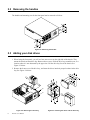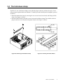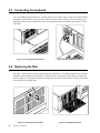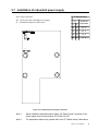
1
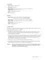
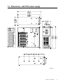
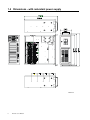
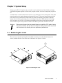
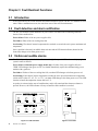
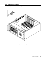
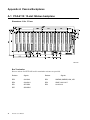
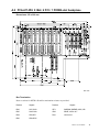
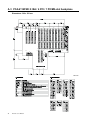
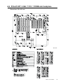
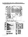
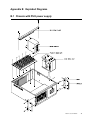
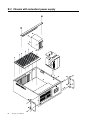
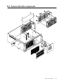
IPC-615
15-slot Fault-resilient
IPC Chassis
User's Manual
Copyright notice
This document is copyrighted, November 1999, by Advantech Co., Ltd. All rights are reserved. Advantech Co., Ltd. reserves the right to make improvements to the products described in this manual at any
time without notice.
No part of this manual may be reproduced, copied, translated or transmitted in any form or by any
means without the prior written permission of Advantech Co., Ltd. Information provided in this
manual is intended to be accurate and reliable. However, Advantech Co., Ltd. assumes no responsibility for its use, nor for any infringements of the rights of third parties which may result from its use.
Acknowledgments
IPC-615, PCA-6115, PCA-6114P4, PCA-6114, PCA-6114P4R, PCA-6114P7 and PCA-6114P10 are all
trademarks of Advantech Co., Ltd.
Note:
The information in this manual is provided for reference only. Advantech does not
assume any liability arising out of the application or use of the information or
products described herein. This manual is subject to change without notice.
Part No. 2002061500
5th Edition Printed in Taiwan November 1999
Contents
Chapter 1 General Information ..................................................... 1
1.1
1.2
Introduction ........................................................................................1
Specifications ....................................................................................1
General ...........................................................................................................................
Passive backplanes .......................................................................................................
Power supplies ..............................................................................................................
Environmental specifications ......................................................................................
1.3
1.4
1
1
2
4
Dimensions - with PS/2 power supply ...............................................5
Dimensions - with redundant power supply .......................................6
Chapter 2 System Setup ............................................................... 7
2.1
2.2
2.3
2.4
2.5
2.6
2.7
Removing the cover ...........................................................................7
Removing the handles .......................................................................8
Adding your disk drives .....................................................................8
The hold-down clamp ........................................................................9
Connecting the keyboard .................................................................10
Replacing the filter ...........................................................................10
Installation of redundant power supply ............................................11
Chapter 3 Fault Resilient Functions .......................................... 12
3.1
3.2
3.3
3.4
Introduction ......................................................................................12
Fault detection and alarm notification ..............................................12
Visible and audible alarms ...............................................................12
Overheating sensor .........................................................................13
Appendix A Passive Backplanes ............................................... 14
A.1
A.2
A.3
A.4
A.5
PCA-6115: 15-slot ISA-bus backplane ............................................14
PCA-6114P4: 9 ISA / 4 PCI / 1 PICMG-slot backplane ...................15
PCA-6114P4R: 9 ISA / 4 PCI / 1 PICMG-slot backplane ................16
PCA-6114P7: 6 ISA / 7 PCI / 1 PICMG-slot backplane ...................17
PCA-6114P10: 3 ISA / 10 PCI / 1 PICMG-slot backplane ...............18
Appendix B Exploded Diagrams ............................................... 19
B.1
B.2
B.3
Chassis with PS/2 power supply .....................................................19
Chassis with redundant power supply .............................................20
Chassis with other components.......................................................21
Appendix C Safety Instructions ................................................ 22
C.1
C.2
English .............................................................................................22
German - wichtige sicherheishinweise ............................................23
Chapter 1 General Information
1.1 Introduction
The IPC-615 is a PC/AT-compatible computer designed for industrial applications. This rugged,
all-steel chassis meets the EIA RS-310C 19" rackmount standard. The unit includes a 15-slot PC-bus
compatible passive backplane and a high efficiency 300-watt switching power supply, all in a
single-fan cooled chassis.
A fault detection and alarm notification system is provided in the IPC-615. It monitors its own hardware status, including temperature, cooling fans, and power (redundant power supply model only).
The IPC-615 will withstand shock, vibration, dust, and a wide range of operating temperatures in harsh
industrial environments. The chassis is positively pressurized by two filtered push-pull cooling fans to
exclude dust and dirt. A lockable door protects drives and switches from tampering and foreign particles.
1.2 Specifications
General
• Construction: Heavy-duty steel
• Disk drive capacity: Holds two half-height and one 3.5" disk drives. All drives are accessible from
the front panel
• Cooling system: Two 86 CFM fans (flow-in) on the front panel, with air filter
• Keyboard connector: Pre-wired DIN connectors on both front and rear panels
• Controls: Power on/off switch, CPU reset button, alarm reset button; speaker volume control knob is
protected by a lockable door
• Status indicators: Eight LEDs display +5 V, +12 V, -5 V, -12 V status; HDD activity; and power,
fan, and temperature status
• Speaker: One 8-ohm, ¼ W speaker with built-in amplifier and volume control knob
• Dimensions (W x D x H): 482 x 478 x 177 mm (19" x 18.8" x 7")
• Weight: 20 kg (44 lb)
• Paint color: Pantone 414U
Passive backplanes
PCA-6115
• Slots: 15 ISA-bus
• PC board: 4-layer PCB with ground and power planes for reduced noise and lower power supply
impedance
• Indicators: LEDs for +5 V, -5 V, +12 V and -12 V
IPC-615 User's Manual
1
PCA-6114P4
• Slots: 9 ISA / 4 PCI / 1 PICMG
• PC board: 4-layer PCB with ground and power planes for reduced noise and lower power supplyimpedance
• Indicators: LEDs for +5 V, -5 V, +12 V and -12 V
PCA-6114P4R
• Slots: 9 ISA / 4 PCI / 1 PICMG
• PC board: 4-layer PCB with ground and power planes for reduced noise and lower power supply
impedance
• Indicators: LEDs for +5 V, -5 V, +12 V, -12 V and +3.3 V
PCA-6114P7
• Slots: 6 ISA / 7 PCI / 1 PICMG
• PC board: 4-layer PCB with ground and power planes for reduced noise and lower power supply
impedance
• Indicators: LEDs for +5 V, -5 V, +12 V, -12 V and +3.3 V
PCA-6114P10
• Slots: 3 ISA / 10 PCI / 1 PICMG
• PC board: 4-layer PCB with ground and power planes for reduced noise and lower power supply
impedance
• Indicators: LEDs for +5 V, -5 V, +12 V, -12 V and +3.3 V
Power supplies
PS-300
• Output rating: 300 watts (max.)
• Input voltage: 85 ~ 130 VAC or 180 ~ 264 VAC @ 47 ~ 63 Hz, switchable
• Output voltages: +5 V @ 33 A, +12 V @ 9 A, -5 V @ 0.5 A, -12 V @ 2.5 A
• Minimum load: +5 V @ 1 A, +12 V @ 0.1 A
• MTBF: 250,000 hours @ 40° C
• Safety: UL/CSAI/TÜV approved
2
IPC-615 User's Manual
PS-310-DC48
• Output rating: 310 watts (max.)
• Input voltage: 40 ~ 60 VDC
• Output voltages: +5 V @ 25 A, +12 V @ 10 A, -5 V @ 1 A, -12 V @ 5 A
• Minimum load: +5 V @ 3 A, +12 V @ 1 A
• MTBF: 100,000 hours at 70% load
• Safety: UL approved
RPS-250
• Output rating: 230 watts (max.) up to 30° C operating temperature
200 watts (max.) up to 40° C operating temperature
• Input voltage: 90 ~ 130 VAC or 180 ~ 264 VAC @ 47 ~ 63 Hz, switchable
• Output voltages: +5 V @ 25 A, +12 V @ 12 A, -5 V @ 1 A, -12 V @ 1 A
• Minimum load: +5 V @ 4 A, +12 V @ 1 A
• MTBF: 250,000 hours @ 30° C
Installation notes
The IPC-615 is designed to permit the connection of the earthed conductor of the DC supply circuit to
the earthing conductor of the IPC-615's chassis.
If this connection is made, make sure that:
1. The IPC-615 is connected directly to the DC supply system earthing electrode conductor, or to a
bonding jumper from an earthing terminal bar or bus to which the DC supply system earthing
electrode conductor is connected.
2. The IPC-615 is located not only in the same immediate area (such as adjacent cabinets) as any other
equipment that has a connection between the earthed conductor of the same DC supply circuit.and
the earthing conductor, but also in the same immediate area as the point of earthing of the DC
system. The DC system must not be earthed elsewhere.
3. The DC supply source is located within the same premises as the IPC-615.
4. No switching or disconnecting device is installed in the earthed circuit conductor between the DC
source and the point of connection of the earthing electrode conductor.
Warning:
Due to the high wattage of the IPC-615, users must not remove the top cover of
the chassis. If users need to install or remove any device in the IPC-615, they
should consult qualified technical personnel.
IPC-615 User's Manual
3
Environmental specifications
• Operating temperature: 0 ~ 50° C (32 ~ 122° F)
• Relative humidity: 10 ~ 95% @ 40°C, non-condensing
• Vibration (operating): 5 ~ 17 Hz, 0.1" double amplitude displacement; 17 ~ 500 Hz, 1.5 G acceleration peak to peak
• Shock (operating): 10 G acceleration peak (11 msec. duration)
• Safety: UL approved
• EMI: Meets FCC/VDE Class B
• CE compliant
4
IPC-615 User's Manual
1.3 Dimensions - with PS/2 power supply
Unit: mm
IPC-615 User's Manual
5
1.4 Dimensions - with redundant power supply
Unit: mm
6
IPC-615 User's Manual
Chapter 2 System Setup
Setting up your IPC-615 requires only a screwdriver and a small amount of time. Before you begin,
you should also gather together all of the cards you plan to install, as well as the keyboard you plan to
use.
A lockable door is located on the chassis front cover, providing access to the control panel. This offers
protection and security against damage and unauthorized access. The control panel functions include
power On/Off, reset switches and volume control to assist in monitoring system status. When the
system detects a failure (concerning power, overheating or fans), these LED indicators will change
color from green to red. There is a ground point (earthing point) located on the bottom right hand
corner of the rear panel. This provides an earth for the whole system, and is attached via a screw.
Warning:
Disconnect all power from the chassis before you install the CPU cards. Unplug
the power cord from the wall. Do not merely turn off the power switch. If you are
not sure what to do, take the job to an experienced professional.
2.1 Removing the cover
There are screws near the top along the sides which secure the cover to the chassis. Remove the
screws, and then slide the cover to the rear of the chassis. See Figure 2-1 below:
Figure 2-1: Removing the cover
IPC-615 User's Manual
7
2.2 Removing the handles
The handles and mounting ears for the front panel can be removed as follows:
Figure 2-2: Removing the handles
2.3 Adding your disk drives
1. When facing the front panel, you will see four outer screws on the right side of the chassis. They
mount the shock-resistant drive bay. Remove these screws. Slide the drive bay toward the rear, to a
location where it is not obstructed by the upper rim. Lift the drive bay free of the chassis. See
Figure 2-3 below.
2. Remove the front cover of the drive bay, and insert the drives into their proper locations in the drive
bay. See Figure 2-4 below:
Figure 2-3: Removing the drive bay
8
IPC-615 User's Manual
Figure 2-4: Inserting the drives into the drive bay
2.4 The hold-down clamp
The IPC-615 uses a hold-down clamp to ensure that the plug-in cards are positioned securely. It also
offers protection against shock and vibration. To install your cards into the passive backplane, proceed
as follows:
1. Detach the hold-down clamp by removing the two screws located at each end, and lifting it off the
chassis. See Figure 2-5 below.
2. Insert the rubber buffers (provided in your kit) into the hold-down clamp. These buffers offer the
plug-in cards two levels of protection against vibration. See Figure 2-6 below:
Figure 2-5: Detaching the hold-down clamp
Figure 2-6: Inserting the rubber buffers
IPC-615 User's Manual
9
2.5 Connecting the keyboard
Two 5-pin DIN keyboard connectors, wired in parallel, are provided. One is on the front panel near the
fan intake, and the other is at the rear of the chassis next to the power supply. You may connect your
keyboard to either. Note that both connectors are notched for correct orientation. See Figures 2-7 and
2-8 below:
Figure 2-7: Front keyboard connection
Figure 2-8: Rear keyboard connection
2.6 Replacing the filter
The filter is located on the left side of the front panel. If the IPC-615 is under continuous use, the filter
should be removed about once a month. To replace the filter, open and close the door by using a coin.
Refer to Figure 2-9. Take out the old filter and slide the new one into place. Refer to Figure 2-10. Then
close and lock the lockable door.
Figure 2-9: Opening/closing the door
10
IPC-615 User's Manual
Figure 2-10: Replacing the filter
2.7 Installation of redundant power supply
Power cable connectors:
S1 Switch Setup
JP1 = Power good (for redundant power supply)
S1 = Threshhold temperature DIP switch
Pin
1
2
Threshhold
Temperature
Off
On
55 C
Off
Off
65 C
On Off
70 C
On On
75 C
Figure 2-11: Redundant power supply connectors
Note 1:
When installing a redundant power supply, the "Power Good" connector of the
power supply must be connected to JP1 of the IPC-615.
Note 2:
For temperature alarm setup, please refer to the "S1 Switch Setup" table above.
IPC-615 User's Manual
11
Chapter 3 Fault Resilient Functions
3.1 Introduction
A fault resilient IPC has a fault detection and alarm notification system. The IPC-615 monitors its own
status. When a malfunction occurs, the unit alerts users of the need for maintenance.
3.2 Fault detection and alarm notification
The IPC-615 monitors system hardware for power failure, fan failure and overheating within the
chassis. Fault conditions are:
Power failure: Either of the two power supplies fails
Fan failure: Either of the two cooling fans fails
Overheating: The chassis' internal temperature has reached or exceeds the user's preset maximum safe
temperature
Once a problem is detected, an audible alarm activates and an LED alarm indicator (located on the
front door) changes color from green to red.
3.3 Visible and audible alarms
The IPC-615 provides quick fault identification with eight front panel LED indicators displaying the
system's status as follows:
Power failure (redundant power supply model only): If either of the power supplies fails, the
"PWR" LED changes from green to red. You should immediately replace the malfunctioning power
module with a good one.
Fan failure: If either of the two cooling fans fails, an alarm LED changes color from green to red.
Overheating: If the chassis' interior temperature reaches the user's preset maximum safe temperature
(which will be either 55°, 65°, 70°, or 75° C), an alarm LED changes color from green to red. The LED
remains red until the temperature returns below 65° C.
A speaker is activated at the start of a malfunction, and it will sound until the alarm reset button is
pressed. However, the LED indicator will stay red until the fault condition is resolved.
Figure 3-1: LED indicators
12
IPC-615 User's Manual
Figure 3-2: Controls
3.4 Overheating sensor
There is a small PC board called "Over Temp" installed on the left interior of the chassis. It monitors
the chassis' internal temperature.
Figure 3-3: Overheating sensor
IPC-615 User's Manual
13
Appendix A Passive Backplanes
A.1 PCA-6115: 15-slot ISA-bus backplane
Dimensions: 316 x 175 mm
Unit: mm
Bus Termination
Reserve sockets for NETR 10P and for termination resistors are provided.
14
Resistor
Signals
Resistor
RP5
SA3-SA0
RP3
SMEMW, SMEMR, IOW, IOR
RP4
SA4-SA11
RP6
SBHE, LA23-LA17
RP1
SD7-SD0
RP2
LA19-LA16
RP7
SD8-SD15
IPC-615 User's Manual
Signals
A.2 PCA-6114P4: 9 ISA / 4 PCI / 1 PICMG-slot backplane
Dimensions: 323 x 300 mm
Unit: mm
Bus Termination
Reserve sockets for NETR 10P and for termination resistors are provided.
Resistor
Signals
Resistor
Signals
RN2
SA7-SA10
RP1
SMEMW, SMEMR, IOW, IOR
RN5
SA15-SA8
RN3
SBHE, LA23-LA17
RN4
SD0-SD7
RN1
LA19-LA16
RN6
SD8-SD15
IPC-615 User's Manual
15
A.3 PCA-6114P4R: 9 ISA / 4 PCI / 1 PICMG-slot backplane
Dimensions: 300 x 325 mm
Unit: mm
16
IPC-615 User's Manual
A.4 PCA-6114P7: 6 ISA / 7 PCI / 1 PICMG-slot backplane
Dimensions: 300 x 323 mm
Unit: mm
IPC-615 User's Manual
17
A.5 PCA-6114P10: 3 ISA / 10 PCI / 1 PICMG-slot backplane
Dimensions: 300 x 323 mm
Unit: mm
18
IPC-615 User's Manual
Appendix B Exploded Diagrams
B.1 Chassis with PS/2 power supply
IPC-615 User's Manual
19
B.2 Chassis with redundant power supply
20
IPC-615 User's Manual
B.3 Chassis with other components
IPC-615 User's Manual
21
Appendix C Safety Instructions
C.1 English
1.
Read these safety instructions carefully.
2.
Keep this installation reference guide for later reference.
3.
Disconnect this equipment from any AC outlet before cleaning. Do not use liquid or spray
detergents for cleaning. Use a damp cloth.
4.
For pluggable equipment, the power outlet must be installed near the equipment and must be
easily accessible.
5.
Keep this equipment away from humidity.
6.
Put this equipment on a reliable surface during installation. Dropping it or letting it fall could
cause damage.
7.
The openings on the enclosure are for air convection. Protect the equipment from overheating.
DO NOT COVER THE OPENINGS.
8.
Make sure the voltage of the power source is correct before connecting the equipment to the
power outlet.
9.
Position the power cord so that people cannot step on it. Do not place anything over the power
cord.
10.
All cautions and warnings on the equipment should be noted.
11.
If the equipment is not used for a long time, disconnect it from the power source to avoid
damage by transient over-voltage.
12.
Never pour any liquid into an opening. This could cause fire or electrical shock.
13.
Never open the equipment. For safety reasons, the equipment should be opened only by qualified
service personnel.
14.
If any of the following situations arises, get the equipment checked by service personnel:
a. The power cord or plug is damaged.
b. Liquid has penetrated into the equipment.
c. The equipment has been exposed to moisture.
d. The equipment does not work well, or you cannot get it to work according to the installation
reference guide.
e. The equipment has been dropped and damaged.
f. The equipment has obvious signs of breakage.
15.
DO NOT LEAVE THIS EQUIPMENT IN AN UNCONTROLLED ENVIRONMENT WHERE
THE STORAGE TEMPERATURE IS BELOW -20° C (-4° F) OR ABOVE 60° C (140° F).
THIS MAY DAMAGE THE EQUIPMENT.
The sound pressure level at the operator's position according to IEC 704-1:1982 is equal to or less than
70 dB(A).
DISCLAIMER: This set of instructions is given according to IEC 704-1. Advantech disclaims all
responsibility for the accuracy of any statements contained herein.
22
IPC-615 User's Manual
C.2 German - wichtige sicherheishinweise
1.
Bitte lesen sie Sich diese Hinweise sorgfältig durch.
2.
Heben Sie diese Anleitung für den späteren Gebrauch auf.
3.
Vor jedem Reinigen ist das Gerät vom Stromnetz zu trennen. Verwenden Sie Keine Flüssig-oder
Aerosolreiniger. Am besten dient ein angefeuchtetes Tuch zur Reinigung.
4.
Die Netzanschlußsteckdose soll nahe dem Gerät angebracht und leicht zugänglich sein.
5.
Das Gerät ist vor Feuchtigkeit zu schützen.
6.
Bei der Aufstellung des Gerätes ist auf sicheren Stand zu achten. Ein Kippen oder Fallen könnte
Verletzungen hervorrufen.
7.
Die Belüftungsöffnungen dienen zur Luftzirkulation die das Gerät vor überhitzung schützt.
Sorgen Sie dafür, daß diese Öffnungen nicht abgedeckt werden.
8.
Beachten Sie beim Anschluß an das Stromnetz die Anschlußwerte.
9.
Verlegen Sie die Netzanschlußleitung so, daß niemand darüber fallen kann. Es sollte auch nichts
auf der Leitung abgestellt werden.
10.
Alle Hinweise und Warnungen die sich am Geräten befinden sind zu beachten.
11.
Wird das Gerät über einen längeren Zeitraum nicht benutzt, sollten Sie es vom Stromnetz
trennen. Somit wird im Falle einer Überspannung eine Beschädigung vermieden.
12.
Durch die Lüftungsöffnungen dürfen niemals Gegenstände oder Flüssigkeiten in das Gerät
gelangen. Dies könnte einen Brand bzw. elektrischen Schlag auslösen.
13.
Öffnen Sie niemals das Gerät. Das Gerät darf aus Gründen der elektrischen Sicherheit nur von
authorisiertem Servicepersonal geöffnet werden.
14.
Wenn folgende Situationen auftreten ist das Gerät vom Stromnetz zu trennen und von einer
qualifizierten Servicestelle zu überprüfen:
a. Netzkabel oder Netzstecker sind beschädigt.
b. Flüssigkeit ist in das Gerät eingedrungen.
c. Das Gerät war Feuchtigkeit ausgesetzt.
d. Wenn das Gerät nicht der Bedienungsanleitung entsprechend funktioniert oder Sie mit Hilfe
dieser Anleitung keine Verbesserung erzielen.
e. Das Gerät ist gefallen und/oder das Gehäuse ist beschädigt.
f. Wenn das Gerät deutliche Anzeichen eines Defektes aufweist.
15.
Bitte lassen Sie das Gerät nicht unbehehrt hinten unter -20° C (-4° F) oder oben 60° C (140° F),
weil diesen Temperaturen das Gerät zerstören könten.
Der arbeitsplatzbezogene Schalldruckpegel nach DIN 45 635 Teil 1000 beträgt 70dB(A) oder weiger.
DISCLAIMER: This set of instructions is provided according to IEC704-1. Advantech disclaims all
responsibility for the accuracy of any statements contained herein.
IPC-615 User's Manual
23