1
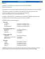
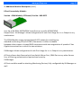
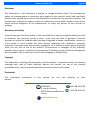
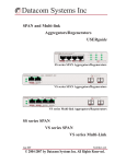
www.profitap.com
User Manual
XX-32G
CUSTOMER SUPPORT INFORMATION
To order or for a technical information support:
Phone: +33 3 88 10 18 30 or
Fax: +33 3 88 10 18 35
COMCRAFT
2, rue de la Mairie
67203 Oberschaeffolsheim - France
Website: www.profitap.com
E-mail: [email protected]
page 1
www.profitap.com
V2.0 © Comcraft 2011
* all items are subject of change without notice *
page 2
www.profitap.com
You purchased a XX-series solution.
Thank you for the confidence placed in our products.
page 3
www.profitap.com
page 4
About Us
COMCRAFT is the leading manufacturer of professional LAN & WAN
Monitoring Equipment.
Our products are of the highest quality, better featured and build with the latest technology.
The confidence placed in our products is the reward for many years listening to our
customer’s needs and expectations, improving technology and
service, and offering an ever-expanding product line.
Founded in 1984 COMCRAFT is headquartered in Strasbourg, FRANCE and present in the
worldwide market through leading partners and reseller networks
COMCRAFT offers a complete range of:
♦
♦
♦
♦
XX-Series
XX-32Glite
XX-32G
XX-32Gportable
Network Consolidation Tools
Network Consolidation Tools
Network Consolidation Tools
Passive Optical Fiber Taps
Single Port
Dual Port
Quad Port
Rack Mount/Portable
Rack Mount
Rack Mount
Passive Copper Taps
Single Port
High Density 4 to 20 ports
Regeneration
Rack Mount/Portable
Rack Mount
Rack Mount
Wan Taps
T1/E1
E3/DS3
RS422/X21
HSSI/T3
Rack Mount/Portable
Rack Mount/Portable
Rack Mount/Portable
Rack Mount/Portable
COMCRAFT’s objective is to become your premier solution provider, offering you the best
product support and manufacturing products with the latest network technology.
www.profitap.com
Table of Contents
1.
General Information
Overview System and Hardware
2.
XX-32G Visual Description
Front & Backview
View with Connectivity Module
3.
Connectivity Module Description
Version Copper In-Line
Version SPAN Module
Version SPAN Module, SFP based
Option Slot - passive FiberTAP for 1GbE / 10GbE Networks
4.
Unpacking & Installation
Physical Installation
Verifying installed Module / Install Connectivity Module
Installing SFP and SFP+ Connectors
5.
Connecting to Network and Appliances
Connect to SPAN Ports
Connect Copper In-Line Links
Connecting In-Line Fiber Links
Connecting Monitoring Appliances
Connection Samples
6.
Powering On XX-32G
Powering Up
Systemstatus Indicators at Frontpanel
7.
Basic Network Settings
Getting started
8.
Retrieving Factory Defaults
9.
Specifications
10. Disclaimer
page 5
www.profitap.com
page 6
General Information
Overview System
XX-32G
The XX-32G is a up to date, versatile solution, designed for aggregation, filtering and routing
of multiple In-Line and/or Span inputs,
either 10GbE or 1GbE datastreams, for Monitoring & Analysis Tools by 1GbE
or 10GbE Monitoring tools.
XX-Manager
The essential part of XX-32G is XX-Manager, an integrated application for configuring Aggregation, Filtering & Routing and Definition of any port to be of used for either Input or Output
operations.
See Software Manual for how to use.
Overview Hardware
The unit holds four fixed 1GbE and two fixed 10GbE ports, the
swappable connectivity module providing eight additional 1GbE ports for copper or fiber as
In-Line or Span ports.
One additional slot offers mounting a Fiber TAP for up to four failsafe Fiber In-Line links, feeding SFP Span connectivity module ports.:
TAP section
Connectivity
section
10G
Aggregation
Sample view Hardware : XX-32G unit + Copper In-Line connectivity module + Quad Fiber TAP
www.profitap.com
page 7
2. Visual Description
Rackmount brackets
Front View
Expansion Slot
Swappable Slot 1
4 fixed SFP (1Gb) ports
2 fixed SFP + (10Gb) ports
Link/Activity/Power LEDs
Information Field
Back view
Redundant , international (110-240V) powersupplies *
Cooling: two speed controlled fans in
demountable/replaceable unit.
RS422 Management
Port
RJ45 Management
Port
* and/or optional 48VDC (telco)
www.profitap.com
2. Front view with Connectivity Unit
Copper In-Line Module
Copper Span Module
SFP based (SPAN) Module
All modules with speed/link/activity
Sample view with inserted 8 Ports Connectivity Module (here SFP-Module)
page 8
www.profitap.com
page 9
3. Additional Module Description
8 Port Connectivity Module:
Version : Copper In-Line, Part No. : XXS-4CIL
Use: Up to four (4) true In-Line TAPs for 10/100/1GbE UTP
The Copper In-Line Module comes equipped with eight RJ45 Connectors. Once connected
links are failsafe and attached segments will never be
interrupted, even if the XX-32G is not powered due any reason.
The configuration (speed, full or half duplex) on each connected Network Link is initialized by
the data flow passing the connected link automatically.
In addition, LED-based signalling displays in real time the speed of each port, its activity and
indicates any failure during link detection.
Version : Copper SPAN Module, Part No. : XXS-8CSP
Use: Up to 8x SPAN 10/100/1GbE Input Ports or up to 8x 10/100/1GbE
Output Ports. XX-Manager (see Software manual) allows configuration of each Port Usage for
In- or Output in any combination.
The Copper SPAN Module is equipped with 8x RJ45 Connectors.
All Ports allow a data flow analysis from Switch Mirror Port, SPAN Port or any other Source
line, all filtering and extraction can be set by XX-Manager (see Software Manual for how to
configure).
All Ports could be used for attaching Monitoring Devices, fully configurable by XX-Manager as
well.
Each port is tri-speed (10/100/1GbE) and will automatically detected and configured while
connected to a switch or monitoring output line.
In addition, LED-based signals display in real time the speed of each port, its activity and
inform of any failure during link detection.
www.profitap.com
page 10
3. Additional Module Description (cont’)
8 Port Connectivity Module:
Version : SPAN Module, SFP based, Part No.: XXS-8SFP
Use: Up to 8x SPAN 10/100/1GbE Input Ports or up to 8x 10/100/1GbE
Output Ports. XX-Manager allows configuration of each Port Usage for In- or Output in any
combination.
The SPAN Module comes equipped with 8 SFP sockets for installing any
standard conforming SFP (mini-GBIC) Connectors. It offers to choose
between either copper tri-speed RJ45 transceivers with auto-negotiation of speed or Fiber
Gigabit transceivers or a mix of the two solutions.
XX-Manager allows configuration of each Port Usage for In- or Output in any combination.
All Ports allow a data flow analysis from Switch Mirror Port, SPAN Port or any other Source
line, all filtering and extraction required can be set by
XX-Manager.
All Ports could be used for attaching Monitoring Devices, fully configurable by XX-Manager as
well.
www.profitap.com
page 11
3. Option Slot: Passive Fiber TAP
This slot is for a In-Line passive FiberTAP solution.
Quad Fiber TAP
in Alternate:
Single Fiber TAP
Use: The sets of passive couplers guarantee that XX-32G will never cause a point of failure to
any fiber network segment. Up to 4 passive
In-Line Splits for further use can be realized.
There are two versions of passive FiberTAPs fitting into the XX-32G, both versions of the passive FiberTAP can be used in combination with any 8 Port Connectivity module, depending on
1GbE or 10GbE on fixed Ports as well:
Sample : view with F4L passive FiberTAP
Sample : view with F1RL passive FiberTAP
www.profitap.com
page 12
3. Option Slot: Passive Fiber TAP (cont’)
Fitting to the local Fiber Network‘ specifications (MultiMode, SingleMode, Split Ratio) the
Monitor Outputs of the passive TAP can used both further for being the Intakes to either
1GbE SPAN Ports of the Connectivity Module or to either fixed 1GbE or 10GbE Ports at XX32G.
Please refer to the Manual and/or Datasheet of the correspondend FiberTAP for proper specification and operation within your 1GbE or 10GbE Fiber Network.
Sample : using F1RL passive FiberTAP to SPAN Intake as defined at XX-32G:
Network
Device A
A
Network
Device B
B
Directional Monitoring Traffic
1GbE (or 10GbE)
Sample : using F4L passive FiberTAP to SPAN Intake XX32G + XXS-8SFP 8 Port SFP (SPAN) Module:
Network
Device A
A
B
Network
Device B
Directional Monitoring Traffic
1GbE (or 10GbE)
passive In-Line FiberTAP Specifications
(For complete Information refer to brochure of specific FiberTAP):
Base
Product
Fibre
Type
Split
Ratio
50 *
F1RL
F4L
-
E
U
S
Z
60 *
-
70 *
80 *
90 *
Sample:
F1RL-E-70 = single Port, LC Connectors,
MultiMode 50u Core and 70:30 Split
www.profitap.com
page 13
4. Unpacking and Installation
Unpack careful all items and retain packing material for later use.
XX-32G is shipped with the following items:
•
•
•
•
•
XX Main Unit
Swappable Module(s) (if purchased)
1x Power Cord & 1x Cat5 & 1x RS232 Cable, 2m ea.
Rackmount Set (not XX-32Gportable)
Quick Start Guide
Please contact your supplier if any part is missing or damaged.
Desktop or Rackmount of XX-32G
XX-32G can be placed on shelf or on desktop.
If required, XX-32G may be mounted into a 19” rack:
a) Slide the main chassis into the desired rack location
b) Secure the chassis using the supplied screws
c) Make sure the rack is grounded properly
For optimal & balanced thermal conditions the TAP and Module slot must be closed by filler strips in
case no TAP or Module is installed .
Connecting Power
Make sure to connect the redundant powersupplies to two separate,
independent power sources using the supplied power leads.
Make sure the mains powersources are grounded properly.
Note : If powercords are connected to mains the unit will power up. It is recommended to continue in
unplugged condition and follow this manual up to Chapter 6 at first installation process before powering
up.
Mounting Connectivity Module
If the XX-32G is already equipped with a connectivity module check the
module for proper mounting prior of powering on the device.
If the Connectivity Module needs to be inserted first, follow this steps:
a) Remove the cover plate on the front by unscrewing the thumbscrews.
b) Slide in the Connectivity Module with the circuit board riding in the rails.
c) Push the Module firmly in its final position and the bezel is smoothly in match with the Frontpanel.
d) Secure the Module with the thumbscrews.
Note : This Module(s) are swappable - you may exchange the module at any time under power, being
aware of data loss during the change.
www.profitap.com
page 14
4. Unpacking and Installation (cont.)
Installing SFP and SFP+ Connectors
No SFP or XFP are included unless ordered separately via your supplier.
Any SFP based Network Port at XX-32G must be equipped with a
standard Module to match the local requirements.
Any SFP+ based Monitor Port at XX-32G must be equipped with a
standard Module to match the local requirements.
Slide in the modules careful until it clicks and verify the proper seat.
Verifying the Installation
XX-32G’ functions depend on settings by the embedded Management
Application. The optimum configuration depends on kind of connections and equipment
being used for individual purposes.
You may continue with attaching the Network Links and/or the Monitoring appliances
according to requirements with or without powering on
XX-32G.
Attaching Links and Monitoring Appliances in operational mode (powered on) is assisted by
indicators at the front panel and at the connectivity
module.
Location of Indicators :
Systemstatus
Link Activity/Speed
Power
Information
Field
If powered up now, check the LED Indicators for proper power conditions and with the Link
LEDs on each connected port that the links are connected well and datatraffic is present.
It is recommended to continue in unplugged condition and follow this
manual up to Chapter 6 at first installation process before powering up.
www.profitap.com
page 15
5. Connecting to Network and Appliances
Connecting SPAN Ports to XX-32G (fixed Ports or Module Ports)
a)
b)
Attach to any fixed SPAN Ports or to SPAN Ports of installed
Connectivity Module by appropriated cable.
Apply the other end of cable to any SPAN Port of any switch or any other source of traffic.
(Refer to next page in case any of fixed or SPAN Module Port should be used for Monitoring)
Please Note there are 2 different Modules: either SFP based, Part No.: XXS-8SFP or RJ45, Part
No. : XXS-8CSPs both offer usage either as Intakes or
Monitor Outputs.
Connecting In-Line to a Network
Using the In-Line Connectivity Module (Copper In-Line Module XXS-4CIL)
This Module is arranged to four (4) pairs of RJ45 connectors, sequencely numbered 1-2, 3-4,
5-6 and 7-8:
In-Line Module
Front View:
2
4
6
1
3
5
8
7
a)
Attach first In-Line pair to, i.e., Port 1 at Connectivity Module a
appropriated cable as Inbound “A” from the Network Link being tapped.
b)
Continue by the corresponding port “B” from the Connectivity Module by a straight
cable to Port 2 to wire out the monitored
Network link.
c)
Continue with pair 3-4, 5-6, 7-8 being further pairs of In-Line
functions to be used.
Note : Any other pair for use to begin with is valid - there is no order for a primary use of
those In-Line Taps
www.profitap.com
page 16
5. Connecting to Network and Appliances
Using the passive FiberTAP in Option slot (F1RL or multiple F4L):
Please select the required Fiber TAPs Specifications as needed following the informations
being provided for the FiberTap F1RL and F4L.
(see section 3 - Option Slot for overview)
Sample : using F4L passive FiberTAP to SPAN Intake XX32G + XXS-8SFP 8 Port SFP (SPAN) Module:
Network
Device A
B
Network
Device B
a)
b)
c)
Refer to Connectivity samples on next
pages for more 1GbE or 10GbE operations
A
Attach to Network Port “A” of the FiberTAP a appropriated cable as Inbound “A” from the
network Link being tapped.
Apply to Network Port “B” a appropriated cable as to wire out the monitored network
link.
Connect to the Monitor “AB” of the FiberTAP 2 single Fiber cables to two SPAN Ports,
either to the fixed at the Connectivity
Module.
Note : Using the F4L allows to tap into 4 separate Fiber Network Links and may end up in
using 8 SPAN Ports
Connecting Monitoring Devices to XX-32G
XX-32G’ functions depend on the configuration used .
Any previously described “SPAN” Ports for use as Intake may be set for being an Output for
Monitoring Appliances in alternate.
To select either fixed or Module based SPAN Ports or 10GbE SFP+ Ports for attaching such
devices is fully controlled by the Management.
Any combination of In- or Output with or without filtering inbound or outbound traffic or
further aggregation of any traffic and replication can be set as required. (see Software Manual
for how to use)
www.profitap.com
page 17
5. Connecting to Network and Appliances (Samples)
XX-32G:
Set for aggregating four Input Lines (SPANs) at 1GbE by fixed ports, interfaced by SFP (Copper
or Fiber) for Output set to first 10GbE SFP+ Port:
4x 1GbE SPAN
Monitor Device
XX-32G and In-Line Connectivity Modul:
Set for aggregating 4x 1GbE In-Line Tapping plus additional 2x 1GbE SPAN ( fixed Ports) for
Output set to first 10GbE SFP+ Port:
4x 1GbE In-Line
Monitor Device
2x 1GbE SPAN
XX-32G and SPAN Connectivity Module (Copper or SFP):
Set for aggregating 8x 1GbE SPAN plus additional 4x 1GbE SPAN (fixed Ports) for Output set to
both 10GbE SFP+ Ports:
Monitor Device A
Monitor Device B
12x 1GbE SPAN
www.profitap.com
page 18
5. Connecting to Network and Appliances (Samples) (cont’)
XX-32G and SPAN Connectivity Module (Copper or SFP):
Set for aggregating 10x 1GbE SPAN Input ( 7x by Connectivity Module plus additional 3x 1GbE
SPAN by fixed Ports for Output set to both 10GbE SFP+ and 2x 1GbE Ports at Connectivity Module and fixed Ports:
10x 1GbE SPAN
Monitor Device A
Monitor Device B
Monitor Device C
Monitor Device D
XX-32G and FiberTAP via SPAN Connectivity Module (SFP):
Set for aggregating 9x 1GbE SPAN Input ( 7x by Connectivity Module plus additional 2x 1GbE
SPAN by fixed Ports for Output set to first 10GbE SFP+ and 3x 1GbE Ports at Connectivity Module and fixed Ports:
Network A
Network B
Monitor A B
7x 1GbE SPANbE
Monitor Device A
Monitor Device B
Monitor Device C
Monitor Device D
Note : The passive In-Line Fiber TAP Monitor A/B outputs are connected further to 2x 1GbE
SPAN Ports of XX-32G. All SPAN Intakes can be Copper or Fiber SFP‘s in any mix.
The shown Quad Fiber TAP allow 4 passive Fiber In-Line Tappings
connected further to any defined SPAN Input Port at XX-32G.
www.profitap.com
page 19
5. Connecting to Network and Appliances (Samples) (cont’)
XX-32G and 10GbE SPAN Monitoring:
Set for filtering and strapping down 2x 10GbE SPAN Input for various Outputs at 1GbE (at fixed Ports or Connectivity Module Ports).
Additional 1GbE Span Inputs may be processed and filtered and/or routed to same or dedicated Outputs as well:
2x 10GbE SPAN
Monitor Device A
Monitor Device B
Monitor Device C
Monitor Device D
XX-32G and 10GbE failsafe Fiber In-Line Monitoring:
Set for filtering & routing 1x 10GbE In-Line via passive FiberTAP Option to SPAN Input for various Outputs at 10GbE and/or 1GbE Outputs by fixed Ports:
10GbE Network
Passive In-Line
to Monitor Out at 10G (SFP+) Input
(up to 4x) directional 2x1GbE Monitor 2x Monitor
of 10GbE Link directional 10GbE
www.profitap.com
page 20
6. Powering on XX-32G
Assuming all necessary precautions while physical connections have been proceeded the unit
can be powered on now :
The System does not provide a main power switch, XX-32G powers up if one of redundant
powersupplies is being connected to mains power.
The use of both powersupplies is recommended to achieve a maximum failsafe operation at
any time.
Please remember the connectivity module are swappable - you may exchange or add a
module at any time under power, but be aware of data loss during the exchange.
There are 2 vertical groups
of LEDs:
4x Systemstatus
2x Power
Systemstatus Power
If power is connected refer to the System Status and Power indicators
during the initialization process :
LED # 2, 3 + 4 off to orange
LED PWR 1 on : connected to mains and active
LED PWR 2 on : connected to mains and active
LED #2 off/turns constant orange: Device starting in progress
LED #1 constant green: All components active
The XX-32G initialisation takes appr. 40 seconds. If ready, the
display will change to indicate the normal Operation Mode :
LED # 2, 3 + 4 green
LED PWR 1 on: active
LED PWR 2 on: active
LED #1 flashing green: normal Operation
www.profitap.com
page 21
6. Powering on XX-32G (cont’)
The presence of redundant power is displayed by 2 separated Power Indicators (LEDs). If
constant on, the Powersupply is active. If one LED is off, this could either indicate only a single
Powersupply is in use or the second
powersupply is not in function.
(There is no order for using powersupplies No. 1 or 2 at single
mains operation - any for a primary use is valid)
Verify proper operation of both Powersupplies by connecting the second unit to mains to see
LED is reporting the functional status for Redundancy at normal Operation in case it is
required.
Indications during Update Process being performed:
LED #1, 2, 3 + 4 steady orange for ~20s after reboot
LED PWR 1 on: active
LED PWR 2 on: active
For all events and indications always check at the Mamagement Application Status page for
further information (see Software Manual for how to use)
www.profitap.com
page 22
7. Basic Network Configuration
Getting started (cont’)
As main part of XX-32G the XX-Manager - a GUI-driven Configuration- is controlling the SetUp
for Aggregation, Filtering & Routing and gives control over 1GbE & 10GbE Network Traffic for
Monitoring.
Multiple Filter rules per Port in any combination for various Routing and Filtering, Duplication
or Replication and more options can be configured for adaption to all kind of analysis.
An integrated archive gives quick access to establish filters scenarios on the fly or allow
storage of previously used filtersets to meet new or standard requirements.
To connect with the Management locate the Management Ports on
the backside of XX-32G - there are 2 connections available:
RS422
Management
RJ45 Management Port
Two 2 ways to access:
1.
Ethernet (up to 1Gbps) http, https, SSH
Default Network setup : IP 192.168.0.2 / 255.0.0.0
Security : https (256bit) : SSL 1024bit certificate is pre-installed
2.
Serial RS232 console
This is the fall-back mode in case any restore of factory defaults is required.
(see chapter 8. Retrieving Factory Defaults)
Connection setup : 115200 baud, 8bit, No parity, 1 bit stop
www.profitap.com
page 23
7. Basic Network Configuration cont’)
Getting started (cont’)
Continue with connecting XX-32G to your Network or use the a cross cable to connect your
Computer to XX-32G or to same physical Network.
Connect to XX-32G by typing in the default IP-adress 192.168.0.2 in any browser on your local
PC.
Overide any browser dependent alert to continue. (Access by default with forcing browser to
bypass with a self generated certificate is possible time)
XX-32G will prompt with its Status Page:
At this stage please continue with the
Software Manual as provided online.
After Log In a extended Status page is displayed, offering the option of downloading the
hardware and the software manual:
www.profitap.com
page 24
7. Basic Network Configuration cont’)
Getting started (cont’)
Secure Access - SSL/HTTPS:
A SSL certificate is pre-installed on the XX-32G, a new certificate can be generated or
imported. Refer to Software Manual for generating/importing a certificate.
DHCP :
Hostname - If DHCP is enabled, XX-32G is accessible with its hostname :
http://XX-32G
(The Hostname can be change, please refer to the Software Manual)
If DHCP is disabled the XX-32G can be accessed by its IP address :
http://192.168.0.2
Note :
For security, the Login and Passwords are being send in https mode, even if XX-Manager is
still or remains to be in http state.
www.profitap.com
page 25
8. Retrieving Factory Defaults
In case the System Configuration has been corrupted or main parameters have been changed
without notice due any reason XX-32G can be reset by connecting via TTY (Linux) or any other
terminal software (e.g TeraTerm on Windows) to the RS232 Management Port.
Refer to Chapter 7 , -Getting started- for physical connecting a Telnet- based Terminal (or PC
Emulation) to XX-32G.
Once connected, a commandline-based Menu will allow to select the
functions for restoring partial or complete factory defaults parameters of the system.
Warning : All stored Filter Set are deleted and the factory default library is restored.
9. Additional Information
Technical and electrical features
Specifications:
Rigid 1U metal enclosure, black oven painted
International, Redundant, AC power (100-240V/50-60Hz), 60W
Optional : Redundant –48Volt Telco powering
Cooling : Two temperature controlled fans
Operating : 0°C to 50°C / Storage : -20°C to 90°C
Humidity : 10% to 90%, none condensing
Weight & Size:
19“ Main unit 44x480x260 mm (HxWxD), Weight : 5 kgs
Approvals:
Made in EU
www.profitap.com
page 26
Disclaimer
The information in this document is subject to change without notice. The manufacturer
makes no representations or warranties with respect to the contents hereof and specifically
disclaims any implied warranties of merchantability or fitness for any particular purpose. The
manufacturer reserves the right to revise this publication and to make changes in the content
hereof without obligation of the manufacturer to notify any person of such revision or
changes.
Warranty and Liability
Comcraft warrants that this product is free from defects in material and workmanship at time
of shipment. The warranty period is three years from the date of purchase. Comcraft
assumes no liability for products that have been subjected to abuse, modification, misuse, or
if the model or serial number has been altered, tampered with, defaced or removed.
Comcraft is not liable under any contract, negligence, strict liability or other legal or equitable
theory for any loss of use of the product, inconvenience or damages of any character,
whether direct, special, incidental or consequential (including, but not limited to, damages for
loss of goodwill, loss of revenue or profit, work stoppage or malfunction)
Copyright
This publication, including all photographs and illustrations, is protected under international
copyright laws, with all rights reserved. Neither this manual, nor any of the material
contained herein, may be reproduced without written consent of the author
Trademarks
The trademarks
owners.
mentioned
in
this
manual
are
the
sole
COMCRAFT
2, rue de la Mairie
67203 Oberschaeffolsheim
France
www.profitap.com
property
of
their
+33 3 88 10 18 30
+33 3 88 10 18 35