1
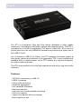
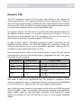
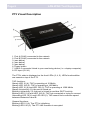
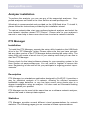
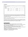
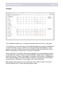
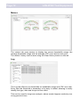
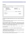
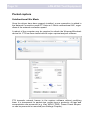
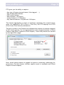
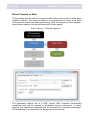
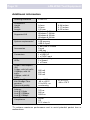
WWW.PROFITAP.COM
PT3
User’s manual
GigaBit Ethernet Aggregation Tool
Page 2
LAN-WAN Test Equipment
Thank you for purchasing the PT3.
Package contents:
- 1* PT3 main unit
- 1* USB key containing drivers and software
- 1* USB 3.0 cable
- 1* User’s manual
www.profitap.com
Page 3
Table of contents
General Information……………………………………………..
Network TAP……..……………………………………………….
PT3 Visual Description………………………………………….
Driver Installation………………………………………………..
Analyzer installation…………………………………………….
PT3 Manager……………………...………………………………
Installation
Description
Statistics
Counters
Graphs
Meters
Log
Features
Packet capture……………………………………………………
Unidirectional Nic Mode
Direct Capture to Disk
Additional Information………………………………………….
4
5
6
7
9
9
9
9
9
10
11
12
12
13
14
14
16
18
Page 4
LAN-WAN Test Equipment
The PT3 is a handheld, Plug and Play device dedicated to inline gigabit
monitoring. It facilitates in-field traffic capture and troubleshooting. The PT3 is
equivalent to a 10/100/1G aggregator TAP and a 2 Gbit/s NIC. All-in-one in a
pocket-sized box, the only additional hardware required being a laptop with a
free USB 3.0 port.
As it is based on USB 3.0 (5 Gbit/s), the PT3 manages full-duplex gigabit at
wire speed, without the bottleneck of an aggregator TAP. It also surpasses all
standard NICs in capture mode, as the PT3 catches any tag and encapsulation without altering frames.
The PT3 is the perfect tool for the field engineer as well as for long-term traffic
collection.
Features
- 10/100/1G monitoring on USB 3.0
- USB 3.0 powered
- Failure safe monitoring
- Hardware aggregation
- 8 ns hardware timestamp
- Real time statistics
- Low level error and bandwidth monitoring
- CRC error capture
- Capture any packet with any analyzer
- Direct capture to disk
www.profitap.com
Page 5
Network TAP
The PT3 integrated network TAP provides safe access to the network for
monitoring purposes. It is a passive monitoring device, meaning it is undetectable, the original traffic staying unaltered and no extra packets being inserted.
As most of the TAP’s functions are performed by dedicated hardware circuits,
it is much more reliable and error proof than SPAN ports.
In a gigabit network, the TAP has to negotiate with both attached devices for
the highest common speed. If no common speed can be found, or if one of
the devices is disconnected, the TAP propagates the error to the other attached device, allowing a redundant path to be activated.
In case of power failure, it activates its bypass circuits, connecting the two
attached devices directly. The ProfiTAP Gigabit Tap integrates a high performance fast failover circuit and a proprietary algorithm, reducing the unavailability of the network path down to 30ms.
Note: the fast failover relies on the network setup. In case the fast failover
cannot perform, the two end devices have to renegotiate the link. This operation takes about 2 seconds.
End Device 1
End Device 2
DTE
DCE
Straight Through and Crossover
1 Cable Types
DCE
DTE
Straight Through and Crossover
DCE
DCE
DTE
DTE
Straight Through and Straight
Through
Straight Through and Straight
Through
Note: The user should verify that the two end devices only connect together
with either a cable or an unpowered Tap. The straight or crossover cables
must be employed in case of end devices that do not support Auto MDI/MDIX
(i.e. Auto Crossover). Experienced users can bypass this procedure.
Note: Although some vendors recommend the use of the non-IEEE compliant
“Forced Gigabit” mode, we strongly recommend activating auto-negotiation
when Gigabit speed is required. More generally, auto-negotiation should
always be enabled on both end devices in order to avoid duplex mismatch
issues.
Page 6
LAN-WAN Test Equipment
PT3 Visual Description
1. Port A (RJ45) connected to the network
2. Port B (RJ45) connected to the network
3. (see below)
4. (see below)
5. (see below)
6. Power button
7. USB 3.0 connector linked to your monitoring device (i.e. a laptop computer)
8. DC input (5V/1A)
The PT3’s state is displayed on the front LEDs (3, 4, 5). LEDs functionalities
are named on top of the PT3.
TAP functions:
Steady LED 10 (4): TAP is operating at 10 Mbit/s
Steady LED 100 (5): TAP is operating at 100 Mbit/s
Steady LED 10 (4) and LED 100 (5): TAP is operating at 1000 Mbit/s
Steady Link/activity (3): the port is linked up
Blinking Link/activity (3): the port is linked up and has RX/TX activity
Blinking LED 10 (4) and LED 100 (5): TAP not connected or trying to connect
Alternating LED 10 (4) and LED 100 (5): TAP cannot find a common speed
between Networks A and B
General functions:
Blinking LED 10 (4): The PT3 is initializing
Blinking LED 100 (5): The PT3 HW firmware is corrupted
www.profitap.com
Page 7
Driver Installation
Drivers are available for Windows 7 32/64 bits and Windows 8 32/64 bits.
To install the PT3 drivers, execute the setup utility located on the USB flash
drive in the “PT3 Manager” folder. Please make sure that you have uninstalled any older version of PT3 Manager before starting the setup utility.
Connect the PT3 on a free USB 3.0 port and the drivers should install automatically. For a manual installation, the drivers can be found in the default
installation folder “C:\Program Files (x86)\Profitap\PT3 Manager\Driver\PT3”.
A reboot of the computer may be required in order to refresh the Winpcap/
Wireshark device list.
Please check for the latest driver release for your operating system in the
User Section at www.profitap.com. You will need to register to access this
area. Registering is free and will let you participate in ongoing product improvements.
Page 8
LAN-WAN Test Equipment
www.profitap.com
Page 9
Analyzer installation
To perform the analysis, you can use any of the supported analyzers. Supported analyzers are listed in the User Section at www.profitap.com.
Wireshark is recommended and provided on the USB flash drive. To install it,
please follow the instructions provided by the installation wizard.
To capture network data, start your preferred network analyzer and select the
new network interface named “PT3 Device”. Please refer to your analyzer’s
manual or user help to know more about how to select a network interface.
PT3 Manager
Installation
To install the PT3 Manager, execute the setup utility located on the USB flash
drive in the “PT3 Manager” folder. Please make sure that you have uninstalled any older version of the PT3 Manager before starting the setup utility. The
setup utility will create a launch icon in your startup menu that you can use to
start the PT3 Manager.
Please check for the latest software release for your operating system in the
User Section at www.profitap.com. You will need to register to access this
area. Registering is free and will let you participate in ongoing product improvements.
Description
PT3 Manager is a standalone application designed by ProfiTAP. It provides a
way for statistical analysis of a network, allowing for efficient excessive
bandwidth usage detection, or any low layer errors using charts prior to a
deeper investigation using an analyzer. It is also used as a firmware flashing
utility to update your product.
PT3 Manager can be used at the same time as a software network analyzer,
without the need to interrupt data capture.
Statistics
PT3 Manager provides several different visual representations for network
statistics. The following pages give an overview of these representations.
Page 10
LAN-WAN Test Equipment
Counters
In the Counters tab are listed every counter embedded in the PT3 for both
network ports. The counters are 64 bits hardware counters, they are cleared
at hardware startup only.
Statistics can be reset individually for each port or for the two ports at the
same time using the buttons on the left.
Clearing the counters using the buttons does not clear the hardware counters,
but stores all counters in reference counter. Then, the displayed counters are
result of the formula (hardware counter - reference counter).
Counters description:
“size < 64 bytes”: the CRC valid frames with a size under 64 bytes.
“64< size < 1518”: the CRC valid frames with a size over or equal to 64 bytes
and under or equal to 1518 bytes.
“size > 1518 bytes”: the CRC valid frames with a size over 1518 bytes.
“Collisions”: the CRC error frames with a size under 64 bytes.
“CRC Errors“: the CRC error frames with a size over or equal to 64 bytes and
under or equal to 1518 bytes.
“Jabbers”: the CRC errors frames with a size over 1518 bytes.
“Valid frames” : the CRC valid frames of any size.
“Invalid frames” : the CRC error frames of any size.
“Total bytes” : the valid frame bytes.
www.profitap.com
Page 11
Graphs
The Graphs tab allows you to inspect statistical data over time, using plots.
For each port, you can plot any of the statistical data by using the checkboxes
on the left. Once a box is checked, the corresponding data appears on the
graph on the right. Refresh rate can be selected using the drop down list on
the left, allowing you to plot up to 10 hours of statistics.
When “packet/s” is selected, each series displays the corresponding number
of packets per second, except for the bandwidth usage which is displayed in
bytes per second. When “percentage” is selected, each series is displayed in
term of percentage of the total number of packets, except for the bandwidth
usage which is displayed in percentage of the total bandwidth.
Both graphs history can be reset using the Clear History button on the left.
Disconnecting the PT3 also reset the graphs’ data.
Page 12
LAN-WAN Test Equipment
Meters
The meters tab uses meters to display the current bandwidth usage, the
average bandwidth usage and the average CRC error rate for each port.
The meters’ history can be reset using the Clear History button on the left.
Log
The Log tab offers to set thresholds for bandwidth usage and CRC error rate.
Every time the threshold is exceeded, a log entry is added, allowing to easily
identify the type, date and the port of the event.
This can be used for long term analysis, where events happen randomly over
a long period of time.
www.profitap.com
Page 13
Features
The Features tab regroups information about the driver and firmware version,
port status, the firmware update utility and a way to enable or disable PT3
features.
To update the PT3 firmware, use the browse button to select the firmware file
and press the Flash Firmware button.
The corresponding firmware update will begin. You cannot use the PT3
Manager when the update is in progress. The update process may take
several minutes to complete. Once it is done, please unplug and replug the
PT3 device to use the new firmware. Please do not unplug the USB port nor
shut down your computer during the update process.
You can download the latest firmware from the User Section at
www.profitap.com.
On the same screen, you can enable or disable the following features:
- Transmit CRC Errors: if checked, the PT3 will not filter out network packets
with CRC errors like a normal NIC would.
- Keep CRC32: removes the CRC32 information (32-bit Frame Check Sequence) located at the end of the packets.
Note: if both options “Transmit CRC Errors” and “Keep CRC32” are enabled,
all the erroneous packets will be treated as fair ones.
Page 14
LAN-WAN Test Equipment
Packet capture
Unidirectional Nic Mode
Once the drivers have been properly installed, a new connection is added in
the Network Connection panel.PT3 acts as 2 Gbit/s unidirectional NIC, regardless of the network connection speed.
A reboot of the computer may be required to refresh the Winpcap/Wireshark
device list. PT3 has been tested with all major capture/analyzer software.
PT3 transmits network frames to the capture software without modifying
them. It is transparent for packet size, packet type or protocols. All tags and
encapsulation are preserved (e.g. Vlan, MPLS, GRE). Frame Check Sequence can be preserved or removed (see Settings Chapter).
www.profitap.com
Page 15
PT3 gives you the ability to capture:
- Any type of frames (pause frames, Vlan tagged, …),
- Any encapsulated frames,
- CRC errors frames,
- Short frames (< 64 bytes),
- Jumbo frames (> 1518 bytes),
- Any frames between 10 bytes and 10 Kbytes,
The frames aggregation is done in hardware respecting the original frame
order. As opposed to FIFO (First In, First Out), the PT3 employs an FCFS
(First Come, First Served) mechanism.
The drop counter in the Feature tab indicates the number of packets dropped
in NIC mode capture. It’s not representative of the dropped packets in Direct
Capture (see Direct Capture to Disk chapter). These drop events are caused
by too high CPU usage.
Note: small packet capture at gigabit full speed is extremely challenging for
processors. For that reason, another capture mode is available (see Direct
Capture to Disk chapter).
Page 16
LAN-WAN Test Equipment
Direct Capture to Disk
PT3 provides with the option to capture traffic without the need of a third-party
capture software. This mode of capture is accomplished on driver level, prior
to all network stacks and frame processing. With the support of direct capture,
small packet capture can be performed at full wire speed.
The generated capture file is in ERF format. ERF supports nanosecond
timestamp and can be opened in Wireshark without conversion. In direct
capture, the frames are stamped with an accurate 8ns hardware timestamp.
The timestamp is computed at the beginning of each frame.
www.profitap.com
Page 17
PT3 Manager – Direct Capture setup:
Output Capture File: specify the name and location of the capture file.
Memory Cache Size: specify the amount of RAM to be used as capture cache
(10MB – maximum available).
Maximum Capture File Size: specify the maximum size for the capture file.
Start Capture: when capture isn’t running, starts the capture with the specified
parameters.
Stop Capture: when capture is running, stops the capture and releases the
capture file.
Current Cache Usage: indicates the usage level of the RAM cache.
Written to File: indicates the amount of data written in the Output Capture
File.
Dropped: indicates the amount of data dropped during the Direct Capture.
Note: the amount of dropped data depends on the data storage throughput
and the amount of RAM cache. Disk arrays or SSDs may drastically improve
capture performance.
Page 18
LAN-WAN Test Equipment
Additional information
Ordering reference
Dimensions
Height
Width
Length
Supported OS
System requirements*
Accessories
Connectors
LEDs
Power Consumption
(5V)
1Gbps, with full traffic
100Mbps, with full
traffic
10Mbps, with full
traffic
Operating Temperature Storage Temperature
Relative humidity
Maximum Network
Latency
Link @ 1Gpbs
Link @ 100Mbps
Link @ 10Mbps
Compliance
C1AP-1G
24 mm
0.94 inches
55 mm
2.17 inches
102 mm
4.02 inches
Windows 7 32 bits
Windows 7 64 bits
Windows 8 32 bits
Windows 8 64 bits
Dual Core Processor
1GB memory
USB 3.0 port
1.8m USB 3.0 cable
Pouch
USB key
2 x RJ45 8 pins
1 x USB 3.0
1 x 5VDC input
2 x Link activity
2 x Speed
1 x Power
600 mA
450 mA
520 mA
0 to +50°C
-40 to +80°C
10 to 95%, no
condensing
32 to 122°F
-40 to 176°F
370 ns
660 ns
6600 ns
RoHS
CE
FCC class A
*To achieve maximum performance and to avoid potential packet loss or
malfunctions.
www.profitap.com
Page 19
Disclaimer
The information in this document is subject to change without notice. The manufacturer makes no representations or warranties with respect to the contents
hereof and specifically disclaims any implied warranties of merchantability or
fitness for any particular purpose. The manufacturer reserves the right to revise
this publication and to make changes in the content hereof without obligation of
the manufacturer to notify any person of such revision or changes.
Warranty and Liability
Comcraft warrants that this product is free from defects in material and workmanship at time of shipment. The warranty period is two years from the date of
purchase. Comcraft assumes no liability for products that have been subjected to
abuse, modification, misuse, or if the model or serial number has been altered,
tampered with, defaced or removed. Comcraft is not liable under any contract,
negligence, strict liability or other legal or equitable theory for any loss of use of
the product, inconvenience or damages of any character, whether direct, special,
incidental or consequential (including, but not limited to, damages for loss of
goodwill, loss of revenue or profit, work stoppage or malfunction).
Copyright
This publication, including all photographs and illustrations is protected under
international copyright laws with all rights reserved. Neither this manual, nor any
of the material contained herein, may be reproduced without written consent of
the author.
Trademarks
The trademarks mentioned in this manual are the sole property of their owners.
v0.9
©2013, Comcraft
CUSTOMER SUPPORT INFORMATION
For technical information support:
Phone : +33 388 101830
Fax : +33 388 101835
Mail order : COMCRAFT
17A, rue des Frères Lumière
67201 Eckbolsheim - France
Website: www.profitap.com
E-mail: [email protected]