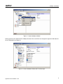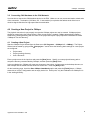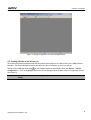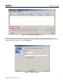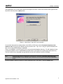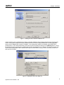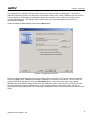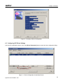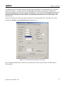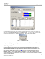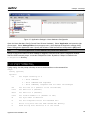
1
CANape - First Steps
Version 1.1
2005-02-28
Application Note AN-AMC-1-105
Restrictions
Abstract
Public Document
The purpose of this application note is to give a step-by-step guide to establishing a connection to an ECU
using the ASAM standard, CCP (CAN Calibration Protocol). This document provides basic information on
how to create a CANape project, create a CCP driver type device and configure ECU parameter settings.
Table of Contents
1.0
2.0
3.0
3.1
3.2
4.0
4.1
4.2
4.3
4.4
4.5
5.0
6.0
7.0
8.0
9.0
Overview ..........................................................................................................................................................1
CCP Driver in the ECU ....................................................................................................................................1
Configuring the Hardware ................................................................................................................................2
Assigning CANape to Physical Channels .....................................................................................................2
Connecting CAN Hardware to the CAN Network..........................................................................................4
Creating a New Project in CANape .................................................................................................................4
Creating a New Project .................................................................................................................................4
Adding a Device to the Device List ...............................................................................................................5
Configuring CCP Driver Settings.................................................................................................................10
Creating a Database ...................................................................................................................................12
Adding Database Objects to Display Windows...........................................................................................13
CCPlog...........................................................................................................................................................13
Frequently Asked Questions..........................................................................................................................15
Important Details, Special Constraints, or Other Influences..........................................................................15
Additional Resources .....................................................................................................................................16
Contacts .........................................................................................................................................................16
1.0 Overview
CANape (CAN Application Environment) is an ASAM-MC-compliant measurement, calibration, test, and software
development tool for electronic devices. Its main components include online and offline data analysis, direct read
and write access to electronic control unit (ECU) memory, data management, synchronous periodic and eventdriven data acquisition, flash programming, and an ASAM-MC2 controller device database editor. Connections to
multiple ECUs are possible over CAN and other network buses such as Ethernet, Serial, and USB.
The purpose of this application note is to give a step-by-step guide to establishing a connection to an ECU using
the ASAM standard, CCP (CAN Calibration Protocol). This document provides basic information on how to create
a CANape project, create a CCP driver type device and configure ECU parameter settings.
2.0 CCP Driver in the ECU
A CCP Driver must be integrated in the ECU before CANape can connect to it. The Vector CCP Driver is included
with the CANape software package free of charge. Unzip the file CCP.EXE, located in the CCP directory of the
CANape software CD. The driver files CCP.C, CCP.H, and the configuration file CCPPAR.H are located in the ccp
directory. A sample CAN Driver interface to the CCP file (CAN_CCP.C) is located in the CANDRV directory as
well as the instruction file (CCP_DEMO.PDF) for integrating the CCP Driver with the ECU application. Please read
CCP_DEMO.pdf in the CANDRV folder and CCP.DOC in the DOC folder before integrating the CCP Driver.
1
Copyright © 2008 - Vector CANtech, Inc.
Contact Information: www.vector-cantech.com or 1-248-449-9290
CANape - First Steps
CCPPAR.H is the CCP Driver configuration file that contains the CRO (Command Receive Object), DTO (Data
Transmit Object), and ECU (station) address information that will be used to configure CANape. If using a Vector
CAN Driver, the CCP Driver can be configured via the CANgen tool.
/* CCP parameters */
/* CCP Identifiers and Address */
#define CCP_STATION_ADDR
*/
0x0039
/* Define CCP_STATION_ADDR in Intel Format
/* High/Low byte swapped on Motorola machines
!!! (0x3900) */
#define CCP_STATION_ID
"LedProj"
/* Plug & Play station identification */
#define CCP_DTO_ID
0x7E1
/* CAN identifier ECU -> Master */
#define CCP_CRO_ID
0x667
/* CAN identifier Master -> ECU */
CANape interprets CCP_STATION_ID as the file name for the ECU controller description file. A benefit of this is
that the correct ECU database is automatically assigned via the Plug and Play mechanism when the CANape
program starts. If it is not possible to access to the CCPPAR.H file, the ECU developer should provide the
necessary information. Detailed information on these identifiers is available in the document CCP.DOC.
After CCP integration is done, build the application and download it to the ECU. It is recommended that a linker
map file created on build is used to build the controller description file.
The current CCP version is 2.1 and the Vector CCP Driver version is 1.42.
3.0 Configuring the Hardware
CANape uses a maximum of eight logical CAN channels. To make a physical connection to an electronic control
unit, CANape logical channels must be assigned to the physical channels of the CAN hardware device
(CANcardXL, CANcardX, CAN-AC2, CAN-AC2 PCI).
3.1 Assigning CANape to Physical Channels
Start the Vector Driver configuration program from the Vector Hardware icon in the Control Panel (Start →
Settings → Control Panel). All CAN devices installed on the computer are listed under the Hardware tree. It is
possible to assign the logical CANape channels to the physical hardware channels. To do this, select the
hardware channel and press the right mouse button. Select ‘CANape’ in the popup menu, then select e.g.
CANcardXL Channel, then press the right mouse button and select a logical CANape channel (see Figure 1).
2
Application Note AN-AMC-1-105
CANape - First Steps
Figure 1 - Vector Hardware Window
Opening the tree view shows that the CANape channels CAN 1 and CAN 2 are assigned to physical CAN channels
on the CANcardXL (see Figure 2).
Figure 2 - Vector Hardware Window with TreeView Open
3
Application Note AN-AMC-1-105
CANape - First Steps
3.2 Connecting CAN Hardware to the CAN Network
It is now time to connect the CAN hardware device to the ECU. Make sure to use correct termination at both ends
of the connection. Termination (120 Ohms, 5%, ¼ watt resistor) is required at the farthest ends of the bus to
minimize signal reflections for high-speed data communication.
4.0 Creating a New Project in CANape
The physical connection is now properly set up and a CANape project can now be created. CANape projects
should be created using the Project Wizard. When a new project is created, CANape automatically creates a
subdirectory (working directory) with the name of the project and copies a project-specific initialization file called
‘CANape.ini’ into this directory.
4.1 Creating a New Project
Start the CANape Project Wizard from the Start menu (All Programs → CANape 6.5 → CANape). The Project
Wizard can be started by going to FileÆNew project… and is where the following basic settings for a new project
are configured:
•
•
•
Project name
Project (working) directory
Links / Shortcuts
Enter a project name in the input box and press the [Next] button. Specify your own project directory path or
accept the directory recommended by CANape, and then press the [Next] button.
In the next dialog box, CANape will create two shortcuts to the project. At least agree to the desktop shortcut, so
that CANape can be started with this shortcut at a later time. Press the [Next] button.
On the last dialog page, check the Start CANape immediately option and press the [Finish] button. CANape
starts with an “empty” configuration and an empty device list. At this point, only the initialization file CANape.ini is
in the working directory.
4
Application Note AN-AMC-1-105
CANape - First Steps
Figure 3 - Empty Configuration in a New CANape Project
4.2 Adding a Device to the Device List
All controller and external measurement data acquisition devices have to be made known to the CANape Device
Manager. The Device Manager accesses the data in the device list where our device is defined.
on the CANape toolbar or selecting the menu item Device → Device
Start the Device Manager by clicking
Configuration… Click on the [New] button in the Device Manager, which will start a Device Configuration wizard
(see Figure 4).
Note:
You will see a drop-down list on the [New] button. Ignore the other options for now and select
[New].
5
Application Note AN-AMC-1-105
CANape - First Steps
Figure 4 - Empty Device Configuration List
Enter the device name. The name can be the same as CCP_STATION_ID in the CCPPAR.H file in the CCP
Driver or any project-specific name. The name entered here serves as a unique identifier for the device, and once
created cannot be changed later. Press the [Next] button.
Figure 5 - Enter Device Name
6
Application Note AN-AMC-1-105
CANape - First Steps
In this application note, we will create a device of the type CCP Driver. Select CCP to be the driver type from the
drop-down list and press the [Next] button.
Figure 6 - Select Driver Type (CCP in this example)
If a controller description file already exists in the ASAP2 or DB format, uncheck Automatic detection of the
database name and specify the database directory and file name. Say ‘Yes’ to using the specified database file
and ‘Yes’ to using ASAP2 settings, if applicable.
If there is no database, create an empty one by leaving the default database directory. The A2L database format
is selected by default, since it is ASAM-MC2-compliant and the specifications are public (http://www.asam.net).
The A2L format is more compatible among different tools and even different versions of CANape.
Note:
If the controller does not support the Plug and Play mechanism, Automatic detection of the
database name must be disabled and a database must be selected by pressing the [Browse]
button.
It is also possible to specify a directory for storing parameter files in this dialog. Press the [Next] button.
7
Application Note AN-AMC-1-105
CANape - First Steps
Figure 7 - Settings for the Controller Database File
A linker map file can be used directly to create a controller database during program development (see Figure 8).
If there is a program change that results in address shifts in the linker map file, addresses of existing database
entries can be updated upon request in CANape. If an existing linker map file is available, select MAP file(s)
predetermined. Then select the directory where the map file is located by clicking on the [Browse] button. Select
the map file format by selecting the compiler type from the drop-down list. For example, if a Cosmic compiler was
used to build the application and create an IEEE map file, select IEEE (Tasking, Cosmic, Microtec) from the list
and enter the file name.
Figure 8 - Settings for the Linker Map File
8
Application Note AN-AMC-1-105
CANape - First Steps
The settings for the controller’s HEX file (cache memory) are entered on the next dialog page. The values of
calibration objects are placed in this file and can be changed in offline mode. When CANape is exited or the ECU
is disconnected, all values that were changed are stored in the HEX file xx.hex, where xx is the name of the
controller database used. The changes made in offline mode can only be downloaded when the ECU is
reconnected to CANape.
Accept the default CANape settings and press the [Next] button.
Figure 9 - Settings for the Hex File
We are now at the last dialog page of the Device Wizard, where a summary of CCP device settings is displayed.
Click on the [OK] button. CANape then attempts to establish a connection to the controller. Since we have not
configured the driver settings yet, click on the [Go Offline] button. At this point, if the name of an existing
database was not specified, CANape will ask for a new database file name. Enter the CCP_STATION_ID value
from the CCPPAR.H file as the database name. In this example ‘LedProj’ is used as the name. Say ‘No’ to
importing an existing database and ‘Yes’ to creating a new database, which exits and then returns to the device list
dialog.
9
Application Note AN-AMC-1-105
CANape - First Steps
Figure 10 - Summary of Device Configuration
4.3 Configuring CCP Driver Settings
In the device configuration window, click on the [Driver Parameters] button to open the driver configuration dialog.
Figure 11 - Device Configuration List with New Device
10
Application Note AN-AMC-1-105
CANape - First Steps
To establish a connection with the controller, the basic settings needed are the CRO identifier, the DTO identifier
and the ECU address. The CRO is the CAN message that transmits CCP commands from CANape to the
controller, and is defined as CCP_CRO_ID in the CCPPAR.H file. The DTO is the CAN message that forwards the
response transmitted by the controller to CANape and is defined as CCP_DTO_ID in the CCPPAR.H file. Enter
the CRO and DTO information in the input fields. The ECU address is defined as CCP_STATION_ADDR in the
CCPPAR.H file.
Set the ECU format to be either Intel or Motorola based on your microprocessor type. Select the CCP version.
Uncheck the ‘SeedKey’ and ‘Overload detection’ settings for now.
Figure 12 - Driver Parameter Settings for CCP Device
In the Transfer parameter section, select the correct CAN channel (CAN 1) and set up the baud rate and bus
timing registers.
11
Application Note AN-AMC-1-105
CANape - First Steps
Figure 13 - Baud Rate and Bus Timing Register Settings in CANape
All needed settings have now been made to establish a connection with the ECU. To see if it is possible to go
online, click on the [Test Connection] button under the Parameter tab. If the settings made are correct and a
connection is made to the device, a message will be displayed: ‘(device name): ECU is ONLINE’.
Figure 14 - Communication is OK
Congratulations! CANape has successfully established a connection with the ECU. Close the CCP Device Setup
window and the Device Manager window.
4.4 Creating a Database
In order to measure and calibrate the ECU data objects, a controller description file must be created. The
associated map file contains the object name and its memory address. Based on the map file format, it may
contain more useful information like data type, etc.
button on the toolbar or by selecting the menu item
Open the ASAP2 database editor by clicking on the
Database → Editor…. If a new database has been created, this will be blank. We can directly insert ECU
variables into the database using the linker map file. It is possible to create measurement, parameter or calibration
objects, and virtual signal types.
12
Application Note AN-AMC-1-105
CANape - First Steps
In the ASAP2 Database Editor, select the menu item Edit → Insert from map file… A dialog page opens with a
list of all map file objects and their addresses. Select an object from the list to be calibrated and press [OK]. Click
the [Calibration] button as the object type. A parameter object can now be seen in the database, and it is
symbol. (Refer to the CANape User manual for a detailed description of all database symbols).
denoted by the
Insert another variable from the map file, but this time as a measurement object, denoted by the
symbol.
Now there is one object to be calibrated and one object to be measured. Save and close the database editor.
4.5 Adding Database Objects to Display Windows
CANape offers options to display database objects in multiple formats. Measurement objects can be displayed in
graphic, numeric, digital, or bar format. Calibration objects can also be displayed in graphic or numeric format.
Go to the CANape menu item Display → Calibration Windows → Calibration Window. Select the desired
calibration variable to be read and modified from the popup database and click the [Apply] button in the toolbar.
Close the database.
To display a measurement object, the object first has to be added to the Measurement Configuration List. Go to
icon on the toolbar. Right click
the menu item Measurement → Measurement configuration… or select the
in the right window and select ‘Insert Signal…’, which will open the Database Editor where the desired
measurement object can be selected. Select the measuring mode to be polling at 100ms. If a DAQ has been
implemented in the ECU, it is possible to create timer events (please refer to CCP_TEST.PDF for more
information). Close the configuration list.
Select the menu item Display → Measurement Windows → Graphic window… Right click in the empty window
and select ‘Insert measurement signal…’. Select the measurement signal from the measurement configuration
list and click [Apply]. Close the configuration list.
Click on the
symbol in the toolbar to run the measurement. If CANape is not online, a prompt will ask if
CANape should be connected. Say ‘Yes’ to connect.
At this point you are connected to the ECU and successfully using measurement and calibration options of
CANape.
5.0 CCPlog
CANape CCP communication to the ECU can be monitored and logged using the CCPlog utility that is included in
the CANape installation. The file CCPLOG.EXE is located in the CANape\Exec folder.
Note:
It is recommended to start CCPlog before starting CANape to capture CANape initialization
messages as well.
13
Application Note AN-AMC-1-105
CANape - First Steps
Figure 15 - Application Settings in Vector Hardware Configuration
Open the Vector Hardware Config (Control PanelÆVector Hardware). Select ‘Application’ and press the right
mouse button. Select ‘Add application’ from the popup menu, which displays the Application settings dialog.
Enter CCPlog as the Application name. Specify the Number of CAN channels as 1 and press the [OK] button.
Note:
The CCPlog application in Vector Hardware only needs to be added once.
Assign CCPlog to the channel to which CANape is assigned. Close the Vector Driver Configuration window.
Start the DOS command prompt. Locate the CANape\Exec folder. By default, CANape is installed in the
C:\Program Files directory.
Typing ccplog –h at the prompt calls help on how to set the switches on the command line.
Usage:
CCPlog [options]
Options:
-tx
Set output verbosity to x
1 - Print commands
2 - Print commands and responses
3 - Print commands, responses and all other can messages
-bx
Set bit rate to x (Default is not initialized)
-crox
Set CRO id to x (decimal)
-dtox
Set DTO id to x (decimal)
-verx
Set version number to x (default is 200)
-m
Set byte order to Motorola
-e
Set the acceptance filter for extended id's
-l
Write a Log File with the name CCPLOG.LOG (Binary)
-o
Read the Log File and write it to the screen
14
Application Note AN-AMC-1-105
CANape - First Steps
Keys:
0-3
s
Set output verbosity to x
Print Statistics
For example, if CANape is assigned to CANcardXL Channel 1 with baud rate = 500K, CRO = 0x667, and DTO =
0x7E1, enter the following at the prompt:
The value 1639 is decimal for 0x667 and 2017 is decimal for 0x7E1. These values will show the CCP
communication on the screen.
If a log file of these messages is needed, add > log.txt at the end of the above command like this:
Adding this will create a LOG.TXT file in the CANape\Exec folder with CCP messages. Refer to the CCP21.PDF
document under the CCP\CCP.EXE file in the CANape installation CD, which contains the breakdown of each
CCP command and response.
Press the <ESC> key at any time to stop CCPlog.
6.0 Frequently Asked Questions
1. The error message “CAN: CAN-ERROR: No hardware channel assigned to logical channel 1” is generated when trying
to connect CANape to the ECU.
CANape is not assigned to correct physical channels. CANape is most likely assigned to virtual channels. Go to Start
→ Settings → Control Panel and double click on the Vector Hardware icon. Assign CANape 1 to hardware Channel
1 and CANape 2 to hardware Channel 2.
Note:
If the CCPsim demo program is run using the CCPsim ECU simulator, CANape will be
automatically assigned back to virtual channels.
2. The error message “yourDeviceName: No response from ECU” is generated when the [Test Connection]
button
under Driver Configuration is clicked.
There can be a number of reasons why CANape would not be able to connect to the ECU:
a)
b)
c)
d)
CANape logical channels are not assigned to correct hardware channels. (See Section 3.1)
CAN cable connections are not properly terminated. (See Section 3.2)
The specified baud rate and bus timing registers in CANape are not matching the values in the ECU.
CRO, DTO and station address values in CANape under driver configuration are not matching the
ones in the ECU. (See Section 4.3)
7.0 Important Details, Special Constraints, or Other Influences
The example provided in this application note is generated using CANape Version 6.5 Service Pack 3.
15
Application Note AN-AMC-1-105
CANape - First Steps
8.0 Additional Resources
The following material may provide further useful information:
AVAILABLE ON VECTOR’S WEBSITE
• CANape User Manual
• Network Interfaces Installation Guide and Manual
OTHER RESOURCES
• CANape Online Help
• The CCP CAN Calibration Protocol V2.1 and the free CCP Driver can be found at the following website:
http://www.vector-cantech.com
9.0 Contacts
Vector Informatik GmbH
Ingersheimer Straße 24
70499 Stuttgart
Germany
Tel.: +49 711-80670-0
Fax: +49 711-80670-111
Email: [email protected]
Vector CANtech, Inc.
39500 Orchard Hill Pl., Ste 550
Novi, MI 48375
USA
Tel: +1-248-449-9290
Fax: +1-248-449-9704
Email: [email protected]
VecScan AB
Theres Svenssons Gata 9
41755 Göteborg
Sweden
Tel: +46 (0)31 764 76 00
Fax: +46 (0)31 764 76 19
Email: [email protected]
Vector France SAS
168 Boulevard Camélinat
92240 Malakoff
France
Tel: +33 (0)1 42 31 40 00
Fax: +33 (0)1 42 31 40 09
Email: [email protected]
Vector Japan Co. Ltd.
Seafort Square Center Bld. 18F
2-3-12, Higashi-shinagawa,
Shinagawa-ku
Tokyo 140-0002
Japan
Tel.: +81 3 5769 7800
Fax: +81 3 5769 6975
Email: [email protected]
Vector Korea IT Inc.
Daerung Post Tower III, 508
182-4 Guro-dong, Guro-gu
Seoul, 152-790
Republic of Korea
Tel.: +82-2-2028-0600
Fax: +82-2-2028-0604
Email: [email protected]
16
Application Note AN-AMC-1-105