1
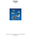
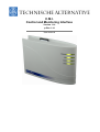
C.M.I.
Control and Monitoring Interface
Version 1.14
p-files 1.14
User manual
Hardware / General
Function
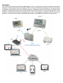
The control and monitoring interface (abbreviation: C.M.I.) is a web server that can create the connection
between a LAN network and the controller UVR1611 with its CAN bus components. This device makes
it possible to load function data into CAN bus devices, update and remote control them, illustrate online
diagrams and log data. Access can be local directly from the PC/network, via Internet and the C.M.I. web
portal or via Internet through port forwarding to the router. Data logging of devices with DL Bus is also
possible. It was ensured to make commissioning as easy as possible for computer novices as well.
Power supply
Operation of the C.M.I. requires 12V supply from CAN bus or a 12V-power pack. Power is not supplied
via DL bus.
To safeguard the power supply for additional CAN bus members without their own power supply
per UVR1611, the use of a 12V power supply is absolutely necessary.
Data retention is also ensured without power supply.
CAN bus
Next to data transfer, the CAN bus offers also the possibility to directly access the devices in the CAN
network from the PC via browser.
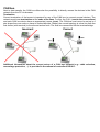
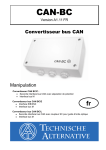
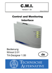
Termination
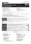
Correct termination of the buses is important for use of the CAN bus to connect several devices. The
network must have terminations at the ends of the lines. For this, the C.M.I. (next to the connections)
and each CAN bus device have an appropriate jumper (term). The CAN bus must never be set up in a
star shape from one node or clamp to several devices. Rather, the correct topology is a bus line from the
first device (with terminal) to the second and so forth. The final bus connection has the terminal bridge.
Incorrect
Correct
Additional information about the correct set-up of a CAN bus network (e.g.: cable selection,
overvoltage protection, …) is provided in the manual of controller UVR1611.
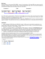
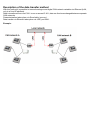
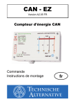
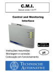
DL bus
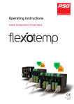
Every controller of the series ESR (ESR21 version 5.0 and higher), UVR and HZR has a data output DL
that forms, together with the (sensor) earth, a two-pole data line (DL bus). The C.M.I. has 2 DL inputs for
simultaneous measurement recording of up to two controllers.
Controller 1
C.M.I.
Controller 2
Any cable with a cross section of 0.75 mm² and a length of up to max. 30 m can be used for the data
line (e.g. twin-strand). For longer cables, we recommend the use of shielded cable whereby the cable
shielding must be connected with the sensor earth.
If two controllers are recorded with the C.M.I., separately shielded cables must be used as protection
against crosstalk. The data link for the DL bus must likewise never be run in one cable with the CAN bus.
WARNING:
# With controllers UVR1611K and UVR1611S, output 14 (DL) can be used either as data line or as
switch output (with extra auxiliary relay). For data logging via DL bus, output 14 must therefore always
be defined as a “Data line” in the “Outputs” menu.
# With the controllers UVR1611 of the E-series (“board version“), output 14 is simultaneously used
as switch output OUTPUT 14 and data line (DL bus). For activation, the output must be parameterised
as a “Switch output”, even if the data link is to be activated. For activation of the data line, the query
“UVR1611E:” must additionally be answered with ”yes” (see additional manual for UVR1611 E).
# UVR1611 controllers from version A2.16 additionally enable the recording of network input
variables, which are handled by the C.M.I. as a virtual second UVR1611. When
parameterising output 14 as a “Data line”, the menu option NETW.EG.=>DL.: must be answered with
yes. Recording of network variables is therefore not possible, if two controllers are connected with the
C.M.I. (this note applies only to data recording via DL bus).
The scope for data recording of this 2nd virtual UVR1611 in the menu “Settings/Data logging“ of the
C.M.I.s must be set like this:
Commissioning
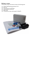
Delivery scope
The delivery scope of the device includes the following parts:
1 pc. Control and Monitoring Interface C.M.I.
1 pc. SD card
1 pc. 4-pole plug for the CAN bus
1 pc. 3-pole plug for the DL bus
1 pc. Brief guide
1 pc. 12V power unit (only with model: 01/CMI-NT)
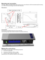
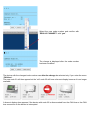
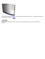
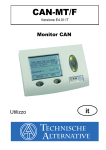
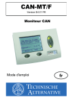
Mounting and connection
The C.M.I. can be assembled either with 2 screws on an even surface or with the enclosed rapid mounting
to a TS35 DIN rail according to the EN 50022 Standard.
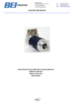
Dimensions:
Connections
Connections are labelled and must not be confused.
The following Figure also shows termination on the left (CAN bus).
Making the connections
Connections must be made in the following sequence
1. Connection LAN cable
2. Connection CAN bus or DL bus cable
3. Optional: power supply with power unit
(positive pole on the internal conductor, earth outside)
The POWER LED now has to be green permanently.
IP-Address
Access requires an IP address.
Network with DHCP server (standard)
The network settings are determined automatically.
Network without DHCP server
Direct C.M.I. connection– Windows PC
DHCP must be activated on the PC.PC and C.M.I. automatically gets an IP address this way. This process
can take more than 1 minute.
Fixed IP address
1. Create a text file with the name fix_ip.txt with the required IP address in the root directory of the SD
card. The content of this file must be only an IP address (example: 192.168.0.10) and "Enter".
2. Insert the SD card in the C.M.I.
3. During the next start, the C.M.I. adopts this IP address and deletes the txt file on the SD card.
The network settings must then be configured locally (C.M.I. menu Settings/Ethernet).
The LAN LED now has to flash green or be green permanently.
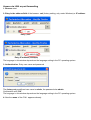
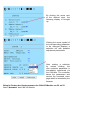
Access via browser
Access via LAN or port forwarding
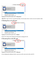
1. Browser start
2. Entry in the address field of the browser: cmi (factory setting, only under Windows) or IP address
Entry „cmi“
Entry IP address (example)
The language in this window depends on the language setting in the PC operating system.
3. Authentication: Entry user name and password
The factory-set predefined user name is admin, the password also admin.
Confirmation with "OK".
The language in this window depends on the language setting in the PC operating system.
4. Now the menu of the C.M.I. appears already.
Further operation is described in chapter "C.M.I. menu".
Access via C.M.I. web portal https://cmi.ta.co.at
IIf you want access via Internet, then the C.M.I can be connected via “„C.M.I. web portal“. The C.M.I.
web portal is a server that was set up by Technische Alternative.
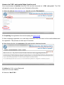
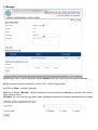
1. Select the address https://cmi.ta.co.at, „Log in“ and click "Registration".
2. Completing the registration form and accepting the terms of use
3. After completing registration, an e-mail with an activation link will be sent to the e-mail address used
for registration. This process can take up to 30 minutes.
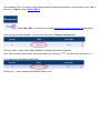
4. After clicking the link, the start page of the web portal is displayed already.
5. Adding the C.M.I. in the Web portal
Selection of the tab “C.M.I.s“
6. Selection “Add C.M.I.“
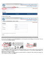
7. Entry of C.M.I. data
On the rear of the device is the serial number on the rating plate and the key on the key label. The key
must be entered without spaces.
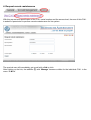
The "Designation“ helps with the selection of several individual C.M.I.s and is visible in the list of individual
C.M.I.s. If service by the super user (e.g. Technische Alternative) is to be allowed at all times, the
appropriate field will be checked.
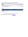
After clicking on “Add“, a message about successful addition is displayed. After updating the page, the
C.M.I. appears in the list “My C.M.I.s“.
8. After updating the page, the C.M.I. appears in the list “My C.M.I.s“.
Clicking on the serial number takes you to the C.M.I. menu.
Further operation is described in chapter "C.M.I. menu".
Resetting and loading of factory settings
Briefly pressing the reset key on the rear of the C.M.I. restarts the C.M.I. (reset).
If the reset button is pressed and released while the red LEDs are still illuminated, resets the C.M.I. to
factory settings.
Caution: Pressing the reset button until the red LEDs stop being illuminated starts a firmware update with
the C.M.I. operation system saved to the SD card. The current firmware in the “UPDATE“ folder of the
SD card must be called “CMI.BIN”.
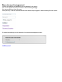
Web portal cmi.ta.co.at
Menu Account management
Contact information and password can be changed in this menu.
The current password must be entered to finalise every change.
It is also possible to delete the user.
During the log, it can be specified that the user always stays logged in when selecting the web portal:
All saved user settings can be deleted in the account management menu.
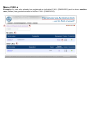
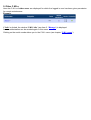
Menu C.M.I.s
Example of a user who already has registered an individual C.M.I. (CMI000501) and to whom another
user (stefan) has granted access to his/her C.M.I. (CMI001015):
1. Add C.M.I.
This application is described in the chapter “Access via C.M.I. web portal https://cmi.ta.co.at “.
2. My C.M.I.s
All C.M.I.s of the logged in user are listed here with a shortcut.
Clicking on the serial number takes you to the C.M.I. menu (see chapter “C.M.I. menu“).
3. Manage
a) Clicking on the - next to the serial number deletes this C.M.I. and it can no longer be selected.
b) The summary and the description of the C.M.I. can be changed here.
c) Click on “Save“ to finalise changes.
d) In the submenu “Manage”, remote maintenance can be authorised directly for another user whose
login name is known.
Example: The user with the login name “rim“ is granted permission for remote maintenance as an expert.
The released C.M.I. for which remote maintenance as expert was granted is now shown to user “rim“ in
the menu “C.M.I.s” under “Other C.M.I.s“.
Under "My C.M.I.s", this shows that one request for remote maintenance was made:
After clicking on Administration, you can see in the area " Remote maintenance “:
The user “rim“ (=login name) has submitted a remote maintenance request.
+“) or refused (by clicking on “-“).
Now, either remote maintenance can be permitted (by clicking on “
If it is permitted, the display changes to:
Clicking on “-” can revoke this permission at any time.
4. Request remote maintenance
With this request with specification of the C.M.I. serial number and the access level, the user of this C.M.I.
is asked for permission to perform remote maintenance for his system.
The queried user will immediately get a mail with a link to click.
After clicking on the link, the addition (1) with “Manage“ becomes visible for the individual C.M.I. in the
menu “C.M.I.s”.
5. Other C.M.I.s
Here the C.M.I.s of other users are displayed for which the logged in user has been given permission
for remote maintenance.
Example:
If “Info“ is clicked, the window “C.M.I. Info“ (see item 3. “Manage“) is displayed.
Access authorisation can be revoked again in this menu.
Clicking on the serial number takes you to the C.M.I. menu (see chapter “C.M.I. menu“).
C.M.I. menu
Local operation (LAN): Access to the C.M.I. menu by calling the browser and entering the host name
or the IP address of the C.M.I.. Subsequently authentication with user name and password (expert, user
or guest).
Operation via web portal (Internet): Entry of the C.M.I. web portal name (https://cmi.ta.co.at) and log
in. Selection of the tab "C.M.I.s“ and clicking on the serial number of the desired C.M.I.. A new tab with
the designation of the device opens.
In the now opened page, the user level can be seen on the top right and the version and the serial number
of the C.M.I. is visible on the bottom right.
There are 6 different submenus that are described in the following:
# Home
# CAN bus
# Schematic
# Data administration
# Settings
# Status
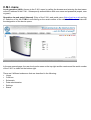
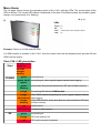
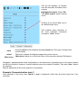
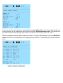
Menu Home
The 1st page (Home) shows the operating status of the C.M.I. with the LEDs. The actual status of the
LEDs is shown. The current LED status is explained on the side. Six different states are possible: green,
orange, red, permanently lit or flashing.
Example: Failure of a CAN network node.
If a GSM module is installed in the C.M.I., then the menu Home will be displayed with provider ID and
GSM receiver quality.
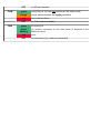
Table C.M.I. LED description
Start
all LEDs red =
power on
all LEDs
orange=
booting
POWER
green
everything ok
green, short everything ok, short regular lapses indicate data logging
lapses
green
flashing
at the start files are transmitted from SD card to flash memory
orange
Everything OK with the GSM module
orange.
With GSM module:everything ok, short regular lapses indicate
short lapses data logging
orange
flashing
red
red flashing
SD
green
orange
red
With GSM module: at the start files are transmitted from SD card
to flash memory
internal error
no files in flash memory
everything ok
SD card memory full
SD card incorrectly formatted
OFF
CAN
green
orange
LAN
no SD card inserted
everything ok (at least one additional CAN node found)
not all essential nodes for logging available
red
one node has failed
OFF
no CAN network available
green
green
flashing
everything ok
no reverse connection to the web portal (if selected in the
Ethernet menu)
red
error
OFF
no connection (e.g. cable not connected)
Menu CAN-Bus
This menu shows the devices in the CAN bus network with their designation and node number displayed.
The C.M.I. has node number 56 with factory settings.
Example of a CAN network with one controller UVR1611, one CAN I/O module and one CAN – bus
converter CAN-BC:
Clicking on one of the devices takes you to the device menu.
The operating status of the C.M.I. LEDs is not displayed on this page.
Remote maintenance of CAN bus devices
Example: UVR1611 node 1
Only the values current at the time of loading of the page that are displayed. In order to display the
actual (latest) values, the page must be refreshed.
The top row displays, as familiar
from the controller, the status of the
outputs:
Highlighted in black: Output ON
The hand symbol means manual
mode.
Clicking on an arrow takes you to
the selected sub-menu.
This enables direct selection of
the most important submenus
(exception: “User” menu).
back
reload
Main menu
Using the back function displays the page shown last. This may no longer show
current values.
This button reloads the displayed page with current values.
“Main menu“ takes you to the main menu of the currently selected CAN device.
Navigation, parameterisation and configuration in the submenus is generally done in the same manner
as with the controller. However, function modules cannot be created or deleted. The menu “User“ cannot
be selected.
Manual adjustment of the mixer outputs is not possible.
Example: Parameterisation input 1
After selection of the menu item “Inputs” a page is displayed, which has the same layout as in the
controller.
By clicking the arrow next
to the desired input, the
following display is brought
up:
Clicking the arrow symbol of
the corresponding parameter
to be changed displays a
selection list with possible
adjustment parameters.
After making a selection
by mouse clicking, the
new controller parameter is
immediately transferred via
the CAN-bus. The controller
saves the parameters and
returns the corrected menu
page which is reloaded by the
browser.
Beispiel: Ändern der Knotennummer des CAN-I/O-Moduls von 32 auf 31
Menü „Netzwerk“ des CAN-I/O-Moduls
Select the new node number and confirm with
“REALLY CHANGE?“ with “yes”.
The change is displayed after the node number
has been modified.
The device with the changed node number can after the change be selected only if you enter the menu
“CAN bus“.
The new node 31 will then appear but the “old“ node 32 will have a timeout display because it is no longer
available.
A timeout display also appears if the device with node 32 is disconnected from the CAN bus or the CAN
bus connection to the device is interrupted.
A missing CAN node is indicated by the red LED for the CAN bus on the C.M.I.. This display is also visible
in the browser in the menu “Home“.
“CAN reload“ reloads the network nodes and all non-existing nodes are no longer displayed with
timeout.
Menu Schematic
Selecting this menu item displays the online schematic (if programmed). Programming of the online
schematic with “TA-Designer” is described in the program's online tutorial.
Direct local access to the online schematic without login can be done by entering the following URL:
http://user:password@cmi/schema.html#1
User: user name for expert, user or guest
Password: password defined for the respective user
cmi: host name or IP address of the C.M.I.
schema.html#1: page 1 of the online schematic is called
System requirements
UVR1611: at least operating system version A3.25
CAN-I/O modules: at least operating system version A2.02
CAN-BC bus converter: at least operating system version A1.10
CAN-EZ energy meter: at least operating system version A1.03
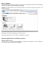
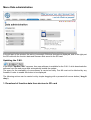
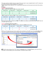
Menu Data administration
In the left part of the window, the active (connected) CAN bus devices are displayed, and in the right part
the SD card with the function data and firmware files saved to the SD card.
Updating the C.M.I.
If the button "Update C.M.I." appears, then new software is available for the C.M.I. A click downloads the
software from the web server and automatically installs the update.
The query for the availability of new software is carried out daily. Port 80 must not be blocked by any
firewalls in order to enable this button to be displayed.
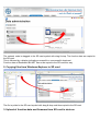
The following actions can be carried out by simple dragging with a pressed left mouse button (“drag &
drop“):
1. Download of function data from devices to SD card
The network node is dragged to the SD card symbol with drag & drop. The function data are copied to
the SD card.
This is followed by a display indicating successful or unsuccessful download:
Function data of Bootloader BL-NET cannot be copied to the SD card this way.
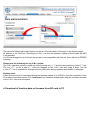
2. Copying files from Windows-Explorer to SD card
The file is pulled to the SD card symbol with drag & drop and thus copied to the SD card.
3. Upload of function data and firmware from SD card to devices
The upload is started with drag & drop from the list of function data or firmware to the device symbol.
All devices in the CAN bus, including the C.M.I., can thus be updated. Update of boot loader BL-NET
is not possible.
If a file was dragged to an incorrect device that is not compatible with this file, there will be an ERROR
message.
Please note the following for any C.M.I. update:
The C.M.I. operation system is made up of the firmware cmi_V*.** and the user interface p_files.V*.**.bin.
The cmi_V*.** or the p_files.V*.** must be dragged to the C.M.I. field with drag & drop. The file
p_files.V*.**.bin is checked for changes at every start (also during updates) and loaded, if necessary.
Problem case:
If the CAN connection is interrupted during the firmware update of a UVR1611, then the controller in node
63 is without operation system. For a new start of the firmware update again, drag the controller firmware
to the C.M.I. icon as an exception.
4. Download of function data or firmware from SD card to PC
Highlight the desired file and click on “Download“.
“Save file“ copies the file to the download folder of the browser where it can be moved to another folder.
5. Deleting files on the SD card
Highlight the desired file and click on “Delete“.
Answer the subsequently displayed confirmation message with Ok.
6. Renaming files on the SD card
Highlight the desired file and click on “Rename“.
In the subsequently displays window, enter the new file name and confirm with Ok.
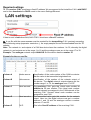
Menu Settings
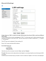
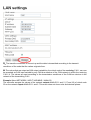
Ethernet (LAN settings)
If more than one C.M.I. is used in the same LAN network, then these C.M.I.s must have different
host names.
In this example, the host name was changed to "CMI1". The host name can be freely selected and does
not require a reference to the word “CMI“. The host name may not include an underscore ("_"); a hyphen
("-") is permitted.
The HTTP port can be adjusted. Factory setting: 80
Every C.M.I. has an individual MAC address:
After the entry of the new name, first click “Save“ and then “Restart“.
Firewall: With access via the web portal and mail dispatch, an existing firewall must not block ports 40001
and 40002.
Port 80 must not be blocked by any firewalls in order to enable the "Update C.M.I" button to be displayed.
Direct connection C.M.I. - PC
DHCP is activated in the factory setting. The C.M.I. tries to obtain a valid IP address from the network
on its own.
If there is no DHCP server in the network, automatic IP allocation will be started. An IP address between
169.254.0.1 and 169.254.254.255 is allocated. The subnet mask is 255.255.0.0. This process can take
more than 1 minute.
The C.M.I. can be selected directly with the host name in Windows in the browser. If the name resolution
does not work, you have to proceed as described in chapter “Connection without DHCP“.
Connection without DHCP
The user can specify the parameters (IP address etc.) manually.
This can be done in the web interface. If access via the web interface is impossible, there is the possibility
to define a fixed IP address with a file:
A text file with the name fix_ip.txt with the desired IP address is created in the root directory of the SD
card. The content of this file may consist only of an IP address (e.g. 192.168.0.10) and “Enter“.
During the next start, the C.M.I. will adopt this IP address, deactivate DHCP and reverse (web portal) and
delete the txt-file on the SD card.
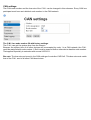
CAN settings
The CAN node number and the bus rate of the C.M.I. can be changed in this submenu. Every CAN bus
participant must have an individual node number in the CAN network.
The C.M.I. has node number 56 with factory settings.
The C.M.I. can get the system time from the Internet.
Because the system time of all other devices will be accepted by node 1 in a CAN network, the C.M.I.
could be assigned with node number 1. But it must be ensured that no other device has this node number.
That applies especially to networks with several UVR1611.
Bus rate: The bus rate can be set in the CAN settings of controller UVR16x2. This bus rate must match
that of the C.M.I. and of all other CAN bus devices.
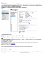
Messages
The values and conditions for mail and SMS dispatch can be determined in the menu “Messages”. It is
only possible to send text messages with the built-in GSM module. The values are accepted either by
CAN or DL bus. Up to 32 messages are available.
Example for a message in case of excess collector temperature:
1.
2.
3.
4.
5.
Message designation
Selection of the bus: CAN bus or DL bus DL1 or DL2
Only with CAN bus: specification of reference node
Source: Analogue or digital network output with CAN bus, input or output with DL bus
Sending condition: Analogue values: equal =, greater >, greater or equal >=, less <, less or equal
<=, digital values: ON or OFF
6. Text input for the mail
7. Selection of contacts to send a mail to if the message condition applies. The contacts are
determined in the menu “Contacts“.
8. After completing the entry: Save.
SMS dispatch and SMS query are described in the manual for the GSM module.
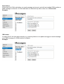
Automatic messages
Electricity failure
In case of electricity failure, an SMS can be sent only via the GSM module (description in the GSM module
manual).
Node failure
In the event of a CAN node failure, an email message can be sent, and with an installed GSM module an
SMS message can be sent. A CAN node failure is detected only after a time-out of 20 seconds.
Example:
CMI restart
A restart of the C.M.I. that was caused by e.g. electricity failure or an update can trigger an email message,
or an SMS message if a GSM module is installed.
Example:
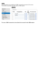
SMS
The designations and conditions for SMS commands are entered in this menu.
This function is possible only with a built-in GSM module.
The use of SMS commands is described in the manual for the GSM module.
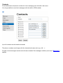
Contacts
E-mail addresses and phone numbers for text messaging are entered in this menu.
It is only possible to send text messages with the built-in GSM module.
Up to 8 contacts can be listed and tested.
The phone numbers must begin with the international area code (e.g. +44 ...).
E-mails or text messages can be sent to these contacts if the message condition (see menu “Messages”)
applies.
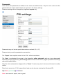
Passwords
User names and passwords for different user levels are defined here. Only the user name and the
password for the expert (admin/admin) are pre-set in the factory settings.
Password settings can be changed by registered experts only.
Passwords may not include special characters or umlauts ("ä, ü, ö").
Password entry must be repeated as a precaution.
The “Expert“ has complete access to the C.M.I. without restrictions.
The “User“ is authorised for access to the interactive online schematic and can view values and,
depending on the programming, also change them. Access to other C.M.I. pages is possible but settings
cannot be modified there.
Only the online schematic is displayed for a "Guest“. Guests may view it but are not allowed to modify
values.
Direct local access to a C.M.I. page without login can be done by entering the following URL:
http://user:password@cmi/xxxxxx
User: user name for expert, user or guest
Password: password defined for the respective user
cmi: host name or IP address of the C.M.I.
xxxxxx: entry of the required URL
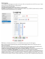
Data logging
The settings for data logging are made in this menu. Man can log either from the DL bus (max. 2 data
lines) or from the CAN bus (max. 8 data records).
The data is saved to the SD card.
Simultaneous logging from DL and CAN bus is not possible.
Example: CAN data logging of 2 data records each of node 1 (e.g. UVR1611) data record (or records)
node 2 (UVR16x2) and of node 40 (e.g. CAN-EZ)
1.
2.
Display of already used memory in % of available memory space for data logging.
The saving criterion defines the time interval for data logging. Entries from 10 seconds up to 60
minutes are possible.
3. Source information (DL bus: DL1, DL2 or CAN bus: entry of node number) and of the data record.
Controller UVR1611 and the CAN energy meter CAN-EZ can output 2 data records.
Please note during the logging of the data of controller UVR16x2: Depending on the settings in the
UVR16x2 menu CAN bus / data logging, only 1 data record or 2 data records are logged.
The number of data records depends on the following rule: If at least a higher or equal analogue value is
assigned to the number 17, then a 2nd data record is automatically created for this controller. The same
applies to digital values higher or equal to number 14. That is no apparent in the C.M.I. menu. If e.g.
4 UVR16x2 are entered, for which 2 data records each are output, then no additional data records are
displayed in Winsol even if they could be entered in the above list. Additional instruction for data logging
of controller UVR16x2 are in the programming manual of the controller.
4. Possibility to delete the internal memory of the C.M.I..
5. Possibility to delete the logged data on the SD card.
6. Creation of day log files on the SD card, which can be read with Winsol.
7. Completion of entry with “Save”.
8. Cancellation of entry and resetting to the setting saved last.
If the settings for the source and/or the data record of a source are changed, then we recommend
restarting the C.M.I. (menu “Ethernet/Restart“) and deleting the memory. After the first logging time,
a set-up is carried out in Winsol and completed with “Ok“ so that the C.M.I. logs data with the modified
settings.
The contents of the internal C.M.I. memory are saved to the SD card as a day log file every day at midnight.
During the readout with Winsol, a day log file is created for the current day and all day log files saved to
the SD card are copied into the monthly file of Winsol. Depending on the setting in Winsol, the daily log
files are either deleted or saved on the SD card.
With simultaneous data logging with C.M.I. and BL-Net or D-LOGG, this is not possible and will
disrupt logging.
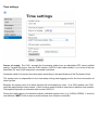
Time settings
Source of supply: The C.M.I. accepts the time-stamp either from an adjustable NTP server (default
setting: 3.at.pool.ntp.org) or from the CAN network (UVR1611 with node number 1) or via one of the two
data lines (DL bus) of the respective connected controllers.
Automatic switch to summer time takes place according to the specifications of the European Union.
The system time is responsible for the time-stamp during data logging and for the time information of
other log files.
Because the system time of all other devices will be accepted by node 1 in a CAN network, the C.M.I.
could be assigned with node number 1. But it must be ensured that no other device has this node number.
That applies especially to networks with several UVR1611.
During the data logging of controllers without individual system time (e.g. UVR64, HZR65), it must be
ensured that “WEB” is set as source and that there is an Internet connection.
Menu Status
This menu provides information above files saved to the SD card and other states of the C.M.I..
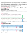
SD card
If an SD card other than the supplied one is used, then the following must be observed:
The SD card must be formatted with the FAT16 or FAT 32 file format.
# SD cards with a memory of up to 4 GB can be used without problems.
# SD cards with a memory of up to 32 GB can be used but the display of available memory may be
incorrect.
# SD cards with a memory of more than 32 GB cannot be used.
#
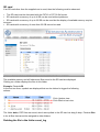
The available memory and all folders and files saved to the SD card are displayed.
Clicking on a folder displays the files in this folder.
Example: Folder LOG
In the first two lines, symbols are displayed that can be clicked to trigger the following
actions:
Click: Update view
Click: Back to last view
The folder doku, PDF files are saved, which were pulled to the SD card via drag & drop. Folder x-files
is for all files that cannot be assigned to other folders.
Deleting the file in the folder event_log
Clicking on this button deletes the txt file in the folder event_log (event and error memory).
Copy the SD card's files to the computer
Click on the file in question with the right mouse button and select the target on the computer.
TCP sockets
This page provides an overview of possible network connections and is especially helpful for experts
during the error analysis of network problems.
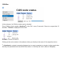
CAN-Bus
In this submenu, the CAN bus status can be checked.
1
Every CAN bus device sends a Heartbeat to the C.M.I. every 10 seconds. If there is no signal after 15
seconds, “Timeout“ is displayed for the node.
Example: Timeout of node 32
Clicking on the node number in this submenu takes you directly to the menu of the respective device.
1
A Heartbeat is a network connection between two (or more) computers in a cluster to inform each other
that they are operational and can still fulfil their tasks, i.e. that they are “alive” (Source: Wikipedia).
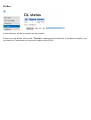
DL-Bus
In this submenu, the DL bus status can be checked.
If there is no signal after 15 seconds, “Timeout“ is displayed for the data line. In the above example, only
one data line is connected so a timeout is visible only with DL2.
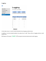
Logging
In this status menu, it can be checked whether the set logging method works.
In addition, it can be checked whether the system time is valid. There will be no logging without a valid
system time.
Brief lapses of the green “POWER“ LED at regular intervals indicates active data logging
CoE
This page shows the current data transfer "CAN over Ethernet" (CoE). More detailed explanations for
CoE can be found in chapter "Data transfer with CAN or Ethernet (CoE)”.
Data transfer with CAN over Ethernet (COE)
Description of the data transfer method
With this method it is possible to transmit analogue and digital CAN network variables via Ethernet (LAN,
only to a fixed IP address).
Data is transferred from one C.M.I. to one or several C.M.I., data can thus be exchanged between separate
CAN networks.
Parameterisation takes place via Excel table (coe.csv).
Data transfer via Ethernet takes place via UDP, port 5441.
Example:
Required settings
1. The receiver C.M.I. must have a fixed IP address. We recommend to first install the C.M.I. with DHCP
and to then deactivate the DHCP mode in the menu Settings/Ethernet.
If data is sent in both directions, both C.M.I.s must have a fixed IP address.
2. A csv file with the name coe.csv must be created for the transmitting C.M.I. precisely according
to the following setup (separator: semicolon ;). An empty sample file can be downloaded from the TA
website.
Note: The network in- and outputs of a CAN bus device have the numbers 1 to 32, whereby the digital
network in- and outputs are in the range 1 to 16 and the analogue ones are in the range 17 to 32.
Example: The analogue network output ANALOG 2 of the device has the number 18.
Example for the coe.csv file:
Column A
Nodes source
Specification of the node number of the CAN bus device
that the value to be transmitted originates from
Column B
Value source
Specification of the number of the network output of
this device. The digital network outputs always get the
number range 1 to 16, the analogue ones 17 to 32.
Column C
Send as node
Column D
Send as value
Column E
To IP
The receiving C.M.I. gets this virtual node number in
addition to its own number. This virtual node number
must not already be assigned in the CAN-network of the
receiving C.M.I. Several virtual node numbers can be
assigned for one C.M.I.
The transmitted value gets this number for the network
output. Here too, the digital values must get a number
between 1 and 16 and the analogue values a number
between 17 and 32.
This is the fixed IP address of the receiving C.M.I.
A maximum of 128 values can be entered in this table and transmitted via LAN.
The values can be from the network output of each CAN bus device (UVR1611, CAN I/O, CAN-EZ, CANBC, CAN-MT).
In the example above, two analogue values (17, 18 = ANALOG 1 and 2)) and one digital value (1 =
DIGITAL 1) are transmitted from node 1 and one analogue value (17 = ANALOG 1) is transmitted from
node 2 via the C.M.I. of the source network.
The receiving C.M.I. of the other CAN network has the IP address 192.168.10.253.
The virtual node numbers of this C.M.I. are 50 and 45 here.
Important instructions for the use of more than 2 C.M.I.s for the data
transfer via Ethernet:
Analogue network outputs
The analogue network outputs of a controller are sent in blocks to 4 NW outputs each into the CAN bus
network (17-20, 21-24, 25-28, 29-32) and stored by the other side.
Analogue signals from 2 different C.M.I.s may therefore not be sent to the same block of the same virtual
node on the receiver C.M.I.
Example:
Incorrect parameterisation:
C.M.I. 1 sends two values to the C.M.I. 3 via the virtual node 50 to the first block
Nodes source
Value source
Send as node
Send as value
To IP
1
17
50
17
192.168.10.253
1
18
50
18
192.168.10.253
C.M.I. 2 sends two values to the C.M.I. 3 via the same virtual node 50 and also to the first block
Nodes source
Value source
Send as node
Send as value
To IP
1
17
50
19
192.168.10.253
1
18
50
20
192.168.10.253
Each time values are now sent from C.M.I. 1 to C.M.I. 3, the values to be received from C.M.I. 2 are set
to 0 and vice versa.
Correct parameterisation for C.M.I. 2:
The values from C.M.I. 2 to C.M.I. 3 must be output either via another virtual node or via the values of
another block:
Nodes source
Value source
Send as node
Send as value
To IP
1
17
51
17
192.168.10.253
1
18
51
18
192.168.10.253
Nodes source
Value source
Send as node
Send as value
To IP
1
17
50
21
192.168.10.253
1
18
50
22
192.168.10.253
or:
Digital network outputs
The same applies to digital network outputs: These are sent in one complete block for all 16 values into
the CAN bus network and accepted by the other side.
Digital signals from two different C.M.I.s may therefore not be sent via the same virtual node of the receiverC.M.I.
Example:
Incorrect parameterisation:
C.M.I. 1 sends two values to C.M.I. 3 via virtual node 50
Nodes source
Value source
Send as node
Send as value
To IP
1
1
50
1
192.168.10.253
1
2
50
2
192.168.10.253
C.M.I. 2 sends two values to C.M.I. 3, also via virtual node 50
Nodes source
Value source
Send as node
Send as value
To IP
1
1
50
3
192.168.10.253
1
2
50
4
192.168.10.253
Each time values are now sent from C.M.I. 1 to C.M.I. 3, the values to be received from C.M.I. 2 are set
to 0 (OFF) and vice versa.
Correct parameterisation for C.M.I. 2:
The values from C.M.I. 2 to C.M.I. 3 must be output via another virtual node.
Nodes source
Value source
Send as node
Send as value
To IP
1
1
51
1
192.168.10.253
1
1
51
2
192.168.10.253
3. The csv file coe.csv must now be copied to the root directory of the SD card of the transmitting C.M.I.
If the file is copied to the SD card with drag & drop, then it is automatically stored in the root folder.
4. After the copy process, the C.M.I. must be. restarted (menu “Settings/Ethernet“) for the csv file to
be loaded. Correct loading of the units requires a complete system reboot.
5. The transfer connection is now set up and the data is transmitted according to the transmit
conditions of the node that the values originate from.
6. The values that are output as CAN output variable by the virtual node of the receiving C.M.I., can now
be accepted as CAN input variable by any CAN bus member of the CAN network in which the receiving
C.M.I. is. The values are sent according to the transmission conditions of the CAN bus devices in the
network of the transmitting C.M.I.
Example: Menu NETWORK / INPUT VARIABLE / ANALOG
The controller accepts the values of the network outputs ANALOG 1 and 2 (17 and 18) of virtual node
50 on the network inputs ANALOG 1 and 2. This menu does not show units and decimal places.
As soon as the first value has been transmitted by the transmitting C.M.I., the virtual node (only directly
on the controller) will be visible as an active node in the menu Network/Network nodes. This active node
should but not be selected though. This mode is not visible in the browser view of the C.M.I.
These two analogue network inputs can be seen under 17/18 (also in the browser) in the menu Measured
st
values overview. The corresponding unit is displayed only after the 1 data transmission of the measured
value.
EC-DECLARATION OF CONFORMITY
Guarantee conditions, Legal notice
Guarantee conditions
Note: The following guarantee conditions do not in any way limit the legal right to a guarantee; rather
expand your rights as a consumer.
1. The company Technische Alternative elektronische Steuerungsgerätegesellschaft m. b. H. provides a two-year
guarantee from the date of purchase by the end consumer for all the devices and parts which it sells. Defects
must be reported immediately upon detection and within the guarantee period. Technical support knows the
correct solution for nearly all problems. In this respect, contacting us immediately will help to avoid unnecessary
expense or effort in troubleshooting.
2. The guarantee includes the free of charge repair (but not the cost of on site fault-finding, removal, refitting and
shipping) of operational and material defects which impair operation. In the event that a repair is not, for reasons
of cost, worthwhile according to the assessment of Technische Alternative, the goods will be replaced.
3. Not included is damage resulting from the effects of overvoltage or abnormal ambient conditions. Likewise,
no guarantee liability can be accepted if the device defect is due to: transport damage for which we are not
responsible, incorrect installation and assembly, incorrect use, non-observance of operating and installation
instructions or incorrect maintenance.
4. The guarantee claim will expire if repairs or actions are carried out by persons who are not authorised to do so
or have not been so authorised by us or if our devices are operated with spare, supplementary or accessory parts
which are not considered to be original parts.
5. The defective parts must be sent to our factory with an enclosed copy of the proof of pur-chase and a
precise description of the defect. Processing is accelerated if an RMA number is applied for via our home page
www.ta.co.at. A prior clarification of the defect with our technical support is necessary.
6. Services provided under guarantee result neither in an extension of the guarantee period nor in a resetting of
the guarantee period. The guarantee period for fitted parts ends with the guarantee period of the whole device.
7. Extended or other claims, especially those for compensation for damage other than to the device itself are,
insofar as a liability is not legally required, excluded.
Legal notice
These assembly and operating instructions are protected by copyright.
Use outside the copyright requires the consent of the company Technische Alternative elektronische
Steuerungsgerätegesellschaft m. b. H.. This applies in particular to reproductions, translations and electronic media.
Subject to technical modifications
© 2015
This website uses Google Analytics, a web analytics service provided by Google, Inc. Google Analytics uses socalled “cookies”, text files, which are stored on the computer of the customer and which enable analysis of the
utilization of the website. The information generated by the cookie about the use of the website (including the
user IP address) will be transmitted to and stored by Google on servers in the United States. Google will use this
information for the purpose of evaluating the use of the website, compiling reports on website activity for website
operators and providing further services relating to website use and Internet use. Google may also transfer this
information to third parties where required to do so by law, or where such third parties process the information on
Google's behalf. Google will in no case associate your IP address with any other data held by Google. You may
prevent the use of cookies by selecting the appropriate settings on your browser; however, we would like to point
out that you will in this case not be able to make use of all the functions of this website. By using this website, you
consent to the processing of data about you by Google in the manner and for the purposes set out above.
Technische Alternative
elektronische Steuerungsgerätegesellschaft m. b. H.
A-3872 Amaliendorf Langestraße 124
Tel +43 (0)2862 53635
Fax +43 (0)2862 53635 7
E-Mail: [email protected]
--- www.ta.co.at ---
© 2015