1
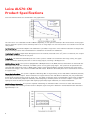
Leica ALS70-CM
City Mapping Airborne LIDAR
Product Specifications
Leica ALS70-CM
Product Specifications
Overview
ALS70-CM is a compact laser-based system designed for the acquisition of high-density topographic and return signal intensity data from a variety of airborne platforms, at flying heights up to 1600 m AGL. The data is computed using range and
return signal intensity measurements recorded in flight along with position and attitude measurements from an airborne
GNSS/inertial subsystem. The ALS70-CM falls into the category of airborne instrumentation known as LIDAR (LIght Detection
And Ranging). This document establishes the minimum requirements for the ALS70-CM, referred to as “the system” herein.
Basic Design
Operating Principle: By measuring the location (latitude, longitude and altitude) and attitude (roll pitch and heading) of the
aircraft, the distance to ground and scan angle (with respect to the base of the scanner housing), a ground position for the
impact point of each reflected laser pulse can be determined.
What is included: The system is a turn-key airborne LIDAR mapping system and includes all required airborne equipment
needed for system operation. The system includes all post-processing software necessary to produce latitude / longitude /
elevation / intensity output, and this software is designed to process output for a wide variety of ALS40, ALS50, ALS60 and
ALS Corridor Mapper and ALS70 configurations.
What is not included: The user normally supplies the following:
•
•
•
•
•
Survey grade dual-frequency GNSS base station, or equivalent accuracy reference station source
Mission planning and post-processing computers (a high-end PC – see separate Technical Note)
Data archiving hardware/software
Aircraft, modified as needed, including appropriate power outlet
Aircraft power outlet mating plug
Accessories
Ground Power Supply: The system normally operates on 28 VDC. For ground operations, the PS56 Ground Power Supply is
provided which allows operation of the system from standard AC (110/220 VAC) mains.
Download Station: A Download Station Assembly allows data transfer between the MM70 in-flight storage media to the
user’s computer system via USB connection.
Standard Components
The system consists of the following physical assemblies:
•
•
•
•
•
•
•
LS70-LP Scanner Assembly
System Electronics (LC60 Laser Controller + SC70-CM System Controller)
OC52 Operator Interface
OC50 Pilot Interface
Vibration-isolated interface plate assemblies for both scanner and electronics
GNSS + GLONASS antenna
Interconnecting cables
LS70-LP Scanner Assembly
The Scanner Assembly produces controlled movement of the transceiver aim point by galvanometer actuation of a scan
mirror. The aim point of the laser output (relative to the scanner housing) is measured by a high accuracy optical angle
encoder. The scanner is a sealed, desiccated volume with a rigid optical window. The following major components form the
Scanner Assembly.
2
Leica ALS70-CM
Product Specifications
Laser Transmitter (part of LC60 Laser Controller): The laser transmitter produces output laser pulses using a diodepumped transmitter. It also contains an optical trigger output, shutter, and beam expansion/collimating optics that bring the
dual laser outputs to the scan mirror.
Receiver: The receiver collects a sample of the laser output pulse and detects laser pulses reflected by terrain below
the aircraft.
Scanner Mechanization: A high-performance galvanometer scanner is used to actuate the scan mirror.
Mirror and Window Assembly: Standard systems are shipped with a large-aperture low-inertia/high-speed scan mirror optimized for fields of view up to 75 degrees at altitudes to 3500 m AGL (in SPiA mode), allowing upgrade of the system to
ALS70-HP configuration.
Digital Camera: An XGA-resolution (1280 x 1024 pixel) digital camera is included in the scanner. This integrated camera
allows a real-time view of the terrain below the aircraft, as well as providing recorded images at fixed intervals. The recorded images contain embedded annotation data. Leica LCam Viewer software allows the user to search for a particular frame
by GNSS time, enabling selection of the appropriate frame for any given portion of the LIDAR mission, and accesses the
embedded annotation data in order to provide automatic north-up image orientation. Zoom functions are also provided.
Interface plate: A vibration-isolated interface plate is provided to allow Scanner Assembly mounting to aircraft. Specific
interface plate selection will depend on installation type (pod versus in-cabin and standard versus low-profile mounting) and
auxiliary sensor usage.
System Electronics
The System Electronics assembly contains assemblies responsible for subsystem coordination, raw data measurement and
data recording. The following major components make up the System Electronics:
SCM70-CM System Controller Module: The System Controller Module controls laser operation, measures range to ground
via the high-speed time interval counter, measures the intensity of reflected return signals, generates electrical signals
needed to direct the optical scanner, reads the encoded scan angle, reads GNSS timing information and formats all these
data for recording on a high-speed data logger.
IPAS20 Inertial Position and Attitude System: This subsystem provides and records master timing and aircraft position/attitude information using a GNSS receiver, a high-accuracy IMU (mounted inside the scanner housing) and an integral
processor. The IPAS subsystem records data via an Ethernet connection to the DLM65 Data Logger Module.
GCM60 Galvanometer Controller Module: The Galvanometer Controller Module provides drive current to the scanner assembly’s galvanometer by comparing a commanded scan position signal (provided by the System Controller Module) to the
galvanometer’s actual position (provided by the galvanometer’s position detector).
DLM65 Data Logger Module: The Data Logger Module stores output from both system controller and IPAS modules, including GNSS timing and position, unprocessed IMU data, range, return signal intensity, synchronization data and scanner position information, for later processing. The data is stored on a removable solid state disc drive (SSD). Four removable SSDs
are supplied with the system, one in the SC70-CM System Controller and 3 additional SSDs for rotation from the field back
to the processing center.
LC60 Laser Controller: The Laser Controller provides power conditioning, control and optical pump energy for the laser
head (located inside the Scanner Assembly).
PDM60 Power Distribution Module: The power distribution module provides reverse polarity protection, conducted EMI
suppression and power connections to each SC70-CM functional module from a single DC input, as well as providing regulated DC power for the OC52 or OC50 operator and pilot interface and the LS70 Laser Scanner.
3
Leica ALS70-CM
Product Specifications
OC52 and OC50 Operation Controllers
The OC52 and OC50 provide airborne-qualified, outdoor-readable display platforms for operator interface and flight navigation software, respectively. The operator interface software provides a graphical user interface for system setup, operation,
monitoring and flight navigation.
OC52 Operation Controller: Primary input to the operator interface software is via the OC52’s large touch-screen display
and compact weather-proof keyboard. Both the OC52 display unit and the compact keyboard are mounted to a rugged
bracket that provides optimal viewing angles for both display and keyboard. The bracket provided allows mounting on horizontal or vertical surfaces, or on the optional IS40 pedestal or PHT50 holder.
OC50 Operation Controller: The primary navigation display for the system is the OC50. The compact display with “hot
keys” allows ready switching between available navigation views.
Software
The following software is included with the system:
AeroPlan70: This proprietary mission planning template is a subset of Leica FPES Flight Planning and Evaluation Software
and is provided to aid users in determining proper system set-up and flight line spacing.
Flight Planning and Evaluation Software (FPES): Calculates optimal flight line layout and embeds layout and optimized
system settings in a flight plan database file for transfer to system.
Flight and sensor Control Management Software (FCMS): Accepts flight plan database files from FPES and provides aided
navigation for pilot and automatic or manual system operation for the system operator.
IPAS-TC GNSS/IMU Processing Software: Combines GNSS base station data with IPAS airborne GNSS data to provide a
DGNSS aircraft position solution; combines the DGNSS solution with Scanner Assembly IMU data to provide smoothed position and orientation data. Post processed output features a “tightly-coupled” solution, allowing steep bank angles during
turns. This software also allows download of real-time (non-differentially corrected) position and orientation data for
“quick-look” processing.
ALS Post Processor (ALSpp): Assembles trajectory output from GNSS/IMU processing software with raw scanner files into a
master data file and processes the master data file into a ground coordinate point cloud including latitude, longitude, elevation and intensity values. File output is in a variety of projections including WGS84 and UTM as well as in a variety of formats, including:
•
•
•
•
ASCII XYZ in WGS84 and UTM coordinates worldwide, as well as state-plane coordinates in the USA. All coordinate
conversions are compatible with CORPSCON
LAS (LAS 1.2 for standard discrete-return data and LAS 1.3 for full-waveform data)
User-required custom projections or geoid corrections. Customers can provide the mathematical definitions for custom projections and/or geoid models to Leica Geosystems for incorporation into ALSpp
Gray-scale intensity image output (i.e., x/y/intensity images in *.tif format)
Optional Components
WDM65 Waveform Digitizer Module: Allows capture of full waveforms from returned pulses. WDM65 is integrated into the
SC70-CM System Controller and allows parallel operation in both waveform collection and discrete-return range measurement modes.
IS40 Stand: Provides a pedestal on which to mount OC52 or OC50 displays.
PHT50 Adapter: Allows mounting of OC52 or OC50 displays to IS40 stands already having another display attached.
4
Leica ALS70-CM
Product Specifications
GI40 Guidance Indicator: The compact GI40 Guidance Indicator provides a small dashboard-mounted course deviation indicator. The GI40 can be used in addition to the OC50 Pilot Display for a more succinct “heads-up” display. It can also be
used in place of the OC50 Pilot Display if available cockpit space is limited. The GI40 features a blue LED display meeting
worldwide illumination color requirements.
Technical Specifications
Critical Item Definition
The system consists of all hardware and software necessary to meet the specifications herein. All assemblies are designed
for rugged environments sustained on unpressurized light aircraft. As such, the system is capable of operation while being
subjected to variations in temperature, humidity and altitude experienced in flight. In addition, surfaces of the system exposed during flight are capable of operation during exposure to precipitation and blowing dust.
Physical Requirements
Size: The system is within the following envelope dimensions, as shown in drawings 766097 (Integration Drawing, LS70-LP
Scanner w/o RCD), 766098 (Integration Drawing, LS70 Scanner w/ front-mount RCD) and 766099 (Integration Drawing,
SC70/LC60). The standard configuration for the System Electronics is a "rackless" 8U-tall assembly on a vibration-isolated
interface plate assembly. Mounting provisions are available on the top and bottom of the front and rear panel handles of
the System Electronics for users wishing to install additional equipment (e.g., the CC105 Camera Controller for RCD105 or
CC31 Camera Controller for RCD30). The standard low-profile interface plate 771406 can be used to allow vibration-isolated
mounting of the scanner plus up to 2 CH39 camera heads, while the 785696 low-profile interface plate assembly allows
installation of either a single CH39 or single CH6x camera head.
Scanner Assembly Dimensions (all IMUs):
Length (no handles, no interface plates)
Length (parallel to flight direction, with handles, no interface plate)
Length (no handles, on 771406 isolated interface plate assembly)
Width (no interface plate)
Width (on 771406 isolated interface plate assembly)
Height (no interface plate)
Height (on 771406 isolated interface plate assembly)
23.68”
26.68”
32.98”
14.50”
19.52”
10.05”
10.05”
(602 mm)
(678 mm)
(838 mm)
(369 mm)
(496 mm)
(255 mm)
(255 mm)
24.50”
17.63”
19.52”
14.00”
16.14”
(622 mm)
(448 mm)
(495 mm)
(356 mm)
(410 mm)
System Electronics Dimensions:
Depth (including handles, cabling)
Width (bare stack)
Width (on 754141 isolated interface plate assembly)
Height (bare stack)
Height (on 754141 isolated interface plate assembly)
Operator Interface (OC52 + keyboard):
Depth (keyboard horizontal)
Width
Height (keyboard horizontal)
9.13” (232 mm)
11.89” (302 mm)
10.12” (257 mm)
Weight:
The maximum weight of system components is as follows:
Scanner (max, with CUS6 IMU, incl. IMU, main cables)
Scanner (on 771406 isolated assembly, lo pro for LS + 2x CH39)
Scanner (on 753564 isolated assembly for LS only)
92.6 lb (42.1 kg)
~110.0 lb (50.0 kg)
111.1 lb (50.5 kg)
5
Leica ALS70-CM
Product Specifications
Scanner (on 756791 isolated assembly for LS + 2x CH39)
System Electronics (incl. LC60 cable, no interface plate)
System Electronics (on isolated interface plate ass’y)
OC52 Operation Controller (with keyboard, bracket)
OC50 Pilot (745210)
OC52 Cable (Qty2)
Total (typical, on 761406)
129.8 lb (59.0 kg)
104.5 lb (47.5 kg)
111.6 lb (50.7 kg)
7.8 lb (3.6 kg)
3.3 lb (1.5 kg)
1.8 lb (0.8 kg) each
236.3 lb (107.4 kg)
Notes: Subtract approximately 5.6 lb (2.6 kg) for systems equipped NUS5 IMU
Subtract approximately 7.5 lb (3.4 kg) for systems equipped DUS5 IMU
Mounting
Scanner Assembly: The Scanner Assembly is mounted to the aircraft using the included vibration-isolated interface plate.
Mounting features are shown in drawings 766097 (Integration Drawing, LS70-LP Scanner w/o RCD), 766098 (Integration
Drawing, LS70-LP Scanner w/ front-mount RCD) and 766099 (Integration Drawing, SC70/LC60). All mounting surfaces are
black anodized per MIL-A-8625 TY II CL 2 to resist corrosion. The default vibration-isolated interface plate assembly
(753564) allows Scanner Assembly mounting directly to aircraft already equipped to accept Leica/LH Systems/Wild PAVseries or other stabilized camera mounts. The Scanner Assembly is designed so that no structures protrude below the aircraft floor.
System Electronics: The System Electronics are normally mounted using the included vibration isolated interface plate assembly. Optional mounting “wings” are available as an accessory to allow installation of system electronics in EIA-standard
19-inch racks.
Operator Interface: The Operator Interface is designed for mounting to sturdy horizontal or vertical surfaces, to the optional IS40 mounting pedestal or to the optional PHT50 Holder. Mounting for this assembly should be provided by the user
in an appropriate fashion to minimize strain on the high-density electrical connectors used for interface between the System Controller and the OC52 Operation Controller, and to minimize movement of the assembly or cables when exposed to
atmospheric turbulence during flight.
Environmental Requirements
Specification
6
Reference to Standard / Environmental Test Index
Operating Temperature and Altitude
RTCA DO-160F, Section 4, Cat B1, Max 40 C up to 2000 m AMSL or equivalent cabin pressure,
then declining at 6.6 C per 1000 m to max 26.8 C at 4000 m AMSL or equivalent cabin
pressure, then constant at max 26.8 C to 25000 feet (7620 m) AMSL or equivalent pressure,
minimum 0 C at all altitudes.
Storage Temperature
RTCA DO-160F, Section 4, Cat B1, -55 to +85 C
Temperature Variation
RTCA DO-160F, Section 5, Cat B
Humidity
RTCA DO-160F, Section 6, Cat B, 0 - 85% RH
Operational Shocks and Crash Safety
Level 2 for all Fixed-Wing Aircraft
Types and Helicopter
RTCA DO-160F, Section 7, Cat E (FAR 27.561), 20g
Vibration
RTCA DO-160F, Section 8, Cat S
Magnetic Effect
RTCA DO-160F, Section 15, Cat B
Power Input
RTCA DO-160F, Section 16, Cat B
Leica ALS70-CM
Product Specifications
Voltage Spike
RTCA DO-160F, Section 17, Cat A
Audio Frequency Conductive
Susceptibility – Power Inputs
RTCA DO-160F, Section 18, Cat B
Induced Signal Susceptibility
RTCA DO-160F, Section 19, Cat BC
Radio-Frequency Susceptibility
(Radiated and Conducted)
RTCA DO-160F, Section 20, Cat RR
Emissions of Radio Frequency Energy
RTCA DO-160F, Section 21, Cat M
Lightning Induced Transient
Susceptibility
RTCA DO-160F, Section 22, Cat A3E3X
Insulation Resistance and High
Voltage
RTCA DO-160F, Section 25, Cat A
Performance Requirements
Slant Range: The recommended maximum slant range for the system is approximately 1848 m (see graph describing maximum pulse rate for given flying height and SPiA/MPiA configuration). Systems can not be operated at longer slant ranges,
unless upgraded to ALS70-HP configuration. Recommended minimum slant range is 200 m.
Field of View (FOV): System FOV is adjustable over the range of 0-75 degrees, in 1-degree increments. Contact Leica Geosystems for inquiries regarding maximum unvignetted FOV for installation in specific aircraft.
Scan Pattern: The system provides 3 scan patterns, all in a plane nominally orthogonal to the longitudinal axis of the scanner, nominally centered about nadir:
•
•
•
Sinusoid scan:
Triangle scan:
Raster scan:
with data collection on both left-bound and right-bound scans
with data collection on both left-bound and right-bound scans
with unidirectional scanning
Scan Rate: Maximum scan rate degrades as a function of increasing FOV. Maximum scan rates (in Hz) as a function of FOV
(in degrees, full angle) are defined in the following table:
Scan Pattern
5
Sinusoid
Triangle
Raster
Absolute Maximum
(Hz)
Maximum scan rate function
(Hz)
4
-2.11161387594222E-08 FOV + 2.39640751412990E-05 FOV - 4.85238584953128E3
03 FOV
2
+ 3.90365933090094E-01 FOV – 1.51874883452176E+01 FOV +
3.53112587418088E+02
- 1.28635419945581E+00 FOV + 1.58293326854730E+02
3
2
- 3.65199025243180E-04 FOV + 5.91996857602394E-02 FOV
– 3.61365678536448E+00 FOV + 1.20188139776174E+02
200 Hz
158 Hz
120 Hz
7
Leica ALS70-CM
Product Specifications
Scan rate maximum limits are summarized in the graph below:
The scan rate is user-selectable from 0 to 200 Hz (depending on scan pattern selected) in 0.1 Hz increments via the graphical user interface. System control software prevents out-of-range inputs for scan rate based on user selection for FOV and
scan pattern.
Roll Stabilization: Automatic adaptive roll stabilization is provided. Any portion of the maximum accessible 75-degree FOV
that is not being used for the commanded FOV is available for automatic roll stabilization.
2
Illuminated Footprint: Output beam divergence is 0.22 mr nominal, measured at the 1/e point. For reference, this is equivalent to 0.15 mr measured at the 1/e point.
Pulse Rate: The maximum achievable pulse rate of the system is related to the maximum slant range setting. The graph
below summarizes maximum pulse rates at various flying heights, assuming a 40-degree FOV.
Multiple Pulses in Air: The system is equipped with a Multiple Pulses in Air (MPiA) feature, which allows an increased maximum pulse rates over that offered by non-MPiA systems for any given flying height. The system can be operated in conventional SPiA (Single Pulse in Air) or MPiA modes, and the range accommodation envelope (maximum slant range minus
minimum slant range) is the same in both MPiA and SPiA modes. Maximum achievable pulse rate in each mode is shown in
the graph below.
Target Detection Rate: The system is capable of detecting 90% of targets having at least 10% diffuse reflectivity and fully
intercepting the laser footprint. Return reflection for targets with less than 10% diffuse reflectivity may not produce adequate signal strength and may result in “drop-outs”. The ability to measure range associated with a given return is dependent on the surface having adequate reflectivity and intercepting a sufficient portion of the laser footprint. Targets intercepting less than the full laser footprint will require proportionally higher reflectivity for successful detection.
Multiple Target Detection: The system is capable of detecting an unlimited number of returns for each outbound laser
pulse, provided each reflecting surface results in adequate signal strength for detection. Vertical discrimination distance is
approximately 3.5 m.
8
Leica ALS70-CM
Product Specifications
Multi-Return Intensity: Systems are shipped with a multiple-return intensity measurement feature. With this feature, the
sizes of the reflected returns at various elevations (up to the first three returns from each outbound pulse) are measured in
addition to the distances to each reflecting surface measured by the range counting cards. An 8-bit scale is used. The ability
to digitize the signal strength is dependent on the surface having adequate reflectivity and intercepting a sufficient portion
of the laser footprint. Targets intercepting less than the full laser footprint will require proportionally higher reflectivity for
successful detection.
AGC Setting Capture: The system digitizes the AGC value being used during detection of each return. An 8-bit scale is used.
The captured AGC value can be used in combination with a Gain-Based Intensity Correction (GBIC) table to produce highquality intensity images even while the system automatically adjusts detection sensitivity to optimal levels for accurate
range measurement.
Accuracy: The system produces data after post processing with a lateral placement accuracy of 5 – 38 cm and vertical
placement accuracy of 7-16 cm (one standard deviation) from full-field-filling targets of 10 percent diffuse reflectivity or
greater with atmospheric visibility of 23.5 km or better for flying heights up to 3500 m AGL (SPiA mode) and nominal FOV of
40 degrees. Accuracy estimates for particular mission profiles (i.e., flying height above terrain and position within FOV) are
shown below and can be provided in detail by using the AeroPlan70 mission planning template. Estimates below are made
assuming a 40-degree FOV, DUS5 or CUS6 IMU and a nominal 5 cm GNSS error.
Side Lobes: The laser output beam does not have any side lobes outside the main beam.
Input Voltage: See “Environmental Requirements”.
Input Power: The system is designed to minimize damage due to out-of-range supply voltage. Maximum average power
draw is 937.2 Watts without the FWD option and 972.4 Watts with the FWD option.
Reverse Polarity Protection: The system is designed to sustain accidental exposure to reverse polarity applied to the main
power input. The system will not operate under such a condition.
Laser Output Control: The system provides control over laser output over an approximate 100:1 range.
Beam Uniformity: The ratio of the laser’s peak beam intensity to average beam intensity should not exceed 4:1.
Warm-Up Time: The system is ready for use within 10 minutes of application of primary power.
Duty Cycle: The system is capable of continuous operation at maximum pulse rate. Recording capacity is defined below.
9
Leica ALS70-CM
Product Specifications
Design Requirements
Laser Output Shutter: The system has an integrated shutter allowing full output or complete obscuration of the output
laser beam. The assembly is remotely actuated using the graphical user interface software. The assembly provides status
signals to the system controller sufficient to allow confirmation of assembly position (closed or open).
Emission Indicator: A CDRH-compliant laser emission indicator is provided on the underside of the Scanner Assembly. When
the Scanner Assembly is installed in the aircraft, the emission indicator is readily visible from points below the scanner output window.
Warning Buzzer: A CDRH-compliant audible warning indicator is incorporated into the Scanner Assembly.
Sighting Window: A sighting window is provided on the Scanner Assembly. The sighting window allows the user to view the
condition of the scanner output window from inside the aircraft for evidence of fogging, icing or gross contamination. The
sighting window provides high visible light transmission while providing attenuation of 1064 nm laser energy with an optical
density of 6.0 or greater.
OS Installation: Non-mechanical drive
OS Protection: Protected from improper shutdown via EWF on Windows XPe
Data Storage: Removable SSD (MM70)
Recording Capacity: The system has a nominal recording capacity of approximately 6.0 hours on single MM70 Mass Memory
when operating at maximum pulse rate. Capacity is proportionally longer at lower pulse rates. Capacity is lower when using
optional WDM65 Waveform Digitizer module and also depends on waveform rates and/or waveform size. Data drives can
be swapped in flight, after system shut-down, re-start and in-air GNSS/IMU initialization.
Built-In Test (BIT): The system has a BIT mode that provides simulated multiple-return target signals to the range finding
subsystem. These signals allow system self-test of all range processing circuits.
Circuit Breakers / Fuses: Circuit breakers or fuses are provided to fuse primary power or limit damage due to an electrical
fault inside major subassemblies. The primary (mains) breaker is a 50A magnetic-type breaker for accurate operation over a
variety of ambient temperatures.
Hazardous Voltage Exposure: When the system is installed in the aircraft, no exposure to potentially harmful voltages is
possible.
Electrical Connectors: Connectors will not disconnect or become loose under the environmental conditions specified elsewhere in this document during the service life of the equipment. All connectors are keyed and/or labeled where needed to
prevent damage due to improper mating.
Strain Relief: Interconnecting cables connected to the System Controller are restrained by two clamping assemblies on the
System Controller rear handle in order to prevent damage. An integral strain relief is provided where the main cable bundle
enters the Scanner Assembly. Retention for the remaining portions of the interconnecting cables must be installed by the
end user in such a fashion as to prevent a tripping hazard in the aircraft.
Pressure Relief: The Scanner Assembly features a pressure relief valve to prevent pressure or vacuum build-up of more
than 0.5 PSI (differential).
Desiccation: The Scanner Assembly has provisions for a disposable desiccant packet to remove moisture from any air entering the scanner housing via the relief valve. Desiccation is adequate to prevent fogging or condensation on the interior of
the scanner housing when operated in the environments specified elsewhere in this document.
Post Processing Software: Software is provided which processes raw data collected in the air and on the DGNSS base station and produces an output data set in WGS84 coordinates. Industry standard LAS format is used for output of the post
processed data. Post processing software is designed to run under all Microsoft Windows operating systems XP and higher.
10
Leica ALS70-CM
Product Specifications
Documentation
Test Report: Each system is supplied with an outgoing test report. Unless otherwise specified, all data are provided at maximum pulse rate. The test report provides at least the following information:
•
•
•
•
•
•
•
2
Beam diameter (1/e and 1/e , nominal), at the exit aperture of the beam expander
2
Beam divergence (1/e and 1/ e , nominal)
Pulse width (Full Width Half Max)
Maximum single-pulse energy
Emitted wavelength
IMU offset (boresight) settings
Encoder and range calibration offsets, including IBRC and GBIC files
User Documentation: A User Manual is provided with the delivered system. This documentation includes the following:
•
•
•
•
•
•
•
System Description
Installing the System
Care and Handling
System Operation
Safety Directions
Technical Data
Warranty - Software License Agreement
Proprietary information is supplied at the discretion of Leica Geosystems. All technical data shall remain proprietary to Leica
Geosystems and is provided for the sole purpose of assisting in system usage and maintenance.
Upgrade Availability
Upgrades are available from all ALS60 configurations, including ALS Corridor Mapper (ALS60 generation) to all ALS70 configurations. Upgrade information is provided below. ALS50-II and earlier systems (including ALS50-II generation Corridor Mapper systems) cannot be upgraded to any ALS70 configuration.
FWD-ready ALS60 to ALS70-CM: Available as factory/Service Center upgrade (consult factory for ordering information)
Non-FWD-ready ALS60 to AL70-CM: Available as factory/Service Center upgrade (consult factory for ordering information)
FWD-ready ALS60-CM to ALS70-CM: Available as factory/Service Center upgrade (consult factory for ordering information)
Non-FWD-ready ALS60-CM to ALS70-CM: Available as factory/Service Center upgrade (consult factory for ordering information)
ALS70-CM to ALS70-HP: Available as on-site upgrade (consult factory for ordering information)
Training, Support and Maintenance
Training: Systems include three (3) one-week training sessions at the customer’s site to support installation, operator
training and processing technician training. Additional training support is available on a fee-for-service basis.
Warranty: One year on system and peripheral components.
Customer Care Packages (CCPs): An extended support program including provisions for replacement parts and labor can be
purchased. Extended warranty provisions do not cover desiccant replacement and/or customer-damaged items.
11
Whether you want to capture airborne data of an agricultural area
or of a city, record the challenges in a disaster area or the expanse of
a high tension line, you need reliable measurements and solutions for
your entire workflow to build image-based maps. Leica Geosystems’
broad array of airborne sensors and integrated software solutions
capture data efficiently, reference imagery accurately, measure easily,
analyze and present spatial information in 3D.
Those who use Leica Geosystems products every day trust them
for their precision, their seamless integration and their superior
customer support. When data really counts, Leica Geosystems delivers
geospatial imaging solutions with precision, integration and service.
When it has to be right.
Illustrations, descriptions and technical specifications are not binding and may change.
Printed in Switzerland – Copyright Leica Geosystems AG, Heerbrugg, Switzerland, 2008.
785443en – I.12 – RDV
Leica Geosystems AG
Heerbrugg, Switzerland
www.leica-geosystems.com