1
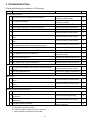
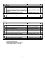
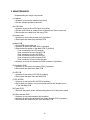
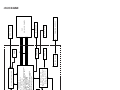
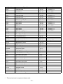
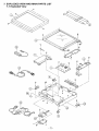
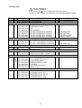
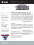
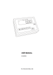
SERVICE MANUAL
INDUSTRIAL MONITOR
LMU-TK15C4
(GENERAL)
PRODUCT CODE No.
LMU-TK15C4
1 938 102 49
REFERENCE NO. SM 920011
INDEX
Page
2
PRECAUTIONS
1, MAIN SPECIFICATION
3
2, TROUBLE SHOOTING
4,5
3, MAINTENANCE
Disassembling the major components
6
4, BLOCK DIAGRAM
7
5, CONNECTION DIAGRAM
8
6, TABLE OF SIGNAL NAME
9,10
7, EXPLODED VIEW AND PARTS LIST
7-1 Exploded View
11
7-2 Parts List
12
8, APPENDEX
13
Refer to the separate volume user's guide for instruction.
-1-
PRECAUTIONS
Placement precautions
l
Avoid placing the unit in humid or dusty places, or where it will be exposed to excessive heat
(direct sunlight, heaters, etc.)
l
Do not step on or set anything on the AC cord.
DAMAGE TO THE AC CORD IS A SAFETY RISK AND CAN CAUSE A FIRE.
l
Do not connect the unit to the same AC as outlet with appliances that generate large amounts of
interference (such as heaters with thermostats, appliances with motors, etc.). It is best to use a
completely separate electrical outlet.
l
Keep the unit away from water. If water accidentally enters the unit, unplug the AC power cord
immediately. DO NOT PLUG IN THE UNIT AGAIN.
Handling precautions
l
Avoid bending, kinking or damaging the AC power cord.
l
Never insert or remove the power cord with wet hands. Also, be sure to hold cord by the plug when
removing it from the outlet.
l
Do not remove any parts that are held in place with screws. (The unit does not contain any user
serviceable items.)
l
Maintain standard room temperature (5oC to 40 oC, or 41oF to 104 oF) during use. Do not subject the
unit to shock or vibration. Do not move the unit while it is in use.
l
A rapid increase in room temperature in cool weather can cause condensation to from inside the unit.
If this occurs, wait at least 15 minutes after turning the unit on before attempting to operate it.
-2-
1. MAIN SPECIFICATION
Display
Panel Type
Screen Size
Pixel Pitch
Pixel Format
Brightness
Response Time
Contrast
Viewing Angle (minimum)
Back Light
Colors
TFT
15.0"
0.297 x 0.297 mm
1,024 x 768
250cd/m2 typ.
40ms
350 : 1 typ.
Left & Right :70 deg Up : 55 deg Down : 65 deg (CR=5)
CCFL x 2
16.77 million
RGB Input
RGB
Type
Signal Format Signal
Sync. Type/Level
Synchronization
Signal Format Horizontal Freg.
Vertical Freg.
Power Management
Plug & Play
Analog RGB
0.7Vp-p 75 ohm
Separate / TTL
24.8k – 60.2kHz
56 – 75Hz
VESA DPMS
VESA DDC1, DDC2B
VIDEO Input
Composite Video Signal Format
S-Video Signal Format
75 ohm 1Vp-p (PAL, NTSC)
Luminance : 75 ohm 1Vp-p
Chrominance : 75 ohm 0.286Vp-p (PAL, NTSC)
Physical
VGA
VIDEO
Input
S-VIDEO
Power Supply
OSD
Operating
Temperature
Environment
Humidity
Model Name
Power Supply
Input
(AC Adapter)
Output
Power Supply Consumption
Mini D-Sub 15pin
RCA
Mini Din 4pin
DC IN Jack
4pin UB Connector
Operating : 5 deg to 40 deg
Storage : -20 deg to 60 deg
30% - 85% RH (No Condensation)
GI40-US1225
AC115-240V 1.0A-0.55A, 50-60Hz
DC 12V 2.5A
28W max.
5W in Energy Saving mode
385(W) x 308(D) x 46(H) mm
3.8kg
AC Adapter, Power Cord, VGA Cable,
OSD Control Box, User’s Guide
Dimensions
Weight
Accessories
-3-
2. TROUBLESHOOTING
Check the following for troubles of LCD monitor.
Sympton
Check Points
Treatments
Class
No Computer's Picture
3 Is a VGA cable connected securely ?
Check Power supply and Power switch for
a LCD monitor and Computer.
Be out of standing by condition, by
operating to a computer
Ensure the connection of a VGA cable
A
4 Disconnected a VGA cable ? or Bent a terminal pin ?
Replace a VGA cable with the new one
B
5 Is an AC Adapter defective?
Is the wire harness between main PCB and DC IN PCB secured firmly
6
?
Is the wire harness between Inverter PCB and a LCD module secured
7
firmly ?
Is the wire harness between main PCB and Inverter PCB secured
8
firmly ?
Is the wire harness between main PCB and SW/LED PCB or main
9
PCB and Brightness control volume connected securely ?
10 Is the Power Supply circuit on main PCB defective ?
Replace an AC Adapter with the new one
C
Check the connection of wire harness
C
Check the connection of wire harness
C
Check the connection of wire harness
C
Check the connection of a wire harness
C
Replace the main PCB with the new one
C
11 Is the Image Processing circuit on main PCB defective ?
C
13 Is the LCD module defective ?
Replace the main PCB with the new one
Replace the Volume PCB with new one,
and check the screen
Replace a LCD module with the new one
14 Is the Inverter unit defective ?
Replace an Inverter unit with the new one
C
15 Is the display circuit on main PCB defective ?
Replace the main PCB with the new one
C
1 Is the Power "ON" to a LCD Monitor and a Computer?
2 Is a computer standing by ?
12 Is the Brightness control volume defective ?
A
A
C
C
White/Grey on whole screen(Nothing on screen)
Is the wire harness between main PCB and LCD module secured
firmly ?
2 Is the LCD module defective ?
Check the connection of wire harness
C
Replace a LCD module with the new one
C
3 Is the main PCB defective ?
Replace the main PCB with the new one
C
1
Dark screen
Is the wire harness between inverter and a LCD module secured
Check the connection of a wire harness
firmly ?
Is the wire harness between one of inverters and main PCB secured
2
Check the connection of a wire harness
firmly ?
3 Is the display circuit on main PCB defective ?
Replace the main PCB with the new one
1
C
C
C
Screen's display range is incorrect
1 Is the adjustment for screen performed correctly ?
Adjust the screen correctly
Is the computer's signal timing not agreeable to the LCD's
2
Check the computer's signal timing
specification ?
Is the output level on image from a computer not agreeable to LCD's
3
Check the specification of a computer
specification ?
Set the size of screen again(refer to User's
4 Is the size of screen set correctly ?
Manual for computer)
A It is possible to treated by end-user
B It might be possible to treate by end-user in some case.
C It must be treated by Professional Technical Staff
-4-
A
A
B
A
Sympton
Check Points
Treatments
Class
Screen is distorted
1 Is the adjustment for screen performed correctly ?
Adjust the screen correctly
A
2 Is a VGA cable connected securely ?
Ensure the connection of a VGA cable
A
3 Is a sigal cable extended ?
Don't extend a VGA cable
Is the output level on image from a computer not agreeable to LCD's
4
Check the specification of a computer
specification ?
5 Is the Image Processing circuit on main PCB defective ?
Replace the main PCB with the new one
A
B
C
Part of colors(R/G/B) is not displayed. Black line appears in vertically
1 Is a VGA cable connected securely ?
Check the connection of a VGAl cable
A
2 Is the connection between main PCB and a LCD module securely ?
Check the connection of a wire harness
C
3 Is the Image Processing circuit on main PCB defective ?
Replace the main PCB with the new one
C
Additon
Sympton
Check Points
Treatments
Class
No Video Picture
2 Does a Video signal output from Video Equipment ?
Check Power supply and Power switch for
a LCD monitor and Video Equipment
Ensure the Video signal
A
3 Is a video cable connected securely ?
Ensure the connection of video cable
A
4 Is an AC Adapter defective?
Replace an AC Adapter with the new one
C
1 Is the Power "ON" to a LCD Monitor and a Video Equipment?
A
5 Is the connection between main PCB and a decoder PCB securely ? Check the connection of a wire harness
C
6 Is the video decode circuit on Decoder PCB defective ?
Replace theDecoder PCB with the new one
C
7 Is the Image Processing circuit on main PCB defective ?
Replace the main PCB with the new one
C
Video input selecting portion is not displayed on OSD menu.(VIDEO or S-VIDEO is not able to select.)
1 Is the connection between main PCB and a decoder PCB securely ? Check the connection of a wire harness
C
2 Is the video decode circuit on Decoder PCB defective ?
Replace theDecoder PCB with the new one
C
3 Is the Image Processing circuit on main PCB defective ?
Replace the main PCB with the new one
C
A It is possible to treated by end-user
B It might be possible to treate by end-user in some case.
C It must be treated by Professional Technical Staff
-5-
3. MAINTENANCE
Disassembling the major components
(1) Cabinet
1.Unscrew to secure the cabinet (8-position)
2.Pull the cabinet upward to remove it
(2) LCD Panel
1.Unscrew to secure the LCD Panel (4-position)
2.Pull the LCD Panel up, and pull two connectors out from inverter unit
3.Disconnect two cables from the main PCB
(3) Inverter Unit
1.Unscrew to secure the Inverter Unit (4-position)
2.Disconnect the cable from the Main PCB
(4) Main PCB
1.Pull a RGB signal cable out
2.Unscrew to secure the Main PCB (5-position)
3.Disconnect the cables on the Main PCB (7-position)
/ Two connectors from LCD module
/ One connector from the Switch PCB
/ One connector from the VR PCB
/ One connector from the DC-IN PCB
/ One connector from the Inverter PCB
/ One connector from the Video decoder
4.Unscrew to secure the bracket for RGB connector (2-position)
(5) Connector PCB
1.Unscrew to secure the Connector PCB (2-position)
2.Disconnect the cable from Main PCB
(6) VR PCB
1.Unscrew to secure the VR PCB (2-position)
2.Disconnect the cable from the Main PCB
(7) DC-IN PCB
1.Unscrew to secure the DC-IN PCB (2-position)
2.Disconnect two cables, one is from power switch and another one is
From the Main PCB
(8) Power PCB
1.Remove the power switch, while pressing the hock of the power switch
(9) Video decoder PCB
1.Unscrew to secure the bottom lid(6-position)
2.Unscrew to secure the bracket for the Video decoder PCB (4-position)
3.Disconnect the cable from the Video decoder PCB
-6-
-7-
Y/C
Decoder PCB
CVBS
DDC
Red
Green
Blue
Hsync
Vsync
DB15
EEPROM
for P&P
VIDEO
PRE-AMP
SAMPLING
PLL
Main PCB (SANDDUNE HQMM)
VIDEO DECODER
ADC
COMB Filter
Clock Gen.
CHEETAH3
MICRO CONTROLLER
Clock Gen.
Memory Contloller
Clock Gen.
DEINTERLACER
Interlace-to-Progressive
Video Scan converter
8-bit, 135-MHz ADCs
PLLS
Enhanced IP scaling with line buffers
Anti-smear, anti-color bleed Þlters
Edge enhancement Þlter
SmartSet processing
SureSync processing
Frame rate conversion
OSD with memory
Gamma correction look-up table
Color enhancement/dithering
PWMs
TFT panel timing engine
Video Contloller ASIC
EEPROM
DC/DC Conv.
VRAM
PANEL
CONTROL
ROM
POWER SUPPLY
Rotary Volume
INVERTER
XGA LCD PANEL
TFT
OSD buttons
4. BLOCK DIAGRAM
-8Mini D-SUB 15pin
VIDEO
J2
S-VIDEO P1
GND
DDCLK
GND
VSYNC
GND
HSYNC
GND
DDDA
N.C.
N.C.
BLUE
GND
GREEN
N.C.
RED
P6
J1
J1
Video Decoder
P.C.B
8
15
7
14
6
13
5
12
4
11
3
10
2
9
1
P9
20
19
18
17
16
15
14
13
12
11
10
9
8
7
6
5
4
3
2
1
VGA
GND
DDCLK
GND
VSYNC
GND
HSYNC
GND
DDDA
N.C.
N.C.
BLUE
GND
GREEN
N.C.
RED
VCC
VCC
VCC
VD0
VD1
VD2
GND
VD3
VD4
VD5
GND
VD6
VD7
GND
VCLK
MC_DATA
MC_SCLK
7114RESET#
N.C.
GND
8
15
7
14
6
13
5
12
4
11
3
10
2
9
1
VCC
20
VCC
19
VCC
18
VD0
17
VD1
16
VD2
15
GND
14
VD3
13
VD4
12
VD5
11
GND
10
VD6
9
VD7
8
GND
7
VCLK
6
MC_DATA
5
MC_SCLK
4
7114RESET#
3
N.C.
2
GND
1
OSD
CN502
CN501
Connector
P.C.B
P2
External OSD
Switches box
P7
BRIGHTNESS
VR1
Brightness Volume
P.C.B
CN6
P5
P10
Analogue Interface P.C.B
SANDDUNE HQMM
1
2
3
4
5
6
7
8
9
10
11
12
13
14
15
16
17
18
19
20
21
22
23
24
25
26
27
28
29
30
31
32
33
34
35
36
37
38
39
40
41
42
43
44
45
2
1
CN202
GND
DCLK
GND
DE
GND
VSYNC
GND
HSYNC
GND
NC
GND
BO7
BO6
BO5
BO4
GND
BO3
BO2
BO1
BO0
GND
GO7
GO6
GO5
GO4
GND
GO3
GO2
GO1
GO0
GND
RO7
RO6
RO5
RO4
GND
RO3
RO2
RO1
RO0
VCC
VCC
TEST
TEST
TEST
CN201
DC IN
P.C.B
1
2
3
4
5
6
7
8
9
10
11
12
13
14
15
16
17
18
19
20
21
22
23
24
25
26
27
28
29
30
31
32
33
34
35
36
37
38
39
40
41
42
43
44
45
1
2
3
4
5
6
7
8
9
10
11
12
13
14
15
16
17
18
19
20
21
22
23
24
25
26
27
28
29
30
DC
IN
1
2
3
4
5
COLD1
HOT1
COLD1
J201
P3
GND
BE7
BE6
BE5
BE4
GND
BE3
BE2
BE1
BE0
GND
GE7
GE6
GE5
GE4
GND
GE3
GE2
GE1
GE0
GND
RE7
RE6
RE5
RE4
GND
RE3
RE2
RE1
RE0
HOT1
Power Switch
1
2
3
4
5
6
7
8
9
10
11
12
13
14
15
16
17
18
19
20
21
22
23
24
25
26
27
28
29
30
TFT 15-inch
Liquid Crystal Display
1
2
3
4
5
1
2
3
4
5
6
7
8
1
2
3
N.C.
N.C.
1
2
Personal
Computer
1
2
3
4
5
MENU
SEL
DOWN
UP
GND
N.C
N.C
N.C
VR1
VRC
VR2
1
2
3
4
5
+12V
GND
1
2
+12V
GND
VR1
VR2
ON(=5V)
1
2
3
4
5
1
2
3
1
2
3
CN1
AC
Plug
SINV-75
Inverter
Unit
CN2
CN3
AC
Adapter
N.C.
N.C.
5. Connection Diagram
6. TABLE OF SIGNAL NAME
Symbol
RED
GREEN
BLUE
DDDA(ID1)
HSYNC
VSYNC
DDCK(ID3)
BE7
BE6
BE5
BE4
BE3
BE2
BE1
BE0(EVEN)
GE7
GE6
GE5
GE4
GE3
GE2
GE1
GE0(EVEN)
RE7
RE6
RE5
RE4
RE3
RE2
RE1
RE0(EVEN)
DCLK
DENA
VD
HD
BO7
BO6
BO5
BO4
BO3
BO2
BO1
BO0
GO7
Signal Name
RED/Analog Video Signal
GREEN/Analog Video Signal
BLUE/Analog Video Signal
DDC Data
Horizontal Synchronizing Signal
Vertical Synchronizing Signal
DDC Data Clock
BLUE Data[MSB]-Even
BLUE Data
BLUE Data
BLUE Data
BLUE Data
BLUE Data
BLUE Data
BLUE Data[LSB]-Even
GREEN Data[MSB]-Even
GREEN Data
GREEN Data
GREEN Data
GREEN Data
GREEN Data
GREEN Data
GREEN Data[LSB]-Even
RED Data[MSB]-Even
RED Data
RED Data
RED Data
RED Data
RED Data
RED Data
RED Data[LSB]-Even
Data Clock
Data Enable
Vertical Synchronizing Signal
Horizontal Synchronizing Signal
BLUE Data[MSB]-Odd
BLUE Data
BLUE Data
BLUE Data
BLUE Data
BLUE Data
BLUE Data
BLUE Data[LSB]-Odd
GREEN Data[MSB]-Odd
-9-
Location
P6-1
P6-2
P6-3
P6-12
P6-13
P6-14
P6-15
P10-2
P10-3
P10-4
P10-5
P10-7
P10-8
P10-9
P10-10
P10-12
P10-13
P10-14
P10-15
P10-17
P10-18
P10-19
P10-20
P10-22
P10-23
P10-24
P10-25
P10-27
P10-28
P10-29
P10-30
P9-2
P9-4
P9-6
P9-8
P9-12
P9-13
P9-14
P9-15
P9-17
P9-18
P9-19
P9-20
P9-22
Notes
POLARITY +
POLARITY +
POLARITY +
POLARITY +
POLARITY +
POLARITY +
POLARITY +
POLARITY +
POLARITY +
POLARITY +
POLARITY +
POLARITY +
POLARITY +
POLARITY +
POLARITY +
POLARITY +
POLARITY +
POLARITY +
POLARITY +
POLARITY +
POLARITY +
POLARITY +
POLARITY +
POLARITY +
POLARITY POLARITY +
POLARITY +
POLARITY +
POLARITY +
POLARITY +
POLARITY +
POLARITY +
POLARITY +
POLARITY +
POLARITY +
POLARITY +
Symbol
GO6
GO5
GO4
GO3
GO2
GO1
GO0
RO7
RO6
RO5
RO4
RO3
RO2
RO1
RO0
TEST
TEST
TEST
+12V
VR1,2
ON=5V
VR1,2
VRC
MENU
SEL
DOWN
UP
LED R
LED G
VD0
VD1
VD2
VD3
VD4
VD5
VD6
VD7
VCLK
MC_DATA
MC_SCLK
7114RESET#
Signal Name
GREEN Data
GREEN Data
GREEN Data
GREEN Data
GREEN Data
GREEN Data
GREEN Data[LSB]-Odd
RED Data[MSB]-Odd
RED Data
RED Data
RED Data
RED Data
RED Data
RED Data
RED Data[LSB]-Odd
Test Signal Out(*)
Test Signal Out(*)
Test Signal Out(*)
for Output Voltage (+)
for Cotrast Volume
for Back-Light Control
Brightness Control
Brightness Control
Menu Key Input
Select Key Input
Down Key Input
Up Key Input
LED/RED, Control Signal
LED/GREEN, Control Signal
Decoded Video Data
Decoded Video Data
Decoded Video Data
Decoded Video Data
Decoded Video Data
Decoded Video Data
Decoded Video Data
Decoded Video Data
Decoder Clock
I2C Data
I2C Clock
Decoder Reset Signal
* : This terminal must be opened at System-side.
- 10 -
Location
P9-23
P9-24
P9-25
P9-27
P9-28
P9-29
P9-30
P9-32
P9-33
P9-34
P9-35
P9-37
P9-38
P9-39
P9-40
P9-43
P9-44
P9-45
P3-1
P3-3,4
P3-5
P5-1,3
P5-2
P2-1
P2-2
P2-3
P2-4
P2-6
P2-8
J1-3
J1-4
J1-5
J1-8
J1-9
J1-10
J1-12
J1-13
J1-15
J1-16
J1-17
J1-18
Notes
POLARITY +
POLARITY +
POLARITY +
POLARITY +
POLARITY +
POLARITY +
POLARITY +
POLARITY +
POLARITY +
POLARITY +
POLARITY +
POLARITY +
POLARITY +
POLARITY +
POLARITY +
H: Light ON
L:Reset
7-2 Parts List
CAUTION
Parts marked as Are very important to secure safety.
In case of replacement, it is required to use designted parts for safety.
REF No.
1
16
12
11
3
4
15
9
2
13
14
5
7
8
6
10
PART No.
OUTER
661 004 4601
INDIVIDUAL
632 861 5414
632 889 7827
632 889 7834
661 000 9587
632 862 2696
632 298 2376
632 567 2588
632 603 0998
ACCESSORY
632 890 8363
632 890 8370
661 007 5131
CABINET1
661 007 7395
661 004 4618
CHASSIS
661 011 1181
661 007 7418
CHASSIS ELC.
661 001 5540
661 001 5588
661 001 5557
661 001 5595
661 001 5618
661 001 3164
632 835 1060
PC BOARD
661 011 1198
661 001 5649
661 001 5663
661 007 7432
661 007 7449
DESCRIPTION
Q'ty
NOTES
OUTER CARTON
1
PAD, TOP
ACCESSORY CASE
PAD
PAD CORNER
POLYETHYLENE BAG, 400X550
POLYETHYLENE BAG, 120X320
POLYETHYLENE BAG, 200X300
POLYETHYLENE BAG, 130X500
1
1
1
8
1
1
1
1
INSTRUCTION MANUAL, ENGLISH
INSTRUCTION MANUAL,GERMAN
INSTRUCTION MANUAL, ENGLISH
1
1
1 FOR SUB PCB
TOP LID ASS'Y
RATING PLATE
1
1
CHASSIS ASS'Y, BOTTOM
SHIELD PLATE ASS'Y, COMP
1
1
LIQUID CRYSTAL DIS. ASS'Y
DC-AC INVERTER ASS'Y
AC ADAPTER ASS'Y
SEESAW SWITCH ASS'Y
FFC ASS'Y
CONTROLL BOX ASS'Y
CABLE, VGA
1
1
1
1
1
1
1
PW BOARD ASS'Y, MAIN
PW BOARD ASS'Y, VR
PW BOARD ASS'Y, DC-IN
PW BOARD ASS'Y, CN
PW BOARD ASS'Y, SUB
1
1
1
1
1
- 12 -
FOR MONITOR
FOR CNT BOX
FOR RGB CABLE
FOR AC COAD
APPENDIX
Version of Firmware
The Version of Firmware is displayed on screen.
Turn the Power Switch to
‘OFF’. While pressing of the [ENTER] button, turn the Power
Switch to ‘ON’.
- 13 -