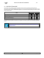
1
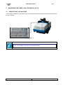
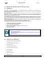
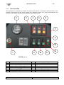
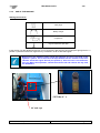
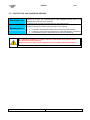
CS230 145B SWEEPER
OPERATOR MANUAL
Clemas & Co. Unit 5 Ashchurch Business Centre, Alexandra Way, Tewkesbury,
Gloucestershire, GL20 8NB.
Tel: 01684 850777
Fax: 01684 850707
Email: [email protected]
Web: www.clemas.co.uk
Congratulations for your choice!
FIORENTINI S.r.l. thanking you for the preference to our product, would like to remind you that
FIORENTINI S.r.l production covers manufacture and marketing of industrial cleaning machines
and is currently a leading company in this sector.
Our tradition and competence guarantee technical quality of your choice; actually all our products
are being built first quality materials through criteria that can give reliability, solidity and
functionality satisfying every kind of customers. FIORENTINI has recently obtained the quality
system certificate conforming to the requirements of UNI EN ISO 9001:2000.
We wish therefore inviting you to contact us, unhesitatingly, for every kind of request, as technical
or commercial; we’ll be pleased to be at your disposal for any information you may need.
INDEX
1.
GENERAL INFORMATION
2.
MACHINE FEATURES AND TECHNICAL DATA
2.1 IDENTIFYING THE MACHINE
2.2 DESCRIPTION AND FEATURES OF THE MAIN PARTS
2.2.1 DESCRIPTION
2.2.2 MAIN PARTS OF THE MACHINE
2.3 TECHNICAL DATA
2.3.1 DASHBOARD
2.3.2 USE OF THE MACHINE
3.
SAFETY
3.1 RIGHT USE OF THE MACHINE
3.2 WRONG USE OF THE MACHINE
3.3 SUGGESTED EQUIPMENTS
3.4 OPERATOR’S QUALIFY
3.5 PROTECTION AND WARNING DEVICES
3.6 OTHER DANGERS
3.7 SAFETY SIGNALS
1.1
1.2
1.3
1.4
SYMBOLS
PREMISES
MANUAL CONSULTING
WARRANTY
1.4.1
WARRANTY OBJECT
1.4.2 WARRANTY LIFE
1.4.3 WARRANTY APPLICATION
1.4.4 RETURNED GOODS
1.4.5 EXCEPTION
1.5 CONFORMITY DECLARATION
4.
STARTING THE MACHINE
4.1 TRANSPORT AND HANDLING
4.2 STORAGE
4.3 STARTING THE MACHINE
5.
MAINTENANCE
5.1 PERIODICAL MAINTENANCE
5.2 ENGINE MAINTENANCE
5.3 ELECTRIC SYSTEM CHECK UP
GENERAL INFORMATION
1
S34
GENERAL INFORMATION
1.1 SYMBOLS
This symbol is used to get the operator’s attention on procedures or precautions to be followed in
order to avoid damages to users or to the support.
This symbol is used to get the operator’s attention on general information.
1.2 PREMISE
FIORENTINI S. r. l. is the only owner of this manual.
The reproduction of all or part of the manual or the transmission to third parties with
mechanic or electronic devices are vorbidden without a written manufacturer’s authorization.
This manual is supplied to the customers in one original copy when differently specified
during the order.
This manual is supplied to the customer with the machine and it must be kept with it even when the machine has
to be transferred.
Please, keep the manual in a safe place and for all the machine lifetime. Purchaser is responsible for showing
the manual to qualified people. In case of loss ask for a duplicate to FIORENTINI Co..
FIORENTINI S.r.l. is not responsible for any kind of damages caused by people or things due to the nonobservance of the instructions of this manual.
FIORENTINI reserves the right to add at any time and without notice all the technical and commercial changes
considered useful for the customer. Therefore data and information in this manual can be updated.
Revisione 00 gennaio 2005
Pagina 4 di 47
GENERAL INFORMATION
S34
DICHIARAZIONE CE DI CONFORMITA’
ING. O. FIORENTINI s.r.l.
1.5.1.1.1.1.1 Loc. Rombola
50030 PIANCALDOLI (FI) ITALIA
SISTEMA QUALITA’ AZIENDALE
CERTIFICATO ISO9001
DICHIARIAMO SOTTO LA NOSTRA RESPONSABILITA’ CHE LA MACCHINA
Marca
FIORENTINI
Tipo
N° serie
Anno di costruzione
2006
RISULTA IN CONFORMITA’
con quanto previsto dalle seguenti direttive e normative armonizzate comunitarie:
DIRETTIVA COMUNITARIA
DIRETTIVA MACCHINE
98/37/CEE
DIRETTIVA COMPATIBILITA’ ELETTROMAGNETICA
89/336/CEE
Piancaldoli
Luogo e
data
Revisione 00 gennaio 2005
Ing. O. Fiorentini S.r.l.
Il titolare
Ing. O. Fiorentini
Firma
Pagina 7 di 47
TECHNICAL DATA
2
S34
MACHINES FEATURES AND TECHNICAL DATA
2.1 IDENTIFYING THE MACHINE
A silver label is sticked on the protection case of the steering column and clearly shows the data referring to
the “CE” marking.
PICTURE N° 1
The label has never to be removed. In case of damage it is necessary to ask for a
copy. The scrubber cannot be sold without the label.
Revision 00 January 2005
Page 8/47
TECHNICAL DATA
S34
2.2 DESCRIPTION AND FEATURES OF THE MAIN PARTS
2.2.1
DESCRIPTION
The sweeper – S34 - has been designed to clean flat and hard surfaces by means of a sweeping system and
suction of the dust into a suitable tank.
The traction system is based on oleodynamic engines fed by a pump which is driven by an endothermic
petrol or GPL engine.
The oleodynamic pump also feeds the engine of the central brush, the engine of the side brushes, the
oleodynamic actuators for the lifting and sink of the waste tank. The vacuum and the filter shaker engines
are fed by a battery supplied with the machine.
The sweeper is equipped with a side rotating brush (the left side brush is optional) which has to bring dust
into the central part of the machine. The main brush brings dust into the waste tank thanks to a suction
system. The machine must be used on dry or damp surfaces and can be equipped with a water system
which has to pull dust down.
Thanks to the dashboard the operator can control all the machine functions and a series of LEDs shows to
the operator the battery status or the errors detected by the electronic card.
The operator can control all the main functions of the machine and in particular:
¾
¾
¾
¾
¾
¾
start both the central and the side brushes;
start the dust pull down device (optional);
lift up or sink down of the waste dust;
open or close the flap set up in the front side of the machine;
start the vacuum engine;
start the filter shaker.
Important: before switching the machine off the operator must
¾
¾
2.2.2
sink the waste tank down;
lift the brushes up to avoid damages to the brushes bristles and decrease
their effectiveness.
MAIN PARTS OF THE MACHINE
¾ Zinc-plated steel or stainless steel frame;
¾
Lombardini diesel or GPL engine;
¾
RH rotating brush;
¾
LH rotating brush (optional);
¾
vacuum system to pick dust up;
¾
one drive wheel;
¾
two idle wheels;
¾
steering wheel assy;
¾
operator’s seat;
Revision 00 January 2005
Page 9/47
TECHNICAL DATA
¾
S34
dust pull down device (optional).
FIORENTINI Co., taking the new CE safety rules into consideration, manufactures the machine following the
CE directives about safety and health. The high quality material, the high technology and FIORENTINI
experience guarantee the performance and the reliability of this machine .
Each machine is tested during the manufacturing process and the final check is done before the machine is
shipped out.
Revision 00 January 2005
Page 10/47
S34
TECHNICAL DATA
2.3
TECHNICAL DATA
S34B
S34D
LENGTH
1980 mm.
1980 mm.
WIDTH
1119 mm.
1119 mm.
HEIGHT
1470 mm.
1470 mm.
1 central brush, 1 RH
brush (1 LH brush is
optional)
1 central brush, 1 RH
brush (1 LH brush is
optional)
hydraulic
Hydraulic
L. 850 mm. D. 300 mm.
L. 850 mm. D. 300 mm.
D. 550 mm.
D. 550 mm.
SWEEPING WIDTH WITH ONE SIDE BRUSH
1155 mm.
1155 mm.
SWEEPING WIDTH WITH TWO SIDE BRUSHES
1460 mm.
1460 mm.
PETROL TANK
*****
9 lt.
HYDRAULIC OIL TANK
22 lt.
22 lt.
FRONT WHEEL DIAMETER
375 mm.
375 mm.
REAR WHEEL DIAMETER
375 mm.
375 mm.
?
?
864 kg. with batteries
740 kg.
ENGINE
*****
LOMBARDINI LDW 702
CYLINDERS
*****
2
DISPLACEMENT
*****
700 cc
POWER
*****
17 HP
HYDRAULIC ENGINE OF THE CENTRAL BRUSH
OMM 32
OMM 32
HYDRAULIC ENGINE OF THE SIDE BRUSH
OMP 160
OMP 160
TRACTION HYDRAULIC ENGINE
OMS 200
OMS 200
COMER OVP 09
COMER OVP 09
GALTECH
GALTECH
MOVIMOTOR 36V
MOVIMOTOR 12V
MAN ON BOARD
MAN ON BOARD
U-TURN LANE
3450 mm.
3450 mm.
BRUSHES LIFTING UP SYSTEM
hydraulic
hydraulic
SERVICE BRAKE
mechanical
mechanical
PARKING BRAKE
mechanical
mechanical
FORWARD SPEED
6,6 km/h
7,6 km/h
REVERSE SPEED
6,6 km/h
7,6 km/h
FEATURES
SWEEPING BRUSHES
TRACTION
CENTRAL BRUSH DIMENSION
SIDE BRUSH DIMENSION
INTAKEN AIR VOLUME
WEIGHT WITHOUT OPERATOR
ENGINES
VARIABLE DELIVERY PUMP
FIXED DELIVERY PUMP
VACUUM ENGINES
FUNCTIONS
DRIVE
PERFORMANCES
Revision 00 January 2005
Page 11/47
S34
TECHNICAL DATA
MAX. SLOPE
?
?
MAX. SLOPE FOR AN U-TURN
?
?
9636 m²/h
9636 m²/h
Lp∆
72 dB(A)
LpiccoC 95 dB(c)
Lp∆
81 dB(A)
LpiccoC 103 dB(c)
A = 1,6 m/s2
A = 1,86 m/s2
CLEANING
ECOLOGICAL FEATURES
NOISE AT OPERATOR’S EAR
VIBRATIONS AT OPERATOR’S SEAT
The technical data listed above may be changed by the manufacturer without
notice. In any case, FIORENTINI is available for any further information or
explanation.
MEASUREMENT UNITS CONVERSION
Length
1 inch = 1” = 25,4 mm
Temperature T (K) = t (°C) + 273 / t (°F) = 1,8 t (°C) + 32
Revision 00 January 2005
Power
1 kW = 1,36 CV = 1,34 BHP
Pressure 1 bar =100 kPa = 14,5 psi
Page 12/47
S34
TECHNICAL DATA
2.3.1
THE DASHBOARD
The dashboard is composed by a series of switches that activate or disactivate all the functions of the
machine. The function of every switch is shown by a pictogram. Picture nr. 2 shows the dashboard. The
function of every switch and pilot light is explained in the scheme below.
2
3
4
6
8
7
5
13
1
9
10
11
12
PICTURE N° 2
1
2
3
4
5
6
7
Key switch
Hour counter
Petrol level pilot light
Engine temperature pilot light
Air filter switch (clogged filter)
Oil pressare pilot light
Glow plugs pilot light
Revision 00 January 2005
8
9
10
11
12
13
Battery charger pilot light
Horn button
Lights switch
Filter shaker switch
Suction engine switch
Vacuum engine pilot light
Page 13/47
TECHNICAL DATA
2.3.2
S34
USE OF THE MACHINE
Starting the machine.
Glow plugs
Battery charger
Oil pressure
Engine temperature pilot light
Insert the key into the dashboard and turn it once clockwise. Wait until the glow plugs pilot light (picture nr. 2
position 7) switches off and turn again the key clockwise in order to start the engine.
Before using the sweeper please check the hydraulic oil level in the tank of the
hydraulic system. The oil level must be kept between the two notches of the level
indicator inside the engine bonnet (see picture 3). If the oil level is not sufficient,
fill it up. Before this operation, switch the machine off and remove the key from
the dashboard.
PICTURE N° 3
Oil tank cap
Revision 00 January 2005
Page 14/47
S34
TECHNICAL DATA
Important: before starting the machine make sure that the accelerator lever is the
same position as shown in picture nr. 4. When the engine is running the lever
has to be moved towards the dashboard in order to increase the rpm.
Picture 4
Important: after having started the machine both the battery charger and the
motor oil pressure must switch off. Otherwise make reference to the engine user
manual.
Revision 00 January 2005
Page 15/47
S34
TECHNICAL DATA
Moving the machine.
Forward gear
Reverse gear
By means of the forward/reverse pedal the operator can move the machine. The operator has to put the foot
onto the pedal and press it with the heel to move forward or with the top of the foot to move the machine
backward.
Service brake
Forward/reverse
pedal
Picture 5
Revision 00 January 2005
Page 16/47
TECHNICAL DATA
S34
Before moving the machine make sure that the engine rpm is right. Otherwise, the operator can regulate the engine rpm
by means of the lever which is on the left side next to the hydraulic controls (see picture 6).
Rpm lever
Picture 6
Stopping the machine.
The sweeper is equipeed with one parking brake and one service brake. The last one (see picture 5) is controlled by a
pedal placed next to the forward/reverse pedal. The parking brake is controlled by a knob (see picture 7). The operator
has to pull this knob when the sweeper is not working. By means of the black little lever under the knob the operator can
release the brake.
Parking brake
knob
Picture 7
Revision 00 January 2005
Page 17/47
TECHNICAL DATA
S34
Important: the brake must be checked and registered every three months.
Driving seat regulation.
By means of the lever under the driving seat (see picture 8) the operator can regulate the horizontal position
of the seat itself.
Regulation lever
Picture 8
Revision 00 January 2005
Page 18/47
TECHNICAL DATA
S34
How to use the machine.
The operator can start the three functions of the machine by means of the three levers next to the driving seat. Make
reference to the scheme below for the explanation of the yellow sticker under the levers (see picture 9).
Picture 9
The operator has to pull the lever down in order to sink down and start the
rotation of the central and side brushes. Pulling the lever up the hydraulic
engines of the brushes stop and the brushes return in their original
position.
The operator has to pull the lever up in order to sink the waste tank down.
Pulling the lever down the tank returns in its original position.
The operator has to pull the lever up to open the flap and pick the dust up
into the waste tank. Pulling the lever down the flap closes.
Revision 00 January 2005
Page 19/47
TECHNICAL DATA
S34
The operator has to follow the rules below to sweep the surface:
¾
¾
¾
¾
start and sink the sweeping group down;
start the vacuum engine;
open the flap;
drive the sweeper at the same speed to clean all the surface.
The operator has to follow the rules below to empty the waste tank:
¾
close the flap;
¾
start the filter shaker to clean the vacuum filter;
¾
lift the waste tank up;
¾
open the flap, let the dust fall down from the waste tank and start the filter shaker again to clean the
vacuum filter ;
¾
keep away from the waste tank and make sure that nobody is near the sweeper. Sink the waste
tank down.
Revision 00 January 2005
Page 20/47
TECHNICAL DATA
S34
Main brush replacement
The operator has to follow the rules below to replace the main brush:
¾
by means of the lever (see picture n. 10) open the little door on the right side of the sweeper;
¾
unscrew the bolts (see detail 1 in picture 10) that hold the rubber catch sheet;
¾
remove the sheet;
¾
remove the dust cover rubber;
¾
unloose the knob and open the door that holds the brush (picture 11);
¾
remove the brush (picture 12);
¾
set a new brush up and check its holders;
¾
follow now the opposite operations.
Deatil 1
Dust cover rubber
Figura 10
Revision 00 January 2005
Page 21/47
S34
TECHNICAL DATA
Knob
Brush support
Picture 11
Picture 12
Brush holder detail
Revision 00 January 2005
Page 22/47
TECHNICAL DATA
S34
Side brush replacement
¾
¾
Unscrew the bolts (picture 13) and remove the brush;
replace the brush and tighten the bolts again.
Picture 13
How to replace the vacuum filter of the sweeping group and filter shaker engine
¾ Important: remove the key from the dashboard of the sweeper;
¾
open the bonnet of the machine by means of the button (picture 14);
¾ lift the waste tank cover up;
¾ unloose both screws that hold the filter (picture 15);
¾ remove the filter shaker support;
¾ disconnect the connectors of the shaker filter engine;
¾ lift up and replace the damaged or clogged filter;
¾ follow now the opposite operations.
Bonnet button
Picture 14
Revision 00 January 2005
Page 23/47
TECHNICAL DATA
S34
Connectors of the filter shaker
Fastening screws
Picture 15
Thanks to the vibrations of the filter shaker engine, the dust falls down from the filters into the waste
tank. If it is necessary, remove and replace the filter shaker engine.
Do not tighten the bolts of the shaker filter engine too much. Otherwise it may be
damaged.
How to clean the waste tank
The operator has to follow the instructions below to clean the waste tank:
¾ lift the waste tank up and open the flap;
¾ fasten the waste tank by means of the red safety lever (picture 16);
¾ clean the waste tank;
¾ place the red safety lever in its original position;
¾ sink the waste tank down.
Revision 00 January 2005
Page 24/47
TECHNICAL DATA
S34
Picture 16
Revision 00 January 2005
Page 25/47
SAFETY
3
S34
SAFETY
3.1 RIGHT USE OF THE MACHINE
This sweeper is equipped with an internal combustion engine and has been
designed to clean open spaces. S34 can pick up dust from horizontal surfaces or
with a slope not higher than 10% at a speed not higher than 3km/h. During a Uturn, the slope has not to be higher than 5%.
Revision 00 January 2005
Page 26/47
SAFETY
S34
3.2 WRONG USE OF THE MACHINE
The manufacturer is not responsible for damages due to a wrong use of the machine as stated in the
scheme below.
¾
¾
¾
¾
¾
¾
¾
¾
¾
¾
¾
¾
¾
The machine cannot be driven by non-authorized personnel;
The machine cannot sweep sloping surfaces whose gradient is higher than 10%
or surfaces with holes;
During a U-turn on a 5% sloping surface the machine has to be driven at a speed
not higher than 3 km/h;
The machine cannot be used in places with dangerous substances and in
particular with explosive atmospheres or with a bad microclimate;
The machine cannot clean surfaces with inflammable products;
The machine cannot be used as a means of transport for people or other means
of transport;
The machine protection devices cannot be modified or tampered;
Batteries must be recharged in a fanned room;
The operator have always to respect safety rules;
The operator cannot use equipments or devices that can create problems to the
machine working;
The machine components cannot be modified without FIORENTINI’s
authorization;
The operator cannot use acids that can damage the machine;
The operator has always to respect the rules written in the user manual.
¾
Please read carefully and do not cover the labels sticked on the machine.
FIORENTINI S.r.l. is not responsible for a wrong use of the machine (see § 3.2.)
Important. In case of fire use a dust extinguisher. Do not
use water.
Revision 00 January 2005
Page 27/47
S34
SAFETY
3.3 SUGGESTED EQUIPMENTS
In order to use the machine in a proper way, we suggest to use FIORENTINI equipments and original spare
parts.
FIORENTINI S.r.l. Technical Dept. is always at your disposal to design components or parts for a particular
use of machine as requested by the customer.
3.4 OPERATOR’S QUALIFY
OPERATION
OPERATOR’S QUALIFY
Driving/control of the machine
Trained operator
Installation/ disinstallation
Fiorentini technician
Mechanical parts maintenance
Mechanic/trained technician
Electrical parts maintenance
Electrician/ trained technician
Hydraulic system maintenance
Mechanic/ trained technician
Cleaning of the machine
Unskilled worker
Dismantling and demolition
Unskilled worker
FIORENTINI S.r.l. suggest to train the operator before using the
machine. The operator must be trained about safety rules and
carefully read this manual.
FIORENTINI S.r.l. is not responsible for any possible damage to people and/or things
caused by the non-observance of the instructions dealt within this manual.
Revision 00 January 2005
Page 28/47
SAFETY
S34
3.5 PROTECTION AND WARNING DEVICES
Side brush case
Warning device
The machine is equipped with a nylon central brush that rotates while the
machine is on duty. The machine cannot reach dangerous areas thanks to a
stainless steel case set up on the brush.
The operator can remove the brush case only with special tools.
S34 sweeper is equipped with three warning devices that have to prevent
dangers if somebody is near the machine durino the cleaning.
¾
¾
¾
an acoustic warning device durino the normal use of the machine;
a warning acoustic and intermittent device while the operator is reversing;
a yellow flashing light to signall that the machine is functioning.
It is absolutely forbidden to camper, remove or disactivate these devices durino
the normal use of the machine.
Please check their effectiveness regularly (read the chapter about maintenance).
Revision 00 January 2005
Page 29/47
SAFETY
S34
3.6 OTHER DANGERS
Starting from the design of the machine, FIORENTINI studies every kind of danger that can occur whilst
using the sweeper in order to prevent or at least reduce the number of accidents for the operator.
The operator can avoid many risks that can occur during the machine operating thanks to a series of signals
on the machine.
SQUASHING
This kind of danger can occur:
•
whilst regulating the central brush;
Whilst regulating the central brush, the ignition key must be kept away from the dashboard in order
to avoid the casual starting of the machine.
TURNOVER
This kind of ranger can occur:
•
during the normal use of the machine when sloping limits are not respected - as specified in
the manual – or whilst cleaning disconnected surfaces or surfaces with holes and high
depressions (photo 3.2)
Do not use the machine to wash sloping surfaces higher than 12% or surfaces with holes
or depressions which might compromise the stability of the machine.
FIORENTINI is not responsible for accidents occurred to people or things
provoked by a wrong use of the machine, i.e. using the machine on surfaces
which can compromise its stability.
The purchaser must stick proper labels on the machine to show the operator the
right use of the sweeper.
Revision 00 January 2005
Page 30/47
SAFETY
S34
3.7 SAFETY SIGNALS
On the brushes protection cases of the machine the operator can find stickers that show different dangers that
can occur whilst operating with the sweeper.
Dangers’ signals are triangular with black pictures on
a yellow background
DANGERS
Prohibitions’ signals are round with black pictures
and a red stripe
PROHIBITIONS
What is it?
This signal forbids to remove the protection of pieces in movement.
What to do
During the installation or the maintenance make sure that the
ignition key is not in the dashboard before removing the mobile
protections.
While the machine is operating make sure that all covers are well
fixed.
Picture 17
Revision 00 January 2005
Page 31/47
SAFETY
S34
What is it?
Squashing ranger: this can of ranger can occur when the engine cover is
open.
What to do
Whilst installing or maintaining the engine, the operator has to stop the
engine cover with its rod.
Picture 18
The purchaser must replace danger signals on the machine if they are
deteriorated. It is absolutely forbidden to remove or temper danger signals.
Revision 00 January 2005
Page 32/47
SAFETY
S34
What is it?
This signal shows fire ranger due to inflammable liquids.
What to do
Whilst filling the tank with petrol, the operator has to use a suitable funnel
to avoid to dirt the machine. Moreover, this operation has to be done in a
proper place where no primer danger can occur.
Picture 19
Revision 00 January 2005
Page 33/47
HOW TO START AND USE THE MACHINE
4
S34
HOW TO START AND USE THE MACHINE
4.1 TRANSPORT AND HANDLING
The machine is delivered to the purchaser in a proper package (see picture 4.1 below). A black arrow on the
package shows the barycentre. This arrow must be in the middle of the elevator or transpallet forks. The
package must be carefully handled. Do not place one package on another one. If agreed with the purchaser,
the machine can be delivered without package, placed on a pallet and fixed by means of straps.
The purchaser must make sure that the machine has not been damaged during the
transport and that all papers are on the machine. Otherwise, the purchaser must
immediately contact FIORENTINI in order to sort out the problem.
The purchaser is responsible for the transport of the machine if not differently
agreed with FIORENTINI.
Picture 20
Revision 00 January 2005
Page 34/47
HOW TO START AND USE THE MACHINE
S34
The machine must be handled with proper devices as stated in the scheme below. Please, make sure that
the black arrow on the package is always in the middle of the elevator forks or the sling bands.
Anchorage and/or sling points are set on the machine up in order to keep the stability of the sweeper during
the handling.
PACKAGE
HANDLING EQUIPMENT
PICTURE
Paperboard or plywood box
on a pallet
Fork elevator
No. 17
None
Fork elevator or crane truck with a two-band-sling and
equalizer
No. 18
LOADING SYSTEM
Picture 21
Picture 22
Make reference to § 2.3. for the dimensions and the weight of the machine.
Trained personnel only can handle the machine.
The bands used to lift the machine up must have the same loading capacity as the
machine load. Handling operations must be done without causing a loss of
stability of the machine. Otherwise, the machine can be damaged or the operator
can de in danger.
Revision 00 January 2005
Page 35/47
HOW TO START AND USE THE MACHINE
4.2
S34
STORAGE
The machine must be stored in a closed and dry place if not immediately installed in order to keep every part
safe.
Relative humidity must be lower than 80% and the storage temperature must be between 3°C ≤ t ≤ + 45 °C.
Revision 00 January 2005
Page 36/47
S34
HOW TO START AND USE THE MACHINE
4.3 STARTING THE MACHINE
S34 sweeper can be starter only after a complete check up of all its components and safety devices.
This is why, well trained FIORENTINI technicians do a strict control while manufacturing the machine and an
accurate final test. Anyway, FIORENTINI suggests to do another test before starting the machine. Please
see the scheme below.
Test
Result
√
X
Hydraulic oil level
Engine oil level
Engine cooling water level
Wheels brake functioning
Pilot lights functioning
If the result of the test is positive, the machine can be started. On the contrary, please contact immediately FIORENTINI
service.
The test above must be periodically carried out in order to keep the machine
always efficient.
Revision 00 January 2005
Page 37/47
MAINTENANCE
5
S34
MAINTENANCE
5.1 PERIODICAL MAINTENANCE
A periodical maintenance is important in order to keep the machine efficient. Please fill in the format below
all the interventions done on the machine.
If the original product is not conform, do not use it and wait for the repair or
replacement of the defected part.
Maintenance must be carried out by trained personnel only especially for the
electrical or electromechanical systems. Technicians must use suitable tools
for every kind of intervention. Make reference to FIORENTINI SERVICE only for
original spare parts (§ 7.1. / 7.2.).
Revision 00 January 2005
Page 38/47
S34
MAINTENANCE
OPERATION
INTERVENTION
HOW OFTENA
Clean the waste tank and the oil filter of the suction motor
•
Cleaning
Do not use corrosive
substances.
•
Do not use bolts of
water.
¾
Controlli
Check the oil level of the hydraulic system
Daily
Every week
Check and regulate the braking system
Every 3 months
Check if the battery cables are well fixed
Every 6 months
¾
¾
Check the safety devices
Check the electric system
Every year
¾
Complete overhaul
Revision 00 January 2005
Every 5 years
Page 39/47
MAINTENANCE
S34
5.2 ENGINE MAINTENANCE
In order to maintain the internal combustion engine, the operator has to check:
¾
¾
¾
¾
¾
¾
¾
¾
¾
the engine oil level every 50 hours and replace it every 150 hours;
the coolant every 50 hours;
replace the air filter every 100 hours;
replace the petrol filter every 250 hours;
replace the engine oil filter every 300 hours;
replace the hydraulic oil filter every 750 hours;
check the tension of the alternator belt every 250 hours;
clean and set the injector every 1000 hours;
adjust the equalizers slack every 1000 hours.
For any kind of intervention on the engine please follow the instructions of the
engine logbook delivered with the machine.
Revision 00 January 2005
Page 40/47
MAINTENANCE
S34
5.3 CHECKING THE ELECTRIC SYSTEM
It is very important to check the electric system up every two years. Disconnected cables or burnt cables
must be immediately replaced.
Interventions on the electric system must be carried out by a trained technician.
Every kind of intervention not explained in the operator manual must be carried
out by FIORENTINIs technicians.
Revision 00 January 2005
Page 41/47