1
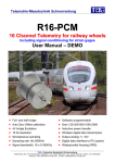
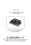
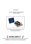
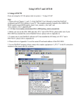
EG2000 Generator Electronic Governor Controller Operation Manual Smoke Limit Control, IDLE Speed Control, suitable for Built-in, Non-Built-in and PT Pump Type Actuator Headquarters : No.3, Lane 201, Chien Fu St., Chyan Jenn Dist., Kaohsiung, TAIWAN Tel : + 886-7-8121771 Fax : + 886-7-8121775 URL : http://www.kutai.com.tw SECTION 1 : SPECIFICATION Operating Voltage Voltage 12 / 24 Vdc +/- 20% Droop 4% Output Current Current 0.5 15 A Adjustment Run Speed, IDLE Speed, Ramp Time, Droop, Gain, Integration (INT.) Run Speed Adjustment Range Speed adjustment Potentiometer (30 turn) 4 Segment DIP Switch Adjustment From 600 9500 Hz IDLE Speed Adjustment Range Run Speed 30 85% Ramp Time 3 20 Sec Remote Speed Pot Ext. Remote speed pot terminal 6, 7, 8 (ILS) and 6, 7, 9 connect a 5K ohms potentiometer +/- 5% adjustment range. Run Speed Stability Less than +/- 0.25% Temp. Stability Less than 0.01% Environment Operation Temperature Storage Temperature Relative Humidity Vibration -40 to +85 ˚C -40 to +85 ˚C Max. 95% 1.0 G @ 18 – 30 Hz 2.5 Gs @ 48 – 70 Hz Dimensions 147.0 (L) x 114.0 (W) x 50.0 (H) mm Weight 690 g +/- 2% MPU Input Signal 1 120 Vac RMS SECTION 2 : Function Descriptions 2.2 The EG2000 provides both an adjustable IDLE Speed and ramp, for controlling engine smoke, vibration and warm-up. 2.2.1 Protect the EG2000 by installing it inside the engine instrument control panel. 2.1 2.2.2 Mount the Actuator close to the engine fuel system. See actuator manufacture instructions. Controller Together, the EG2000 Controller, Actuator and MPU (Magnetic Pickup) form the electronic engine governor assembly. The EG2000 receives the signal from the MPU and, depending on the engine RPM, the actuator controls the fuel intake on the engine. The EG2000 receives its power from the engine batteries or an AC to DC power supply rated from 12 or 24 Vdc +/- 20% matching the Actuator voltage. The average operating current is around 2.5 to 3.5 amps, but it may reach 15 Amps during engine start or sudden load changes. Installation Descriptions 2.2.3 Always choose a point on the actuator control arm in which it can rotate freely, providing minimum and maximum fuel (But do not bottom out the actuator; leave 2 to 3 degrees before the off and on position). 2.2.4 Use a Non-Linear link on Gas engines to get low Gain at light loads and high Gain at heavy loads and a linear link on diesel ejection pumps. 2.2.5 Mount the magnetic pickup on the flywheel bell housing to count the teeth on the ring gear. The teeth are converted to an electrical pulse by the MPU. These pulses are cross referenced with the original setting on the EG2000. Any difference is used by the actuator to change engine RPM to maintain the same pulse count. ___________________________________________________________________________________________ 2 EG2000 SECTION 3 : CONNECTION Terminal 1, 2 DC Power Input 2, 3 IDLE Terminal 4, 5 6, 7, 8 6, 7, 9 For ACT, Max @ 15A 10、11 MPU input, Ground Terminal No. 10 Remote speed control. Connect 5K ohms potentiometer approx. +/- 5% adjustment range. 3.1 Terminal 1 & 2 used for DC power input. Terminal 1 for Positive (+) and Terminal 2 for Negative (–) input -Voltage can be 12/24 Vdc +/- 20%. 3.2 Terminal 2 & 3 are the IDLE SW. Terminal when 2 & 3 open normal Run Speed, When Terminal 2 & 3 shorted engine in IDLE. 3.3 Terminal 4 & 5 is the output terminal for the actuator, providing a maximum of 15A. 3.4 Terminal 6 and 7-8 and terminal 6 and 7-9 are two sets of remote speed control. Referring to figure 4, connect a 5K ohms potentiometer, and turn the knob to central position. Let engine run on Run Speed to adjust to the rated engine speed, the adjustable range is +/- 5%. Users can also series a resistor to the potentiometer variable point to either terminal 8 or 9 to narrow the adjustable range. The wirings used to connect to terminal 6, 7-8 and 6, 7-9 must use the 3-wire shielded cable. The drain shield wire is to be connected to terminal 10 and the other end of the drain shield wire must cut off and taped. 3.5 Terminal 10 and 11 is the MPU signal input terminal. The wiring used to connect to the terminals must use a 2-wire shield cable. The drain shield wire is to be connected to Terminal 10 and the other end of the drain shield wire must cut off and taped. 3.6 (2) Adjust Run Speed to minimum and let Terminal 2 & 3 be Open Circuit. (3) Start engine. The engine speed may rev to Run Speed right away. Slowly adjust Run Speed to the rated generator RPM. (4) Short Terminal 2 & 3 the engine speed should drop, slowly set IDLE Speed to a comfortable engine IDLE. (5) Stop engine and adjust Ramp. Time to it center setting then restart engine. At this time, the engine speed will stay in IDLE and slowly Ramp up to normal engine speed. Adjust to preferred Ramp speed. Refer to Figure 1. (6) When operating at normal RPM closing the IDLE SW, decreases engine RPM back to IDLE RPM according to preset Ramp Time. (7) To ensure positive engine starts every time follow step (4) and turn the IDLE Speed potentiometer an additional 3 to 5%. 4.1.2 Ramp Time. (1) On hot engines, a specific fuel limit setting will control start-up smoke, but not completely. A hot engine does not need the same fuel limits to start as a cold starting engine. (2) Ramp Time can be set from 3 up to 20 seconds. The Ramp Time is the length of time from IDLE to the rated Run Speed. Figure 1 Harness used to connect to Terminal 1, 2, 4 and 5 must use the 2.0mm twist pair harness. SECTION 4 : OPERATION 4.1 IDLE Speed and Smoke Limiting Adjustment The EG2000 has two settings used for smoke limiting : 4.1.1 IDLE Speed:The setting of the lowest engine operating speed. (1) Before firing the engine, adjust the IDLE Speed to the maximum, and Ramp Time to the minimum. ___________________________________________________________________________________________ EG2000 3 4.2 Isochronous Adjustment Isochronous operation is obtained by setting Droop potentiometer fully counterclockwise. EG2000 is normally operated in the isochronous mode; i.e., engine RPM is constant (+/- 0.25%), under steady state load conditions, up to the engine’s maximum capability, regardless of load on the engine. Please refer to Figure 2. 4.4 Remote Speed POT Adjustment EG2000 is equipped with 2 sets of Remote Speed Potentiometer adjustment. By adding a 5KΩ Potentiometer, user can adjust the engine speed from as far as 60 meters away from the engine. Please refer to Figure 4 for connection. To narrow the adjustment range, series a resistor on either Terminal 8 or 9 to reduce. Without the resistor the adjustment range is approximately 5%. 4.5 Integration (INT.), GAIN Adjustment (1) Shutdown engine and DC input turned off. (2) Potentiometer original setting. (3) Adjust INT., Gain and Ramp Time Potentiometer to minimum setting (Fully Counterclockwise) (4) Under Isochronous operation, set Droop potentiometer fully counterclockwise. (5) Set the MPU frequency range : Figure 2 4.3 Select the suitable frequency setting according to the highest engine frequency range. Non-Isochronous Operation Input Signal Frequency : When operated under Non- isochronous (Paralleled), Droop is used to distribute the actual power from the generators. Please refer to Figure 3. RPM × Flywheel teeth 60 sec Droop operation is obtained by setting the Droop potentiometer. Moving Droop Pot clockwise increases the Droop. The amount of Droop for a given setting depends on the magnetic pickup frequency and no load to full load actuator shaft rotation. Frequency Selection SW-1 ON 600 1200 Hz SW-2 ON 1200 2500 Hz SW-3 ON 2500 5000 Hz SW-4 ON 5000 9500 Hz (If uncertain Set SW3-ON and the balance to OFF) (6) Idle Speed set to maximum, Run Speed set to minimum (7) Adjust Remote Speed POT to central (If used) (8) Start Engine Figure 3 A Droop potentiometer setting of 10 o’clock will give about 4% Droop, no load to full load when the pickup frequency is 4260 Hz and actuator shaft rotation is approximately 30 degrees from no load to full load. Lower pickup frequency or smaller shaft rotation results in less Droop for the system. At this time the engine should rev to Run Speed, (If engine speed exceeds its rated speed, Stop engine and immediately choose a lower frequency setting) slowly adjust Run Speed pot clockwise to the rated engine speed. For Idle Speed, Ramp Time And Idle Sw Setting, Reference To Paragraph 4.1 (9) Slowly adjust Gain clockwise until the actuator begins to oscillate. (10) Slowly adjust Gain counterclockwise until it becomes stable. ___________________________________________________________________________________________ 4 EG2000 ● Please reference from 4.2 and 4.3 for Droop setting. (11) Manually move the linkage. If the linkage oscillates 3 to 5 times and then stabilizes, then the setting is correct. (12) If engine speed overly increases or decreases when adding load or reducing load, please adjust the Gain VR clockwise a little. (13) If engine speed recovers too slowly, adjust INT. (Integration) clockwise, in the same time decrease the GAIN setting. Observe the actuator linkage. If the linkage is stable, manually adjust the linkage. If the linkage slowly oscillates, then the response time is inadequate. Adjust INT. clockwise until the response is improved. (14) Again manually adjust the linkage. If the linkage begins to oscillate 3 to 5 times and then stabilizes, then the setting is complete. Note 1:If GAIN or INT. (Integration) is over adjusted, it causes the engine speed to oscillate. Repetitively increasing and decreasing the GAIN and INT. arrangement can help to obtain the best performance. Note 2:Due to different types of external and internal built-in type actuators, the adjustment of Gain is very important, together with INT. (Integration) adjustment. In PT pump type actuators, the movement is very limited, so Gain is set to the minimum using INT. (Integration) to adjust engine speed compensation. SECTION 5 : DIMENSION AND TYPICAL WIRING DIAGRAM DROOP INT. GAIN RAMP-TIME SW POWER : DC12/24V SW1-ON 600~1200HZ SW2-ON 1200~2500HZ SW3-ON 2500~5000HZ SW4-ON 5000~9500HZ IDLE SPEED REMOTE SPEED POT + 1 IDLE 2 3 4 5 RUN SPEED ~ ILS ACT 6 7 8 9 Idle switch 10 MPU 11 Cable A Cable B R + Magnetic Pickup _ DC Power Actuator CCW 5K CW Wiring Drawing Figure 4 * Cable A, B - use a cable with a wrapped Mylar aluminum foil shield with a drain wire. 1. To connect the DC power supply and actuator use a 12 AWG / 2mm twist pair harness. * To connect the 5K ohms potentiometer, refer to paragraph 3. Connections. 2. Connect the MPU to the EG2000 using a 2-wire shielded cable. Anchor the drain shield wire to Terminal 10 and the other end cut and tape off. ___________________________________________________________________________________________ EG2000 5 SECTION 6 : TROUBLESHOOTING PROBLEM Actuator goes to full stroke when DC power is turned on (Engine is not operating) Governor is completely dead and actuator lever stays at minimum position when power is applied to governor. CORRECTIVE ACTION 1. Check magnetic pickup leads for proper shielded wire or open shield. Verify and correct wiring as necessary. Be sure there is no jumper between terminals 2 and 3. 2. Failsafe circuit in the controller may be damaged or defective. Replace with new controller. 3. With DC power OFF remove leads at actuator. Check continuity of conduction on each terminal to case. There should be no continuity of conduction between any terminal and case of EG2000. If conduction is measured, please replace the controller. 4. If remote speed potentiometer has been connected to terminals 6, 7 and 9 of the controller, disconnect these leads. Turn DC power ON to the governor if the actuator is now normal. Proceed to corrective actions for the next problem. 1. Check battery voltage at terminals 1 and 2 on controller. Terminal 1 is positive. Check battery connections and contacts for turning power ON to the controller. 2. Check for proper linkage setup. Correct and free linkage. 3. Magnetic pickup signal absent or too low. Measure AC voltage across terminals 10 and 11 while cranking the engine. Voltage should be min. 1.0 Vac. NOTE : The voltmeter should have an impedance of 5000 ohms / volts or higher. Check pole tip gap over gear tooth. Should be 0.037 mm / - 0.127 mm. Erratic governor operation 4. Measure the resistance of the magnetic pickup coil. This should be above 50 ohm. If there is an open or shorted coil, replace the magnetic pickup. 5. Measure the resistance of each pin to the metal case of the magnetic pickup. No continuity should be evident. 6. If there is continuity of conduction to the case, replace with new magnetic pickup. 7. Measure actuator coil resistance : If actuator coil is open or shorted to case, replace the actuator. If governor still does not operate, continue with steps below. 8. Measuring the resistance of each coil lead to the actuator case should indicate an open circuit on a low scale of the ohm meter. If continuity is defected, replace the actuator. 9. With DC to the governor ON and the engine OFF, measure the DC voltage from terminal 6(+) to terminal 2(-). This should be approx. 4 Vdc. If 4 Vdc is not present, replace the controller. 10. Between terminal 7(+) and terminal 2(-), the voltage should be approx. 4.6 Vdc. If 4.6 Vdc is not present, replace the controller. 1. Measure DC voltage at 1 and 2 on controller terminal strip. Normal battery voltage should be indicated. If nominal voltage is present, wiring is correct. 2. Low battery voltage 20% below rated can cause erratic operation. Check battery and charging system. 3. RFI noise due to incorrect shielding. Correct wiring. 4. RFI noise fed through power supply leads. Connect power leads directly to the battery. ___________________________________________________________________________________________ 6 EG2000 PROBLEM Improper operation from remote speed potentiometer CORRECTIVE ACTION 1. Investigate wiring to remote speed potentiometer for open or shorted circuits. Checking wiring. 2. If the leads at terminals 6 and 7 to the remote speed potentiometer are reversed, speed control by the remote speed potentiometer will be reversed. Correct wiring. 3. Lead wire to remote speed setting potentiometer should be 3-wire shielded cable. Verity that the drain shield wire is isolated from ground at the potentiometer. If terminal 6 lead to the remote speed potentiometer is open, engine speed will go high. Correct the wiring. 4. If lead 8 and 9 (wiper lead to remote potentiometer) is open, there will be no control by the remote speed potentiometer. Verify and correct wiring. 5. If lead 7 to the clockwise terminal of the remote speed potentiometer is open, speed will remain at the value set in EG2000. Slow, small amplitude hunting of speed or frequency Fast oscillation of governor linkage Engine will not start – Actuator goes to full fuel during cranking Jammed or very loose linkage. Correct linkage. Verity calibration setting of the controller. Readjust setting as necessary. 1. Make sure fuel is available. Check fuel to engine. Check for correct wiring to the automatic shutdown circuits. 2. Air may be trapped in fuel line. Check fuel lines for leaks. 3. Try to operate engine manually. ※ Appearance and specifications of products are subject to change for improvement without prior notice. ___________________________________________________________________________________________ EG2000 7