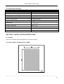
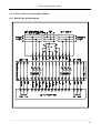
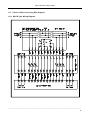
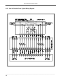
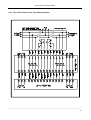
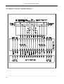
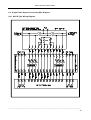
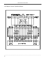
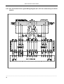
1
ATS-01
Ver1.2
AUTOMATIC TRANSFER SWITCH
CONTROL UNIT
OPERATOR’S MANUAL
Headquarters : No.3, Lane 201, Chien Fu ST., Chyan Jenn Dist., Kaohsiung, TAIWAN
Tel : + 886-7-8121771
Fax : + 886-7-8121775
URL : http://www.kutai.com.tw
ATS-01 Automatic Transfer Switch
TABLE OF CONTENTS
Section
Page
SECTOIN 1 : INTRODUCTION
1.1 Preliminary Comments and Safety Precautions .............................................................................. 3
1.2 Overview .......................................................................................................................................... 3
1.3 Product Overview............................................................................................................................. 3
1.4 Functions / Features ........................................................................................................................ 4
SECTOIN 2 : HARDWARE DESCRIPTION
2.1 General............................................................................................................................................. 6
2.2 Display Window................................................................................................................................ 6
2.3 Operate Pushbuttons ..................................................................................................................... 6
2.4 Panel LEDs Outputs ....................................................................................................................... 6
2.5 Rear Access Area .......................................................................................................................... 6
SECTOIN 3 : OPERATOR PANEL
3.1 General............................................................................................................................................. 9
3.2 Display Window................................................................................................................................ 9
3.3 Operate Pushbuttons ....................................................................................................................... 9
3.4 Panel LED Outputs .......................................................................................................................... 9
SECTOIN 4 : OPERATION
4.1 General........................................................................................................................................... 10
4.2 Automatic Mode ............................................................................................................................. 10
4.3 Engine Test Mode .......................................................................................................................... 11
4.4 Off Mode ........................................................................................................................................ 11
4.5 Programming Mode........................................................................................................................ 11
4.6 Specification Summary .................................................................................................................. 13
SECTOIN 5 : INSTALLATION INSTRUCTIONS
5.1 General........................................................................................................................................... 13
5.2 Panel Cut-Out ............................................................................................................................... 13
5.3 Unit Dimensions ........................................................................................................................... 14
SECTOIN 6 : TYPICAL WIRING
6.1 General........................................................................................................................................... 14
6.2 3 Phase 3 Wire Connecting Wire Diagram .................................................................................... 15
6.3 1 Phase 3 Wire Connecting Wire Diagram .................................................................................... 19
6.4 Single Phase Connecting Wire Diagram........................................................................................ 23
6.5 Connecting Wire Diagram When The Transfer Current Over 6 Amps .......................................... 27
______________________________________________________________________________________
2
ATS-01 Automatic Transfer Switch
SECTION 1 : INTRODUCTION
1.1 Preliminary
Comments
and
Safety
Precautions
This technical document is intended to cover most
aspects associated with the installation, application,
operation and maintenance of the ATS-01
Automatic Transfer Switch Controller. It is provided
as a guide for authorized and qualified personnel
application of the ATS-01 Automatic Transfer Switch
Controller.
3. Intelligence control unit to constantly monitor the
condition of the power sources and thus provide
the intelligence necessary for the switch and
related circuit operation.
This manual deals with the third basic element of
the automatic transfer switch, the required
intelligence automatic control module. All the
Automatic Transfer Switch functions were
performed by a door mounted logic panel ATS-01
control unit. The ATS-01 logic panel brings
intelligence,
supervisory
and
programmable
capabilities to automatic transfer switch equipment.
1.2 Overview
1.3 Product Overview
Transfer switches are used to protect critical
electrical loads against loss of power. The load's
normal power source is backed up by a standby
(emergency) power source. A transfer switch is
connected to both the normal and emergency
sources and supplies the load with power from one
of these two sources. In the event that power is lost
from the normal source, the transfer switch transfers
the load to the standby source. Once normal power
is restored, the load was transferred back to the
normal power source.
The ATS-01 Automatic Transfer Switch control
module is an intelligence, comprehensive,
multi-function, microprocessor based automatic
transfer switch controller. It is a compact panel
mounted device designed to replace traditional relay
and solid state logic panels and meet the needs of
markets worldwide.
The ATS-01 controller provides an unmatched
degree of programmed flexibility to address the
needs of most switches system. It can be
programmed for 3Ø, 1Ø and 1Ø 3W system
operation. ( Refer to program line 2 )
When using the ATS-01 module in automatic
transfer switch equipment, the switch's intelligence
system initiates the transfer when normal power
falls below or over a preset voltage or frequency. If
the emergency source is a standby generator, the
transfer switch initiates generator starting and
transfers to the standby source when sufficient
generator voltage and frequency is available. When
normal power is restored, the transfer switch
automatically transfers back and initiates engine
shutdown after a preset engine cooling down time
delay.
● Monitor Normal and Standby source over and
under frequencies.
An automatic transfer switch consists of three basic
elements:
● Permit customer programming display real time
information.
1. Main contacts to connect and disconnect the load
to the source of power.
● Permit customer programming cyclic mode or fix
mode display for 3 phase voltages and frequency.
( Refer to program line 29 )
2. A transfer mechanism to affect the transfer of the
main contacts from one source to another source.
● Permit system testing the transfer switch
with/without load from front panel. ( Refer to
program line 4 )
The ATS-01 controller provides the necessary
intelligence to insure that the switch operates
properly through a series of programmed sensing
and timing functions. The ATS-01 controller will :
● Monitor Normal and Standby source over and
under voltages.
● Store customer / factory established parameters
in memory without losing.
______________________________________________________________________________________
3
ATS-01 Automatic Transfer Switch
● Built-in one week exerciser timer.
Feature 1 :Time Delay Normal to Emergency
● Permit customer plant engine test with / without
load on a preset period.
(TDNE)
● Provide programmable per-exerciser warming
signal.
● Provide a pre-transfer signal to elevator controller
before transfer switch.
● Provide programmable
transfer failure.
alarm
output
when
● There is no need for a PC connection and
programming software. Any and all changes can
be made in the field.
● Provide the source status and fail alarm
indications on the front panel.
1.4 Functions / Features
The primary function of ATS-01 controller is to
accurately monitor power sources and provide the
necessary intelligence to operate a transfer switch
in an appropriate and timely manner.
1.4.1 Operational Simplicity
From installation to programming to usage, the
ATS-01 controller was designed with operational
simplicity in mind. The ATS-01 controller operates
with system voltage from 160 VAC to 260 VAC at 50
or 60 Hz. The user-friendly front panel interface
simplifies routine operation, programming and
setting adjustments.
TDNE provides a time delay when transferring the
Normal source to the Standby source. It ensures
stability of the Standby source. Timing begins when
the Standby Source becomes available. ( Refer to
program line 6 )
Adjustable TDNE range : 0 ~ 60 (0 ~ 300 sec)
Feature 2 : Time Delay Engine Start (TDES)
TDES delays the initiation of the engine start circuit
in order to override momentary power outages or
voltage fluctuations of the Normal source. The
TDES timer shall start when the Normal source
becomes unavailable. If the Normal source
becomes available while timing, the TDES timer will
reset. The ATS-01 controller can perform the time
delay engine start function without control power for
30 seconds. ( Refer to program line 7 )
Adjustable TDES range : 0 ~ 6 (0 ~ 30 sec)
Feature 3 : Time Delay Emergency to
Normal (TDEN)
TDEN delays the transfer from the Standby source
to the Normal Source to permit stabilization of the
Normal Source before retransfer is made. Timing
begins when the Normal Source becomes available.
( Refer to program line 5 )
Adjustable TDEN range : 0 ~ 60 (0 ~ 300 sec)
1.4.2 Standard Features
A variety of programmable features are available to
meet a wide variety of application requirements.
Individual features or feature combinations provide
the intelligence required tailoring switches to
individual needs. The features can be programmed
by customer via friendly setting procedure,
depending upon customer requirements. The
specific variable set points associated with standard
and factory activated features are stored in a
nonvolatile memory. Activated feature set points are
available for customer adjustment.
Feature 4 : Time Delay Engine Cool-down
(TDEC)
TDEC permits the generator to continue to run
unloaded after retransfer to the Normal Source has
occurred. Timing begins when the transfer to normal
has been completed. ( Refer to program line 8 )
Adjustable TDEC range : 0 ~ 60 (0 ~ 300 sec)
______________________________________________________________________________________
4
ATS-01 Automatic Transfer Switch
Feature 5 : All Phase Under / Over voltage
Feature 10 : Transfer Fail Alarm Signal
Sensing
Output
The controller monitors the voltage of each phase of
the normal and standby power source. User
adjustable settings are provided. ( Refer to program
line 9,10,11,15,16 & 17 )
When the auxiliary contactor was set
transfer fail alarm output. The auxiliary
may be wired to an alarm enunciator
indicate problem with the Automatic
Switch.
to be a
contactor
panel to
Transfer
Adjustable Over voltage range : 110VAC ~ 550VAC
Adjustable Under voltage range : 80VAC ~ 470VAC
Feature 6 : Under/Over frequency Sensing
The controller monitors the frequency of the normal
and standby power source. User adjustable settings
are provided. ( Refer to program line 12,13,14,18,19
& 20 )
An alarm condition will occur if a transfer has been
initiated but it is never completed. This may indicate
that something is wrong with the motor or transfer
mechanism. ( Refer to program line 30 )
NOTICE
The ATS-01 controller provided an aux.
contactor for external signal output only. So,
Adjustable Over frequency range : 51Hz ~ 70Hz
this contactor just can define to one of the
Adjustable Under frequency range : 45Hz ~ 47Hz
three features used. (Pre-transfer, Pre-exerciser
or Transfer fail alarm output.)
Feature 7 : Plant Exerciser
This feature provides for automatic test operation of
the generator. The interval is fixed at once per week
with a specific test day and time. The test period is
also programmable by customer setting. The
ATS-01 control unit permit customer plant engine
test with / without load on a preset period. ( Refer to
program line 21,22,23,25,26,27 & 28 )
Feature 11 : Fail Alarm On Display
Feature 8 : Pre-transfer Signal Output
FAIL on the front panel of the ATS-01 indicates that
a transfer was initiated but never completed. This
can point toward a defective motor, transfer
mechanism or the wrong programming for line
3.When the transfers fail alarm occurred, the ATS
will hold this position until the OFF button is pressed
to reset alarm signal.
When the auxiliary contactor was set to be a
pre-transfer signal output. The ATS-01 controller will
provide a pre-transfer signal to elevator controller
before transfer the load from one source to another
source with a preset time delay. The pre-transfer
return to normal state after the transfer is complete.
( Refer to program line 30 & 31 )
NOTE! Normally, MCCB type ATS need longer
running time to complete there cycle, so if line 3 is
set wrong the switch stops before completing it’s
cycle and the ATS-01 will give you a FAIL transfer
Alarm. Make sure the line 3 setting is set right
before checking any other parts of the ATS
mechanism.
Adjustable range : 1 ~ 99 sec.
Feature 9 : Pre-exerciser Signal Output
When the auxiliary contactor was set to be a
pre-exerciser signal output. The ATS-01 controller
will provide a pre-transfer signal output before
exerciser the engine. It is an advance warring to
avoid person damaged before the generator auto
start itself. ( Refer to program line 30 & 32 )
Adjustable range : 1 ~ 99 sec.
______________________________________________________________________________________
5
ATS-01 Automatic Transfer Switch
SECTION 2 : HARDWARE DESCRIPTION
2.1 General
The purpose of this section is to familiarize the
reader with ATS-01 hardware, its nomenclature, and
to list the unit specifications. The information
presented is divided into the following parts:
● Front Display Window
● Operate Pushbuttons
● Panel LEDs Outputs
● Rear Access Area
2.2 Display Window (Refer to Figure 1)
A 4 digit 7-segment display is used to display all
ATS-01 controller monitored parameters, setting
parameters and messages in easy to read formats.
For details concerning the kind of information that
can be viewed in the display window refer to
Paragraph 3.2.
2.3 Operate Pushbuttons (Refer to Figure 1)
The front operator panel supports five long-life
pushbuttons. Pushbuttons accomplish their function
when pressed and released. Refer to Paragraph 3.3
for information concerning the function of specific
pushbuttons.
2.4 Panel LEDs Outputs (Refer to Figure 1)
Thirteen individual LEDs are lit when performing or
indicating a specific function. For detailed
information on individual LEDs refer to Paragraph
3.4.
2.5 Rear Access Area (Refer to Figure 2)
The rear access area of the ATS-01 controller is
normally accessible from the rear of panel. A wiring
connection to the ATS-01 controller is made at the
rear of the chassis.
For detailed information of connecting wire diagram
refer to Paragraph 6.
______________________________________________________________________________________
6
ATS-01 Automatic Transfer Switch
Front Panel
Display
Window
Operator
Pushbutton
ATS status
LEDs
Figure 1
______________________________________________________________________________________
7
ATS-01 Automatic Transfer Switch
Rear Area
Figure 2
______________________________________________________________________________________
8
ATS-01 Automatic Transfer Switch
SECTION 3 : OPERATOR PANEL
3.1 General
The operator panel, which is
from the outside of a panel
means for being alerted to
receiving functional help,
parameter monitoring.
normally accessible
or door, provides a
specific conditions,
programming and
3.2 Display Window
The ATS-01 controller includes a 4 digit 7-segment
display is used to display all monitored parameters,
setting parameters and messages in easy to read
formats.
Different displays can be presented via the display
window:
● Normal source voltage and frequency parameter
display.
● Standby source voltage and frequency parameter
display.
● TDEN,TDNE and TDEC real time countdown
display.
● Program setting parameter display.
NOTICE
Although a wide variety of parameters and
setting can be displayed, they are not
displayed if they were not originally ordered
and programmed.
will scroll through all available parameter. When
pressing and releasing the increase (▲) button the
displayed parameter can be increased by one. The
Increase (▲) pushbutton will continue to scroll if it is
pressed and not released.
3.3.2 Decrease (▼
▼) Pushbutton
At the normal operate status, each press of the
decrease (▼) key will change the real parameter
display between voltage and frequency. When the
user initiates program mode, each press of the
decrease (▼) key will scroll through all available
parameter. When pressing and releasing the
decrease (▼) button the displayed parameter can
be decreased by one. The decrease (▼) pushbutton
will continue to scroll if it is pressed and not
released.
3.3.3 Auto Function Pushbutton
Pushing the AUTO select key, the ATS-01 will run in
automatic mode and a LED is provided to indicate
the auto position. The ATS transfer and retransfer
from source to source as dictated by the features
supplied and their programmed setting values.
3.3.4 Test Function Pushbutton
The ATS-01 is provided with a test pushbutton that
simulates a loss of normal source. Pushing the
TEST select key, the ATS-01 will run in engine test
mode and a LED is provided to indicate the test
position.
3.3.5 Off Function Pushbutton
3.3 Operate Pushbuttons
Pushing the OFF select key, the ATS-01 will run in
off mode. All the functions of the ATS-01 controller
Will be disable.
There are five front panel pushbuttons accomplish
their function when pressed and released. Certain
pushbuttons, like the increase(▲)and decrease(▼)
pushbuttons, will also continue to scroll if they are
pressed and not released at program procedure.
When in program mode, pushing the off pushbutton
allows the user to change the program line table and
set the selected parameter using decrease (▼) or
increase (▲) button.
3.3.1 Increase (▲
▲) Pushbutton
3.4 Panel LED Outputs
When the ATS-01 controller operated at normal
status, each press of the increase (▲) key will
change the real parameter display from one phase
to another phase. When the user initiates the
program mode, each press of the Increase (▲) key
Auto Position ( Green )
Indicates that the ATS-01 controller is setting to
AUTO function.
______________________________________________________________________________________
9
ATS-01 Automatic Transfer Switch
Test Position ( Green )
Standby Under Voltage ( Red )
Indicates that the ATS-01 controller is setting to
TEST function.
Indicates that the standby source is unavailable and
the voltage is below the programmed parameters.
Normal Source Available ( Green )
Indicates that the normal source is available and the
voltage and frequency are within the programmed
parameters.
Normal Source Connected ( Green )
Indicates that the transfer switch is connected to the
normal source.
Standby Over Frequency ( Red )
Indicates that the standby source is unavailable and
the frequency is over the programmed parameters.
Standby Under Frequency ( Red )
Indicates that the standby source is unavailable and
the frequency is below the programmed parameters.
SECTION 4 : OPERATION
Standby Source Available ( Green )
Indicates that the standby source is available and
the voltage and frequency are within the
programmed parameters.
4.1 General
This section specifically describes the operation and
functional use of the ATS-01 controller. It is divided
into four main categories:
Standby Source Connected ( Green )
Indicates that the transfer switch is connected to the
standby source.
Load Connected ( Green )
Indicates that the load is connected to the normal or
standby source.
Normal Over Voltage ( Red )
Indicates that the normal source is unavailable and
the voltage is over the programmed parameters.
Normal Under Voltage ( Red )
Indicates that the normal source is unavailable and
the voltage is below the programmed parameters.
● Automatic mode
● Engine test mode
● Off mode
● Programming mode
The practical use of and operation within each
category will be discussed. In this section it is
assumed that prior sections were reviewed and that
operator has a basic understanding of the hardware.
4.2 Automatic Mode
The automatic mode of the ATS-01 controller
provides for automatic transfer and retransfers from
source to source as dictated by the features
supplied and their programmed values.
Normal Over Frequency ( Red )
Indicates that the normal source is unavailable and
the frequency is over the programmed parameters.
Normal Under Frequency ( Red )
Indicates that the normal source is unavailable and
the frequency is below the programmed parameters.
Standby Over Voltage ( Red )
Indicates that the standby source is unavailable and
the voltage is over the programmed parameters.
The ATS-01 controller intelligence and supervisory
circuits which constantly monitor the condition of
both normal and standby power sources thus
providing the required intelligence for transfer
operations.
For example, automatically initiate an transfer of
power when power fails or voltage level drops below
a preset value. Exactly what the ATS-01 controller
will initiate in response to a given system condition
depends upon the combination of standard and
selected optional features.
______________________________________________________________________________________
10
ATS-01 Automatic Transfer Switch
4.3 Engine Test Mode
The ATS-01 is provided with a test pushbutton that
simulates a loss of normal source. Pushing the
TEST key on the front of panel, the ATS-01 will run
in engine test mode. The TDES and TDNE
programmed time delays will be performed as part
of the Test. There are two test modes:
Begin to start programming mode, set the ATS-01on
off mode, push the button “ increase ( ▲ ) &
decrease (▼) ” on the front panel for 4 seconds. The
word “ Ver 1.0 ” will appear on the front display
window for 2 seconds. This number indicates the
version of the software.
● With load engine test.
You are now ready to start a line by line
programming sequence. To advance to the next line,
push the OFF button on the front panel. To change
each line’s programming parameters, press the
increase ( ▲) and decrease ( ▼) buttons. When
pressing and releasing the increase ( ▲ ) or
decrease (▼) key the displayed parameter can be
increased or decreased by one. The Increase (▲)
or decrease (▼) pushbutton will continue to scroll if
it is pressed and not released.
● Without load engine test. ( The TDNE time delay
will not be performed )
When the user terminated the engine test mode by
press the AUTO pushbutton, then the controller will
return to automatic mode. When normal power is
available, the transfer switch automatically transfers
back from standby source to normal source and
initiates engine shutdown after a preset engine
cooling down time delay.
When the user terminated the engine test mode by
press the OFF pushbutton, the ATS will keeps the
present status and the ATS-01 controller initiates
engine shutdown immediately without cooling down
time delay and returns to off mode.
Always push the “ OFF ” button to advance to next
programming line or until the word “ END ” appears
on the screen. To immediately end the programming
mode, you can simply push the “ OFF ” button for 4
seconds at any time. Then the word “ END ” on the
display window indicates the end of the
programming mode.
4.4 Off Mode
The off mode of the ATS-01 controller will disable all
the transferred and protected functions, and all the
status LEDs will be turned off in this mode. The real
time clock will be showed on the front display
window.
In the event that power is lost from the normal
source, the ATS-01 controller will not start the
engine and the ATS can’t transfer the load to the
standby source automatically.
Should you make an error or desire to return to
factory settings, stay in programming mode and
simultaneously press all 3 buttons : increase (▲),
decrease (▼) and OFF for 4 seconds. The ATS-01
controller will now automatically program itself to
factory settings and the word “ Au.Po ” will appear
on the display window. ( See line by line
programming table for ATS-01 factory settings. )
When in program mode, pushing the off pushbutton
allows the user to change the program line table and
set the selected parameter using decrease (▼) or
increase (▲) button.
4.5 Programming Mode
The ATS-01 controller is fully programmable from
the devices faceplate once in the Programming
Mode. Any operator associated with programming
the ATS-01 controller will quickly discover that
ATS-01 controller programming is just a matter of
simple.
______________________________________________________________________________________
11
ATS-01 Automatic Transfer Switch
LINE BY LINE PROGRAMMING TABLE
LINE
DESCRIPTION
VALUE
1
2
System voltage setting ( 90V ~ 600V )
Is this ATS operator in 1Ø, 1Ø 3W or 3Ø
3
Selected the Switch type of ATS
4
Plant Manual test with or without load
Key in the real volt of normal side R & T
1) 1Ø 2) 1Ø 3W 3) 3Ø
1) MCCB type
2) Double throw type
3) Magnetic contactor type
1) Test without load 2) Test with load
5
TDEN – Time delay emergency to normal
0 ~ 60 ( 0 ~ 300sec )
6
TDNE – Time delay normal to emergency
0 ~ 60 ( 0 ~ 300sec )
7
TDES – Time delay engine start
0 ~ 06 ( 0 ~ 30sec )
8
TDEC – Time delay engine cool-down
0 ~ 60 ( 0 ~ 300sec )
9
Normal source over voltage setting
11 ~ 55 ( 110V ~ 550V )
10
Normal source under voltage setting
08 ~ 47 ( 80V ~ 470V )
11
12
13
14
Time delay if there is a problem with normal 0 ~ 99sec
( 0 = Without voltage monitor function )
source voltage output
51 ~ 70Hz
Normal source over frequency setting
45 ~ 59Hz
Normal source under frequency setting
Time delay if there is a problem with normal 0 ~ 99sec
( 0 = Without freq monitor function )
source frequency output
15
Standby source over voltage setting
11 ~ 55 ( 110V ~ 550V )
16
Standby source under voltage setting
8 ~ 47 ( 80V ~ 470V )
17
18
19
20
21
22
23
24
25
26
27
28
29
30
31
32
Time delay if there is a problem with standby
source voltage output
Standby source over frequency setting
Standby source under frequency setting
Time delay if there is a problem with standby
source frequency output
Current day of week setting
Current hour setting
Current minute setting
Plant exerciser test day of week
Plant exerciser hour
Plant exerciser minute
Engine run time on exerciser
Plant exerciser test with or without load
Display mode setting
0 ~ 99sec
( 0 = Without volt monitor function )
51 ~ 70Hz
45 ~ 59Hz
0 ~ 99sec
( 0 = Without freq monitor function )
1 ~ 7 (Mon to Sun)
00 ~ 23
00 ~ 59
1 ~ 7 (Mon to Sun)
00 ~ 23
00 ~ 59
0 ~ 60 min ( 0 = Without exerciser function )
1) Without load
2) With load
1) Cyclic mode
2) Fix mode
1) Transfer fail alarm
Auxiliary contactor feature (The contactor just
2) Pre-transfer signal
can define to one of the three features)
3) Pre-exerciser signal
Pre-transfer time delay before transfer load
1 ~ 99 sec
from one source to another source
Pre-exerciser time delay before engine
1 ~ 99 sec
exerciser test
FACTORY
SETTING
220V
3
1
2
2
(10sec)
2
(10sec)
1
(5sec)
12
(60sec)
25
(250V)
18
(180V)
10 Sec
65Hz
55Hz
10 Sec
25
(250V)
18
(180V)
10 Sec
65Hz
55Hz
10 Sec
current
current
current
6(Sat)
12
00
0
1
1
2
10 Sec
10 Sec
______________________________________________________________________________________
12
ATS-01 Automatic Transfer Switch
4.6 Specification Summary
PARAMETER
SPECIFICATION
Input Control Voltage
160 VAC to 260 VAC
50/60 Hz
Voltage Measurement Range
80 VAC to 550 VAC
Frequency Measurement Range
45HZ to 70HZ
Generator Start Relay
7A @ 250VAC Max
Transfer to Normal Relay
7A @ 250VAC Max
Transfer to Standby Relay
7A @ 250VAC Max
Auxiliary Relay
0.5A @ 120VAC
1.0A @ 24VDC
Operating Temperature
-20°C ~ 70°C
Storage Temperature
-35°C ~ 85°C
Operating Humidity
0 to 95% relative humidity
Weight
1100 g ± 2%
50/60 HZ
SECTION 5 : INSTALLATION INSTRUCTIONS
5.1 General
The ATS-01 controller has been designed for front panel mounting.
5.2 Panel Cut-Out ( All Dimensions in MM. )
______________________________________________________________________________________
13
ATS-01 Automatic Transfer Switch
5.3 Unit Dimensions ( All Dimensions in MM. )
ATS Controller
SECTION 6 : TYPICAL WIRING
6.1 General
It is dangerous to feed high voltage to the ATS-01
Printed Circuit boards. The ATS-01 controller
operates with system voltage from 160 VAC t0 260
VAC at 50 or 60 Hz.
The ATS-01 maximum transfer current is 6 Amps,.
When the switch transfer current over 6 Amps, two
external power relays is recommended. ( The
connecting wire diagram refer to 6.5 section. )
To work at over 260VAC volts, KUTAI have
developed a clear and simple transformer module
TSP-01 provides the safety operate voltage input.
User just needs to key in the real voltage value of
normal source L1 ~ L3.The ATS-01 controller will
follow the scale between input volt and key in volt
and show the correct voltage on the display window.
(Refer to program line 1)
______________________________________________________________________________________
14
ATS-01 Automatic Transfer Switch
6.2 3 Phase 3 Wire Connecting Wire Diagram
6.2.1 MCCB Type Wiring Diagram
______________________________________________________________________________________
15
ATS-01 Automatic Transfer Switch
6.2.2 One Coil Double Throw Typical Wiring Diagram
______________________________________________________________________________________
16
ATS-01 Automatic Transfer Switch
6.2.3 Two Coils Double Throw Type Wiring Diagram
______________________________________________________________________________________
17
ATS-01 Automatic Transfer Switch
6.2.4 Magnetic Contactor Type Wiring Diagram
______________________________________________________________________________________
18
ATS-01 Automatic Transfer Switch
6.3 1 Phase 3 Wire Connecting Wire Diagram
6.3.1 MCCB Type Wiring Diagram
______________________________________________________________________________________
19
ATS-01 Automatic Transfer Switch
6.3.2 One Coil Double Throw Typical Wiring Diagram
______________________________________________________________________________________
20
ATS-01 Automatic Transfer Switch
6.3.3 Two Coils Double Throw Type Wiring Diagram
______________________________________________________________________________________
21
ATS-01 Automatic Transfer Switch
6.3.4 Magnetic Contactor Type Wiring Diagram
______________________________________________________________________________________
22
ATS-01 Automatic Transfer Switch
6.4 Single Phase System Connecting Wire Diagram
6.4.1 MCCB Type Wiring Diagram
______________________________________________________________________________________
23
ATS-01 Automatic Transfer Switch
6.4.2 One Coil Double Throw Typical Wiring Diagram
______________________________________________________________________________________
24
ATS-01 Automatic Transfer Switch
6.4.3
Two Coils Double Throw Type Wiring Diagram
______________________________________________________________________________________
25
ATS-01 Automatic Transfer Switch
6.4.4 Magnetic Contactor Type Wiring Diagram
______________________________________________________________________________________
26
ATS-01 Automatic Transfer Switch
6.5 Connecting Wire Diagram When The Switch Transfer Current Over 6 Amps
6.5.1 MCCB Type Wiring Diagram (PT1 & PT2 are unnecessary for AC220 system)
______________________________________________________________________________________
27
ATS-01 Automatic Transfer Switch
6.5.2 One Coil Double Throw Typical Wiring Diagram (PT1 & PT2 are unnecessary for AC220
system)
______________________________________________________________________________________
28
ATS-01 Automatic Transfer Switch
6.5.3 Two Coils Double Throw Type Wiring Diagram (PT1 & PT2 are unnecessary for AC220
system)
______________________________________________________________________________________
29
ATS-01 Automatic Transfer Switch
6.5.4 Magnetic Contactor Type Wiring Diagram (PT1 & PT2 are unnecessary for AC220
system)
______________________________________________________________________________________
30