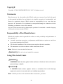
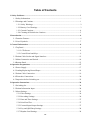
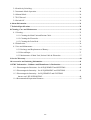
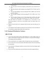
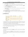
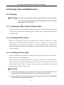
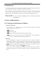
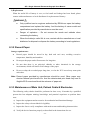
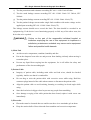
1
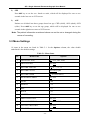
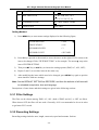
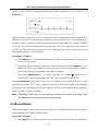
EDAN INSTRUMENTS, INC. SE-1 Version No.: V1.1 Release Date: Sep.2007 Part No.: MS1R-19929-V1.1 EC Declaration of Conformity Manufacturer: EDAN Instruments, Inc. Addr: 3/F - B, Nanshan Medical Equipments Park, Nanhai Rd 1019#, shekou, Nanshan Shenzhen, 518067 P.R. China European Representative: Shanghai International Holding Corp. GmbH (Europe) Addr: Eiffestrasse 80 D-20537 Hamburg Germany Product: Electrocardiograph Model: SE-1 Classification (MDD, Annex IX): Class II a, Rule 10 According To Annex IX of the MDD We herewith declare that the above mentioned product(s) meet the transposition into national law, the provisions of Council Directive 93/42/EEC of 14 June 1993 concerning medical devices - as amended by Directive 98/79/EC on in vitro diagnostic medical devices. All supporting documentation is retained at the premises of the manufacturer. DIRECTIVES General Applicable Directives: Medical Device Directive: COUNCIL DIRECTIVE 93/42/EEC of 14 June 1993 concerning medical devices (MDD 93/42/EEC). Standards applied: EN ISO14971: 2000, EN 60601-1: 1988, EN 60601-2-25: 1995, EN 60601-1-4: 1997, EN 60601-1-2: 2001, EN 60601-2-51: 2003, EN 1041: 1998, IEC/TR 60878-2003, EN 980: 1997, EN 60417-2-2000, ISO1000: 1998, EN ISO780: 1999. Notified Body: TÜV SÜD Product Service GmbH, Ridlerstr 65, D-80339 MÜnchen, Germany. Identification number -I- Copyright Copyright © EDAN INSTRUMENTS, INC. 2007. All rights reserved. Statements Edan Instruments, Inc. (hereinafter called EDAN) makes no warranty of any kind with regard to this material, including, but not limited to the implied warranties of merchantability and fitness for a particular purpose. EDAN assumes no responsibility for any errors that may appear in this document, or for incidental or consequential damage in connection with the furnishing, performance or use of this material. No part of this document can be photocopied, reproduced or translated to another language without prior written consent of EDAN. Responsibility of the Manufacturer EDAN only considers itself responsible for effects on safety, reliability and performance of the equipment if: ♦ Assembly operations, extensions, re-adjustments, modifications or repairs are carried out by personnel authorized by EDAN; ♦ The electrical installation of the relevant room complies with safety standards; ♦ The instrument is used in accordance with the instructions for use. Note: This device is not intended for home use. WARNING : This device is not intended for treatment. Using This Label Guide WARNING A WARNING label advises against certain actions or situations that could result in personal injury or death. CAUTION A CAUTION label advises against actions or situations that could damage equipment, produce inaccurate data, or invalidate a procedure. Note: A NOTE provides useful information about a function or procedure. -II- Table of Contents 1 Safety Guidance...........................................................................................................................1 1.1 Safety Information...............................................................................................................1 1.2 Warnings and Cautions........................................................................................................1 1.2.1 Safety Warnings ........................................................................................................2 1.2.2 Battery Care Warnings ..............................................................................................3 1.2.3 General Cautions .......................................................................................................4 1.2.4 Cleaning & Disinfection Cautions ............................................................................5 2 Introduction .................................................................................................................................6 2.1 Function Features ................................................................................................................6 2.2 List of Symbols ...................................................................................................................7 3 General Information ...................................................................................................................8 3.1 Top Panel.............................................................................................................................8 3.1.1 LCD Screen ...............................................................................................................8 3.1.2 Control Panel and Keys.............................................................................................9 3.2 Patient Cable Socket and Signal Interface ........................................................................12 3.3 Mains Connection and Switch...........................................................................................14 3.4 Bottom Panel .....................................................................................................................15 4 Operation Preparations ............................................................................................................17 4.1 Power Supply ....................................................................................................................17 4.2 Loading/Replacing Record Paper......................................................................................18 4.3 Patient Cable Connection..................................................................................................19 4.4 Electrodes Connections .....................................................................................................20 4.5 Inspection before Switching on.........................................................................................22 5 Operation Instructions..............................................................................................................24 5.1 Switching On.....................................................................................................................24 5.2 Patient Information Input ..................................................................................................24 5.3 Menu Settings....................................................................................................................25 5.3.1 Filter Settings ..........................................................................................................26 5.3.2 Recording Settings ..................................................................................................26 5.3.3 Date and Time Settings ...........................................................................................27 5.3.4 Print Head Test ........................................................................................................27 5.3.5 External Input/Output Settings................................................................................27 5.3.6 Key and QRS Beep Settings....................................................................................28 5.3.7 Rhythm Lead Settings .............................................................................................28 -III- 5.4 Sensitivity Switching.........................................................................................................28 5.5 Automatic Mode Operation...............................................................................................28 5.6 Manual Mode ....................................................................................................................29 5.7 ECG Record ......................................................................................................................30 5.8 Switch Off .........................................................................................................................30 6 Alarm Information ....................................................................................................................31 7 Technical Specifications ............................................................................................................32 8 Cleaning, Care and Maintenance ............................................................................................35 8.1 Cleaning ............................................................................................................................35 8.1.1 Cleaning the Main Unit and Patient Cable..............................................................35 8.1.2 Cleaning the Electrodes...........................................................................................35 8.1.3 Cleaning the Print Head ..........................................................................................35 8.2 Disinfection .......................................................................................................................36 8.3 Care and Maintenance.......................................................................................................36 8.3.1 Recharge and Replacement of Battery....................................................................36 8.3.2 Record Paper ...........................................................................................................37 8.3.3 Maintenance of Main Unit, Patient Cable & Electrodes .........................................37 9 Service Warranty.......................................................................................................................40 10 Accessories and Ordering Information .................................................................................41 11 EMC Information - Guidance and Manufacture’s Declaration..........................................42 11.1 Electromagnetic Emissions - for all EQUIPMENT and SYSTEMS...............................42 11.2 Electromagnetic Immunity - for all EQUIPMENT and SYSTEMS ...............................43 11.3 Electromagnetic Immunity - for EQUIPMENT and SYSTEMS that are not LIFE-SUPPORTING..................................................................................44 11.4 Recommended Separation Distances ..............................................................................45 -IV- SE-1 Single Channel Electrocardiograph User Manual 1 Safety Guidance 1.1 Safety Information The design of the single channel electrocardiograph complies with the international standard IEC 60601-1 Medical Electrical Equipment: General Requirements for Safety and IEC 60601-2-25 Particular Requirements for the Safety of Electrocardiographs etc. The classification of this equipment is Class І, type CF, which means a higher degree of protection against electric shock, and the patient connection is fully isolated. Furthermore it is defibrillation-proof. This equipment is not explosion-proof. Do not use it in the presence of flammable anesthetics. This equipment is designed for continuous operation and is ‘ordinary’ (i.e. not drip or splash-proof). Classification: 1) Anti-electric-shock type: Class І with internal power supply 2) Anti-electric-shock degree: CF (with defibrillation-proof applied part) 3) Degree of protection against harmful ingress of water: Ordinary equipment (Sealed equipment without liquid proof) 4) Disinfection/sterilization method: Refer to this user manual for details 5) Safety degree of application in the presence of flammable gas: Equipment not suitable for use in the presence of flammable gas 6) Working Mode: Continuous operation 7) EMC: Group І, Class A 1.2 Warnings and Cautions In order to use the electrocardiograph safely and effectively, avoiding possible dangers caused by improper operations, please read through the user manual and be sure to be familiar with all functions of the equipment and proper operation procedures before use. Please pay more attention to the following warning and caution information. -1- SE-1 Single Channel Electrocardiograph User Manual 1.2.1 Safety Warnings WARNING ♦ : The electrocardiograph is provided for the use of qualified physicians or personnel professionally trained. And they should be familiar with the contents of this user manual before operation. ♦ Only qualified service engineers can install this equipment. And only service engineers authorized by EDAN can open the shell. ♦ Only qualified installation or service engineers can shift the mains shift switch (100V~115V/220V~240V) according to local mains supply. ♦ The results given by the equipment should be examined with respect to the overall clinical condition of the patient. And it can not substitute for regular checking. WARNING ♦ : EXPLOSION HAZARD-Do not use the electrocardiograph in the presence of flammable anesthetic mixture with oxygen or other flammable agents. ♦ SHOCK HAZARD-The power receptacle must be a hospital grade grounded outlet. Never try to adapt the three-prong plug to fit a two-slot outlet. ♦ If the integrity of external protective conductor in installation or arrangement is in doubt, the equipment should be operated from the built-in rechargeable battery. ♦ Do not use this equipment in the presence of high static electricity or high voltage equipment which may generate sparks. ♦ This equipment is not designed for internal use and direct cardiac application. WARNING ♦ : Only patient cable and other accessories supplied by EDAN can be used. Or else, the performance and electric shock protection can not be guaranteed. ♦ Be sure that all electrodes have been connected to the patient correctly before operation. ♦ Be sure that the conductive parts of electrodes and associated connectors, including neutral electrode, should not contact with earth or any other -2- SE-1 Single Channel Electrocardiograph User Manual conducting objects. ♦ Electrodes with defibrillation protection should be used while defibrillating. ♦ There is no danger for patients with pacemaker. ♦ Do not touch the patient, bed, table and the equipment while using defibrillator or pacemaker simultaneously. ♦ In order to avoid burning, please keep the electrode far away from the radio knife while using electrosurgical equipment simultaneously. WARNING ♦ : Accessory equipment connected to the analog and digital interfaces must be certified according to the respective IEC standards (e.g. IEC 60950 for data processing equipment and IEC 60601-1 for medical equipment). Furthermore all configurations shall comply with the valid version of the standard IEC 60601-1-1. Therefore anybody, who connects additional equipment to the signal input connector or output connector to configure a medical system, must make sure that it complies with the requirements of the valid version of the system standard IEC 60601-1-1. If in doubt, consult our technical service department or your local distributor. ♦ The summation of leakage current should never exceed leakage current limits while several other units are used at the same time. ♦ The potential equalization conductor can be connected to that of other equipment when necessary, to make sure that all these equipment are connected with the potential equalization bus bar of the electrical installation. 1.2.2 Battery Care Warnings WARNING ♦ : Improper operation may cause the battery to be hot, ignited or exploded, and it may lead to the declination of battery’s capacity. It is necessary to read the user manual carefully and pay more attention to warning messages. ♦ Only qualified service engineer authorized by EDAN can open the battery compartment and replace the battery. And the battery of same model and specification provided by manufacturer should be used. ♦ Danger of explosion -- Do not reverse the anode and cathode when connecting -3- SE-1 Single Channel Electrocardiograph User Manual the battery. ♦ Do not heat or splash the battery or throw it into fire or water. ♦ When leakage or foul smell found, stop using the battery immediately. If your skin or cloth comes into contact with the leakage liquid, cleanse it with clean water at once. If the leakage liquid splashes into your eyes, do not wipe them. Irrigate them with clean water first and go to see a doctor immediately. ♦ When the battery’s useful life is over, contact with the manufacturer or local distributor for disposal or dispose the battery according to local regulations. 1.2.3 General Cautions CAUTION ♦ : A void liquid splash and excessive temperature. The temperature must be kept between 5℃ and 40℃ while working. And it should be kept between -20 ℃ and 50℃ during transportation, and between -10 ℃ and 40℃ during storage. ♦ Do not use the equipment in dusty environment with bad ventilation or in the presence of corrosive. ♦ Be sure that there is no intense electromagnetic interference source around the equipment, such as radio transmitter or mobile phone etc. Attention: large medical electrical equipment such as electrosurgical equipment, radiological equipment and magnetic resonance imaging equipment etc. are likely to bring electromagnetic interference. CAUTION ♦ : Before use, the equipment, patient cable and electrodes etc. should be checked. Replacement should be taken if there is any evident defectiveness or aging symptom which may impair the safety or performance. ♦ The following safety checks should be performed at least every 24 months by a qualified person who has adequate training, knowledge, and practical experience to perform these tests. a) Inspect the equipment and accessories for mechanical and functional damage. b) Inspect the safety relevant labels for legibility. c) Inspect the fuse to verify compliance with rated current and breaking -4- SE-1 Single Channel Electrocardiograph User Manual characteristics. d) Verify the device functions properly as described in the instructions for use. e) Test the protection earth resistance according IEC 601-1/1988: Limit 0.2 ohm. f) Test the earth leakage current according IEC 601-1/1988: Limit: NC 500 uA, SFC 1000uA. g) Test the patient leakage current according IEC 601-1/1988: Limit: 10 uA (CF). h) Test the patient leakage current under single fault condition with mains voltage on the applied part according IEC 601-1/1988: Limit: 50uA (CF). The data should be recorded in an equipment log. If the device is not functioning properly or fails any of the above tests, the device has to be repaired. ♦ Ruptured fused must only be replaced with the same type and rating as the original. ♦ The equipment and reusable accessories can be sent back to the manufacturer for recycling or proper disposal after their useful lives. 1.2.4 Cleaning & Disinfection Cautions CAUTION ♦ : Turn off the power before cleaning and disinfection. If mains supply used, the power cord should be drugged out of the outlet also. And prevent the detergent from seeping into the equipment. ♦ Do not immerse the unit or patient cable into liquid under any circumstances. ♦ Do not clean the unit and accessories with abrasive fabric and avoid scratching the electrodes. ♦ Any remainder of detergent should be removed from the unit and patient cable after cleaning. ♦ Do not use chloric disinfectant such as chloride and sodium hypochlorite etc. -5- SE-1 Single Channel Electrocardiograph User Manual 2 Introduction SE-1 single channel electrocardiograph is a single channel digital ECG (electrocardiograph) recorder with high performance. One channel cardiogram can be previewed on the LCD (liquid crystal display) screen, and it can be recorded by high-quality thermal printer. Moreover, real-time heart rate can be displayed on the screen which can also be printed out on the record. Manual recording mode and four automatic recording modes can be chosen conveniently. Either mains supply or built-in rechargeable Lithium battery can be used as power supply. Configurations: Main unit and accessories, including patient cable, chest electrodes, limb electrodes, thermal print paper and power cord etc. Intended use: The cardiogram and heart rate recorded by the electrocardiograph can help doctors to analysis and diagnose heart disease or arrhythmia in hospitals. And its compact size makes it suitable for use while visiting patients at home. Note: It is not designed for internal use and direct cardiac application. 2.1 Function Features ♦ Low weight and compact size ♦ Touch key for easy operation ♦ LCD for single channel ECG preview before recording ♦ Four automatic recording modes and manual mode optional ♦ General menu for recording parameters setting ♦ Built-in rechargeable Lithium battery with high capacity ♦ Alarm information for lead off, lack of paper and weak battery etc. ♦ Thermal dot-matrix printer for high-resolution printout ♦ Automatic adjustment of baseline for optimal recording ♦ Selectable printing formats, standard single channel or single channel & rhythm lead ♦ Standard external input/output interface and RS232 communication interface for linking to special network and setting up ECG database -6- SE-1 Single Channel Electrocardiograph User Manual 2.2 List of Symbols External output External input Equipment or part of CF type with defibrillation proof Attention – general warning (see accompanying document) Potential equalization Mains supply (or indicator) On (mains supply) Off (mains supply) Battery indicator Battery recharging indicator -7- SE-1 Single Channel Electrocardiograph User Manual 3 General Information LCD Screen Smart ECG SE-1 USB Interface Record Paper External Recorder Input/Output Socket RS232 Socket Control Panel Patient Cable Socket Figure 3-1 Main Unit (trademark) Smart ECG (trade name) SE-1 (model) (classification symbol, equipment of CF type with defibrillation proof) 3.1 Top Panel 3.1.1 LCD Screen The LCD screen can be revolved and settled firmly in different angle. Normally, the contents displayed on the LCD screen include: (described from left to right in row order) -8- SE-1 Single Channel Electrocardiograph User Manual First Row: ♦ Operation mode (AUTO1, AUTO2, AUTO3, AUTO4 and MANU) ♦ II stop symbol, which will turn to ♦ Warning message (LD OFF, or PAPER? etc.) ♦ Current time while recording Second Row: ♦ Current lead (І, П, Ш, AVR, AVL, AVF, V1, V2, V3, V4, V5, V6) ♦ Heart rate (--, actual heart rate, or OVR message) Third Row: ♦ Filter setting (FLT = AC, EMG, ALL, OFF) ♦ ECG Fourth Row: ♦ Sensitivity (×1, ×2, AGC, · 25, · 5) ♦ Paper speed (25, 50) ♦ Battery capacity symbol ( ♦ Display the ID, sex (M/F) and age group (CHD/ADL/OLD) while setting; and , , , ) “BATTERY WEAK” will be showed here when the battery capacity is weak. 3.1.2 Control Panel and Keys -9- SE-1 Single Channel Electrocardiograph User Manual 1) Indicator Mains supply indicator: when mains supply is used, the indicator will be lit. Battery indicator: when the built-in rechargeable lithium battery is used, the indicator will be lit. Battery recharging indicator: both the battery recharging indicator and mains supply indicator will be lit after the mains power switch has been turned on. After ON/OFF key being pressed, the battery recharging indicator will be black if the battery capacity is full. However, if the battery capacity is not full, the battery recharging indicator will be lit until the battery is full recharged, and after that the battery recharging indicator will be black. 2) SENS (Sensitivity Switch Key) The sensitivity switching order: ×1 → ×2 → AGC → · 25 → · 5 The ECG signal range which can be measured and recorded is different according to different sensitivity, as the following list shows. Options Sensitivity Signal range measured ×1 10mm/mV -2.5mV ~ +2.5mV ×2 20mm/mV -1.25mV ~ +1.25mV AGC Auto Gain Control Adjust sensitivity automatically · 25 2.5mm/mV -10mV ~ +10mV ·5 5mm/mV -5mV ~ +5mV If the fluctuating range of the ECG signal is great, ‘AGC’ would be better to be chosen for the sensitivity can be adjusted automatically under this mode. 3) RESET (Lead Locking Key) Press this key to lock the lead while ECG recording. After that, the corresponding ECG will be a line. It is always used to draw the baseline to zero quickly in the case of baseline excursion in actual ECG recording. The lead will be unlocked automatically after 0.4 -10- SE-1 Single Channel Electrocardiograph User Manual seconds. 4) 1mV Calibration Key Under manual mode, this key can be pressed to record a 1mV calibration pulse at any time while recording and the ECG trace will re-center. 5) MODE (Mode Switch Key) There are four automatic modes and a manual mode. This key can be pressed to select recording mode. The switching order of leads in each mode is listed in Table 3-1. Table 3-1 Lead Switching order of Different Mode Mode Switching Order (from left to right) MANU І П Ш AVR AVL AVF V1 V2 V3 V4 V5 V6 AUTO1 І П Ш AVR AVL AVF V1 V2 V3 V4 V5 V6 AUTO2 AVL І AVR П AVF Ш V1 V2 V3 V4 V5 V6 AUTO3 І AVR V1 V4 П AVL V2 V5 Ш AVF V3 V6 AUTO4 2 channel automatic mode (AUTO1 + Rhythm Lead) 6) LEAD (Lead Switch Key) Under manual mode, press the key to switch the lead in order. 7) PRINT/STOP Key Used to begin recording and stop recording. -11- SE-1 Single Channel Electrocardiograph User Manual 8) ON/OFF Key When the unit has been powered on, press this key to turn on or turn off the electrocardiograph. 9) MENU Key Press MENU key to enter menu settings interface. 10) ID Setting Key These two ID keys can be pressed to set the patient’s ID number. Press the upward arrow key to increase ID number while press the downward arrow to decrease ID number on the basis of current ID number. 11) M/F Press M/F key to choose sex, male (M) or female (F). 12) AGE Press AGE key to set age: child (CHD), adult (ADL) or elder (OLD). 3.2 Patient Cable Socket and Signal Interface There are sockets including the patient cable socket, RS232 socket, external input/output socket and USB interface (reserved) at the right side of the main unit as Figure 3-1 shows. 1) Patient Cable Socket -12- SE-1 Single Channel Electrocardiograph User Manual : Defibrillation-proof applied part of type CF : Attention – see accompanying document Definition of corresponding pins: Pin Signal Pin Signal Pin Signal 1 C2 (input) 6 N or RF (input) 11 F (input) 2 C3 (input) 7 NC 12 NC 3 C4 (input) 8 NC 13 NC 4 C5 (input) 9 R (input) 14 N or RF (input) 5 C6 (input) 10 L (input) 15 NC 2) RS232 Socket WARNING : RS232 interface is 1500V AC isolated intensity and the maximum voltage applied should not exceed +15V DC. Definition of corresponding pins: Pin Signal Pin Signal Pin Signal 1 NC 4 NC 7 NC 2 RxD (input) 5 GND 8 NC 3 TxD (output) 6 NC 9 NC 3) External Input/Output Socket -13- SE-1 Single Channel Electrocardiograph User Manual Definition of corresponding pins: Pin Signal Pin Signal 1 GND 4 GND 2 GND 5 ECG Signal (input) 3 GND 6 ECG Signal (output) 4) USB Interface (Reserved) WARNING ♦ : Accessory equipment connected to the interfaces must be certified according to the respective IEC standards (e.g. IEC60950 for data processing equipment and IEC 60601-1 for medical equipment). Furthermore all configurations shall comply with the valid version of the standard IEC 60601-1-1. Therefore anybody, who connects additional equipment to the input or output connector to configure a medical system, must make sure that it complies with the requirements of the valid version of the system standard IEC 60601-1-1. If in doubt, consult our technical service department or your local distributor. ♦ The summation of leakage current should never exceed leakage current limits while several other units are used at the same time. 3.3 Mains Connection and Switch Potential Equalization Conductor Mains Power Switch Mains Supply Socket At the left side of the main unit, there is the mains supply socket, power switch and potential equalization conductor as the above figure shows. 1) Potential Equalization Conductor Potential equalization conductor provides a connection between the unit and the potential equalization bus bar of the electrical installation when necessary. -14- SE-1 Single Channel Electrocardiograph User Manual 2) Mains Supply Socket AC SOURCE: alternating current supply socket 3) Power Switch : Switch on the mains power supply : Switch off the mains power supply 3.4 Bottom Panel Mains Supply Shift Switch Battery Compartment Fuse Fuse Label Label on Bottom 1) Battery Compartment The battery label indicates the rated voltage and rated capacity of rechargeable Lithium battery pack. Rated voltage: 14.4V, Rated capacity: 1600mAh. Attention – general warning (see accompanying document) WARNING : Only qualified service engineer authorized by EDAN can open the battery compartment and replace the battery. And the battery of same model and specification provided by manufacturer must be used. 2) Mains Supply Shift Switch Mains supply with rated input voltage 230V (220V~240V) or 115V (100V~115V) can be -15- SE-1 Single Channel Electrocardiograph User Manual chosen by the shift switch according to local mains supply specification. WARNING : Only qualified installation or service engineer can shift the mains shift switch according to local mains supply. 3) Fuse There are two same fuses installed on the bottom of the main unit. The specification is showed on the fuse label: AC220V-240V: T200mA; AC100V-115V: T400mA; Φ5×20. WARNING : Ruptured fused must only be replaced with the same type and rating as the original. -16- SE-1 Single Channel Electrocardiograph User Manual 4 Operation Preparations CAUTION : Before use, the equipment, patient cable,electrodes and other accessories should be checked. Replace it if there is any evident defectiveness or aging which may impair the safety or performance. And be sure that the equipment is in proper working condition. 4.1 Power Supply WARNING : If the integrity of external protective conductor in installation or arrangement is in doubt, the equipment should be operated from the built-in rechargeable battery. The electrocardiograph can be powered either by mains supply or the built-in rechargeable lithium battery pack. 1) Mains supply The mains connection socket is on the left of the unit. If mains supply used, connect the power cord to the socket first, and then connect the plug of the cord to the hospital grade outlet. Rated input voltage: 100V~115V or 220V~240V Rated frequency: 50Hz/60Hz Rated input power: 35VA Make sure the mains supply meets the above requirements before power on. And then press the mains power switch to power on the unit. Then the mains supply indicator ( ) will be lit as well as the battery recharging indicator ( ). If the built-in rechargeable battery is weak when mains supply used, the battery recharging indicator will be still lit after ON/OFF key pressed, which means the battery is recharged. If the battery capacity if full, the recharging indicator will be black after ON/OFF key pressed. 2) Built-in rechargeable battery While the built-in rechargeable lithium battery pack used, turn on the unit by pressing ON/OFF key on control panel directly and the battery indicator ( The battery symbol ) will be lit. will be displayed on the LCD screen. Because of the consumption during storage and transport, the capacity of battery may not be full. If the symbol and the alarm information “BATTERY WEAK” are displayed, which means the battery -17- SE-1 Single Channel Electrocardiograph User Manual capacity is weak. And in this circumstance please recharge the battery first. Note: Please refer to the maintenance section for how to recharge the battery. During recharging the battery, the electrocardiograph can be powered by mains supply at the same time. WARNING : Potential equalization conductor of the unit should be connected to the potential equalization bus bar of the electrical installation when necessary. 4.2 Loading/Replacing Record Paper Rolled thermal paper with 50mm width is used as ECG record paper. When there is no record paper loaded or it reaches the end of record paper, warning message “PAPER?” will be given on the LCD screen. Under this circumstance, record paper should be loaded or replaced immediately. Casing Paper Roller Thermal Print Head Scale Roller Pin Printer Platen Groove Paper Tray Loading/Replacing Procedures: 1) Place fingers under the flange of the recorder casing, pull upwards directly to release the casing; 2) Take out the paper roller, and remove remain paper from the left of roller if necessary; 3) Take off the wrapper of the new thermal paper roll, and then put through the roller from the left with the paper’s grid side facing downward. 4) Then place the paper and roller gently in the paper tray with the roller pin on the roller’s left side facing to the groove; -18- SE-1 Single Channel Electrocardiograph User Manual 5) Pull about 2cm of the paper out, and put down the recorder casing with the paper’s side edges in parallel with the scale on the surface of casing; 6) Secure the casing by pressing it firmly. 4.3 Patient Cable Connection Patient cable includes two parts, main cable and lead wires with associated electrode connectors. The electrode connectors can be distinguished from the color and identifier on them. Model of Patient Cable Main Cable Lead Wires Label of Patient Cable Electrode Connectors Connector Connect Main Cable: Plug the connector of main cable into the patient cable socket on the right side of the unit, and secure the screw. WARNING ♦ : This product is CF classified and defibrillation protected only when the original patient cable is used. However, as a safety precaution when possible, remove electrodes before defibrillation. ♦ Precautions must be observed when using high frequency devices. Use the special high frequency EDAN patient cable to avoid possible signal interference during ECG acquisition. -19- SE-1 Single Channel Electrocardiograph User Manual 4.4 Electrodes Connections Chest Electrode: Suction Bulb Electrode Metal Cup Limb Electrode: Electrode Reed Clamp The identifier and color code of electrodes used complies with IEC requirements. In order to avoid incorrect connections, the electrode identifier and color code is specified in Table 4-1. Moreover the equivalent code according to American requirements is given too. Table 4-1 Electrodes, Identifier and Color Code European Electrodes Identifier American Color code Identifier Color code Right arm R Red RA White Left arm L Yellow LA Black Right leg N or RF Black RL Green Left leg F Green LL Red Chest 1 C1 White/red V1 Brown/red Chest 2 C2 White/yellow V2 Brown/yellow Chest 3 C3 White/green V3 Brown/green Chest 4 C4 White/brown V4 Brown/ blue Chest 5 C5 White/black V5 Brown/orange Chest 6 C6 White/violet V6 Brown/violet -20- SE-1 Single Channel Electrocardiograph User Manual As the following figure shows, the chest electrodes’ position on body surface is C1 C4 C2 C6 C3 C5 C1: Fourth intercostals space at right border of sternum C2: Fourth intercostals space at left border of sternum C3: Fifth rib between C2 and C4 C4: Fifth intercostals space on left midclavicular line C5: Left anterior axillary line at the horizontal level of C4 C6: Left midaxillary line at the horizontal level of C4 The contacting resistance between the patient and the electrode will affect the quality of ECG greatly. In order to get a high-quality ECG, the skin/electrode resistance must be minimized while connecting electrodes. Chest electrodes connection: 1) Ensure the electrodes to be clean firstly; 2) Align all lead wires of patient cable to avoid twisting, and connect the associated electrode connectors with corresponding electrodes according to the color and identifier; 3) Clean electrode area on chest surface with alcohol; 4) Daub the round area of 25mm diameter on each electrode site with gel evenly; 5) Place a small mount of gel on the brim of chest electrode’s metal cup; 6) Place the electrode on chest electrode site and squeeze the suction bulb. Unclench it and then the electrode is adsorbed on chest. Attach all chest electrodes in the same way. Limb electrodes connection: 1) Ensure the electrodes to be clean firstly; 2) Align lead wires of patient cable to avoid twisting, and connect the electrode connectors -21- SE-1 Single Channel Electrocardiograph User Manual to corresponding electrodes according to the color and identifier; 3) Clean electrode area on a short distance above the ankle or wrist with alcohol; 4) Daub the electrode area on limb with gel evenly; 5) Place a small amount of gel on the metal part of limb electrode clamp; 6) Connect the electrode to limb, and be sure that the metal part be placed on the electrode area above the ankle or wrist. Attach all limb electrodes in the same way. WARNING ♦ : Be sure that all electrodes have been connected to the patient correctly before operation. ♦ Be sure that the conductive parts of electrodes and associated connectors, including neutral electrode, should not contact with earth or any other conducting objects. ♦ There is no danger when using the electrocardiograph with electrical stimulation equipment. However, the stimulation units should only be used at a sufficient distance from the electrodes .If in doubt, the patient should be disconnected from the device. ♦ Electrodes with defibrillation protection should be used while defibrillating. ♦ Do not touch the unit casing during defibrillation. 4.5 Inspection before Switching on In order to avoid safety hazards and get good ECG record, the following inspection procedures are recommended before turning on the unit and beginning operation. 1) Environment: ♦ Check and make sure that there is no electromagnetic interference source around the equipment, especially large medical electrical equipment such as electrosurgical equipment, radiological equipment and magnetic resonance imaging equipment etc. Switch off these devices when necessary. ♦ Keep the examination room warm to avoid muscle action voltages in ECG signal caused by cold. 2) Power Supply: ♦ If mains power used, please check whether the power cord has been connected to the unit well. And the grounded three-phase outlet should be used. -22- SE-1 Single Channel Electrocardiograph User Manual ♦ Recharge the battery first before use when the battery capacity is weak. 3) Patient Cable: ♦ Check whether the patient cable has been connected to the unit firmly, and keep it far away from the power cord. 4) Electrodes: ♦ Check whether all electrodes have been connected to lead wires of patient cable correctly according to the identifier and color. ♦ Be sure that all electrodes have been connected to the patient correctly. ♦ Ensure that the chest electrodes haven’t contacted with each other. 5) Recorder Paper: ♦ Ensure that there is enough recorder paper loaded correctly. ♦ Make sure the case of the recorder has been secured. 6) Patient: ♦ The patient should not contact with conducting object such as earth, and metal part of bed etc. ♦ Ensure the patient is warm and relaxed, and breathe calmly. WARNING : The electrocardiograph is provided for the use of qualified physicians or personnel professionally trained. And they should be familiar with the contents of this user manual before using. -23- SE-1 Single Channel Electrocardiograph User Manual 5 Operation Instructions 5.1 Switching On ♦ While mains supply used, press the power switch on the left side of the unit first, and the mains supply indicator ( ) is lit. Then press ON/OFF key on the control panel to turn on the unit. Equipment information such as name, manufacturer and version etc., will be displayed on LCD screen after self-test. Then the electrocardiograph is ready for examination and recording. ♦ While built-in rechargeable lithium battery used, press ON/OFF key on the control panel directly to turn on the unit, and then the battery indicator ( ) is lit. After self-test, the electrocardiograph is ready for examination and recording. 5.2 Patient Information Input II AUTO 1 І 10 : 50 NO FLT = ALL ×1 25 1) ECG256 MALE ADL ID Number Press ID (upward arrow) key to increase ID number or ID (downward arrow) to decrease it on the basis of current number. The number will be displayed for one or two seconds in the last row on LCD screen such as ‘ECG 256’ in the above figure. Under the following circumstances, the ID number may increase automatically: ♦ Under automatic recording mode, PRINT/STOP key can be pressed to record the ECG automatically. When one full lead ECG record finished, or PRINT/STOP key is pressed during the recording course, the ID number will automatically increase one when begin recording again. ♦ Under manual recording mode, press PRINT/STOP key to record ECG. If PRINT/STOP key is pressed during the course of recording, the ID number will automatically increase one when begin recording again. -24- SE-1 Single Channel Electrocardiograph User Manual 2) SEX Press M/F key to set the sex: female or male, which will be displayed for one or two seconds in the last row on LCD screen. 3) AGE Patients are divided into three groups based on age: CHD (child), ADL (adult), OLD (elder). Press AGE key to set the age group, which will be displayed for one or two seconds in the right down corner of LCD screen. Note: The patient information mentioned above can not be set or changed during the course of recording. 5.3 Menu Settings 19 items in the menu are listed in Table 5-1. In the Options column, the value double underlined is the default settings. Table 5-1 Menu Items No. Menu Items Options 1 FILTER SETTING AC, ALL, OFF, EMG 2 PWAVE START ON, OFF 3 RECORD LENGTH 2, 3, 4, …, 11, 12 4 RECORD COUNT SECOND, QRS 5 RECORD SPEED 25, 50 (unit: mm/s) 6 HEARTRATE PRINT ON, OFF 7 YEAR 0~99 8 MONTH 1~12 9 DAY 1~31 10 HOUR 0~23 11 MINUTE 0~59 12 PRINT HEAD TEST ON, OFF 13 DEFAULT SETTING NO, RESTORE 14 EXTINPUT RECORD ON, OFF 15 KEY BEEP ON, OFF -25- SE-1 Single Channel Electrocardiograph User Manual 16 QRS BEEP ON, OFF 17 RHYTHM LEAD І, П, Ш, AVR, AVL, AVF V1, V2, V3, V4, V5, V6 18 LOWPASS FILTER NO, 75HZ, 100HZ, 150HZ 19 LANGUAGE ENG, CHN Setting Method: 1) Press MEMU key to enter menu settings displayed as the following figure; FILTER SETTING : ALL PWAVE START : ON RECORD LENGTH :3 RECORD COUNT : SECOND 2) Press ID key (upward or downward) to move the arrow at the right of LCD screen to the item to be changed. Take ‘FILTER SETTING’ as for example. The arrow item of FILTER SETTING. stop at the 3) Then press M/F key or AGE key to choose the setting options (EMG, AC, ALL, OFF); 4) Repeat 2) and 3) to set other items in the same way; 5) After modifying the items which need to be changed, press MENU key again to quit the menu interface with new settings. Note: Set the DEFAULT SETTING as RESTORE, and then the defaults of all items will be reloaded except date, time and language. Descriptions of some items and their settings are given in the following sections. 5.3.1 Filter Settings The filter can be chosen among EMG, AC, ALL (both of EMG and AC) or OFF (no filter). When choose OFF, the filter will not work. Generally, ALL is recommended to be set in order to get better ECG record. 5.3.2 Recording Settings Recording settings includes start, length, count unit, speed and contents. Such as: -26- SE-1 Single Channel Electrocardiograph User Manual PWAVE START : ON RECORD LENGTH :3 RECORD COUNT : SECOND RECORD SPEED : 25 HEARTRATE PRINT : ON Take the above settings as example, the ECG will be recorded from P wave, and the printing speed is 25mm/s. The record length of each lead is 3 seconds. And the heart rate will be printed out at the bottom of each lead recording beginning. When QRS is taken as recording count unit, the record length will be 3 periods of QRS wave. Note: The record duration of each lead must be longer than 2 seconds. So when QRS is chosen to be the count unit, no matter how long the record length is, if the period of QRS wave is too short, the electrocardiograph will keep recording for 2 seconds. 5.3.3 Date and Time Settings The date and time on LCD screen and ECG record can be set in the following items: YEAR :4 MONTH :8 DAY :6 HOUR : 14 MINUTE : 25 As the above settings, the date & time is Aug. 6th, 2004, 14:25 PM. And it will be printed out as 2004-8-6-14:25 on the record. 5.3.4 Print Head Test PRINT HEAD TEST : OFF Print head test is used to check whether the print head can work normally or not. The default status of print head test is OFF. Turn on this item when the print paper has been loaded. Then the triangle wave in effective paper width will be printed out. The status of print head can be estimated from this triangle wave. 5.3.5 External Input/Output Settings External input/output signal interface is equipped in the electrocardiograph, through which -27- SE-1 Single Channel Electrocardiograph User Manual ECG signal from external equipment can be received, and ECG signal detected by the electrocardiograph can be transmitted to other external equipment. Set the EXTINPUT RECORD as ON to turn on the function and OFF to turn off. 5.3.6 Key and QRS Beep Settings KEY BEEP : ON QRS BEEP : OFF When KEY BEEP is ON, a short beep sound will be heard when press the control key. When KEY BEEP is OFF, there is no sound while pressing the key. During the course of ECG recording, if QRS BEEP is ON, the unit will make a short beep sound when an R wave has been detected. So in normal recording, continuous and regular sound of beep will be heard. 5.3.7 Rhythm Lead Settings :П RHYTHM LEAD Under AUTO 4 mode, ECG of one channel and a rhythm channel lead can be recorded. The rhythm lead can be anyone of 12 standard leads: І, П, Ш, AVR, AVL, AVF, V1, V2, V3, V4, V5, and V6. 5.4 Sensitivity Switching There are five options of sensitivity: ×1 (10mm/mV) → ×2 (20mm/mV) → AGC → · 25 (2.5mm/mV) → · 5 (5mm/mV) Press key to choose the appropriate sensitivity to achieve better ECG record according to the signal range that can be measured. Refer to Section 3.1.2 for details about signal range under different sensitivity. This key can be pressed during the course of examination or recording under manual mode while it is ineffective during the course of recording under automatic mode. 5.5 Automatic Mode Operation Four automatic recording modes are provided by this electrocardiograph, AUTO 1, AUTO 2, AUTO 3 and AUTO4. Two channels, including a rhythm lead, can be recorded together under -28- SE-1 Single Channel Electrocardiograph User Manual AUTO 4 mode. The lead switching orders under different modes are listed in Table 3-1 in Section 3.1.2. Under automatic mode, leads will be switched in order automatically while recording ECG. That means when ECG signal from one lead has been recorded for the set length such as 3 seconds, it will be switched to the next lead and begin recording another ECG signal. And there is a pause for several seconds before recording the next ECG signal under the modes of AUTO1, AUTO2 and AUTO3. Moreover, a 1mV calibration pulse will be printed on the record automatically before ECG of each lead. Operation Procedures: 1) Press MODE key to choose automatic mode, which will be displayed in the left top corner on LCD screen; 2) If AUTO4 has been chosen, rhythm lead can be selected by pressing MENU key to set RHYTHM LEAD. The rhythm lead can also be set before selecting mode. Moreover there is no pause between different leads while recording. 3) Then press PRINT/STOP key to begin recording. The symbol means ECG is recorded now. It will stop automatically after a full 12-lead ECG printed out. Pressing PRINT/STOP again during the course of recording can stop printing. However, when beginning record later, ECG will be recorded in order from the first lead again. And ID number will increase one automatically. If the ID number needs not to be changed, ID key should be pressed to adjust it before recording. Note: Recording mode can not be changed during the course of printing. Stop recording before choose another recording mode. 5.6 Manual Mode Under manual mode, users can determine the lead to be recorded and set the record settings or other parameters according to different leads. Operation Procedures: 1) Press MODE key to choose MANU mode, which can be discerned by the identifier on -29- SE-1 Single Channel Electrocardiograph User Manual the left corner of LCD screen as MANU; 2) Press LEAD key left arrow or right arrow key to select the lead to be recorded; 3) Press MENU key to set the record settings or other settings. After setting, press MENU key again to confirm the settings; 4) Then press PRINT/STOP key to begin recording; 5) 1mV calibration key can be pressed to print out 1mV pulse wave in the record while ECG recording; 6) Press PRINT/STOP key to stop printing after finishing ECG record. Note: LEAD left and right arrow key can be pressed to switch the lead during the course of recording. 5.7 ECG Record As the above figure shows, the ECG record includes: date and time, ID number, name (written by doctor later), sex, age, sensitivity, paper speed, filter settings, lead name, 1mV calibration pulse, ECG, heart rate, manufacturer and model of the equipment. At the beginning of each lead’s ECG, lead name and 1mV calibration pulse is printed. On the top of the ECG record of each lead, sensitivity is marked. The sensitivity may be different, for it can be changed during the course of recording. 5.8 Switch Off When built-in battery pack used, press ON/OFF key directly to turn off the unit after finishing ECG record. When mains supply used, press ON/OFF key first after finishing ECG record and then switch off the mains supply by pressing the switch on the left side of the unit. Pull off the plug from the outlet last. -30- SE-1 Single Channel Electrocardiograph User Manual 6 Alarm Information Alarm information will be displayed on the LCD screen when there is something wrong. Alarm information provided by the electrocardiograph and corresponding cause is listed in Table 6-1. Table 6-1 Alarm Information and Causes Alarm Information Causes LD OFF Electrodes fall off from the patient or the patient cable falls off from the unit. PAPER? Record paper has not been loaded or it has been used out. BATTERY WEAK The built-in battery is weak. -- The heart rate is over 250BPM. -- The heart rate is below 30BPM. -- Heart rate has not been detected in 2 seconds. OVR The ECG signal exceeds the measuring range under certain sensitivity. -31- SE-1 Single Channel Electrocardiograph User Manual 7 Technical Specifications 1) MDD93/42/EEC 2) IEC60601-1 3) EN 60601-1-4 Safety Standards 4) IEC60601-2-25 5) EN 60601-2-51 6) EN ISO14971 7) EN 55011 8) ANSI/AAMI EC-11 Anti-electric-shock type: Class І with internal power supply Anti-electric-shock degree: Type CF with defibrillation proof Degree of protection harmful ingress of water: Classification Ordinary equipment (Sealed equipment without liquid proof) Disinfection/sterilization method: Refer to the user manual for details Degree of safety of application in the presence of flammable gas: Equipment not suitable for use in the presence of flammable gas Working mode: Continuous operation EMC: Group І, type A Dimensions 288mm×210mm×70mm Weight About 2.3kg Display 192 × 64 pixels color LCD Transport Storage Working -20℃~50℃ -10℃~40℃ 5℃~40℃ Relative 25%~95% 25%~95% 25%~85% Humidity No Condensation No Condensation No Condensation 700hPa ~1060hPa 700hPa ~1060hPa 860hPa ~1060hPa Temperature Environment against Atmospheric Pressure -32- SE-1 Single Channel Electrocardiograph User Manual Rated input voltage =100V~115V/220V~240V Mains Supply Rated frequency = 50/60Hz Rated input power = 35VA Rated voltage = 14.4V Rated capacity = 1600mAh Power Supply Built-in Lithium Battery Charge mode: Constant current/voltage Pack Charge current (standard) = 0.2C5A (320mA) Charge voltage (standard) = (16.8±0.1V) Cycle life ≥ 300 times Power Consumption 35VA Fuse T200mA Ø5×20 or T400mA Ø5×20 Recorder Thermal dot-matrix printer Dot structure: 384 dots/line Thermal Print Head Dot pitch: 0.125mm (8 dots/mm) Dot size: 0.125mm×0.12mm Recording HR Recognition ECG Unit Record Paper Rolled thermal paper Paper Width 50mm Effective Width 48mm Paper Speed 25mm/s, 50mm/s Accuracy ±3% Technique Peak-peak detection HR Range 30BMP~250BMP Accuracy ±1BMP Leads: 12 standard leads Acquisition Mode: One lead -33- SE-1 Single Channel Electrocardiograph User Manual A/D Resolution: 12 digit Time Constant: ≥3.2s Frequency Response: 0.05Hz ~ 150Hz Sensitivity: 2.5, 5, 10, 20 (mm/mV) Input Impedance: ≥10M Ω Input Circuit Current: ≤50nA Input Voltage Range <±5 mVpp Calibration Voltage: 1mV±3% Noise: <15 µ Vp-p EMG Filter: 35Hz (-3dB) Filter AC/DFT Filter: 50Hz/60Hz (-20dB) CMRR >90dB; >100dB (with AC filter) Patient Leakage Current: <10 µ A (220V~240V) Patient Auxiliary Current: <0.1 µ A (DC) Dielectric Strength: 4000V rms External Input (Single ended) ≥100k Ω ; Sensitivity10mm/V±5%; Output (Single ended) ≤100 Ω ; Sensitivity1V/mV±5%; Input/Output (Optional) Communication Interface RS232 (Refer to Section 3.2 for details) -34- SE-1 Single Channel Electrocardiograph User Manual 8 Cleaning, Care and Maintenance 8.1 Cleaning CAUTION : Turn off the power before cleaning and disinfection. If mains supply used, the unit should be switched off first and the power cord should be plugged out of the outlet. 8.1.1 Cleaning the Main Unit and Patient Cable The surface of the main unit and patient cable can be wiped with a clean soft cloth damped in soapy water or non-caustic neutral detergent. After that, remove detergent remainder with a clean dry cloth. 8.1.2 Cleaning the Electrodes Remove the remainder gel from the electrodes with a clean soft cloth first. For chest electrodes, take the suction bulb and mental cup of chest electrodes apart, and for limb electrodes take the clamp and the metal part of the limb electrodes apart. Clean them in warm water and be sure there is no remainder gel. Dry the electrodes with a clean dry cloth or air dry naturally. 8.1.3 Cleaning the Print Head Dirty and soiled thermal print head will deteriorate the record definition. So it should be cleaned at least once a month regularly. Open the recorder casing and remove the record paper. Wipe the print head and printer platen gently with a clean soft cloth damped in 75% alcohol. For stubborn stain, soak it with a little alcohol first and wipe it off with a clean soft cloth. After air dried, load the record paper and shut the casing of the recorder. CAUTION ♦ : Prevent the detergent from seeping into the main unit while cleaning. Do not immerse the unit or patient cable into liquid under any circumstances. ♦ Do not clean the unit and accessories with abrasive fabric and avoid scratching the electrodes and thermal print head. -35- SE-1 Single Channel Electrocardiograph User Manual 8.2 Disinfection To avoid permanent damage to the equipment, disinfection can be performed only when it has been considered as necessary according to your hospital’s regulations. Before disinfection clean the equipment first. Then wipe the surface of the unit and patient cable with 70% isopropyl alcohol. Wipe the surface of electrodes with 70% alcohol or isopropyl alcohol. Never immerse the unit, cable or electrodes into disinfectant solution. CAUTION : Do not use chloric disinfectant such as chloride and sodium hypochlorite etc. 8.3 Care and Maintenance 8.3.1 Recharge and Replacement of Battery 1) Capacity Identification Current capacity of the rechargeable battery can be identified according to the battery symbol in the last row on LCD screen. : Full capacity : Not full but enough : Capacity is limited, and recharge should be taken into account : Battery is weak; and warning message “BATTERY WEAK” will be displayed on LCD screen. The battery should be recharged immediately 2) Recharge The electrocardiograph is equipped with recharge control circuit together with built-in rechargeable lithium battery. Once the main unit is connected to mains supply with power cord, the battery will be recharged automatically. And then the battery recharge indicator ( ) and the mains supply indicator ( ) will be lit at the same time. When the capacity of battery is full, the battery recharge indicator ( ) will be black. Because of the capacity consumption during storage and transport, the capacity of battery is not full while being used at the first time. Battery recharge is recommended before first usage. -36- SE-1 Single Channel Electrocardiograph User Manual 3) Replacement When the useful life of battery is over, or foul smell and leakage has been found, please contact with manufacturer or local distributor for replacement of battery. WARNING ♦ : Only qualified service engineer authorized by EDAN can open the battery compartment and replace the battery. And the battery of same model and specification provided by manufacturer must be used. ♦ Danger of explosion -- Do not reverse the anode and cathode when connecting the battery. ♦ When the battery’s useful life is over, contact with the manufacturer or local distributor for disposal or dispose the battery according to local regulations. 8.3.2 Record Paper Storage requirements: ♦ Record paper should be stored in dry, dark and cool area, avoiding excessive temperature, humidity and sunshine. ♦ Do not put the paper under fluorescence for long time. ♦ Be sure that there is no polyvinyl chloride or other chemicals in the storage environment, which will lead to color change of the paper. ♦ Do not overlap the recorded paper long time, or else the ECG record may trans-print each other. Note: Record paper provided by manufacturer should be used. Other paper may shorten thermal print head’s life. And the deteriorated print head may lead to illegible ECG record and block the advance of paper etc. 8.3.3 Maintenance of Main Unit, Patient Cable & Electrodes The following safety checks should be performed at least every 24 months by a qualified person who has adequate training, knowledge, and practical experience to perform these tests. a) Inspect the equipment and accessories for mechanical and functional damage. b) Inspect the safety relevant labels for legibility. c) Inspect the fuse to verify compliance with rated current and breaking characteristics. d) Verify the device functions properly as described in the instructions for use. -37- SE-1 Single Channel Electrocardiograph User Manual e) Test the protection earth resistance according IEC 601-1/1988: Limit 0.2ohm. f) Test the earth leakage current according IEC 601-1/1988: Limit: NC 500uA, SFC 1000uA. g) Test the patient leakage current according IEC 601-1/1988: Limit: 10uA (CF). h) Test the patient leakage current under single fault condition with mains voltage on the applied part according IEC 601-1/1988: Limit: 50uA (CF). The leakage current should never exceed the limit. The data should be recorded in an equipment log. If the device is not functioning properly or fails any of the above tests, the device has to be repaired. WARNING : Failure on the part of the responsible individual hospital or institution employing the use of this equipment to implement a satisfactory maintenance schedule may cause undue equipment failure and possible health hazards. 1) Main Unit ♦ Avoid excessive temperature, sunshine, humidity and dirt. ♦ Put on the dustproof coat after use and prevent from shaking violently when moving it to another place. ♦ Prevent any liquid from seeping into the equipment, for it will affect the safety and performance of the electrocardiograph. 2) Patient Cable ♦ Integrity of patient cable, including main cable and lead wires, should be checked regularly. And be sure that it is conductible. ♦ Do not drag or twist the patient cable with excessive stress while using. Hold the connector plugs instead of the cable when connect or disconnect the patient cable. ♦ Align the patient cable to avoid twisting, knotting or crooking in closed angle while using. ♦ Store the lead wires in bigger wheel to prevent any people from stumbling. ♦ Once damage or aging of the cable patient has been found, replace it with a new one immediately. 3) Electrodes ♦ Electrodes must be cleansed after use and be sure there is no remainder gel on them. ♦ Keep the suction bulb of chest electrode from sunshine and excessive temperature. -38- SE-1 Single Channel Electrocardiograph User Manual ♦ After long-term use, the surface of electrodes will be oxidized because of erosion and other causes. By this time, electrodes should be replaced to achieve high-quality ECG. CAUTION : The equipment and reusable accessories can be sent back to the manufacturer for recycling or proper disposal after their useful lives. -39- SE-1 Single Channel Electrocardiograph User Manual 9 Service Warranty Material and Manufacture The warranty period for the main unit and the accessories is 12 months from the date of shipment. EDAN warrant that there’s no defect in material and manufacture. During the warranty period, EDAN will repair or replace the defective part free if the defect has been confirmed as material or manufacture defect. Software or Firmware For the software or firmware installed, EDAN will replace the software or firmware free if the defect has been confirmed during 12 months from the date of shipment. But EDAN can not warrant it will not interrupt the use of the product. CAUTION : All services must be done by the engineers authorized by EDAN. Limit of Warranty The charges of freight and others are excluded under warranty. The warranty is void in the case of ♦ Assembly, extensions, readjustments of any parts; ♦ Modification and repair by unauthorized persons; ♦ Subsequent damage caused by improper use or maintenance; ♦ Replacement or remove of the label of serial number and manufacturer. -40- SE-1 Single Channel Electrocardiograph User Manual 10 Accessories and Ordering Information The accompanying accessories of the electrocardiograph are listed in Table 10-1. Table 10-1 Accessories List No. Accessory Manufacturer / EDAN Part No. 1 Power cord EDAN / M13-36014 2 Patient cable Tsingtao KOHDEN / MS1-18503 3 Chest electrodes Tsingtao KOHDEN / MS1-18504 4 Limb electrodes Tsingtao KOHDEN / MS1-18505 5 Paper roller EDAN / MS1-19927 6 Thermal paper EDAN / MS1-19917 The following accessories can also be ordered according to some special usage. No. Accessory Manufacturer / Part No. 1 Earth wire EDAN / MS2-01952 2 Input/output signal cable EDAN / MS1-19907 3 Cable for defibrillator-proof electrodes EDAN / MS1-20035 4 ECG Electrodes MSB LIMITED/ M15-40016 The main unit and accessories are available by contacting the manufacturer or your local distributor. Manufacturer: EDAN INSTRUMENTS, INC. Address: 3/F - B, Nanshan Medical Equipments Park, Nanhai Rd 1019#, shekou, Nanshan Shenzhen, 518067 P.R. China Zip code: 518067 Tel: +86-755-26882220 Fax: +86-755-26882223 -41- SE-1 Single Channel Electrocardiograph User Manual 11 EMC Information - Guidance and Manufacture’s Declaration 11.1 Electromagnetic Emissions - for all EQUIPMENT and SYSTEMS Guidance and manufacture’s declaration – electromagnetic emission The Electrocardiograph is intended for use in the electromagnetic environment specified below. The user of the Electrocardiograph should assure that it is used in such and environment. Emission test Electromagnetic environment – guidance Compliance The Electrocardiograph uses RF energy only for its RF emissions CISPR 11 Group 1 internal function. Therefore, its RF emissions are very low and are not likely to cause any interference in nearby electronic equipment. RF emission CISPR 11 Harmonic emissions IEC 61000-3-2 Class A The Electrocardiograph is suitable for use in all Class A directly connected to the public low-voltage Voltage fluctuations/ flicker emissions establishments other than domestic and those power supply network that supplies building used Complies for domestic purposes. IEC 61000-3-3 -42- SE-1 Single Channel Electrocardiograph User Manual 11.2 Electromagnetic Immunity - for all EQUIPMENT and SYSTEMS Guidance and manufacture’s declaration – electromagnetic immunity The Electrocardiograph is intended for use in the electromagnetic environment specified below. The user of Electrocardiograph should assure that it is used in such an environment. Immunity test IEC 60601 test level Compliance level Electromagnetic environment - guidance Electrostatic ±6 kV contact ±4 kV contact It is recommended the use of discharge (ESD) ±8 kV air ±6 kV air antistatic materials. If floor are covered with synthetic material, IEC 61000-4-2 the relative humidity should be at least 50%. Electrical fast ±2 kV for power supply ±1 kV for power supply It is recommended the use of transient/burst lines lines filters on power input lines and IEC 61000-4-4 ±1 kV for input/output ±0.5 kV for enough separation between lines input/output lines signal lines and power lines. Surge ±1 kV differential ±1 kV differential mode Mains power quality should be IEC 61000-4-5 mode ±2 kV common mode that of a typical commercial or ±2 kV common mode hospital environment. Voltage dips, <5% UT <5% UT Mains power quality should be short (>95% dip in UT) (>95% dip in UT) that of a typical commercial or interruptions and for 0.5 cycle for 0.5 cycle hospital environment. on power supply 40% UT 40% UT input lines (60% dip in UT) (60% dip in UT) IEC 61000-4-11 for 5 cycles for 5 cycles 70% UT 70% UT (30% dip in UT) (30% dip in UT) for 25 cycles for 25 cycles <5% UT <5% UT (>95% dip in UT) (>95% dip in UT) for 5 sec for 5 sec 3A/m 3A/m voltage variations Power frequency Power frequency magnetic fields (50Hz) magnetic should be at levels characteristic field of a typical location in a typical IEC 61000-4-8 commercial or hospital environment. NOTE UT is the a.c. mains voltage prior to application of the test level. -43- SE-1 Single Channel Electrocardiograph User Manual 11.3 Electromagnetic Immunity - for EQUIPMENT and SYSTEMS that are not LIFE-SUPPORTING Guidance and manufacture’s declaration – electromagnetic immunity The Electrocardiograph is intended for use in the electromagnetic environment specified below. The customer or the user of Electrocardiograph should assure that it is used in such an environment. Immunity test IEC 60601 test level Compliance level Electromagnetic environment - guidance Portable and mobile RF communications equipment should be used no closer to any part of the Electrocardiograph, including cables, than the recommended separation distance calculated from the equation applicable to the frequency of the transmitter. Recommended separation distance Conducted RF 3 Vrms IEC 61000-4-6 150 kHz to 80 MHz Radiated RF 3 V/m IEC 61000-4-3 80 MHz to 2.5 GHz 3.5 d = P V1 1V 3 V/m 3.5 d = P E1 80 MHz to 800 MHz 7 d = P E1 800 MHz to 2.5 GHz Where P is the maximum output power rating of the transmitter in watts (W) according to the transmitter manufacturer and d is the recommended separation distance in metres (m). Field strengths from fixed RF transmitters, as a determined by an electromagnetic site survey, should be less than the compliance level in each frequency b range. Interference may occur in the vicinity of equipment marked with the following symbol: NOTE 1 At 80 MHz and 800 MHz, the higher frequency range applies. NOTE 2 These guidelines may not apply in all situations. Electromagnetic propagation is affected by absorption and reflection from structures, objects and people. a Field strengths from fixed transmitters, such as base stations for radio (cellular/cordless) telephones and land mobile radios, amateur radio, AM and FM radio broadcast and TV broadcast cannot be predicted theoretically with accuracy. To assess the electromagnetic environment due to fixed RF transmitters, an electromagnetic site survey should be considered. If the measured field strength in the location in which the Electrocardiograph is used exceeds the applicable RF compliance level above, the Electrocardiograph should be observed to verify normal operation. If abnormal performance is observed, additional measures may be necessary, such as reorienting or relocating the Electrocardiograph. b Over the frequency range 150 kHz to 80 MHz, field strengths should be less than 3 V/m. -44- SE-1 Single Channel Electrocardiograph User Manual 11.4 Recommended Separation Distances Recommended separation distances between portable and mobile RF communications equipment and electrocardiograph The electrocardiograph is intended for use in an electromagnetic environment in which radiated RF disturbances are controlled. The customer or the user of the electrocardiograph can help prevent electromagnetic interference by maintaining a minimum distance between portable and mobile RF communications equipment (transmitters) and the electrocardiograph as recommended below, according to the maximum output power of the communications equipment. Separation distance according to frequency of transmitter Rated maximum (m) output power of 150 kHz to 80 MHz 80 MHz to 800 MHz 800 MHz to 2.5 GHz transmitter (W) 3.5 d = P V1 3.5 d = P E1 7 d = P E1 0.01 0.35 0.117 0.233 0.1 1.11 0.369 0.738 1 3.5 1.17 2.33 10 11.1 3.69 7.38 100 35 11.7 23.3 For transmitters rated at a maximum output power not listed above, the recommended separation distance d in meters (m) can be estimated using the equation applicable to the frequency of the transmitter, where P is the maximum output power rating of the transmitter in watts (W) according to the transmitter manufacturer. NOTE 1 At 80 MHz and 800 MHz, the separation distance for the higher frequency range applies. NOTE 2 These guidelines may not apply in all situations. Electromagnetic propagation is affected by absorption and reflection from structures, objects and people. -45- EDAN INSTRUMENTS, INC. 3/F - B, Nanshan Medical Equipments Park, Nanhai Rd 1019#, shekou, Nanshan Shenzhen, 518067 P.R. China TEL:86-755-26882220 FAX: +86-755-26882223