1
Divelbiss
Boss Bear
User's Manual
Divelbiss Corporation
Release 2.05 for software version 2.11
Divelbiss Corporation
9776 Mount Gilead Road
Fredericktown, OH 43019
Telephone: 614/694-9015
FAX: 614/694-9035
WARNING
The Boss Bear and UCP, as with other solid state controllers, must not be
used alone in applications which would be hazardous to personnel in the
event of failure of this device. Precautions must be taken by the user to
provide mechanical and/or electrical safeguards external to this device. This
device is NOT approved for domestic or human medical use.
All program examples are for the Boss Bear. If using the UCP, minor changes in software
will be needed because of hardware differences.
ii
Contents
1
Introduction
1.1
1.2
1.3
2
Getting Started With the Boss Bear
2.1
2.2
2.3
2.4
2.5
2.6
3
Connecting to a Terminal or Personal Computer
Writing a Program in Bear BASIC
Bear BASIC Command Line Operation
Using the Command Line Editor
Loading and Saving Programs With a Personal Computer
Loading and Saving Programs With an EPROM
Overview of the Bear BASIC Compiler
3.1
3.2
3.3
3.4
3.5
3.6
3.7
3.8
3.9
4
Description of Features
Organization of Manual
Notational Conventions
Direct Commands
Organization of a Bear BASIC Program
Numeric Constants
Variables
Operators
Expressions
Statements
Functions
User Defined Functions
Writing Control Applications in BASIC
4.1
4.2
4.3
Programming for Real Time Control Systems
Project Specification
Real Time Programming Example
iii
5
Multitasking in Bear BASIC
5.1
5.2
5.3
5.4
5.5
6
User Interface Support
6.1
6.2
6.3
7
Multitasking Fundamentals
Determining Task Timing
Determining When and How to use Multitasking
Interaction Between Tasks
Organization of Tasks and Subroutines
Using the Built-In Display
Reading the Built-In Keypad
Working With the Serial Ports
Onboard Hardware Support
7.1
7.2
7.3
7.4
7.5
7.6
7.7
High Speed Counter
Analog to Digital Converter
Bear Bones Interface
Boss Bear Input and Output
Real Time Clock
Serial Ports
Nonvolatile Memory
8
Bear BASIC Language Reference
9
Optional Modules
9.1
9.2
9.3
9.4
10
Networking with the Boss Bear
10.1
10.2
10.3
10.4
10.5
iv
Module Installation
High Speed Counter Module
12 Bit Analog to Digital Converter Module
10 Bit Digital to Analog Converter Module
Bear Direct Networking Principles
Bear BASIC Network Example
Using the Network Interface Card
Interfacing to Lotus 123
BearLog Data Logging TSR Program
11
Error Handling in Bear BASIC
11.1
11.2
I/O Errors
Program Errors
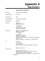
A
Specifications
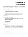
B
Error Messages
C
Accessing the Hardware
D
Using Assembly Language Subroutines
E
Hardware Installation Recommendations
F
ASCII Character Table
G
Bear BASIC Release History
H
UCP Onboard Hardware Support
I
Using Fuzzy Logic
Index
v
vi
Chapter 1
Introduction
1.1 Description of Features
1.2 Organization of This Manual
1.3 Notational Conventions
1-1
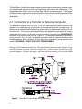
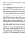
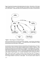
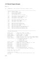
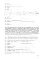
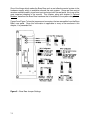
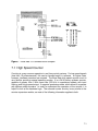
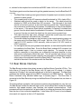
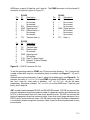
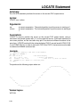
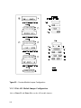
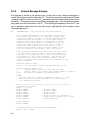
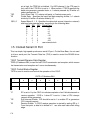
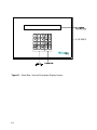
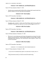
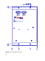
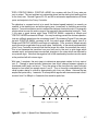
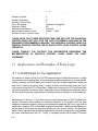
The Divelbiss Boss Bear is a unique programmable control system that integrates many
control functions into one easily used package. It starts as a compact, highly integrated
industrial computer system that is programmed using an extended, compiled BASIC. It
becomes an operations panel, containing a 2 line by 40 character display and a 20 key
entry pad; both are fully programmable to suit the user's requirements. It supports onboard
control hardware such as a high speed counter, analog inputs, a Real Time Clock, two
serial ports, nonvolatile memory, and EPROM storage of the user's programs. Three
expansion ports are available for adding optional modules, including analog outputs, analog
inputs, high speed counters, resolver inputs, high speed input/output, etc.
The Boss Bear can be interfaced to a Divelbiss Bear Bones programmable controller with a
single cable, allowing a true multi-processing system to be easily created; this forms an
inexpensive system that provides performance equal to much larger controllers.
Several Boss Bears can be linked together with a network to provide control over a larger
area or to return information to a central point. This network can then be linked to another
computer system, which can provide long term data storage and display, supervisory
control of the entire network, and perform Statistical Process Control.
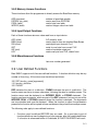
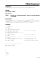
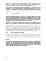
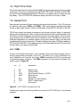
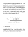
Figure 1 — Boss Bear system block diagram
1-2
1.1 Description of Features
A Boss Bear system consists of the Boss Bear, options added onboard the Boss Bear
itself, option modules plugged into the Boss Bear, and I/O expander modules connected to
the Boss Bear. By choosing the options carefully, an inexpensive system can be built with
only the hardware necessary to complete the task.
The minimal configuration of the Boss Bear contains the microprocessor circuitry with the
Bear BASIC compiler in PROM, 128K of RAM, an RS-232 serial port, EPROM
programming capability, and the Bear Bones interface. The RAM is used to hold the user's
program source code while it is being written, and to hold variables and data while the
user's program is executing. The serial port is used to interface with a terminal or personal
computer to allow entry and editing of programs. The onboard EPROM programmer allows
the user's program to be saved and loaded, either as source code or as executable object
code. The Bear Bones interface connects the Boss Bear to a Divelbiss Bear Bones
programmable controller to form a powerful multi-processing control system.
The Boss Bear may be purchased with a variety of options installed in the unit, such as a
front panel display and keypad, a high speed counter, analog input circuitry, a real time
clock, a second serial port, and nonvolatile memory.
The front panel display is a 2 line by 40 character display; this may be a liquid crystal
display (LCD), a backlit liquid crystal display, or a vacuum fluorescent display (VFD). The
keypad is a 4 row by 5 column tactile feel membrane keypad. These are both fully
programmable by the user.
The high speed counter is a 24 bit up/down counter with a built-in comparitor, providing a
high speed output when a specified count value is reached. This counter may be
programmed to support position control, rate metering, tachometer batch control, etc. It can
support multiple setpoints under software control.
The analog input circuitry contains an 8 channel, 10 bit, with 12 bit optional analog to digital
convertor (A/D). The values returned by the A/D can be displayed using the required
engineering units, used in a multiple setpoint control algorithm, and used as part of a PID
control loop, for example.
The Real Time Clock (RTC) maintains the current time and returns it as year, month, day,
hour, minute, second, day of week, and day of month. It is battery backed up, and so will
keep the correct time even when the Boss Bear is not powered.
The second serial port supports RS-232, RS-422, and RS-485. RS-232 is used to
communicate over short distances. RS-422 is used over longer distances and in
electrically noisy environments. RS-485 is used when several units need to communicate
over two wires, as in a network. The two onboard serial ports support 150, 300, 600, 1200,
2400, 4800, 9600, 19200, and 38400 baud.
1-3
1.2 Organization of This Manual
This manual is divided into 8 chapters, 5 appendices providing supplemental information,
and an index:
Chapter 1, "Introduction", provides an overview of the Boss Bear and a description of this
manual.
Chapter 2, "Getting Started With the Boss Bear", describes how to set up the unit, attach it
to a terminal, enter Bear BASIC programs, use the editor, and execute programs.
Chapter 3, "Overview of the Bear BASIC Compiler", describes the various elements of Bear
Basic and how they fit together.
Chapter 4, "Writing Control Applications in BASIC", is an elementary tutorial on
programming for real time control systems, with emphasis on using the features of Bear
BASIC.
Chapter 5, "Multitasking in Bear BASIC", explains the specifics of using the multitasking
features of Bear BASIC.
Chapter 6, "User Interface Support", describes how to use the onboard display and keypad,
and also discusses using a serial communications port with a terminal.
Chapter 7, "Onboard Hardware Support", describes the BASIC instructions that support the
hardware options available on the Boss Bear.
Chapter 8, "Bear BASIC Language Reference", is an alphabetical list of all direct
commands, statements, operators, and functions in Bear BASIC.
Chapter 9, "Optional Modules", describes the optional hardware modules that are available
for the Boss Bear.
Chapter 10, “Networking with the Boss Bear”, describes how to setup and use the Boss
Bear network.
Chapter 11, “Error Handling in Bear Basic”, deals with the onboard Basic compiler.
Appendix A, "Specifications", list of system hardware and software specifications.
Appendix B, "Error Messages", describes the Boss Bear error messages.
Appendix C, "Accessing the Hardware", is a technical description of the hardware available
onboard the Boss Bear.
Appendix D, "Using Assembly Language Subroutines", describes how to link assembly
language routines into a BASIC program.
1-4
Appendix E, "Hardware Installation Recommendations", provides guidelines for installing
the Boss Bear into the user's system.
Appendix F, “ASCII Character Table”, is the character table used in the Boss Bear.
Appendix G, “Bear Basic Release History”, is the version release history showing additions,
modifications and anomalies in the Boss Bear Basic.
Appendix H, “UCP Onboard Hardware Support”, is the description of the UCP hardware
differences from the Boss Bear.
Appendix I, “Using Fuzzy Logic”, is a brief description of fuzzy logic and how it is
implemented on the Boss Bear and UCP.
1.3 Notational Conventions
In this manual, the following conventions are used to distinguish elements of text:
BOLD
Denotes hardware labelling, commands, and literal portions of syntax
that must appear exactly as shown.
italic
Used for variables and placeholders that represent the type of text to
be entered by the user.
EXAMPLE
Used for example programs, sample command lines, and text
displayed by the Boss Bear.
SMALL CAPS
Used to show key sequences, such as CTRL-C, where the user holds
down the <Ctrl> key and presses the <C> key at the same time.
[]
Brackets are used to indicate optional elements of a command, such
as LOAD [program_num] where program_num is optional.
1-5
1-6
Chapter 2
Getting Started With the Boss Bear
2.1
2.2
2.3
2.4
2.5
2.6
2.7
Connecting to a Terminal or Personal Computer
Writing a Program in Bear BASIC
Bear BASIC Command Line Operation
Using the Command Line Editor
Loading and Saving Programs With a Personal Computer
Loading and Saving Programs With an EPROM
Automatically Executing a Program on Power Up
2-1
The Boss Bear is a relatively simple computer system to get up and running; normally, even
an inexperienced user can have the unit operating a short while after unpacking it. This
chapter describes how to set up the Boss Bear and use its basic features. The chapter
includes sample programs that may be entered to learn about the general functions of the
system; these programs may then be used as a starting point from which to develop
applications.
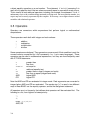
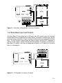
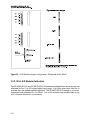
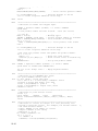
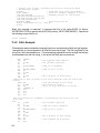
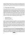
2.1 Connecting to a Terminal or Personal Computer
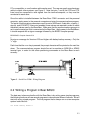
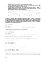
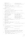
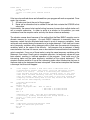
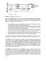
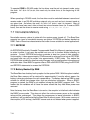
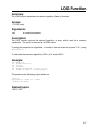
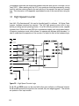
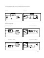
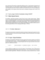
The Boss Bear requires a 10 volt AC or 12 volt DC power source in order to operate; see
appendix A to determine the current drain for the various Boss Bear configurations. A
transformer is available from Divelbiss that allows the unit to be powered from the 120 volt
AC power line. The unit has onboard rectification and regulation to generate the voltages
used inside the system. 10-12 volts is fed into the system using the 3 pin POWER INPUT
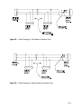
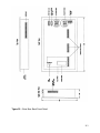
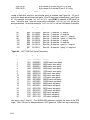
connector on the back of the unit; see Figure 2. It is extremely important to provide an
earth ground for the unit, both as a safety precaution and to minimize electrical noise
related problems; earth ground is the third prong on a standard 3 prong electrical wall
socket. WARNING: DO NOT USE AUTO TRANSFORMER.
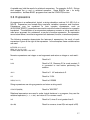
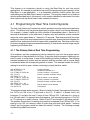
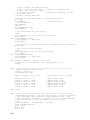
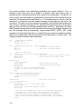
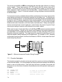
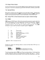
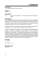
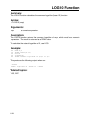
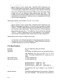
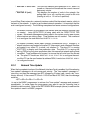
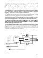
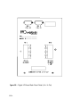
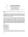
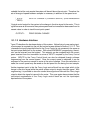
In order to program the Boss Bear, it must be attached to a terminal or a personal computer that is
running a serial communications program. This manual assumes that a personal computer is being
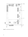
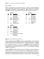
used; the operation of the unit is the same in either case. A cable connects the Boss Bear to the
personal computer; Divelbiss can supply a cable that will allow the unit to be used with an IBM
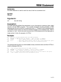
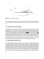
Figure 2 - Boss Bear Power Supply Wiring Schematic
2-2
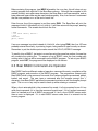
PC or compatible, or a null modem cable can be used. The user can easily manufacture a
cable to match other systems, see Figure 3. Note that pins 7 and 8 (the RTS and CTS
lines) must be connected to valid signals from the terminal/computer, or they must be
connected to each other.
Once the cable is installed between the Boss Bear COM1 connector and the personal
computer, apply power to the personal computer and enter the communications program.
The serial communications parameters must be set to 9600 baud, 8 data bits, no parity, 1
stop bit, and XON/XOFF flow control enabled; these values are required in order to match
the default values used by the Boss Bear. Make sure that the communications program is
set to use the serial port that is connected to the Boss Bear. Apply power to the Boss Bear;
it should respond with a signon message followed by the BASIC compiler prompt:
BEAR BASIC Compiler Version 2.01
>
No sign on message for Versions 2.03 and higher with battery backup memory. Only the
">" sign.
Each time that the ENTER key is pressed, the prompt character will be printed on the next line
down. The communications program should be set to emulate an ADM-3A or ADM-5
terminal type, in order for the cursor positioning commands on the Boss Bear to work
correctly.
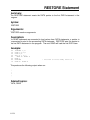
Figure 3 – Serial Port COM 1 Wiring Diagram
2.2 Writing a Program in Bear BASIC
The best way to become familiar with the Boss Bear is by writing some simple programs;
the following sections will use several programs to demonstrate different features. We will
start with a very simple program. The first program that is always run on a new computer
system looks like this:
100 PRINT "HELLO, WORLD!"
2-3
Before entering this program, type NEW followed by the ENTER key; this will clear out any
existing program that might be in the Boss Bear memory. Although the examples in this
manual primarily use upper case characters, the Boss Bear is not case-sensitive, and so
lower case and upper case may be used interchangeably. Also, from here on it is assumed
that the user presses ENTER at the end of each line.
Enter the one line of the program in and then enter RUN. The Boss Bear will print the
message COMPILED followed by HELLO, WORLD!. It will then return with the prompt, awaiting
further commands. The screen should look like this:
> NEW
> 100 PRINT "HELLO, WORLD!"
> RUN
COMPILED
HELLO, WORLD!
>
If an error message is printed instead of COMPILED, after typing RUN, then line 100 was
probably entered incorrectly; try entering it again, being careful to type it exactly as shown.
Remember to put the double quote marks around the HELLO, WORLD! message.
To modify a line of BASIC, just enter in a new line using the same line number; the new line
will overwrite the existing line. To remove a line of BASIC, enter the line number with
nothing after it; the line will be removed from the BASIC program. To look at your BASIC
program, enter LIST; the program will be displayed on the screen.
2.3 Bear BASIC Command Line Operation
Bear BASIC has three different modes of operation: command line entry, compilation of the
BASIC program, and execution of the BASIC program. The programmer interacts with
Bear BASIC while in the command line mode; this is where programs are entered, edited,
loaded, and saved. The user types a command after the compiler prompt (the '>'
character), then Bear BASIC performs the command and returns with the compiler prompt
again. The BACKSPACE key may be used to back up while entering a command.
When a line is entered while in the command line mode, it is first examined to see if it is a
valid direct command; if it is, then the command is performed. If it isn't a direct command,
then it is handled as a line of BASIC source code; if it isn't a line of BASIC source code,
then an error is displayed. If it is valid BASIC source code, then it is entered into the
current program.
2-4
2.4 Using the Command Line Editor
If it is necessary to change a line of the current BASIC program, the line can be retyped;
the new line will replace the existing line. This is fine for short lines, but for longer lines this
can cause a lot of extra typing. In order to minimize the effort required to modify a line of
the program, Bear BASIC includes a line editor as a direct command. The EDIT command
allows a single line of BASIC source code to be modified without retyping the entire line.
For EDIT to work properly, the line must be less than 80 characters long; it must fit on a
single line of the terminal. For the cursor positioning to work correctly in EDIT, the console
terminal type must be set to ADM-3A or ADM-5.
To use EDIT, type EDIT followed by the line number of the BASIC line to be modified; for
example, EDIT 120. The existing line will be displayed with the cursor at the first character in
the line number. The cursor may be moved left and right with the following key
combinations:
CTRL-S
CTRL-D
CTRL-A
CTRL-F
move the cursor left one character
move the cursor right one character
move the cursor to the beginning of the line
move the cursor to the end of the line
The editor can be toggled between insert and overwrite mode. In overwrite mode, any
character typed will replace the existing character at the current cursor position. In insert
mode, any character typed will be added at the current cursor position, causing the rest of
the line to be moved right one character position. When the editor is invoked, it starts out in
overwrite mode.
CTRL-V
toggles between overwrite and insert mode
To delete characters from the line, either BACKSPACE or CTRL-G can be used. The BACKSPACE
key deletes the character to the left of the current cursor position, causing the rest of the
line to be moved left one character position. CTRL-G, on the other hand, deletes the
character at the current cursor position, causing the rest of the line to the right to be moved
left one character position.
CTRL-G
deletes characters from line
When the desired changes have been made to the line, press ENTER to add the modified line
back into the program; the modified line will replace the existing line. Pressing ESCAPE or
any control key not listed above will abort the changes, leaving the existing line unchanged.
After leaving the editor, the compiler prompt will be displayed again.
2.5 Loading and Saving Programs With a Personal Computer
If the Boss Bear is being used with a personal computer as the console terminal, then it
may be desirable to transfer the current BASIC program to and from the computer's disk.
2-5
This allows the program to be edited on the personal computer, and to be printed out. The
exact method of transferring files depends upon the communications program that is being
used on the computer; it may be necessary to refer to the manual for that program to
ensure proper file transfer.
To transfer a program from the personal computer to the Boss Bear, enter NEW to clear
the current program out of memory, then enter DOWNLOAD. Execute the command in the
communications program to send a text (or ASCII) file, and type in the appropriate file
name. The file will be transferred to the Boss Bear. The file should not be echoed to the
screen; if it is being echoed, then it may indicate that a CTRL-Z is stored in the file. If any
syntax errors are encountered while sending the file, they will be displayed on the screen.
After the file has been transferred, the Boss Bear will probably respond with the compiler
prompt; if it doesn't, then type CTRL-Z, which turns off the DOWNLOAD mode. If two or more
lines were entered using the same line number, then the warning message Warning: duplicate
line numbers detected will be printed; this probably indicates an error in the BASIC source
code.
To transfer a program from the Boss Bear to the personal computer, type LIST but do not
press ENTER. Execute the command in the communications program to receive a text (or
ASCII) file, and type in an appropriate file name. After the program is ready to receive the
file, press ENTER to make the Boss Bear display the program; the program will capture it and
store it in the selected file on the personal computer. After the entire BASIC program has
been displayed, execute the command in the communications program to finish the
reception of the file.
2.6 Loading and Saving Programs With an EPROM
The Boss Bear includes an onboard EPROM programmer that is used to save the user's
programs. An EPROM is a device that can be written to electrically, but can only be erased
by exposing it to ultraviolet light; EPROM stands for Erasable Programmable Read Only
Memory. When an EPROM is erased, the entire contents of the EPROM are lost; there is
no way to only erase part of the EPROM. The same file can be stored multiple times,
allowing different versions to be saved while developing a program.
The programmer supports two sizes of EPROM: 32KB and 128 KB. KB stands for
KiloByte, which is 1024 bytes. The jumper JW3 (see Figure 6, page 7-2) must be set to
match the type of EPROM that is being used; failure to set the EPROM type correctly could
destroy the EPROM, along with its contents. The EPROM is mounted in a special carrier
for easier handling; the carrier ensures that the EPROM can't be installed backwards. The
switch SW1 must be set to PROG (program mode) before the EPROM can be written to.
After installing the EPROM and checking that the JW3 setting matches the EPROM type,
the EPROM is ready to use. The DIR command will display the contents of the EPROM
and the amount of unused space remaining. Two types of files can be stored on the
EPROM: source code and compiled code. The source code is the human readable BASIC
program; this should be stored so that it isn't lost. Compiled code is the executable code
generated by the Bear BASIC compiler; this is stored on an EPROM so that it can be
2-6
automatically executed on power up, or so that it can be CHAINed to from another
program. Each type of file is numbered sequentially on the EPROM, starting at 1.
After a BASIC program (the source code) has been typed in, it should be saved before
compiling it and attempting to execute it; this is so that the program won't be lost if the Boss
Bear crashes when the program is run. When entering a long program, it is also advisable
to save the program periodically so that the entire program isn't lost in the event of a power
failure. To save the source code to EPROM, type SAVE progname, where progname is
the name of the program. The program name will be stored as the file name on the
EPROM; if progname isn't entered, then it will default to all spaces.
After a program has been successfully compiled (ie. no syntax errors were encountered by
the compiler), then the compiled code can be saved to the EPROM, by typing SAVE CODE
progname, where progname is the name of the program. The program name will be stored
as the file name on the EPROM; if progname isn't entered, then it will default to all spaces.
2.7 Automatically Executing a Program on Power Up
When the user's program is operational and the Boss Bear is to be installed, it will probably
be necessary for the Boss Bear to automatically execute the program when it is turned on.
If SW1 is set to RUN (run mode), then the Boss Bear will load the last compiled code file
from the EPROM and execute it. Since the Boss Bear executes the last compiled code file
from the EPROM, the latest revision of a program will always be executed. If SW1 is set to
PROG (program mode), then the Boss Bear will respond with the compiler prompt when it
is turned on. Preprogrammed Eprom cannot be used with newer versions of firmware
without downloading and recompiling (erase Eprom and reprogram).
2-7
2-8
Chapter 3
Overview of the Bear BASIC Compiler
3.1
3.2
3.3
3.4
3.5
3.6
3.7
3.8
3.9
Direct Commands
Organization of a Bear BASIC Program
Numeric Constants
Variables
Operators
Expressions
Statements
Functions
User Defined Functions
3-1
The Boss Bear software consists of two parts: the command line interface and the Bear
BASIC compiler. The command line interface executes direct commands as they are typed
in; it enters the BASIC source code, loads and saves programs, executes programs, and
starts the compiler. Section 3.1 describes the direct commands that are available. The
compiler converts BASIC source code into executable compiled code; it's input is the
current BASIC program in memory. Sections 3.2 through 3.9 describe the BASIC compiler,
the syntax of Bear BASIC, and the statements and functions that Bear BASIC supports.
The Bear BASIC commands, statements, and functions are described individually in
chapter 8.
3.1 Direct Commands
Direct commands are used while programming the Boss Bear, and entered at the compiler
prompt. They can be grouped into three categories: file commands, compiler commands,
and miscellaneous commands.
3.1.1 File Commands
DIR
DOWNLOAD
LOAD [filenum] or
EPROM LOAD [filenum]
SAVE [CODE] [fname] or
EPROM SAVE [CODE] [fname]
display a listing of files on the EPROM
disable echo while loading a program
load a program from the EPROM
load a program from the EPROM
save source or compiled code to the EPROM
save source or compiled code to the EPROM
3.1.2 Compiler Commands
C
COMPILE or C
ERROR
G
GO or G
NOERR
R
RUN or R
STAT
abbreviation for COMPILE
compile the BASIC program
enable error checking in compiled BASIC
abbreviation for GO
start the compiled program executing
disable error checking in compiled BASIC
abbreviation for RUN
compile and execute the current BASIC program
display memory usage and compiler version
3.1.3 Miscellaneous Commands
BYE
CLEARMEMORY
CLS
E linenum
EDIT linenum or E
HELP
L
LIST [linenum] [,linenum]
3-2
reset the Boss Bear
write 0's into all memory locations
erase the console display
abbreviation for EDIT
enter the line editor to alter linenum
display help text
list the entire program
list all or part of the program
LFDELAY
NEW
SETOPTION DAC
delay at the end of each line displayed
clear out the current BASIC program
set DAC initialization values
3.2 Organization of a Bear BASIC Program
The Bear BASIC language has a structured syntax that requires that particular elements of
a program be placed in a specific order. Failure to follow this syntax could result in syntax
errors, or, worse yet, an inoperable program.
3.2.1 Program Lines
A Bear BASIC program consists of a series of program lines, sometimes referred to as
lines of code, or source lines. Each program line has a line number followed by one or
more statements. The line number is an integer between 1 and 32767. If there is more
than one statement in a program line, then each statement is separated by a colon (':').
The following are valid Bear BASIC program lines:
100 X=4
35 print "Hi there"
32000 J=K*4 + 3: IF J>0 Then GOSUB 2000:j=0
The following are invalid program lines:
43000 PRINT X
Line number is too large
100 X=4 J=X
No colon between statements
Bear BASIC does not require line numbers; if a line is entered without a line number, it will
add 2 to the previous line number and assign that number to the new line. If used carefully,
this can make the BASIC source code much more readable when it is viewed on a personal
computer. BASIC stores lines in a tokenized format, where special codes are stored
instead of the actual statement, in order to save space. A side effect of this is that the
program will look different when it is LISTed than when it was entered. An example will
demonstrate this; if the following is typed:
100
130
integer j,sum
sum=0
for j=1 to 100
sum=sum+j
next j
print "The sum is "; sum
' Initialize the sum
' Add up the numbers
' Display the result
3-3
when this program is LISTed, the following is displayed:
100
102
104
106
130
132
INTEGER J,SUM
SUM=0: ' Initialize the sum
FOR J=1 TO 100
SUM=SUM + J: ' Add up the numbers
NEXT J
PRINT "The sum is ";SUM: ' Display the result
Notice that line numbers were added to the lines that didn't have them. Also, the only
lowercase letters that remain are in text strings and comments. Bear BASIC is not case
sensitive, so code can be entered in upper or lower case, but it is always stored in upper
case.
3.2.2 Variable Declarations
Unlike many BASIC systems, all Bear BASIC variables must be explicitly declared. All
variable declarations (ie. INTEGER, REAL, and STRING statements) must be at the
beginning of the program. In order to create efficient code, the compiler needs to know
how many variables there are before it generates any machine code. Bear BASIC is limited
to 128 variable names in a program. No distinction is drawn between variables by mode.
This means that the variable A2 is the same variable as A2$. If the variable is declared as
both integer and string (both INTEGER A2 and STRING A2$ statements exist), a compilation
error will result. Similarly, variable A is the same as dimensioned variable A(n). Bear
BASIC supports a maximum of two dimensions for real and integer arrays; it supports
single dimension string arrays.
3.2.3 DATA and READ Statements
All DATA statements must be located before the first READ statement in the program.
DATA statements can be interspersed with other executable statements, but no DATA
statement can follow a READ statement.
3.2.4 Placement of Tasks
In a multitasking program, the beginning of each task is identified with a TASK statement.
The TASK statements must be in ascending numerical order starting with TASK 1. When a
task is run, it begins execution with the statement following the TASK statement. The code
located before the TASK 1 statement actually belongs to task 0; task 0 is present in every
Bear BASIC program. The placement of tasks and subroutines can be critical. In general,
the safest method is to not call subroutines that are located in another task. See Chapter 5
for further discussion of multitasking.
3.3 Numeric Constants
Constants are formed by combining decimal digits with an optional decimal point. Whenever a
decimal point is included in a constant, the compiler assumes this constant is a real number. If the
constant is expressed without a decimal point, the compiler assumes that the value is an integer.
This has significance when combining real and integer values within an expression. Even though
3-4
Bear Basic is smart enough to convert constants between integer and real as required, programs
will run more efficiently if modes are not mixed. Bear Basic provides a facility for using
hexadecimal constants. Hexadecimal constants are specified with a leading dollar sign. $1AB
represents the hexadecimal constant 1AB.
3.4 Variables
Bear BASIC variables are formed by a letter followed by up to six letters or digits. For
example, A is a legal variable, as well as A0, A1, HI92, and JUMP. However, 9AB is not a
legal variable, nor is A1234567899. String variables are formed the same way, but are
followed by a dollar sign. HIYA$, A1$, A9$ are all legal string variables. A maximum of
128 different variables may exist in any given program. These variables may be in any
form within the rules given above. Note that integer or real variables may not have the
same name as string variables. For example, the variable A may not be used in the same
program that uses the variable A$. Bear BASIC will try to use A and A$ as the same
variable, and a string variable error will result. Similarly, a dimensioned variable must not
have the same name as an undimensioned variable (for example, you cannot use B and
B(n) in the same program).
All variables must be declared at the beginning of the program before any executable code
is encountered. In practice, this means that the variable declaration statements (INTEGER,
REAL, and STRING) should be the first statements in the program. If undeclared variables
are found during the compilation, the compiler will display an error message. For strings,
the string length is specified in the STRING statement (for example, B$(80)). If no string
length is specified, a string length of 20 will be assigned. The maximum allowable string
length is 127.
String arrays are defined by specifying the length of each element, followed by the number
of elements in the array. STRING A$(10,20) specifies 20 strings, each of length 10. Any
element can be accessed just like a singly dimensioned array. A$(3)="123" assigns a value
to the third element of the string array.
Subscripted variables are specified within the INTEGER and REAL statements. Note that
subscripted variables start with the zero dimension, and extend to the maximum dimension
specified. Therefore, the statement INTEGER A(10) defines a variable with eleven
members, A(0) through A(10).
Integer variables are stored using a sixteen bit two's complement representation. An
integer value can range from +32,767 to -32,768. Positive values which exceed 32,767 will
appear as negative numbers. Real values are four byte (32 bit) IEEE compatible single
precision real numbers. This means that approximately 6.5 digits of precision are
maintained for real numbers (ie. numbers between ±3.4028235x1038). Many BASIC
interpreters and compilers use BCD mathematics or 64 bit representations resulting in high
accuracy numbers that require lots of memory. Bear BASIC does not support either of
these in the interest of maximizing speed. The user must be aware that a real number may
not be exactly the number anticipated. For example, since real numbers are constructed
by using powers of 2, the value 0.1 cannot be exactly represented. It can be represented
very closely (within 2-23), but it will not be exact. Therefore, it is very dangerous to perform
3-5
a direct equality operation on a real number. The statement IF A=0.123 (assuming A is
real) will only pass the test if the two values are exactly equal, a case which rarely occurs.
This is true for all real relational operators, including, for example, the statement IF A>B, if
values very close to the condition being measured are being used. Be aware that the number you
expect may not be exactly represented by the compiler. If necessary, use a slight tolerance around
variables with relational operators.
3.5 Operators
Operators are connectors within expressions that perform logical or mathematical
computations.
These operators work both with integer and real numbers:
+
*
/
addition
subtraction
multiplication
division
Some operators are relational. They generate a nonzero result if their condition is met; the
nonzero value is unspecified (ie. it isn't necessarily 1 or -1, as in many languages). These
operators may be used in mathematical expressions, but they are more frequently used
with IF/THEN statements:
>
<
<> or ><
=
>=
<=
AND
OR
greater than
less than
not equal to
relational equality test
greater than or equal (integers and reals)
less than or equal (integers and reals)
logical AND
logical OR
Note that AND and OR are evaluated in integer mode. Real arguments are converted to
integer before AND and OR are evaluated. The equals sign ('=') is used in two different
ways in Bear BASIC: as the equality operator, and as the assignment statement.
All operators are in a hierarchy that defines what operators will be evaluated first. The
following is a list, from highest to lowest priority:
*, /
+,unary -, >, <, <>, ><
AND, OR
3-6
A variable may hold the result of a relational comparison. For example, A=R>0. Strings
don't support the >= and <= relational operators. Some BASICs use + for string
concatenation, but Bear BASIC programs must use the CONCAT$ function.
3.6 Expressions
An expression is a mathematical, logical, or string calculation, such as 2+3, A/B, A=4, or
N$>C$. Expressions are formed using constants, variables, operators, and functions.
Expressions may be combined to form complex expressions, such as
(A+B)/SIN(A*SQR(C)); parenthesis are used to control the order of evaluation in a complex
expression. The evaluation of an expression produces a numeric or string result that is
used as an argument for a statement, or as part of another expression. An expression
cannot stand alone; it must be an argument to a statement, function, or another expression.
The following examples demonstrate the features of expressions; the result of each
expression is given to the right of the expression. In the examples, these variable values
are used:
INTEGER J,K: J=4: K=7
REAL X,Y: X=2.3: Y=5.8
STRING A$,B$: A$="ABC": B$="DEF"
Numeric expressions use integer or real arguments and return an integer or real result:
2+3
Result is 5
2.0+3
Result is 5.0. Because 2.0 is a real constant, 3
is converted to real before performing the
addition.
J/K+2
Result is 2. J/K evaluates to 0.
X*Y
Result is 13.34.
SQR(X*X+Y*Y)
Result is 6.23969
String expressions use string arguments and return a string result:
CONCAT$(A$,B$)
Result is "ABCDEF"
Relational expressions are used to make logical decisions in a program; they use the
relational operators (>, <, =, etc.) and return a 0 or nonzero result:
3>5
Result is 0, since 3 is not greater than 5.
A$<>B$
Result is nonzero, since A$ is not equal to B$.
3-7
Bear BASIC is unlike many BASIC dialects in that it forces the user to declare the mode of
each variable, thereby optimizing the compiler's speed. With all variables predeclared, the
compiler is not forced to evaluate all expressions in floating point at run time (which is a
very slow procedure), and then convert to integer as the need arises. Instead, the
algorithms used in Bear BASIC attempt to evaluate all expressions in the output mode (the
mode of the variable to which the expression is being assigned). To make it easier to write
programs, Bear BASIC provides automatic mixed mode expression evaluation. This means
that an expression may consist of a combination of real and integer values. Bear Basic will
automatically convert the components of the expression to the proper mode before
evaluating it, and will convert the result to the mode of the variable to which the expression
is being assigned. This is very convenient for programmers; however, there are some
important implications arising from it.
Whenever an expression is to be assigned to a real variable, then every component of that
expression is evaluated in real mode. Components of the expression which are integer (for
example, integer variables), are automatically converted to real before any arithmetic is
performed. This conversion takes place entirely within temporary values in the compiler;
the integer values themselves are not changed. Whenever a constant is specified with no
decimal point, the compiler assumes that it is an integer value. Any constant designated
with a decimal point will be assumed to be real. Since the process of converting an integer
to a real is relatively slow, faster code will result with real operations when all real operands
are specified.
Expressions are defined in terms of parentheses. Whenever an expression in parentheses
is encountered, this is treated as a new expression, although it may be part of a larger
expression. This has significance when expressions are being evaluated which will be
assigned to integer arguments. When the compiler encounters a new expression (one with
parenthesis), it attempts to evaluate that expression in the mode of the variable to which it
will be assigned. In the case of a real operator this is not important, since all values are
converted to real before any operation takes place. With integer variables, however, if any
component of an expression is real, the rest of that expression will be converted to real
before the operation takes place. A few examples will make this clear.
100 INTEGER A
110 A=(1/2)*2
In this case, the expression will evaluate to the value zero. All operations specified are
integer. Integer operations take place by truncating the result, so 1 divided by 2 evaluates
to 0.
100 INTEGER A
110 A=(1.0/2)*2
This expression also evaluates to zero, but for a different reason. The inner 1.0/2
evaluates to .5, but after the value is calculated, the compiler attempts to convert this back
to integer to be in the proper mode for variable A. The integer version of 0.5 is 0.
100 REAL A
110 A=(1.0/2)*2.0
3-8
In this case, the expression will evaluate to 1. Each of the operations is real, so all
operations take place in real mode.
100
110
120
130
140
INTEGER MOTOR
REAL SPEED
SPEED=750.0
MOTOR=(SPEED/100.0)*1023/10
DAC 1,MOTOR
' DAC value to send to motor controller
' Speed setpoint for motor
' Set to 750 RPM
' Convert RPM to DAC value
This example illustrates the problem that can occur with real/integer conversions in
expressions. In the example, it is assumed that DAC channel 1 is attached to a motor
controller which accepts a 0 to 10 VDC input; each 1 VDC corresponds to 100 RPM (ie 3.4
VDC is 340 RPM). Line 130 converts the speed, given in RPMs, to the DAC value
necessary to set the motor controller speed. Since the DAC statement works with integer
values, it seems reasonable that MOTOR should be an integer. SPEED is a real, so we
want the calculation to be handled using real numbers (result=767.25); the result should be
truncated and stored in MOTOR (767). Unfortunately, when Bear BASIC evaluates the
parenthesis, it converts the result at that point (7.50) to an integer (7), and then evaluates
the rest of the expression in integer mode. The integer multiplication of 7*1023 causes a
final result of 716. This is a relatively small error, but if the numbers that were being
multiplied resulted in a value greater than 32767, then the integer overflow would cause the
actual result to be quite far off.
By changing MOTOR to a real, the calculation in line 130 is performed as intended,
providing a result of 767.25 to be stored in MOTOR. When the DAC statement is executed
in line 140, MOTOR is truncated to 767, which is the expected result.
If MOTOR is left as an integer, and the parenthesis in line 130 are removed, then the
correct result is also obtained. In this case, the entire calculation is performed in real
mode, and then the result (767.25) is truncated and stored in MOTOR.
3.7 Statements
Statements describe the actions to be taken by the Bear BASIC program. Multiple
statements can be placed in a line, separated by colons (':'). Statements can be grouped
into seven categories: program flow, data storage, memory access, I/O, function definition,
multitasking, and miscellaneous.
3.7.1 Program Flow Statements
Bear BASIC normally executes statements in linear order, as they are stored in the
program. The following statements modify the program flow to allow code to be executed
multiple times, to allow code to be shared, and to allow the program to make decisions.
CALL laddr [,arg...]
CHAIN filenum or "fname"
CHAIN "fname"
call an assembly language subroutine
load and run another program from EPROM
load and run another program from EPROM
3-9
FOR num=expr TO expr [STEP expr]
GOSUB linenum
GOTO linenum
IF expr THEN
NEXT
ON ERROR linenum
ON expr, GOSUB linenum [,linenum...]
ON expr, GOTO linenum [,linenum...]
RETURN
STOP
SYSTEM laddr,regarray
beginning of a program loop; see NEXT
call a subroutine; see RETURN
jump to a line number
conditional execution of rest of line
end of a program loop; see FOR
GOTO linenum if an error occurs
call subroutine based on value of expr
jump to linenum based on value of expr
continue at line following GOSUB
halt execution of program
call an assembly language subroutine
3.7.2 Data Storage Statements
These statements are used to declare the variables that are used in the program, and to
embed data values in the program.
DATA arg [,arg...]
INTEGER varname [,varname...]
READ arg [,arg...]
REAL varname [,varname...]
RESTORE
STRING varname [,varname...]
store data for READ to access
declare signed integer variables
read values from DATA statements
declare floating-point variables
reset READ pointer to first DATA statement
declare text string variables
3.7.3 Memory Access Statements
These statements allow the programmer to directly access the Boss Bear memory.
CODE int [,int...]
DEFMAP int
EEPOKE ee_addr,int
POKE laddr,byte
WPOKE laddr,int
store assembly language code in program
set memory map for POKE, PEEK, etc.
store a word in EEPROM
store byte at laddr
store integer value at laddr
3.7.4 Input/Output Statements
Control applications depend upon input and output with the real world, and the Boss Bear
supports a wide variety of I/O devices, so this is the largest group of Bear BASIC
statements.
BBOUT chan,bin_val
send a data bit to an attached Bear Bones
CLS
erase the current FILE display device
CNTRMODE chan,int
set operating mode for counter
DAC chan,int
set D/A output level
DOUT chan,bin_val
control digital output channel
ERASE
erase the current FILE display device
FILE int
set current file I/O device
FINPUT fmt_str,arg
formatted INPUT from current FILE
FPRINT fmt_str,arg [,arg...]
formatted PRINT to current FILE
3-10
GETDATE month,day,year,wday
GETIME hour,minute,second
GOTOXY xpos,ypos
INPUT arg [,arg...]
INPUT$ arg [,arg...]
INTERRUPT device,chan,task
LOCATE row,col
NETMSG
NETWORK 0,unit,int,int,int,st
NETWORK 1,type,reg,int,unit,reg,st
NETWORK 2,type,reg,int,unit,reg,st
NETWORK 3,type,reg,expr,st
NETWORK 4,type,reg,varname,st
OUT port,byte
PRINT arg [,arg...]
RDCNTR chan,int,varname
SETDATE month,day,year,wday
SETIME hour,minute,second
WRCNTR chan,int,expr
get current date from real time clock
get current time from real time clock
set cursor position for current FILE device
wait for user input from current FILE
allow commas in user input
attach a task to a hardware interrupt source
set cursor position for current FILE device
send/receive network messages
initialize Boss Bear network handler
send registers to another Boss Bear
read registers from another Boss Bear
set the value of a network register
read the value of a network register
send byte to hardware output port
send output to current FILE device
read counter value into varname
set current date of real time clock
set current time of real time clock
write to counter register(s)
3.7.5 Function Definition Statements
Bear BASIC allows the programmer to extend the language by adding functions. See
section 3.9 for a complete description.
DEF funcname [,arg...]
FNEND
mark beginning of a user defined function
mark end of a user defined function
3.7.6 Multitasking Statements
These statements support the multitasking ability of Bear BASIC, allowing the programmer
to control which tasks are running and how often they are running.
CANCEL task
EXIT
JVECTOR laddr,task
PRIORITY int
RUN task [,int]
TASK task
VECTOR laddr,task
WAIT int
halt the rescheduling of a task
abort execution of current task
store a jump instr. for an interrupt vector
set priority of current task
begin task execution; set resched. interval
mark the beginning of a task area
store task number to an interrupt vector
suspend task execution for int tics
3.7.7 Miscellaneous Statements
DEBUG
INTOFF
INTON
RANDOMIZE
halt compile process to display variables
disable all interrupt processing
enable all interrupt processing
re-seed the random number generator
3-11
REM [string]
TRACEON
TRACEOFF
comment text
enable line number trace on current FILE
disable line number trace on current FILE
3.8 Functions
A function is called by referencing it in an expression. A function returns an integer, real, or
string result. Functions can be grouped into five categories: math, string, memory access,
I/O, and miscellaneous.
3.8.1 Math Functions
These include trigonometric, logarithmic, and bitwise logical functions.
ACOS (expr)
ASIN (expr)
ATAN (expr)
BAND (expr,expr)
BOR (expr,expr)
BXOR (expr,expr)
COS (expr)
EXP (expr)
LOG (expr)
LOG10 (expr)
RND
SIN (expr)
SQR (expr)
TAN (expr)
arccosine of expr
arcsine of expr
arctangent of expr
bitwise logical AND of expr's
bitwise logical OR of expr's
bitwise logical XOR of expr's
cosine of expr
exponential function e**expr
natural logarithm (base e) of expr
common logarithm (base 10) of expr
generate a pseudo-random number
sine of expr
square root of expr
tangent of expr
3.8.2 String Functions
These are used to work with strings and convert between strings and numbers.
ASC (strexpr)
CHR$ (expr)
CONCAT$ (strexpr, strexpr)
CVI (strexpr)
CVS (strexpr)
LEN (strexpr)
MID$ (strexpr,expr,expr)
MKI$ (expr)
MKS$ (expr)
STR$ (expr)
VAL (strexpr)
3-12
ASCII equivalent of first char. in strexpr
one char. equivalent of expr
appends second string after first
converts binary string to integer
converts binary string to real
length of strexpr
substring of strexpr
converts an integer to a binary string
converts a real to a binary string
converts a number to a string
converts a string to a number
3.8.3 Memory Access Functions
These functions allow the programmer to directly access the Boss Bear memory.
ADR (varname)
EEPEEK (ee_addr)
PEEK (laddr)
WPEEK (laddr)
address of specified variable
read a word from EEPROM
read a byte from laddr
read an integer value from laddr
3.8.4 Input/Output Functions
Each of these functions returns a value read from an input device.
ADC (chan)
BBIN (chan)
DIN (chan)
GET
INP (port)
KEY
A/D value for chan
read a data bit from an attached Bear Bones
read digital input channel; 0 or 1
waits for one byte from current FILE
reads a hardware output port
reads one byte from FILE, doesn't wait
3.8.5 Miscellaneous Functions
ERR
last error number generated
3.9 User Defined Functions
Bear BASIC supports multi-line user defined functions. A function definition may be any
number of lines long. All functions must be defined as follows:
100 DEF function_name [arguments]
110 function_definition
120 FNEND
DEF indicates the start of a definition. FNEND indicates the end of a definition. The
function name can be up to seven characters, following the rules for variable names. The
function name must be declared in an INTEGER, REAL, or STRING statement. The
function can have arguments, which are part of the DEF statement, but are not part of the
INTEGER, REAL, or STRING statement where the function is declared. The arguments
are true variables and must be declared. When the function is called, the parameters
passed to the function will be copied to these variables so they should have unique names.
The following rules apply to user defined functions:
•
Functions must be defined BEFORE they are used. It's a good idea to put all
function definitions near the beginning of your program, after the variable definitions.
If a function is referenced before it is declared, a FUNCTION ERROR will result.
3-13
•
•
•
•
•
•
A maximum of 64 functions can be declared in one program.
Function definitions cannot be nested. A FUNCTION ERROR will result if a DEF
statement is found inside of a function definition.
Function names must be unique. Do not use other variable names or names of
Bear BASIC statements or functions (even a function name very close to a Bear
BASIC reserved word may not be acceptable).
Arrays cannot be used as arguments to functions. Only simple strings, reals, or
integers are legal.
Do not attempt to perform console inputs or outputs inside of a function if it will be
used in a multitasking program. Your program may hang up since Bear Basic
blocks console access during some multitasking operations.
Functions are not recursive. A function cannot call itself, either directly or indirectly.
The result of a function can be assigned to the function name. To do this, in the function
definition use an assignment statement to place the desired value in the function's name
(ie. reference the function name like it was a variable name). In the assignment statement,
do not specify the function's arguments on the left hand side of the "=" sign. For example,
the following function returns the value 1:
100
110
120
130
140
INTEGER FN1
DEF FN1
FN1=1
FNEND
PRINT FN1
' The value 1 will be printed.
The following function returns the sum of its arguments:
100
110
120
130
140
INTEGER FN1,A,B,C
DEF FN1(A,B,C)
FN1=A+B+C
FNEND
PRINT FN1(1,2,3)
' The value 6 will be printed.
Note that in line 120 the function is referred to without its arguments.
Here's another example. This function returns the left N characters of a string:
100
110
120
130
140
150
STRING LEFT$(127), A$(127)
INTEGER N
DEF LEFT$(A$,N)
LEFT$=MID$(A$,1,N)
FNEND
PRINT LEFT$("ABCDEF",3)
' This prints "ABC"
One function can reference another. For example:
100
110
120
130
INTEGER FNA, FNB
DEF FNB : FNB=1 : FNEND
DEF FNA : FNA=FNB : FNEND
PRINT FNA
' This
prints "1"
If functions that are using strings call each other, the STRING SPACE EXCEEDED error can
result if too many functions have partial string results stored in internal temporary storage.
3-14
If the message appears, you've called too many functions that need intermediate string
storage. Simplify your code somewhat.
3-15
3-16
Chapter 4
Writing Control Applications in BASIC
4.1 Programming for Real Time Control Systems
4.2 Project Specification
4.3 Real Time Programming Example
4-1
This chapter is an introductory tutorial on using the Boss Bear for real time control
applications. An example is provided to help clarify the programming and operation of the
Boss Bear in a real application; it is a moderately complex control system that uses
multitasking and the Bear Direct network interface. The program makes use of features
which are described later in this manual, so the reader is advised to make use of the index
when topics come up which haven't been covered previously.
4.1 Programming for Real Time Control Systems
The term 'real time control' implies that certain operations must be performed at particular
times. This differs from the general application program, which is not timing dependent.
For example, it doesn't matter too much whether a spreadsheet takes 1 second or 10
seconds to recalculate; on the other hand, it matters very much whether a motor controller
ramps the motor speed down in 1 second or 10 seconds. Real time events fall into three
categories: events that must happen before a specified time, events that must happen at a
specified time, and events that must happen after a specified time. Real time control often
involves managing multiple processes concurrently; in other words, several things may be
happening at the same time.
4.1.1 The Primary Rule of Real Time Programming
At its simplest, real time programming can be reduced to one rule: the program cannot
disregard any of the processes for too long. At any time that the program is waiting for an
event to occur in one process, it must still be handling the other processes. The following
example implements a system with two switches and two counters, with a counter being
incremented when the corresponding switch is closed. This example breaks the rule by
waiting for a switch to open, without continuing to check the other switch.
100
105
110
120
125
130
140
150
155
160
170
INTEGER C1, C2
C1=0: C2=0
IF DIN(1)=0 THEN 140
C1=C1+1
PRINT "C1 = "; C1
IF DIN(1)=1 THEN 130
IF DIN(2)=0 THEN 170
C2=C2+1
PRINT "C2 = "; C2
IF DIN(2)=1 THEN 160
GOTO 110
' Counter variables
' Initialize the counters to 0
' Continue if switch 1 not pressed
' Switch 1 pressed, increment counter
' Wait for switch 1 to be released
' Continue if switch 2 not pressed
' Switch 2 pressed, increment counter
' Wait for switch 2 to be released
' Loop forever
This program almost works correctly. When no switch is closed, the program will loop from
line 110 to line 140 to line 170 and back to line 110. If switch 1 is closed, then it will
increment C1 and print the new C1 value in lines 120 and 125. It will then sit in a loop in
line 130 until switch 1 is opened; when this happens, it will resume looping from 110 to 140
to 170, looking for a switch closure. Switch 2 and C2 are handled in the same manner.
The problem occurs when it is waiting for a switch to be opened (lines 130 and 160). If it is
looping in line 130, for instance, switch 2 could close and open while switch 1 remains
closed, and the program would not detect the switch 2 closure. The following example
handles this problem and counts
4-2
the two switches correctly.
100
110
120
130
140
150
160
170
180
190
200
210
300
310
320
330
340
350
INTEGER C(1)
' Counters
INTEGER S(1)
' Switch states
INTEGER J,K
C(0)=0: C(1)=0
' Initialize the counters to 0
FOR J=0 TO 1
' Loop for both switches
GOSUB 300
' Check for switch closure
IF K=0 THEN 190
' Jump if no closure
C(J)=C(J)+1
' Increment counter
PRINT "C"; J;" = "; C(J)
' Print counter
NEXT J
GOTO 140
' Loop forever
'
' Subroutine to check for switch 'J' closure. If the switch was previously
' open and is closed now, then return a 1; otherwise, return a 0.
K=DIN(J+1)
IF K=1 AND S(J)=0 THEN S(J)=K: RETURN
IF K=0 AND S(J)=1 THEN S(J)=K
K=0: RETURN
This program is designed much better than the previous one; it is easily modified to handle
more switches, by changing the size of the arrays 'C' and 'S' and the loop size in line 140.
It constantly checks the state of both switches, incrementing the count when it detects that
a switch has closed. Since it continues checking the state of both switches at all times, it
won't miss a switch closure. The PRINT statement in line 180 will take about 5
milliseconds to complete (5 characters at 9600 baud). This means that it could miss a
switch closure that lasts less than 5 msec; normally, a switch closure this short would be
interpreted as a glitch, anyway, but it is still worth noting. In real time programming, any
time delay must be examined to see how it affects the operation of the system.
The first program could be made to work correctly by using the multitasking feature of Bear
BASIC. In the second example, extra code was written to allow the processor to perform
two functions at once; actually it switched between them quickly to give the appearance of
concurrent operation. This is precisely what the Bear BASIC context switcher does, so the
program could be simpler if it took advantage of the context switcher. Two tasks would be
written, with each one devoted to monitoring a switch. The following example
demonstrates this technique; note that the two tasks are very similar to the two loops from
the first example. Because each task gets 50 percent of the processor time, by executing
every other tick, a switch state that is shorter than 10 msec (one tick) may be missed. For
example, if the program is executing in line 210, and switch 2 toggles low and then high
again 5 msec later, then when task 2 executes it will see input 2 high as if nothing had
happened.
100
110
120
200
210
220
230
240
250
300
305
310
320
330
340
INTEGER C1, C2
C1=0: C2=0
RUN 1
' Handle first switch
IF DIN(1)=0 THEN 210
C1=C1+1
PRINT "C1 = "; C1
IF DIN(1)=1 THEN 240
GOTO 210
' Handle second switch
TASK 1
IF DIN(2)=0 THEN 310
C2=C2+1
PRINT "C2 = "; C2
IF DIN(2)=1 THEN 340
' Counter variables
' Initialize the counters to 0
' Wait for switch 1 to be pressed
' Switch 1 pressed, increment counter
' Wait for switch 1 to be released
' Loop forever
' Wait for switch 2 to be pressed
' Switch 2 pressed, increment counter
' Wait for switch 2 to be released
4-3
350
GOTO 310
' Loop forever
4.1.2 Managing Timing in a Control System
Obviously, one of the most important functions of a real time program is to ensure that
control operations happen at the proper time. Bear BASIC provides three methods for
handling real time scheduling of operations: the real time clock, the WAIT statement, and
the hardware timer. Each of these covers different areas of real time scheduling.
With a resolution of one second, the real time clock is only useful for handling relatively
long time periods. This makes it ideal for keeping track of down-time, run-time, shift totals,
daily totals, and other long term production statistics. Care must be used when
programming with a real time clock, because of the possibility of wrap-around at the end of
the minute, end of the hour, and end of the day. Also, the programmer must be aware of
the size of numbers that result when working with time of day values; for example, there
are 86400 seconds in a day, which means that an integer won't hold an entire day in
seconds. The following example shows how to handle the real time clock for long time
periods:
100
102
' Example to demonstrate using the real time clock to measure
' long time intervals.
110
120
INTEGER HA, MA, SA
INTEGER J, K, FLAG1, END1
130
FLAG1=0
190
192
200
210
220
230
240
250
260
270
' When input 1 turns on, turn on output 1. When input 1 turns off,
' wait for 140 seconds, then turn off output 1.
J=DIN(1)
IF J=0 AND FLAG1=0 THEN 200
' Input off, keep waiting
IF J=1 AND FLAG1=1 THEN 200
' Input on, keep waiting
IF J=0 THEN 300
' Jump if input just turned off
' Input just turned on, so turn on output
DOUT 1,1
FLAG1=1
GOTO 200
300
310
320
330
340
350
360
370
380
' Input just turned off, so wait for 140 seconds, then turn off output 1.
GETIME HA,MA,SA
' Get current time
END1=MA*60+SA+140
' Calculate end time (cur.time+140)
IF END1>3599 THEN END1=END1-3600
' Convert to 0-3599 range
GETIME HA,MA,SA
IF MA*60+SA <> END1 THEN 340
' Wait for 140 seconds to pass
DOUT 1,0
FLAG1=0
GOTO 200
In order to execute a 140 second delay, the program reads the real time clock in line 310.
It converts the minutes (0-59) and seconds (0-59) to just seconds (0-3599), and adds in the
140 second delay time. This could result in a number larger than 3599, so it checks for this
in line 330, wrapping the result around if it is larger than 3599. The program then loops in
lines 340 and 350, waiting for the 140 seconds to pass.
With a resolution of approximately 10 msec, the WAIT statement is suitable for medium
time intervals, on the order of 20 msec to 300 seconds. In a multitasking program, it can be
4-4
difficult to predict exactly what time delay a particular WAIT statement will generate, since it
depends upon what the other tasks are doing at the time, as well as the relative priorities of
all of the tasks.
For critical timing functions, the Boss Bear relies on the hardware timer (the Z180's internal
timer 1), which has a resolution of a few microseconds. Because of the way Bear BASIC
works internally, the fastest time interval that can be reliably handled is 1 millisecond. The
timer can be read periodically by the BASIC program to perform its timing functions, or a
timer interrupt handler can be set up. Note that the timer is a 16 bit integer number that
rolls over approximately 5 times per second. The following example shows how the WAIT
statement timing can vary, and how to read the timer to measure small time intervals:
105
110
120
INTEGER X,RL,RLL,RLH
INTEGER TIMER
INTEGER T2,T3
200
210
220
230
GOSUB 1000
RUN 2
RUN 3,1
T2 = 0
' Start the timer running
300
310
320
330
TIMER = 0
WAIT 50
PRINT TIMER
GOTO 300
' Reset the timer value
' Wait for 50/100 second
' Display length of WAIT in msec
1000
1020
1030
1040
1050
1060
1070
VECTOR $E6,1
RL=6144000.0 / 20.0 / 1000.0
RLH=RL / $100: RLL=BAND(RL,$FF)
OUT $14,RLL: OUT $15,RLH
OUT $16,RLL: OUT $17,RLH
OUT $10,BOR(INP($10),$22)
RETURN
' Set up timer vector to task 1
' 1000 ints/sec reload value
1100
1102
1105
1110
1120
1130
' Timer interrupt task.
' timer 1.
TASK 1
X=INP($10): X=INP($14)
TIMER=TIMER + 1
EXIT
2000
2010
2020
2030
2040
TASK 2
T2 = T2 + 1
IF T2 = 10000 THEN PRIORITY 1
' Bump to higher priority for a while
IF T2 = 20000 THEN T2=0: PRIORITY 0 ' Back to original priority
GOTO 2010
2100
2110
2120
2130
TASK 3
FOR T3 = 1 TO 8000
NEXT T3
EXIT
' Init timer value
' Init reload value
' Enable timer 1
Called 1000 times per second by hardware
' Reset the timer 1 interrupt flag
' Increment global timer value
' End of timer interrupt task
' Delay for a while, then exit
This program sets up a timer interrupt task to execute 1000 times per second. Timer 1 and
the interrupt are initialized in lines 1000 to 1070. Task 1 is the timer interrupt task; it simply
resets the timer hardware's interrupt flag and then increments the TIMER variable. Lines
300 to 330 perform a 50 tick (500 msec) WAIT, then print the actual number of milliseconds
that the WAIT took to complete. Task 2 just increments a variable, and periodically sets its
priority to a higher value, causing task 0 and task 3 to be suspended until task 2 resets its
priority. Task 3 executes a short loop (to waste some time) and then exits, to be restarted
4-5
after 1 tick. When task 2 sets itself to a higher priority, the task 0 WAIT statement will take
much longer than 50 ticks (about 300 ticks), because task 0 can't be run, even though it is
ready to run after the 50 tick waiting period. Periodically, task 3 will be ready to run when
the task 0 WAIT statement completes; task 3 will run before task 0 gets to run, causing an
extra tick to pass before task 0 executes. The following output was produced when this
program was run; it shows both of these effects:
502
495
506
495
505
496
495
505
496
505
2942
495
505
495
496
505
496
506
4.2 Project Specification
The project specification is an extremely important element of the control system design. A
complete, well thought out specification will increase the reliability of the system, and can
dramatically decrease the implementation time for the system. The ideal specification
would completely describe all components of the system in enough detail to allow an
independent party to construct the system; this should be the goal of the specification
writer. In reality, of course, this is not possible; questions will always arise during the
project implementation that had not been previously considered.
The exact contents of the specification depend on the project, but in general the following
elements should be included:
General description of application. Ideally, this will be detailed enough that
someone who is not familiar with the application will be able to understand it.
Input/Output requirements. List the inputs and outputs required to support the
application, including parameters such as voltage, current, pulse rate, temperature,
etc.
Screen and report formats. List the layout of any display screens or printed
reports. This should be done on grid paper to ensure that the text will fit in the
available space.
Timing requirements. List any timing requirements, including both timing required
for hardware reasons and timing desired by the user. For a machine control
application, this could include machine cycle time, setup time, motor speed,
4-6
minimum speed ramp time, sample rate for a control parameter, etc. For an
application that uses a personal computer, this could include file access times,
network poll rate, screen update speed, etc. Remember that minimum and
maximum times can both be important.
Mechanical requirements. List any special mounting or size requirements. This
may also include mechanical information about the machinery that will be interfaced
to.
Environmental requirements. List the operating and storage environment for the
system. This includes temperature, humidity, radiation, etc.
Hardware requirements. This is a list of hardware items to be used or interfaced
with. Include a note as to the reason for the requirement (ie. because it is a
standard part already in inventory, or because it is the only part that meets a
particular specification). Include exact part numbers, if possible.
Software requirements. This is a list of software packages to be used or
interfaced with. Include a note as to the reason for the requirement. Note any
special hardware that may be required by this software (ie. math coprocessor,
modem).
Initial system testing. List the items that should be tested "in the lab", including
the verification procedure for each item.
Final system testing. List the items that should be tested "in the field", including
the verification procedure for each item.
4.3 Real Time Programming Example
Many aspects of software design only come to light in larger programs. This section
demonstrates the use of Bear BASIC by implementing a realistic example program. The
goal is to develop a program that will perform a typical industrial control operation. Portions
of this program will be useful in the user's own programs. The example goes through the
project specification, program development, and system testing phases.
This example is based on a hypothetical rewind machine in which the product is drawn off
of an input roll and rewound onto shorter output rolls. The output rolls are wound onto
cores which feed in from a hopper. The product wraps onto the core as the machine speed
ramps up. The machine runs at operating speed until it nears the end of the output roll,
then the speed is ramped down. When the machine stops, a knife cuts the product and a
gate opens, allowing the output roll to fall onto a conveyor belt to be taken away. Several
pieces of production data must be maintained by the Boss Bear, in order to be uploaded to
a personal computer at the end of each shift. The operator will enter operating parameters
into the Boss Bear using the keypad; the display will indicate the current status of the
rewind operation.
4-7
4.3.1 Example Project Specification
The following specification shows the level of detail that should be the goal of the system
designer. In practice, much of this information is often only expressed verbally, which may
be acceptable if the project is small or if everyone involved has experience with the
application. In a larger project, or if some parties are unfamiliar with the application, then a
detailed specification will help to prevent misunderstandings. Typically, a specification such
as the following example would be arrived at through discussions between the client and
the programmer. The example is printed in courier 12cpi to distinguish it from the rest of the
text.
General description of application.
A control system is needed for a new rewind machine which is being constructed.
The machine pulls the product off of an input roll. The input roll will be
approximately 3000 yards long and 2.5 feet in diameter. Each product number has
a preset length, between 10 and 30 yards, associated with it; this length of
product will be wound onto each output roll. The Boss Bear is attached to the
main drive motor; it ramps the speed up, winds at a preset speed, and ramps the
speed down. A shaft encoder (quadrature, with A, B, and MARK outputs) will be
used to measure the main drive motion. The ramp down must be calculated so that
the main drive stops within 0.25 inches of the selected length. When the main
drive is stopped, the Boss Bear will cause a knife to cut the product and then
retract. A gate is then opened to allow the output roll to drop onto a conveyor
to be taken away; two optical sensors are positioned to detect that the roll
drops. The gate is closed, then another gate is opened to allow a new core to
drop into position from a hopper above the machine. The operator attaches the
product tail to the core then presses the RUN pushbutton to start the rewind
operation again.
If an error is detected, then the machine will be stopped and an error message
will be displayed on the Boss Bear; the operator will correct the error
condition, insert a new core, and press the RUN pushbutton to start a new roll.
The user interface will consist of the Boss Bear keypad and display, the RUN
pushbutton, and the emergency stop switch (ESTOP).
The operator enters the
product number, batch number, input roll length, operator number, and downtime
code from the keypad. The display will show the remaining product on the input
roll and the number of output rolls produced. When the input roll is removed,
the Boss Bear will display the number of yards left (if any) on the input roll;
the operator will write this on a tag to go on the roll. If it takes longer than
60 seconds after a roll is produced for the operator to press the RUN button,
then the Boss Bear will accumulate downtime (in seconds); the operator must enter
a downtime code before the machine can be run again. One of the downtime codes
is "maintenance"; if this is entered, then the machine can be run, but no
production data will be collected.
Production data is collected and transferred over the Bear Direct network
periodically to a personal computer (PC). Each time that the operator enters a
new product number or batch number, the totals for the previous product/batch are
sent to the PC. At the end of the shift, the shift totals are collected by the
PC.
The table of product lengths will be stored as part of the Boss Bear program,
since no new products will be added in the foreseeable future.
Input/Output requirements.
Hardware I/O points:
• Shaft encoder. This is a 600 pulse/rev biphase optical shaft encoder.
The mechanical coupling with the machine produces 50 pulses per inch of
material. It is connected to the Boss Bear's onboard counter.
• Motor control. This is a -10 to 10 VDC analog signal to control the main
drive speed; -10 VDC corresponds to 0 RPM, and 10 VDC corresponds to
4-8
•
•
•
•
•
•
approximately 10 feet/second. This is connected to a DAC module on the
Boss Bear.
Knife output. This is a discrete output that causes the knife to cut the
material when the output turns on.
This output should stay on for
approximately 200 msec.
Optical sensor input. This is a discrete input that is connected to two
optical sensors (with open collector outputs), that show when a roll is in
place in the machine.
Conveyor gate output. This is a discrete output that causes the lower
gate to open, allowing the output roll to fall onto the conveyor. This
output should stay on for approximately 200 msec after both optical
sensors show that the roll has moved.
Core hopper gate output. This is a discrete output that causes the upper
gate to open, allowing the core to fall into place. This output can turn
off as soon as both optical sensors show that the core is in place.
RUN pushbutton input. This is a discrete input attached to a momentary
pushbutton mounted near the operator's position.
Emergency stop pushbutton input. This is a discrete input attached to a
push-pull switch near the operator's position.
Other poles of the
emergency stop switch are connected to hardware failsafe systems; this
input just informs the Boss Bear that the system has been stopped.
User input values:
• Product number. This is an integer number (0..9999) which the operator
enters at the start of a product run.
• Operator number. This is an integer number (0..999) which the operator
enters at the start of the shift.
• Input roll length. This is an integer number (0..9999) which the operator
enters when a new input roll is mounted on the machine. It is the length
of the input roll in yards.
• Batch number. This is an integer number (0..999999) which the operator
enters at the start of a new batch.
• Downtime code. This is a number entered by the operator when the machine
is stopped for more than 60 seconds. The operator will be prompted for
the following downtime codes: Maintenance, break time, input roll loading,
and machine jam.
Display output values:
• Output roll count for product. This is an integer number (0..99999) which
shows the number of output rolls produced for this product so far in this
shift.
• Output roll count for batch. This is an integer number (0..99999) which
shows the number of output rolls produced for this batch so far in this
shift.
• Number of yards left on the input roll.
This is an integer number
(0..9999) which shows the number of yards left on the input roll. This is
calculated by subtracting the number of yards run through the machine from
the input roll length; if the result is less than 0, then 0 should be
displayed.
Network transfer values:
• Current product number.
• Current batch number.
• Current operator number.
• Total downtime thus far in shift.
• For each product completed, the product number, total number of rolls, and
total yards are sent to the PC.
• For each batch completed, the batch number, total number of rolls, and
total yards are sent to the PC.
• The shift totals for number of rolls, number of yards, and downtime (per
category) are retrieved by the PC at the end of each shift. The operator
number for the completed shift is also retrieved by the PC at the end of
the shift.
Screen and report formats.
The display formats are not critical.
similar to this:
Product # XXXX
Batch # XXXXXX
The normal operating display will be
4-9
Prod:XXXXX
Batch:XXXXX
Yds left: XXXX
The format of any other displays may be chosen by the programmer.
Timing requirements.
The throughput of the machine should be maintained at the highest practical
value. The operator should be able to enter the maximum run speed from the
keypad. Other than these requirements and any previous constraints, there are no
critical timing requirements.
Mechanical requirements.
The Boss Bear, its power supply, and any auxiliary equipment (excluding sensors)
will be mounted in a NEMA 4 enclosure, approximately 12 inches wide by 16 inches
high by 6 inches deep. All wiring will enter the enclosure through 0.75 inch
holes punched in the bottom surface. All field wiring will terminate at screwtype terminal strips.
Environmental requirements.
The machine will be located in a normal factory environment.
Hardware requirements.
The optical shaft encoder and motor drive controller are being supplied by the
customer; specifications are enclosed separately for these items. 120VAC will be
brought into the enclosure; the Boss Bear and all I/O devices will be powered
from the 120VAC source. Proper steps should be taken to ensure noise immunity
and electrical isolation.
Software requirements.
The data should be stored on the PC in a Lotus 123 compatible file format, to
facilitate post-processing of the data.
Initial system testing.
As much testing as is feasible will be performed prior to mounting the system on
the actual machine. A shaft encoder will be provided for initial testing. The
motor drive will not be available for initial testing.
Final system testing.
A machine will be made available for approximately two working weeks for system
testing. An electrician and maintenance technician will be available during this
time. The machine will undergo a five day acceptance period, during which it
will be run under normal production conditions.
Often, during the engineering implementation, the specification must be changed in
response to problems, new information, parameter changes, personal whims, etc. The
actual printed specification should be updated and distributed to all interested parties when
changes occur. This will help to avoid nasty surprises on anyone's part. Unfortunately, it is
often not until a project has started to fall apart that the specification (or lack of one)
becomes important.
4.3.2 Initial Software Design
For an experienced programmer, most of the initial phase of the software design occurs
while reading the specification and while sitting in meetings. This is the part of the design
where the overall structure of the program is laid out and data structures are chosen. For
the less experienced programmer, it is often useful to consider this as an independent
phase. The natural inclination for most people is to jump in and start writing the program;
this often leads to programs which are confusing to read and hard to debug. As with the
specification, a little bit of thought up front can save hours of frustration later.
4-10
Many different techniques can be used to lay out the structure of a program, such as flow
charting, data flow diagrams, state descriptions, etc. Each of these has been the focus of
entire books, and so won't be discussed in detail here. Primarily, the structure of a program
depends upon two things: determining which actions must be performed sequentially (one
following another), and determining which actions must be performed concurrently (taking
place at about the same time). Drawing a state diagram will point up any concurrency
issues in a design. The example program can be divided into 8 main states of operation.
Some of these states could be broken down again into another level of state diagrams, but
for a simple program like this one, it won't be necessary. Here are the main states:
1.
2.
3.
4.
5.
6.
7.
8.
Program initialization. Set up the program variables and system hardware prior to
performing any control functions. Unless problems are detected which prohibit the
system from being used, this goes to state 4.
Running a product roll. Using the specified product length, calculate the motor
ramping parameters. Ramp the motor speed up to the preset operating speed, run
until it reaches the ramp-down point, and ramp the motor speed down to a full stop.
Cut the product by enabling the Knife output for 200 msec. Drop the product onto
the conveyor belt. Drop a new core into position. This goes to state 3.
Update current production data. If not in maintenance mode, then update the
current production totals. Update the display with the current number of rolls
produced and the amount of material left on the input roll. This goes to state 4.
Operator data entry. Based on the function key that was pressed, prompt the
operator to enter a product number, operator number, input roll length, or batch
number. If a new product number or batch number is entered, then go to state 6.
This goes to state 2 when the RUN pushbutton is pressed. If no operation is
performed for 60 seconds, then this goes to state 5.
Downtime accumulation. Display the downtime codes. Accumulate downtime while
waiting for the operator to enter a downtime code. When a downtime code is
selected, this goes to state 4.
Transfer product/batch data over the network. When a new product or batch
number has been entered, then the appropriate data is transferred to the central
computer. This goes to state 4.
Transfer shift data over the network. When the central computer requests the shift
end totals, transfer the data to it. This can occur while in any of states 2, 3, 4, 5, 6,
or 8.
Emergency stop. Put all outputs into a safe state. Wait for the emergency stop
pushbutton to be released. This can occur while in any of states 2, 3, 4, 5, 6, or 7.
4-11
Figure 4 graphically shows the relationship between the states. Note that two of the states
("8 Emergency stop" and "7 Transfer shift data over the network") aren't shown connected
to any other states. These two states can be entered at any time, based on outside events
Figure 4 — State Diagram for Example Program
that occur asynchronously to the Boss Bear control program. In other words, they operate
concurrently with the rest of the program. This makes them likely candidates for being
implemented as individual tasks in the program.
It is important to plan the program's data structures before writing the program. The term
"data structure" refers to the way that the program's data is stored in variables. Data
structure choices can have a huge effect on the operation of a program, both in terms of
programming complexity and of runtime size and speed. Control applications generally
have relatively simple data structures, but it still makes the programming go more smoothly
if they are laid out before hand. A list of variables should be made to show the name of
each variable, its type (integer, real, or string), a description, and a valid range (ie. 0.0 to
9.99). Note that the way a value is stored is often not the way that it is entered or
displayed; for example, a number that may range from 0.0 to 99.9 may actually be stored
as an integer between 0 and 999, to save space. This list doesn't need to show the
4-12
temporary variables used within the program, such as loop counters, intermediate results,
etc. The following is a preliminary list of variables that will be needed for the example
program:
INLEN
PRDNUM
OPNUM
BATNUM
LENSETP
CURLEN
DNTIME()
TOTDNTM
RROLCNT
PROLCNT
PYARDS
BROLCNT
BYARDS
SROLCNT
SYARDS
Input roll length. A number in the range (0..9999); it is stored as an integer.
Product number. A number in the range (0..9999); it is stored as an integer.
Operator number. A number in the range (0..999); it is stored as an integer.
Batch number. A number in the range (0..999999); it is stored as a text
string.
Length setpoint for the current product, in shaft encoder pulses (1/50's of an
inch); over the 10 to 30 yard range of output roll length, this yields a number
in the range (18000..54000). It is stored as a real.
Length of current roll being run, in shaft encoder pulses (1/50's of an inch). A
number in the range (18000..54000). It is stored as an integer.
Array of current downtime totals. There are four downtime codes, for which
downtime is accumulated separately in seconds over a shift, which is a range
of (0..28800). This is an integer array.
Total downtime thus far in the shift, in seconds. A number in the range
(0..28800); it is stored as an integer.
Output roll count for current input roll. A number in the range (0..1000); it is
stored as a real.
Output roll count for product. A number in the range (0..99999); it is stored
as a real.
Output roll total yards for product. A number in the range (0..9999); it is
stored as a real.
Output roll count for batch. A number in the range (0..99999); it is stored as
a real.
Output roll total yards for batch. A number in the range (0..9999); it is stored
as a real.
Output roll count for shift. A number in the range (0..99999); it is stored as a
real.
Output roll total yards for shift. A number in the range (0.9999); it is stored as
a real.
4-13
4.3.3 Rewind Program Example
new
download
100
' REWIND.BAS - Demo program for Boss Bear rewinder control
'
'
'*****************************************************************
' Network register usage:
' I0
current product number
' I1
current operator number
' S0
current batch number
' I2
total downtime thus far in shift
'
' I10
last product: new data available flag
' I11
last product: product number
' R10
last product: total number of rolls
' R11
last product: total yards
'
' I20
last batch: new data available flag
' S1
last batch: batch number
' R20
last batch: total number of rolls
' R21
last batch: total yards
'
' I30
shift end: end of shift flag
' I31
shift end: data available flag
' R30
shift end: total number of rolls
' R31
shift end: total yards
' I32
shift end: operator break downtime total
' I33
shift end: input roll downtime total
' I34
shift end: machine jam downtime total
' I35
shift end: maintenance downtime total
'*****************************************************************
' Variable declarations
integer inlen
real ydsleft
integer prdnum
integer opnum
string batnum$(6)
real lnsetp
integer curlen
integer dntime(3)
integer totdntm
real rrolcnt
real prolcnt
real pyards
real brolcnt
real byards
real srolcnt
real syards
integer maintmd
integer estopmd
'
'
'
'
'
'
'
'
'
'
'
'
'
'
'
'
'
'
'
'
'
'
Input roll length. (0..9999)
Yards left on roll (0.0..9999.0)
Product number. (0..9999)
Operator number. (0..999)
Batch number. (0..999999)
Length setpoint, 1/50's of an inch (18000..54000)
Length of current roll, 1/50's inch (18000..54000)
Current downtime totals. (0..28800)
0 = operator break time
1 = change input roll
2 = machine jam
3 = machine maintenance
Total downtime for shift
Output roll count for input roll (0..1000)
Output roll count for product.
Total yards for product.
Output roll count for batch.
Total yards for batch.
Output roll count for shift.
Total yards for shift.
1 if in maintenance mode, otherwise 0
1 if in emergency stop mode, otherwise 0
integer hour, min, sec, sttime
integer dhour, dmin, dsec
' Control loop variables
real curpos
' Counter value indicating position in roll
real spd
4-14
real
real
real
real
accelrt
decelrt
maxspd
decelpt
' I/O redirection variables. These are constant values that hold the
' channel number corresponding to each I/O function. This makes it
' easy to change the I/O layout, if necessary.
integer IRUNBUT
' Operator run pushbutton
integer IESTOP
' Emergency Stop switch
integer IOPTIC
' Optical sensor for core in position
integer OMDRV
' Main drive enable
integer OKNIFE
' Knife output
integer OCONV
' Conveyor gate
integer OCORE
' Core hopper gate
' Variables for user interface code.
integer flush
' User defined function name
integer flshtem
' Temp used by 'flush'
integer ch
' User interface temp
integer timeout, delay
' User interface timeout variables
integer K, uivlu, uilen
real uirvlu
string uifmt$(50), uifmt2$(50)
string uisvlu$
' Temporary scratchpad variables.
integer temp, a, b, c
integer done
integer t1tmp
integer t2, t2st
integer st
real ftemp
string tempstr$(40)
' Miscellaneous integer temps
' Real temp
' String temp
'*****************************************************************
' DATA statements
data 1000, 18000.0
' Product # 1000, 360.0 inches
data 1001, 36000.0
' #1001, 720.0 inches
data 1002, 5400.0
' #1002, 108.0
data 1003, 5450.0
' #1003, 109.0
data -1
500
520
530
540
800
' End of table flag
'*****************************************************************
' Function definitions
' Flush the keypad buffer and wait for a key to be pressed
' Returns: key pressed
' Modifies: flshtem
def flush
wait 10
if din($100) <> 0 then goto 520
wait 20
if key <> 0 then goto 530
flshtem = din($100): if flshtem = 0 then 540
flush = flshtem
fnend
'*****************************************************************
' Initialization
file 6
' Use onboard display
' Set timeout delay to 30 seconds for waiting on the users input
delay = 300
IRUNBUT = 1
' RUN button is on input 1
4-15
IESTOP = 3
IOPTIC = 2
OMDRV = 7
OKNIFE = 1
OCONV = 2
OCORE = 3
'
'
'
'
'
'
Emergency Stop switch
Optical sensor
Main drive enable is on output 7
Knife output
Conveyor gate output
Core hopper gate
maintmd = 0
for a = 0 to 3
dntime(a) = 0
next a
' Not in maint. mode to start with
if len(batnum$) > 6 then batnum$ = "000000"
if prdnum < 0 or prdnum > 9999 then prdnum = 0
maxspd = 300.0
accelrt = 200.0
decelrt = 500.0
totdntm = 0
estopmd = 0
cntrmode 1,1
' Not in emerg. stop mode to start with
' Quadrature X1 mode
dout 5,1: dout 6,1
dout 0,1
' Enable shaft encoder inputs
' Set counter reset/latch to reset
run 1,2
run 2,2
' Start emergency stop task
' Start shift end task
a = eepeek(1)
network 0,a,50,50,2,b
' Get unit number
' Initialize network with 50 integers,
' 50 reals, and 2 strings
1000 '*****************************************************************
' Mainline loop. This is where we sit while waiting for the
' operator to press a key or hit the RUN pushbutton. If it sits
' here for more than 60 seconds, then gosub 4000 to accumulate
' downtime.
getime hour,min,sec
sttime = min*60+sec
' Save start time
gosub 8100
' Display fixed part of main screen
1020 ch
if
if
if
= key
ch = $41 then gosub 1200: goto 1000
ch = $42 then gosub 4300: goto 1000
din (IRUNBUT) then gosub 2000: goto 1000
' Don't look for downtime if currently in maintenance mode.
if maintmd then 1020
' Has it been 60 seconds? Don't forget to handle hour wrap-around.
getime a,b,c
a = b * 60 + c
if a-sttime < 0 then sttime = sttime-3600
if a-sttime > 60 then gosub 4000: goto 1000
goto 1020
1200 '*****************************************************************
' Operator Data Entry
erase
uifmt$ = "Batch Number > ": uisvlu$ = batnum$: uilen = 6
gosub 8600: if K = 0 then 1250
network
network
network
network
4-16
3,2,1,batnum$,a
3,1,20,brolcnt,a
3,1,21,byards,a
3,0,20,1,a
'
'
'
'
Store batch number
Store batch roll count
Store batch yards
Set "data available" flag
batnum$ = uisvlu$
brolcnt = 0.0
byards = 0.0
network 3,2,0,batnum$,st
' Clear batch roll count
' Clear batch yards count
' Store batch number in network var.
1250 uifmt2$ = "I4"
uifmt$ = "Product Number (0-9999) > ": uivlu = prdnum
gosub 8300: if K = 0 then 1400
' The operator typed a product number in, so we need to see if it
' is in the list.
restore
1300 read a
if a = uivlu then 1370
if a <> -1 then read a: goto 1300
' Looked through entire DATA table and didn't find it, so display
' a message and let the operator try again.
erase
print "Unknown product number entered";
wait 200: goto 1250
' Found it, so update the network registers, read the length setpoint,
' and continue.
1370 network 3,0,11,prdnum,a
' Store product number
network 3,1,10,prolcnt,a
' Store product roll count
network 3,1,11,pyards,a
' Store product yards
network 3,0,10,1,a
' Set "data available" flag
prdnum = uivlu
read lnsetp
prolcnt = 0.0
pyards = 0.0
network 3,0,0,prdnum,st
'
'
'
'
'
Update product number
Read the new length setpoint
Clear the roll count
Clear the yards count
Store product number in network var.
1400 uifmt$ = "Input Roll Length (1-9999) > ": uivlu = inlen
gosub 8300: if K = 0 then 1450
inlen = uivlu
rrolcnt = 0
ydsleft = inlen
1450 uifmt$ = "Operator Number (0-9999) > ": uivlu = opnum
gosub 8300: if K = 0 then 1490
opnum = uivlu
network 3,0,1,opnum,st
' Store operator number in network var.
1490 return
2000 '*****************************************************************
' Run a Product Roll
if estopmd then 2990
' EStop, so don't run!
' Start main drive moving slowly
wrcntr 1,0,0
dac 1,580
dout OMDRV,1
wait 10
'
'
'
'
2050
' Enable main drive
Main drive control loop to run specified length. This ramps the
drive speed up to its running speed, runs until it gets close to
the stop point, then ramps the drive back down to 0, stopping
when it reaches the correct length.
rdcntr 1,2,curpos
' Read current position in roll
spd = curpos / accelrt * 51.1
if spd > maxspd then spd = maxspd
decelpt = (lnsetp - curpos) / decelrt * 51.1
4-17
if spd > decelpt then spd = decelpt
if spd < 20.0 then spd = 20.0
' Maintain a minimum speed
if spd > 500.0 then spd = 500.0
if estopmd then 2990
' EStop button pressed, so exit
dac 1,spd + 512.0
if curpos < lnsetp then 2050
' Reached the specified length, so stop the main drive.
dac 1,512
dout OMDRV,0
' Disable main drive
' Cut the product
dout OKNIFE,1
wait 20
if estopmd then 2990
dout OKNIFE,0
' Drop the product onto the conveyor
erase
print "Waiting for roll to drop onto conveyor"
dout OCONV,1
2100 if estopmd then 2990
if din(IOPTIC) = 1 then 2100
dout OCONV,0
' The roll was successfully produced, so update production statistics
gosub 3000
' Drop a new core into position
erase
print "Waiting for core to drop from hopper"
dout OCORE,1
2150 if estopmd then 2990
if din(IOPTIC) = 0 then 2150
dout OCORE,0
2990 ydsleft = ydsleft - lnsetp / 50.0 / 36.0
if ydsleft < 0.0 or ydsleft > inlen then ydsleft = 0.0
return
3000 '*****************************************************************
' Update Current Production Data
rrolcnt = rrolcnt + 1
if maintmd then 3490
ftemp = lnsetp / 50.0 / 36.0
' Calc length of roll in yards
brolcnt = brolcnt
byards = byards +
prolcnt = prolcnt
pyards = pyards +
srolcnt = srolcnt
syards = syards +
'
'
'
'
'
'
+ 1.0
ftemp
+ 1.0
ftemp
+ 1.0
ftemp
Update
Update
Update
Update
Update
Update
batch total
batch yards
product total
product yards
shift total
shift yards
3490 return
4000 '*****************************************************************
' Downtime Accumulation. Wait for the operator to select a downtime
' code, then add current downtime to that downtime total. Note
' that maintenance downtime is a special case; it sets the 'maintmd'
' flag and returns, so that the machine can still be run.
erase
print "F1-Break
F2-Input Roll
F3-Jam"
print "F4-Maintenance";
dhour = hour
dmin = min
dsec = sec
4-18
4030 ch = get
if ch < $41 or ch > $44 then 4030
if ch = $44 then 4100
ch = ch - $41
gosub 4400
' Update downtime array
erase
if ch = 0 then print "Break";
if ch = 1 then print "Input Roll";
if ch = 2 then print "Jam";
print " downtime total > "; dntime(ch);
wait 500
goto 4190
4100 ' Maintenance downtime selected
maintmd = 1
4190 return
4300 '*****************************************************************
' Maintenance Downtime Accumulation.
if maintmd = 0 then 4390
' Exit if not in maintenance mode
ch = 3
' Select maintenance downtime
gosub 4400
' Update downtime array
maintmd = 0
4390 return
4400 '*****************************************************************
' Get current time and calculate downtime, then add to selected
' downtime array element.
' Input:
'
ch = downtime array element to update (0-3)
' Output:
'
dntime(ch) = updated
'
ch is unmodified
getime a,b,c
a = a - dhour
if a < 0 then a = a + 24
b = b - dmin
if b < 0 then b = b + 60
c = c - dsec
if c < 0 then c = c + 60
a = a * 24 + b * 60 + C
dntime(ch) = dntime(ch) + a
totdntm = totdntm + a
network 3,0,2,totdntm,st
' Store total downtime in network var.
return
5000 '*****************************************************************
' Emergency Stop
task 1
t1tmp = din(IESTOP)
if t1tmp = 0 then estopmd = 0: exit
' EStop button not pressed
if t1tmp = 1 and estopmd = 1 then exit ' Already in EStop mode
' Signal the rest of the program that EStop has occurred.
estopmd = 1
' Force the main drive to stop. This happens even if we don't
' think that it is currently running.
dac 1,512
' Stop main drive
wait 100
' Wait for it to stop
dout OMDRV,0
' Disable main drive
exit
4-19
6000 '*****************************************************************
' Transfer Shift Data over Network
task 2
network 4,0,30,t2,t2st
' Read the "end of shift" flag
if t2 = 0 then 6390
' If flag clear then exit
' Shift has ended, so copy data into
' read.
network 3,1,30,srolcnt,t2st
srolcnt = 0.0
'
network 3,1,31,syards,t2st
syards = 0
'
for t2 = 0 to 3
network 3,0,32+t2,dntime(t2),t2st
dntime(t2) = 0
'
next t2
network registers for PC to
Clear the roll count
Clear the yards count
Clear the individual downtimes
' Now set the flags so that the PC will read the new data.
network 3,0,30,0,t2st
' Clear the "end of shift" flag
network 3,0,31,1,t2st
' Set "data available" flag
totdntm = 0
6390 exit
' Clear the downtime total
'*****************************************************************
' Need this TASK statement to prevent corruption of temporary variables.
task 3
8000 '*****************************************************************
' Get a key with timeout
' Output: ch, timeout
timeout = 0
8010 if din($100) <> 0 then goto 8010
wait 10
8020 if key <> 0 then goto 8020
8030 wait 10: ch = key
if ch = 0 and timeout < delay then timeout = timeout + 1: goto 8030
return
8100 '*****************************************************************
' Display main screen
' Input:
'
maintmd, prdnum, batnum$, prolcnt, brolcnt, rrolcnt, ydsleft
'
lnsetp
' Modifies:
'
ftemp
erase
print "Product# ";
fprint "i4x4z",prdnum
print "Batch# "; batnum$; "
";
if maintmd then print "Maint";
locate 2,1
print "Prod:";
fprint "f5.0z",prolcnt
print "
Batch:";
fprint "f5.0z",brolcnt
print "
Yds left:";
a = ydsleft
fprint "i4z",a
return
8300 '*****************************************************************
4-20
' Subroutine to get INTEGER user input.
cls: print uifmt$; uivlu;: wait 30
8310 K = din ($100): if K=0 then 8310
if K = $41 or K = 13 then K=key: K=0: return
if K<$30 or K>$39 then K=key: goto 8310
locate 1,len(uifmt$)+1: print "
";
locate 1,len(uifmt$)+1: finput uifmt2$, uivlu
K=1: return
8400 '*****************************************************************
' Subroutine to get REAL user input.
cls: print uifmt$;: fprint "F4.2z",uirvlu
print "F8 is decimal point";: wait 30
8410 K = din ($100): if K=0 then 8410
if K = $41 or K = 13 then K=key: K=0: return
if K<$30 or K>$39 then K=key: goto 8410
locate 1,len(uifmt$)+1: print "
";
locate 1,len(uifmt$)+1: finput uifmt2$, uirvlu
K=1: return
8500 '*****************************************************************
' Subroutine to get boolean (0 or 1) user input.
cls: print uifmt$; uivlu: print uifmt2$;: wait 30
8510 K = get
if K = $41 or K = 13 then return
if K <> $7F then 8530
locate 1,len(uifmt$)+1: print "0
";
uivlu=0: goto 8510
8530 if K<$30 or K>$31 then 8510
locate 1,len(uifmt$)+1: print chr$(K); "
";
uivlu=K-$30
goto 8510
8600 '*****************************************************************
' Subroutine to get string user input.
cls: print uifmt$; uisvlu$;: wait 30
8610 K = din ($100): if K=0 then 8610
if K = $41 or K = 13 then K=key: K=0: return
8620 locate 1,len(uifmt$)+1: print "
";
locate 1,len(uifmt$)+1
a = 0
uisvlu$ = ""
8630 K = get
if K = 8 then 8620
if K = 13 then 8690
uisvlu$ = concat$(uisvlu$,chr$(K))
print chr$(K);
a = a + 1
if a < uilen then 8630
8690 K=1: return
4.3.4 Program Operating Instructions
The program has been designed to run on the Divelbiss Boss Bear Demonstration Case;
the I/O numbers were chosen to match the wiring of this case. In order to run the program
without a Demo Case, the following I/O devices must be supplied by the user:
Run pushbutton
Switch to simulate optical sensor
input 1
input 2
4-21
Emergency stop switch
Knife output
Conveyor gate open
Core hopper gate open
Main drive enable to turn on motor controller
Main drive speed select
Product length encoder
input 3
output 1
output 2
output 3
output 7
DAC channel 1
counter 1
The main drive motor must be coupled to the product length shaft encoder in order for the
program to operator correctly, because the program uses the shaft encoder value to control
the motor speed.
Before running the example program, EEPROM location 1 must be set to the Boss Bear
unit number, so that the network works correctly. This is done by writing a short program to
POKE the correct value into location 1. For example, if there is only one Boss Bear wired
up to the network, the run the program 100 EEPOKE 1,1 (only one line).
Download the program into the Boss Bear and RUN it. The main screen will be displayed:
Product# 1002
Batch# 963895
Prod:
0
Batch:
0
Yds left:8532
If no action is taken for 60 seconds (no keypad buttons pressed, Run button not pressed,
and Emergency Stop button not pressed), then the downtime screen will be displayed:
F1-Break
F2-Input Roll
F4-Maintenance
F3-Jam
Press F1, F2, or F3 to enter a downtime code; the number of seconds attributed to that
downtime code thus far in the shift will be displayed. Press F4 to enter maintenance mode;
the main screen will be redisplayed with "Maint" showing in the top right corner; the system
may be run, but any rolls produced will not count towards production totals. When in
maintenance mode, press F2 from the main screen to exit maintenance mode.
While in the main screen, press F1 to enter the "Operator Data Entry" state. It will ask for
the batch number, product number, input roll length, and operator number. Enter a six digit
number for the batch number; the function keys will enter the characters A through F. For
the product number, it will only accept the numbers 1000, 1001, 1002, and 1003; these are
the only numbers in the program DATA statements. Enter a number between 1 and 9999
for the input roll length. Enter a number between 0 and 9999 for the operator number. If
the existing value of any parameter is still acceptable, then just press ENTER to leave the
existing value in place.
Make sure that the optical sensor switch is on and press the run pushbutton to start a
product roll. The motor speed will ramp up to a constant speed, hold that speed for a few
seconds, then ramp down and stop. The knife output will turn on for 1/5 second, then the
conveyor gate output will turn on. Turn off the optical sensor switch. The conveyor gate
output will turn back off, and the core hopper gate output will turn on. Turn on the optical
4-22
sensor switch; the core hopper gate output will turn back off. The production totals on the
main screen display will be updated. Press the run pushbutton to do this all again.
4-23
Chapter 5
Multitasking in Bear BASIC
5.1
5.2
5.3
5.4
5.5
Multitasking Fundamentals
Determining Task Timing
Determining When and How to use Multitasking
Interaction Between Tasks
Organization of Tasks and Subroutines
5-1
Many control problems can be separated into a small number of tasks that are mostly
independent of each other, yet must be performed at the same time. Traditionally, these
control systems have been constructed using several independent process controllers; for
example, a system may have two temperature controllers, a motor speed controller, a flow
controller, an operator's panel, and a general purpose programmable controller to interface
all of the others. Each of these controllers handles its own small part of the system, which
allows each part of the system to be easily understood.
When a system such as this is implemented on a single controller, however, it can quickly
become extremely complex, because the controller must be programmed to perform all of
the tasks concurrently. For example, while it is waiting for the operator to enter a number
on the keypad, it must still be controlling the motor speed, process temperature, etc. It
becomes especially difficult to modify the operation of the system, such as adding another
controller or changing the update rate of one of the existing controllers. What is needed is
some way to make the single controller act like multiple, individual control modules.
The Bear BASIC compiler supports multitasking, which is a powerful programming tool that
allows portions of a program to execute concurrently. The Boss Bear switches rapidly
between different portions of the program, called tasks, giving the illusion that each task is
being executed on it's own processor. If each of the controllers in the above example were
implemented as separate tasks, then it would be similar to building the system out of
individual controllers, making the software simpler to write and easier to modify in the
future. This chapter explains how multitasking works, how to decide when it should be
used, and how to use it correctly.
5.1 Multitasking Fundamentals
A Bear BASIC program may be divided into portions, called tasks, which can be thought of
as independent programs which execute concurrently. Bear BASIC contains a piece of
software called the context switcher, which manages all of the multitasking operations.
Every 10 milliseconds (ie. 100 times per second), the Boss Bear suspends normal program
execution and jumps to the context switcher (this is handled through the processor's
internal TIMER0 interrupt, for those interested in the technical details). The context
switcher updates its timing information, performs some system housekeeping (reads the
keypad, handles the network, etc.), and then starts a task executing. The task that is
started could be the one that was just interrupted, one that was interrupted at some earlier
time, or one that had been waiting for an event to occur. Each 10 millisecond time interval
is referred to as a tick in Bear BASIC. This is known as preemptive scheduling, since a
task is preempted so that another task can execute.
All Bear BASIC programs consist of the main program, which is also known as the lead
task or task 0. In order to form a multitasking program, one or more tasks must be created
using the TASK statement, and task execution must be started with the RUN statement.
The context switcher then causes the processor to be split among the executing tasks.
Tasks are executed asynchronously with respect to each other; this means that it is
impossible to predict exactly when a task will be interrupted so that another task can be
run. It is possible for the programmer to synchronize the task execution, if necessary, by
5-2
using variables as semaphores (this will be discussed later). A simple example will show
the basic operation of multitasking.
100
110
120
200
210
220
RUN 1
PRINT "|";
GOTO 110
TASK 1
PRINT "_";
GOTO 210
'
'
'
'
'
'
Start task 1 executing
Task 0 prints vertical bars
Loop forever
Declare following code to be task 1
Task 1 prints underscores
Loop forever
When this program is executed, it will alternate between printing "|" characters and printing
"_" characters. Since each character will take about 1 millisecond to transmit at 9600 baud,
it should print about 10 characters in each group, since each tick is 10 milliseconds long.
Here is the output produced on one sample run:
||||||_________||||||||||__________||||||||||__________|||||||||__________||||||||||__________
As far as each task is concerned, it gets to run all of the time; the context switcher takes
care of switching between the tasks without any special BASIC code in the tasks. The
RUN statement in line 100 is necessary to execute task 1.
Note that tasks are much different than subroutines. A subroutine is just a method of
sharing a piece of code; it only executes when it is called with a GOSUB and it returns to
the line following the GOSUB. A task, on the other hand, shares the processor with other
tasks, appearing to execute at the same time as the other tasks. Tasks can be thought of
as separate programs executing on the same processor. Bear BASIC supports 32 tasks,
numbered 0 to 31. Since task 0 is always present, the first user task is number 1. Tasks
must be numbered sequentially, starting with 1; an error will be generated if a TASK
statement is found out of order.
5.1.1 RUN and EXIT Statements
The example above shows the simplest situation, in which two tasks run continuously, each
getting about 50 percent of the processor's time. In many cases, the programmer needs
more control of the task execution; the RUN, EXIT, WAIT, CANCEL, and PRIORITY
statements provide this control by causing task execution to be started, stopped, and
postponed. The following example is a modification of the previous example; it shows the
use of the RUN and EXIT statements.
100
110
120
200
210
220
RUN 1,2
PRINT "|";
GOTO 110
TASK 1
PRINT "_";
EXIT
'
'
'
'
'
Start task 1 executing, resched = 2
Task 0 prints vertical bars
Loop forever
Declare following code to be task 1
Task 1 prints an underscore
The RUN statement in line 100 starts task 1 executing with a reschedule interval of 2. This
means that when task 1 executes an EXIT statement, it will be rescheduled to begin
execution again in 2 ticks. Since task 1 just prints a single character, it is finished in about
1 millisecond. When it executes the EXIT statement in line 220, task 1 is stopped and
scheduled to start again in 2 ticks. The context switcher lets task 0 run for the rest of the
tick (approximately 9 milliseconds). At the next tick, task 0 gets to continue executing
5-3
because task 1 is still waiting for the second tick of its 2 tick reschedule period. At the next
tick, task 1 gets to execute, starting the process over again. The output from this program
should be a series of about 19 vertical bars (in the 19 milliseconds that task 0 executes)
followed by an underscore, repeated over and over. Here is a sample of the output:
||||||_||||||||||||||||||_||||||||||||||||||_||||||||||||||||||_|||||||||||||||||
|_|||||||||||||||||||_||||||||||||||||||_||||||||||||||||||_||||||||||||||||||_||
|||
5.1.2 WAIT Statement
When it is necessary for a task to delay processing for a given time period, the WAIT
statement is used. WAIT causes the task to suspend processing for the specified number
of ticks; for example, WAIT 100 will delay for 1 second, since each tick is 1/100 second.
While this task is suspended, other tasks continue to execute. When the context switcher
executes at the beginning of each tick, it decrements the "wait counter" for any task that
has executed a WAIT statement. When a task's counter reaches 0, that task is considered
to be ready to run, and re-enters the normal scheduling system; this does not necessarily
mean that this task will be the next one to be executed, unless it has the highest priority. If
all of the tasks are waiting at the same time, then the context switcher just kills time until
one of them is ready to run; background interrupt processing continues during this period.
The WAIT statement is useful in non-multitasking programs, also, since it allows the
programmer to easily delay for a fixed time period.
100
110
120
PRINT "*";
WAIT 100
GOTO 100
This example uses the WAIT statement to cause a 1 second delay in a program. It will
print a "*" character each second until the program is stopped by pressing CTRL-C. The next
example shows a more complex use of the WAIT statement.
100
110
120
130
200
210
220
230
240
RUN 1,10
PRINT "_";
WAIT 20
GOTO 110
TASK 1
PRINT "|";
WAIT 15
PRINT "*";
EXIT
' Start task 1, resched = 0.1 sec
' Print "_" every 0.2 second
' Delay for 0.15 second
' Done. It will run again in 0.1 sec
This example uses WAIT in a multitasking program. Note that task 1 performs a WAIT
between printing the "|" and "*" characters, and that there is another delay caused by the
0.1 second reschedule interval that occurs when the EXIT is executed. The following
output is produced when this program is run:
_|*_|_*|_*|_*_|*_|_*|_*|_*_|*_|_*|_*|_*_|*_|_*|_*|_*_|*_|_*|_*|_*_|*_|_*|_*|_*_|*
_|_*|_*|_*_|*_|_*|_*|_*_|*_|_*|_*|_*_|*_|_*|_*|_*_|*_|_*|_*|_*_|*_|_*|
5-4
5.1.3 CANCEL Statement
In most situations, a task doesn't need to execute all of the time; for example, a task may
only need to execute when the machine is moving. The CANCEL statement stops the
rescheduling of a task. It does not halt the execution of the task at it's current location;
instead, it prevents it from being started again after it executes the next EXIT statement. A
task may CANCEL itself or any other task (except task 0, which always runs). The
following example shows the use of the CANCEL statement:
100
110
120
130
135
140
150
160
170
200
210
220
230
INTEGER J
J=0
RUN 1,2
' Start task 1, resched = 0.02 sec
IF J=8 THEN CANCEL 1: GOTO 150 ' Wait for task 1 to count to 8
PRINT "*";
' Print "*"s while waiting
GOTO 130
WAIT 200
' Delay to allow task 1 to finish
PRINT "Done"
STOP
TASK 1
J=J+1
' Increment counter variable
PRINT J
EXIT
Line 120 starts task 1 executing with a reschedule interval of 2 ticks (2/100 second). Line
130 checks to see if J, which is being incremented by task 1, has reached 8 yet; if it has,
then task 1 is CANCELed and the program jumps to line 150. If J hasn't reached 8 yet,
then it just prints "*" characters and continues waiting. Since the CANCEL statement only
prohibits the task from being rescheduled, the task must execute one more time after the
CANCEL statement is executed. Line 150 waits for 2 seconds to allow task 1 to finish
executing; this could be a much shorter delay, since task 1 will run again after 2 ticks. The
following output is produced when this program is run:
******1
****************2
****************3
****************4
****************5
*****************6
****************7
****************8
9
Done
This example demonstrates one of the most important points about canceling a task: the
task will execute one more time after the CANCEL statement is executed. This is because
CANCEL sets a flag which tells the context switcher to not reschedule the task when it next
executes an EXIT statement.
This example also shows an important point about task timing: below a certain resolution, it
is unpredictable. In the sixth line of the output, an extra '*' character is printed, because of
slight timing variations in the program execution and the serial port. This point will be
brought up several times, as it is extremely important.
5.1.4 PRIORITY Statement
5-5
Sometimes, one task needs to exclude the other tasks from executing. For example, a task
may be performing a time-critical section of code, and needs to guarantee that the context
switcher won't switch to other tasks in the middle of this code, causing an unacceptable
delay. The PRIORITY statement provides a solution to this problem. When the context
switcher is choosing the next task to execute, it will execute the highest priority task that is
ready to run. The task that has the highest priority will continue to execute until it hits a
WAIT statement or an EXIT statement, or until it resets its priority level low enough to allow
another task to run. If the highest priority task doesn't WAIT, EXIT, or reset its priority, then
no other task will get a chance to execute. The priority level of each task is set to 0 when
the program begins executing, causing the tasks to be executed in a round robin manner
until PRIORITY statements are used to set higher priorities. The priority level ranges from
0 through 127, with a higher number indicating higher priority.
100
110
150
190
200
205
210
220
230
300
310
315
320
400
410
420
' PRIORITY statement example
INTEGER J,K
RUN 1: RUN 2,1
' Start tasks running
J=0
' Initialize counter variable
PRINT "0";
FOR K=1 TO 52: NEXT K
' Delay for awhile
J=J+1: IF J=15 THEN PRIORITY 1 ' Bump the priority up
IF J=38 THEN PRIORITY 0: J=0: PRINT ' Reset priority to 0
GOTO 200
TASK 1
PRINT "1";
WAIT 1
GOTO 310
' Task 1 is an infinite loop
TASK 2
PRINT "2";
EXIT
' Task 2 gets rescheduled
This example uses the PRIORITY statement to cause task 0 to lock out tasks 1 and 2
periodically. After task 0 has printed 15 "0"s, it sets its priority up to 1 in line 210, making it
the highest priority task. After it has printed 38 "0"s, it resets its priority to 0, allowing tasks
1 and 2 to execute again. Following is a sample of the output:
00120000012000001200000000000000000000000000
01200000120000012000000000000000000000000000
00000120000012000001200000000000000000000000
00001200000120000012000000000000000000000000
00012000012000001200000000000000000000000000
0120000120000012000001200000000000000000000000
00001200000120000012000000000000000000000000
00012000001200000120000000000000000000000000
00120000120000012000000000000000000000000000
0120000120000012000001200000000000000000000000
00012000001200000120000000000000000000000000
5.2 Determining Task Timing
When the operation of the context switcher is viewed over a sufficiently long period of time,
it gives the illusion that multiple tasks are running concurrently. As shown in the previous
examples, however, when the operation is viewed over a smaller period of time, it is evident
that the processor is switching rapidly between tasks. In some situations, the context
switcher's operation must be considered carefully while programming.
5-6
It can be very difficult to predict how the context switcher is going to execute the tasks. In
fact, it is impossible to predict exactly what the context switcher is going to do, since there
is no way to predict exactly where the program will be when the tick occurs. For example, if
a program only has one task currently executing, and that task executes a WAIT 1
statement, then the delay will be between 200 µsec and 10 msec. If the tick occurs
immediately after the WAIT statement is executed, then the task will continue executing
after a 200 to 1000 µsec delay (the amount of time required for the context switcher to
process everything and restart the task). If the WAIT statement is executed immediately
after a tick has occurred, then it will be 10 msec until the next tick causes the task to be
restarted.
The situation is even more complex if multiple tasks are currently executing, since one or
more tasks may get to execute before a task that has executed a WAIT statement. For
example, in a program with three tasks that are all at priority level 0 (the default level),
suppose that task 1 executes a WAIT 10 statement. After 10 ticks in which tasks 0 and 2
continue to execute, task 1 is ready to run again. However, being ready to run does not
mean that the task will run immediately, only that it will be run the next time that the context
switcher gets to it. This means that it could execute both task 0 and 2 before it gets to task
1, causing the total time delay for the WAIT 10 statement to be 12 ticks. If task 1 were
executing at a higher priority than tasks 0 and 2, however, then it would have executed
before them, causing the delay to be 10 ticks.
The result of this is that the BASIC programmer shouldn't rely on the context switcher to
provide accurate timing at the millisecond level. The Boss Bear is capable of performing
operations with a timing accuracy of 1 msec, if necessary, using the timer interrupt. Also,
the programmer can modify the task priorities to ensure that time critical sections of code
get executed without interruptions from other tasks. If a section of code is extremely time
critical (for example, two outputs must be turned on within microseconds of each other),
then the INTON and INTOFF statements can be used to ensure that the code gets
executed without any interruptions (including hardware interrupts).
5.3 Determining When and How to use Multitasking
In many cases, multitasking techniques can make a program much simpler to write and
understand. It is not the proper choice for all programs, however. If a multitasking
approach is attempted in a situation which is not well suited to it, the resulting program
could be quite difficult to understand and debug. Programming experience is highly
desirable in order to determine whether a multitasking approach should be used. The
following guidelines can be used as a starting point when making this determination.
Fundamentally, multitasking should be used when a system consists of parallel
subsystems; each subsystem can be programmed as a separate task. An example would
be a control program that implements a temperature control and a speed control; each
controller would be a separate task. Multitasking should not be used with systems that are
primarily sequential; these should be handled as regular sequential BASIC code. For
example, a system that picks up a part, moves it into position, drills a hole, and then drops
it onto a conveyor, consists of a sequence of actions that must be performed in order;
5-7
attempting to write this as a multitasking program would be a major mistake. In practice,
most systems consist of both sequential and parallel components; multitasking should be
used when the parallel components are large and relatively independent of each other.
Another primary consideration is program speed. The overhead imposed by the context
switcher increases as the number of tasks increases. In some high speed applications it is
necessary to avoid multitasking in order to get the greatest speed. To get the maximum
performance from the Boss Bear, the program should be implemented using a combination
of assembly language and C; Divelbiss offers a C compiler and an assembler for the Boss
Bear.
A program's user interface is often difficult to implement, especially if the control system
must continue to run while the operator is pressing keys. This is a situation where
multitasking can make the program much simpler, since one task can handle the user
interface while other tasks continue to control the system. In general, the program will be
easier to write and debug if all user I/O to a particular file is contained in a single task. For
instance, if two tasks could be accessing the display concurrently, then the program will
have to ensure that they don't corrupt each others information; it doesn't do much good to
display an alarm, only to have another task clear the display an instant later.
5.4 Interaction Between Tasks
Each task will be performing an independent function in a well-organized program. In most
cases, though, some of the tasks will need to pass information to other tasks. An example
would be a system where a bar code reader task would need to change the setpoint values
being used by box folding task (when it detects different products coming in on a conveyor,
for instance). A multitasking program will be easier to implement if the interaction between
tasks can be minimized. In most programs, the tasks will have to interact somewhat,
however. This can lead to some problems which the programmer needs to watch for.
Several techniques are given here that allow reliable communication between tasks.
Computer systems usually include items that are limited to a small number of units; these
items are referred to as "scarce resources". For example, a mainframe computer system
may have three identical line printers attached, allowing three print jobs to execute
concurrently; any new print requests must wait until one of the first three finishes. The
printers are a scarce resource. Software can also be a scarce resource; a subroutine can
usually only be called from one task at a time, making that subroutine a scarce resource.
In a multitasking system, the software must manage the scarce resources so that too many
tasks don't try to use a resource concurrently. This is another form of task interaction that
the programmer must be aware of.
The programmer must be careful when tasks interact, because there is no way to predict
when the context switcher will switch between tasks. This means that one task may be in
the middle of updating a variable when another task gets to execute; if the second task
uses the same variable, then unpredictable operation could result. The following example
demonstrates this:
100
5-8
INTEGER J, K
140
150
210
220
240
500
510
520
530
J=0
RUN 1,10
K=J
IF K <> J THEN PRINT "Error": STOP
GOTO 200
TASK 1
J=J+1
PRINT "*";
EXIT
If the context switcher interrupts task 0 after line 200 or while it is evaluating line 210, then
task 1 will modify the value of J. This will cause the test in line 210 to fail when task 0 gets
to execute again. A simple solution to this particular problem involves using the PRIORITY
statement to control access to the variable J, as follows:
100
140
150
200
210
220
230
240
500
510
520
530
INTEGER J, K
J=0
RUN 1,10
PRIORITY 1
' Lock out task 1
K=J
IF K <> J THEN PRINT "Error": STOP
PRIORITY 0
' Allow task 1 to execute again
GOTO 200
TASK 1
J=J+1
PRINT "*";
EXIT
Once task 0 sets its priority to 1 in line 200, task 1 can't execute again until task 0 sets its
priority back to 0 in line 230. A side effect of this is that task 1 executes less often,
because task 0 is spending most of the time at priority 1. If this is a problem, then a WAIT
1 statement could be inserted at line 235 to allow task 1 time to execute. A more serious
problem with this approach is that it only protects task 0 from task 1; it doesn't protect task
1 from task 0 (ie. task 0 can interrupt task 1 and could modify values being used by task 1).
A solution to this problem involves using variables as flags to protect critical regions of
code; these are normally called semaphores in computer literature.
100
102
104
106
108
110
112
120
130
140
200
210
220
230
300
310
315
316
320
330
340
350
360
370
' Example to demonstrate the use of semaphores to protect a region of
' code from other tasks. Task 0 and task 1 are both displaying numbers
' on the terminal using the LOCATE and PRINT statements. The code must
' ensure that one task can't write to the display in between the other
' task's LOCATE and PRINT, thereby corrupting the display. The display
' is the scarce resource in this example; it can only be used by one task
' at a time (without displaying values at the wrong locations.
INTEGER COUNT1, COUNT2
' Counter variables
INTEGER SEM1
' Semaphore flag
INTEGER LOOP1, LOOP2
' Loop counters
SEM1=0
' Initialize semaphore to 0
ERASE
COUNT1=0: COUNT2=COUNT1
' Initialize task counters to 0
RUN 1
' Task 0 main loop.
COUNT1=COUNT1+1
' Next two lines perform critical region protection, to lock the
' console display.
INTOFF: IF SEM1 < 0 THEN INTON: WAIT 1: GOTO 320
SEM1=SEM1-1: INTON
LOCATE 10,10: PRINT COUNT1;
' Display current count
INTOFF: SEM1=SEM1+1: INTON
' Unlock the console display
FOR LOOP1=1 TO 500: NEXT LOOP1 ' Simulate execution of other code
GOTO 300
5-9
400
410
415
416
420
430
440
450
460
470
TASK 1
COUNT2=COUNT2+1
' Next two lines perform critical region protection, to lock the
' console display.
INTOFF: IF SEM1 < 0 THEN INTON: WAIT 1: GOTO 420
SEM1=SEM1-1: INTON
LOCATE 20,10: PRINT COUNT2;
' Display current count
INTOFF: SEM1=SEM1+1: INTON
' Unlock the console display
FOR LOOP2=1 TO 900: NEXT LOOP2 ' Simulate execution of other code
GOTO 410
This program has two tasks that are writing to different locations on the terminal (attached
to COM1); it uses a semaphore to control access to the COM1 port, so that one task
doesn't print at the other task's screen location. In task 0, lines 320, 330, and 350
implement the semaphore locking algorithm. In line 320, it checks to see if COM1 is
available (indicated by SEM1=0); if it isn't, then it waits 1 tick to allow the task that is using
COM1 to finish, and loops back to check again. When COM1 is finally available (SEM1=0),
then it decrements SEM1 (to -1) to indicate to other tasks that COM1 is in use. The
interrupts must be turned off while accessing SEM1, so that two tasks don't access it at the
same time, which could allow both tasks to access COM1 concurrently. When the task is
finished with COM1, it unlocks it by incrementing SEM1 in line 350, allowing another
waiting task to continue when it sees SEM1=0. In task 1, lines 420, 430, and 450 perform
the same locking function that lines 320, 330, and 350 do. This technique will work with
any number of tasks by using these three lines around any critical code that must be
protected.
5.5 Organization of Tasks and Subroutines
This section discusses the manner in which a multitasking program should be organized. It
is extremely important that the tasks and subroutines are put in the proper locations; if they
aren't, then the BASIC program will operate unpredictably. Incorrect organization of the
program can cause some very subtle problems that can be quite difficult to find.
Fortunately, the problem can be avoided in most cases by following a few simple rules.
Before getting into the details, a few comments must be made about tasks. Tasks must be
declared in numerical order starting with number 1; also note that the code before the 'task
1' statement actually belongs to task 0. All of the code between two TASK statements is
part of the same task, as far as the compiler is concerned; everything up to the 'task 1'
statement is in task 0 and everything from the 'task 1' statement up to the 'task 2' statement
is in task 1, for example.
In general, a Bear BASIC program must have its tasks declared at the end of the program,
after the variable declarations and mainline code; this includes any tasks that are handling
hardware interrupts (ie. referred to in a VECTOR statement). The following example
illustrates the proper form for a program; the program would contain code that has been left
out for clarity, but all TASK and GOSUB statements are included here (there are no
GOSUBs in this program). Note the test after line 300 ('if test <> 0 then ...'); this will never
print because 'test' is always 0. The following example demonstrates the basic form that a
Bear BASIC program should follow:
5-10
100
200
' Variable declarations
integer test
integer x1, x2
' Start of program code.
run 1,10
run 2,5
test = 0
300
' Mainline code loop
if test <> 0 then print "Failed mainline"
goto 300
This is task 0.
' Run task 1 10 times/second
' Run task 2 20 times/second
' Initialize test flag
10000 task 1
' code for task 1
x1 = x1 + 1
exit
11000 task 2
' code for task 2
x2 = x2 + 1
exit
' Last task in program
The existence of subroutines in a program complicates matters. The simplest situation
occurs when each subroutine is only called from within a single task. In this case, each
subroutine should be within the boundaries of the task that calls it; for example, a
subroutine that is called by task 4 must be between the 'task 4' and 'task 5' statements.
Let's expand the preceding program to illustrate this point; again, even though a lot of code
is missing from this example, all of the TASK and GOSUB statements are shown here.
The important point in this example is that the subroutine at 1000 (which is in task 0) is only
called from within task 0, and the subroutine at 10200 (which is in task 1) is only called from
task 1. The 'test' variable is checked in each task; since it is always 0, no messages will be
printed.
100
200
' Variable declarations
integer test
integer x0, x1, x2
' Start of program code.
run 1,10
run 2,5
test = 0
300
' Mainline code loop
if test <> 0 then print "Failed mainline"
gosub 1000
goto 300
1000
This is task 0.
' Run task 1 10 times/second
' Run task 2 20 times/second
' Subroutine called only by task 0 (mainline)
' Code for subroutine goes here
x0 = x0 + 1
return
10000 task 1
' Code for task 1
gosub 10200
x1 = x1 + 1
if test <> 0 then print "Failed task 1"
exit
10200 ' Subroutine called only by task 1
' Code for subroutine goes here
' This is still part of task 1
return
5-11
11000 task 2
' Last task in program
' Code for task 2
x2 = x2 + 1
if test <> 0 then print "Failed task 2"
exit
If the two rules outlined above are followed then your program will work as expected. Once
again, the rules are:
1. All tasks must be at the end of the program.
2. Never call a subroutine that is outside of the task that contains the GOSUB to that
subroutine.
Unfortunately, the second rule is quite limiting, because it means that multiple tasks can't
call a common subroutine. In order to arrive at a solution to this problem, you must
understand how the compiler works and why the above rules are necessary.
The situation comes about because of the method that the Bear BASIC compiler uses to
allocate memory for a program. As each BASIC statement is executed, there are
temporary values that are calculated and stored in a set of temporary variables; these
values are only needed during the execution of a single statement. Each task has its own
set of temporary variables; every statement within a task uses the same set of temporary
variables, which is the cause of the difficulty. Let's assume that a statement is being
executed when the timer tick occurs; one or more tasks will execute before that statement
gets to complete. If any one of those tasks is using the same temporary variables as the
statement, then when it finally gets to complete execution, its temporary values will have
been altered, resulting in incorrect operation of the program. How could one of the
intervening tasks use the same temporary variables as the original statement? The
simplest situation would be if one of the intervening tasks called a subroutine that was in
the same task as the statement that was interrupted. Here are two examples that illustrate
a few ways that this could happen:
10
'
'
'
'
'
'
'
'
100
200
' Variable declarations
integer test
integer x0, x1, x2
' Start of program code.
run 1,10
run 2,5
test = 0
300
' Mainline code loop. Line 300 will sometimes operate
' incorrectly, printing the message even though "test" is 0.
if test <> 0 then print "Failed mainline"
gosub 1000
goto 300
1000
5-12
This example contains a task that calls a subroutine that is
located within another task (task 1 calls the subroutine at 1000,
which is in task 0). If task 0 is executing the statement in
line 300 when the timer tick occurs, allowing task 1 to run, then
when task 0 finishes executing line 300, an erroneous conclusion
will be reached. When task 1 calls 1000, it will have altered the
temporary variables being used in line 300, because 300 and 1000
both use the same temporary variables.
This is task 0.
' Run task 1 10 times/second
' Run task 2 20 times/second
' Subroutine called from multiple tasks
' Code for subroutine goes here
x0 = x0 + 1
return
10000 task 1
' Code for task 1
gosub 10200
gosub 1000
x1 = x1 + 1
if test <> 0 then print "Failed task 1"
exit
10200 ' Subroutine called only by task 1
' Code for subroutine goes here
' This is still part of task 1
return
11000 task 2
' Last task in program
' Code for task 2
x2 = x2 + 1
if test <> 0 then print "Failed task 2"
exit
Here is the second example:
10
100
200
1000
' This example breaks rule number 1 by putting the mainline code
' after task 2, which means that the mainline code will be using
' the same temporary variables as task 2. When a timer tick causes
' task 2 to execute, it will modify its temporary variables and
' possibly cause an expression in the mainline to be evaluated
' incorrectly. One possible solution to this would be to put a
' 'task 3' statement at line 20000; this would cause the compiler
' to use a new set of temporary variables for the mainline code.
' Variable declarations
integer test
integer x0, x1, x2
' Start of program code. This is task 0.
run 1,10
' Run task 1 10 times/second
run 2,5
' Run task 2 20 times/second
test = 0
goto 20000
' Jump to mainline loop
' Subroutine called from mainline
' Code for subroutine goes here
x0 = x0 + 1
return
10000 task 1
' Code for task 1
gosub 10200
x1 = x1 + 1
if test <> 0 then print "Failed task 1"
exit
10200 ' Subroutine called only by task 1
' Code for subroutine goes here
' This is still part of task 1
return
11000 task 2
' Last task in program
' Code for task 2
x2 = x2 + 1
if test <> 0 then print "Failed task 2"
exit
' Mainline code loop. This is still part of task 2. Line
' 20000 will sometimes operate incorrectly, printing the
' message even though 'test' is 0.
20000 if test <> 0 then print "Failed mainline"
gosub 1000
goto 20000
5-13
So, is there a solution to the difficulties produced by rule number 2 above? Yes, it is
possible to call a subroutine that is located in a different task, which means that it is
possible to have a common subroutine that is called from multiple tasks. In order for it to
work correctly, you must be able to guarantee that the subroutine can't interrupt any other
code that is in the task that the subroutine is in. The simplest way to do this is to put the
subroutine in a separate task and disable interrupts at the beginning and end of the
subroutine. Of course, since the interrupts are disabled, the subroutine must be short and
fast so that no hardware interrupts are lost. Multiple subroutines can be put into the same
task, but they must all have interrupts disabled while executing. Remember that some
BASIC statements and functions can't be used while interrupts are disabled, because they
turn the interrupts back on prematurely; these include PRINT, INPUT, GET, string
operations, and user defined functions. If a subroutine must use one of these and also be
called from multiple tasks, then the subroutine should be placed in a task by itself. The
following example illustrates these techniques.
100
' Variable declarations
integer test
integer x0, x1, x2
200
' Start of program code.
run 1,10
run 2,5
test = 0
300
This is task 0.
' Run task 1 10 times/second
' Run task 2 20 times/second
' Mainline code loop.
if test <> 0 then print "Failed mainline"
gosub 20000
' Subroutine called from multiple tasks
gosub 21000
' Also called from multiple tasks
goto 300
10000 task 1
' Code for task 1
gosub 10200
' Only called from task 1
gosub 20000
' Called from multiple tasks
x1 = x1 + 1
if band (x1, $7F) = 0 then gosub 22000
if test <> 0 then print "Failed task 1"
exit
10200 ' Subroutine called only by task 1
' Code for subroutine goes here
' This is still part of task 1
return
11000 task 2
' Last task in program
' Code for task 2
11010 x2 = x2 + 1
if band (x2, $7F) = 0 then gosub 22000
gosub 21000
if test <> 0 then print "Failed task 2"
goto 11010
' The next task statement is used to separate the subroutines
' from the rest of the code; everything after the "task 3"
' statement will use the same set of temporary variables.
' Since the subroutines disable interrupts while executing,
' they can be called from multiple tasks without any problems.
task 3
5-14
20000 ' Subroutine called from multiple tasks
intoff
' Code for subroutine goes here
x0 = x0 + 1
inton
return
21000 ' Subroutine called from multiple tasks
intoff
x0 = x0 - 1
inton
return
task 4
22000 ' Subroutine called from multiple tasks. This routine uses
' the PRINT statement, so it can't turn interrupts off. This
' means that it must be put into a task by itself, so that it
' doesn't share temporary variables with any other routine.
print "x0 = "; x0
return
So, we can add a third rule to the list:
1. All tasks must be at the end of the program.
2. Never call a subroutine that is outside of the task that contains the GOSUB to that
subroutine.
3. If the program contains subroutines that must be called from multiple tasks, then put
all of these subroutines into a separate task, and disable interrupts during the
subroutine execution. The subroutines must be short, and they can't use any of the
PRINT, GET, or INPUT statements.
If subroutines can't disable interrupts while executing (because they are too long or execute
statements that enable interrupts) then the subroutines should be treated as a scarce
resource and protected with a semaphore. This technique is described in section 5.4
above. The subroutines are placed in a separate task, and then all accesses to any
subroutine in that task must be protected with a semaphore flag. This will prevent multiple
tasks from executing subroutines simultaneously, thereby preventing the subroutine
temporary variables from being corrupted.
5-15
Chapter 6
User Interface Support
6.1 Using the Built-In Display
6.2 Reading the Built-In Keypad
6.3 Working With the Serial Ports
6-1
From an industrial control standpoint, one of the most attractive Boss Bear features is the
availability of an onboard display and keypad. The user interface is an important part of
many control systems, supplying the operator with important run time production
information, and allowing him to make control parameter changes.
6.1 Using the Built-In Display
The Boss Bear is available with three types of onboard display:
2 row by 40 character Liquid Crystal Display (LCD)
2 row by 40 character Backlit LCD
2 row by 40 character Vacuum Fluorescent Display (VFD)
The main difference between the three display types lies in cost and readability. The VFD
is the most readable under varying lighting conditions, and also the most expensive. The
LCD is least expensive, and can be difficult to read in low ambient lighting conditions. The
backlit LCD is easier to read in low light. Since all three displays are the same size, they
can be interchanged without affecting the Bear BASIC program. LCD contrast is controlled
by:
Clear & F1 - Increase
Clear & F2 - Decrease
The display is accessed as FILE 6. Any of the file output statements can be used: CLS,
ERASE, FPRINT, GOTOXY, LOCATE, and PRINT. Each task maintains its own cursor
position, so multiple tasks can write to the display concurrently without corrupting each
other's information. The following example demonstrates the use of the display. It starts by
scrolling a message onto the top line of the display, then it displays a counter value and the
time of day on the second line.
100
110
200
210
220
290
300
310
320
330
340
350
360
370
380
390
400
410
500
510
520
530
540
550
560
6-2
INTEGER J,H,M,S
STRING A$(50)
A$="Divelbiss Boss Bear Controller
"
FILE 6
' Set task 0 to onboard display
CLS
' Clear the display
' Scroll a message onto the display
FOR J=1 TO LEN(A$)
LOCATE 1,41 - J
' Position the cursor
PRINT MID$(A$,1,J)
WAIT 10
NEXT J
LOCATE 2,1: PRINT "Count:";
LOCATE 2,20: PRINT "Time:";
RUN 1,100
' Start task 1, reschedule once/second
J=0
LOCATE 2,8
' Position the cursor
FPRINT "U5Z",J
' Display current count value
WAIT 15: J=J + 1: GOTO 390
' Update count and loop forever
TASK 1
FILE 6
' Set task 1 to onboard display
GETIME H,M,S
' Get time from real time clock
LOCATE 2,26
' Position the cursor
PRINT H;":";
' Print hour followed by colon
IF M < 10 THEN PRINT "0";
' Print leading zero if necessary
PRINT M;":";
' Print minute followed by colon
570
580
590
IF S < 10 THEN
PRINT S;" ";
EXIT
PRINT "0";
' Print leading zero if necessary
' Print second
' Finished for now
The FILE 6 statements are necessary to cause the output to go to the onboard display;
Bear BASIC will default to FILE 0, the console serial port. Each task must have its own
FILE 6 statement, because each task maintains its own current file number.
When writing to the display in a multitasking program, it is important to avoid corrupting a
portion of the display that another task may be using. In fact, it is often easier to handle all
display operations in one task, just to simplify the program debugging.
The display is a relatively slow device, by computer standards. When a PRINT or FPRINT
statement is executed, it is very likely that other tasks will get to execute before the
statement returns.
6.2 Reading the Built-In Keypad
The keypad is composed of 20 keys (4 rows by 5 columns): 0-9, ENTER, CLEAR, and F1-F8. It is
accessed as FILE 6. Any of the file input statements or functions can be used: FINPUT,
GET, INPUT, INPUT$, and KEY. Figure 5 shows what values are returned for each key.
The keypad is scanned continuously in the background; if a key press is detected, that key
is inserted into an 8 key buffer. Each input operation returns the next character from this
buffer.
The keypad should not be read from more than one task at the same time. Some of the
key presses would go to one task and some would go to another, causing erroneous input.
Multiple tasks can read the keypad, but not concurrently.
6-3
Keypad
Overlay
0
1
2
3
4
5
6
7
8
9
ENTER
CLEAR
F1
F2
F3
F4
F5
F6
F7
F8
GET/KEY
Integer
48
49
50
51
52
53
54
55
56
57
13
8
65
66
67
68
69
70
45
46
INPUT
String variable
"0"
"1"
"2"
"3"
"4"
"5"
"6"
"7"
"8"
"9"
CR/LF
Backspace
"A"
"B"
"C"
"D"
"E"
"F"
"-"
minus sign
"." decimal point
INPUT
Numeric variable
0
1
2
3
4
5
6
7
8
9
CR/LF
Backspace
.
CR/LF indicates a carriage return, line feed pair.
Figure 5 — Keypad Return Values
The value returned by the keypad is dependent upon the operation being performed. The
KEY and GET functions return an integer that corresponds to the key that was pressed.
The INPUT and INPUT$ statements, when used with a string variable, return a text string;
when used with a numeric variable, they return the number that the user typed in. The
following example shows the values that are returned as keys are pressed.
100
110
120
130
140
150
160
170
180
190
200
210
220
230
240
250
260
270
280
290
300
6-4
INTEGER J,K
STRING A$(40)
FILE 6
' Start by displaying GET values until ENTER is pressed
K=GET
LOCATE 1,1
PRINT K;" ";CHR$(K);
WAIT 100
IF K<>13 THEN 140
' Now display INPUT with an integer variable
CLS: PRINT "Enter a number > ";
INPUT J
CLS: PRINT "The number was ";J
' Now display INPUT with a string variable
PRINT "Enter anything > ";
INPUT A$
CLS: PRINT A$
' Now show how FINPUT works
PRINT "Formatted input > ";
FINPUT "I4",J
CLS: PRINT "The number was ";J
Line 120 sets the current file to FILE 6, the onboard display and keypad. Lines 140 through
180 use the GET function to read the keypad; both the integer key value and the string
equivalent are displayed. Because of the WAIT 100 in line 170, it is possible to type faster
than keypresses are being read; the first eight keys are buffered, so none should be lost,
however. When the ENTER key is pressed, the program continues to line 200, where it uses
INPUT to get a numeric value from the user. Lines 230 through 260 demonstrate the
INPUT statement with a string variable. Lines 270 through 300 use FINPUT to get a 4
character integer number.
6.3 Working With the Serial Ports
For applications which require a more complex user interface, a remote display, or remote
data entry, a terminal may be attached to either serial port (COM1 or COM2). If multiple
data entry stations are required, terminals could even be installed on both serial ports. All
of the file I/O statements and functions (see 7-13 for more information) work with the serial
ports; COM1 is FILE 0, and COM2 is FILE 5. When a program starts executing, the default
output device is FILE 0; each time that a task is RUN, that task's default device is FILE 0.
Any of the file I/O statements and functions may be used to access the serial ports: CLS,
ERASE, FPRINT, GOTOXY, LOCATE, PRINT, FINPUT, GET, INPUT, INPUT$, and KEY.
It is important to remember that the characters are displayed relatively slowly when using a
terminal: 1 millisecond per character at 9600 baud. This means that a long PRINT
statement may take 80 msec (or more) to complete. Device resource locking is performed
on each I/O file individually. In a multitasking program, other tasks will continue to run while
the PRINT statement is taking place, but no other task will be able to PRINT to the same
port until the first PRINT finishes, however. Unfortunately, another task could change the
cursor position of the terminal between PRINT statements. An example will demonstrate
this problem and a simple solution.
100
110
120
130
200
220
230
250
300
320
330
350
INTEGER J: J=0
CLS
RUN 1,39: WAIT 30: RUN 2,60
J=J+1: WAIT 9: GOTO 130
TASK 1
LOCATE 10,10
FPRINT "S16U5Z", "Task 1 value is ", J
EXIT
TASK 2
LOCATE 15,40
FPRINT "S19U5Z", "Value in task 2 is ", J
EXIT
The desired result of this program is to display the count value (J) at two places on the
screen using two tasks. When the program is run, however, it will periodically display one
of the strings at the wrong location. This happens whenever the context switcher causes
task 2 to execute immediately after task 1 has executed the LOCATE statement. Task 2
will perform another LOCATE, then print its message at the correct location. When task 1
runs again, though, it will print its message at the location following the message printed by
task 2. This same situation will occur in the opposite order, causing task 2's message to be
printed at the location following that of task 1's. The solution to this is to use a variable as a
flag to prohibit another task from moving the cursor while a task is accessing the terminal.
6-5
The variable PF has been added to the example (see line 100); it will be nonzero when
FILE 0 is in use. Lines 210, 215, 240, 310, 315, and 340 have been added to the previous
example. When a task is ready to output to the terminal, it increments PF; interrupts must
be disabled while updating PF (with INTOFF and INTON), to ensure that two tasks don't
conflict. If PF is nonzero, then the other task is already using the terminal, so this task just
waits and tries again later. When PF is zero, it indicates that the other task is finished, so
this task continues.
100
110
120
130
200
210
215
220
230
240
250
300
310
315
320
330
340
350
6-6
INTEGER J,PF: J=0: PF=-1
CLS
RUN 1,39: WAIT 30: RUN 2,60
J=J+1: WAIT 9: GOTO 130
TASK 1
INTOFF: PF=PF+1: INTON
' Update print flag
IF PF THEN WAIT 1: GOTO 215
' Wait for other tasks to
LOCATE 10,10
FPRINT "S16U5Z", "Task 1 value is ", J
INTOFF: PF=PF-1: INTON
' Finished with terminal,
EXIT
TASK 2
INTOFF: PF=PF+1: INTON
' Update print flag
IF PF THEN WAIT 1: GOTO 315
' Wait for other tasks to
LOCATE 15,40
FPRINT "S19U5Z", "Value in task 2 is ", J
INTOFF: PF=PF-1: INTON
' Finished with terminal,
EXIT
finish
clear flag
finish
clear flag
Chapter 7
Onboard Hardware Support
7.1
7.2
7.3
7.4
7.5
7.6
7.7
High Speed Counter
Analog to Digital Converter
Bear Bones Interface
Boss Bear Input and Output
Real Time Clock
Serial Ports
Nonvolatile Memory
7-1
One of the things which makes the Boss Bear such a cost effective control system is the
hardware support which is available onboard the main system. Since real time control
revolves around the ability to perform input and output with the real world, this is one of the
most important chapters in the manual. This chapter, along with chapter 9, Optional
Modules, describes the Boss Bear hardware that is available to the system designer.
Figure 6 and Figure 7 show the jumpers and connectors that are accessible from the Boss
Bear's rear panel. Since this information is applicable to many of the sections in this
chapter, it is presented first.
Figure 6 — Boss Bear Jumper Settings
7-2
Figure 7 — Boss Bear I/O Connectors and Jumpers
7.1 High Speed Counter
Counting is a very common operation in real time control systems. For low speed signals
(less than 10 pulses/second), this can be handled easily in software. At higher rates,
however, hardware counters are required. The Boss Bear high speed counter circuit is
very flexible, providing several operating modes. It is a 24 bit binary up/down counter,
capable of greater than 1 MHz count rate (333 kHz in quadrature modes), with input
filtering, and a high speed output. It supports quadrature mode, which allows it to operate
with biphase shaft encoders. In order to understand the operation of the counter, it is
helpful to look at the hardware logic. The onboard counter circuitry is very similar to the
counter expansion module, so most of the following information applies to both.
7-3
Figure 8 — High Speed Counter Logic
The A, B, and RES inputs are open-collector, with jumper selectable low pass filters (20Hz,
5kHz, and 100kHz). JW5 sets the filter cutoff frequency for A, JW6 for B, and JW7 for
RES. The A and B inputs are the signals to be counted; they are edge triggered. The
counter can operate in four input modes:
1.
2.
3.
4.
The A and B inputs are used in quadrature X1 mode, for use with biphase encoders.
The count value changes once for each biphase cycle.
The A and B inputs are used in quadrature X4 mode, for use with biphase encoders.
The count value changes with each input transition; X4 mode counts four times
faster than X1 mode, given the same input signal.
A falling edge on the A input (while the B input is low) causes the counter to
increment, and a falling edge on the B input (while the A input is low) causes the
counter to decrement. Inputs A and B should not be high at the same time.
The B input sets the count direction: high for increment, low for decrement. A falling
edge on the A input causes the counter to count in the selected direction.
If the counter is to be used in unidirectional mode, it should be put into mode 4. The count
signal would be connected to the A input, and the B input would control the direction.
The +RES input can be configured using JW11 to reset the counter, to load the counter
from the input latch, or to load the output latch from the counter. +RES can be either active
high or active low, selectable using JW12. When +RES is routed to the LDCNT/LDLATCH
control line, a pulse on +RES will cause the counter value to be preset from the input latch
or written to the output latch, depending upon the software configuration of the circuit.
When +RES is routed to the GATE/RESET control line, a pulse on +RES will cause the
counter hold its current value (disregarding A and B) or reset to 0, depending upon the
software configuration of the circuit.
The -RES input can be configured using JW13 to connect to ground or to connect to the
LDCNT/LDLATCH control line. It can be connected to ground for ease of wiring the reset
line; a sensor can be attached across +RES and -RES. If it is connected to the
LDCNT/LDLATCH control line, then +RES can be connected to GATE/RESET, allowing full
access to the counter control signals. In this configuration, a single input signal can be
wired to latch the current counter value into the output latch, and then reset the counter
value to 0.
7-4
Figure 9 — Internal Counter Logic
When the counter value matches the value stored in the input latch, the comparitor will
assert the high speed output and also send an interrupt signal to the processor. These
signals stay active until the processor resets each of them with the appropriate control line
(RES_OUT and RES_INT). RDCNTR can reset the high speed output. The interrupt
signal can be reset with OUT $40,1, although the INTERRUPT statement resets it
automatically. The output circuit is open-collector; Figure 10 shows two ways to use the
output.
Figure 10 — Using the Counter Direct Output
7-5
The counter inputs A, B, and RES are designed to be used with open collector (ie. sinking)
sensor outputs. These inputs present a 12 VDC signal which the sensor must pull to
ground. The inputs must not be used with sourcing sensor outputs, as this will cause
erratic operation of both the sensor and the Boss Bear. Contact Divelbiss for encoder
recommendations. Figure 11 shows an example of wiring a biphase incremental encoder
to the Boss Bear.
For best noise immunity, shielded cable should be used between the counter inputs and the
device being monitored; this is especially important for long cable runs. To minimize any
potential crosstalk problems, it is recommended that individually paired and shielded cables
be used for each I/O device, especially at high counting speeds. Use the shield terminal
provided or connect the shield to earth ground by other means. Do not connect the cable
shield at both ends of the cable, as this can have an adverse effect. Always use separate
returns (minus terminal) for each signal pair, as this lessens the chance of ground loops
occurring by making all common terminations at the counter module.
When used correctly, the low pass filters on the A, B, and RES inputs can prevent potential
noise pickup problems. Always use the lowest cutoff frequency that can be tolerated for
your application, but remember that these are not high "Q" filters, and that a ±20% corner
frequency tolerance is specified. The important point in determining the filter cutoff is not
the pulse frequency being measured, but the pulse width. For example, if a 100 sec pulse
arrives about once per second, the filter should be set to 100kHz, since a lower filter cutoff
would damp the pulse out.
Figure 11 — Biphase Incremental Encoder Wiring Example
7.1.1 Counter Examples
The simplest example of using the counter just reads the current count value and displays it
on the onboard display. To try this example, just wire a pushbutton between the +A and -A
inputs to use as a pulse source. Each time that the button is pushed, the counter will
increment one or more times; the button will probably bounce when pressed, causing up to
20 pulses.
100
110
120
130
140
7-6
INTEGER COUNT
CNTRMODE 1,3
WRCNTR 1,0,10
FILE 6
RDCNTR 1,0,COUNT
' A counts up, B counts down
' Set counter value to 10
' Read the current value
150
160
FPRINT "U6Z",COUNT
GOTO 140
' Now display it
The next example shows how to handle counter interrupts and use the high speed output.
This example sets up task 1 as the interrupt handler for counter 1. In lines 120 and 130 it
initializes counter 1, setting its mode to A-count, B-direction and writing a 0 to the counter.
In lines 140 and 150 it sets the counter reload variable to 10 and writes this reload value
into the counter's compare register. Line 160 uses INTERRUPT to set task 1 as the
interrupt handler for the counter. Lines 210 to 240 form the program's main loop, which just
displays the latest counter value (COUNT) from the last interrupt; it also increments and
displays J, just to cause some action on the display. Lines 300 to 350 form task 1, the
interrupt handler; it reads the current counter value and updates the reload value. Lines
400 to 440 form task 2, which turns off the high speed output about 1/2 second after it is
turned on.
In task 1, the first thing that it does is read the current counter value. At low pulse rates,
this will be the same as RELOAD, since it is reading the same value that caused the
interrupt. As the pulse rate increases, however, the counter will increment before the task
1 gets to read the counter. At a very high pulse rate, a problem will occur when the counter
has already gone beyond the new RELOAD value before RELOAD is written to the counter
(ie. COUNT=783 and RELOAD=780); this effectively stops the interrupt, since the counter
will need to wrap completely around before the interrupt will occur again.
100
110
120
130
140
150
160
170
180
200
210
220
230
240
300
310
320
330
340
350
400
410
420
430
440
' Program to demonstrate the high speed counter interrupt
INTEGER J, RELOAD, COUNT, T2TEMP
CNTRMODE 1,4
' A count, B direction
WRCNTR 1,0,0
' Set count to 0
RELOAD=10: COUNT=0
WRCNTR 1,1,RELOAD
' Set counter interrupt value
INTERRUPT 1,1,1
' Set counter interrupt to task 1
J=0
FILE 6
' Output to onboard display
' Main program loop.
LOCATE 1,1
FPRINT "U5X5U5Z", J, COUNT
J=J+1
' Increment junk variable
GOTO 210
' Counter interrupt handler task.
TASK 1
RDCNTR 1,0,COUNT
' Get new count
RELOAD=RELOAD+10
' Set up new reload
WRCNTR 1,1,RELOAD
' Set counter interrupt value
RUN 2: EXIT
' Set up task 2 to turn output off.
' Task to turn off high speed output
TASK 2
WAIT 50
' Wait 1/2 second, then turn
RDCNTR 1,3,T2TEMP
' the output off
CANCEL 2: EXIT
' Don't reschedule this task.
7.2 Analog to Digital Converter
The optional A/D converter has 8 single ended, 10 bit, 0 to 5 VDC input channels. It is read
using the ADC function, which scales the A/D output to return a value between 0 (at 0 VDC)
and 32767 (at 5 VDC). Using the ADC function, the A/D conversion time is approximately
350 microseconds. The 10 bit converter provides about 0.1% accuracy. On newer
7-7
revisions of the Boss Bear (revision E and later), the onboard A/D provides 12 bit
resolution, or about 0.025% accuracy.
The A/D input voltage is limited by zener diodes to protect the A/D converter. If an input
goes above 5 VDC, that input will be short-circuited to ground. Therefore, the system
should be designed so the input signal does not go above 5 VDC. All signal cables should
be shielded running to the sensor; the shield should be attached to chassis ground (CGND
on the A/D terminal strip) at the Boss Bear end only. See Figure 12.
Figure 12 — A/D Wiring
When the 10 bit onboard A/D option is installed, it supplies the first 12 A/D channels (when
read with the ADC() function), as follows:
Channel
1
2
3
4
5
6
7
8
9
10
11
7-8
Description
AD1
AD2
AD3
AD4
AD5
AD6
AD7
AD8
No connection
Internal +5 VDC supply divided by 2
+VA unregulated +12 VDC supply divided by 4
12
Internal self test voltage. A good test will return a value between
16000 and 16767. If the value is out of this range, then the A/D
system is malfunctioning.
When the 12 bit onboard A/D option is installed, it supplies the first 12 A/D channels (when
read with the ADC() function), as follows:
Channel
1
2
3
4
5
6
7
8
9
10
11
12
Description
AD1
AD2
AD3
AD4
AD5
AD6
AD7
AD8
No connection
No connection
No connection
No connection
The following example shows the use of the ADC function. It simply displays the voltage
being read by the first 8 A/D channels. In line 140, it reads the A/D value and converts it
from A/D units (0 to 32767) to voltage (0.0 to 5.0).
100
110
120
130
140
150
160
' Display the first 8 A/D channels
INTEGER CHAN
REAL ADVAL
FOR NUM = 1 TO 8
ADVAL = ADC(CHAN)/32768.0*5.0
PRINT "Channel "; CHAN; " = "; ADVAL
NEXT CHAN
It is often necessary to convert an A/D reading into the appropriate engineering units, either
for display purposes or to make the program easier to understand. In the previous
example, the number was displayed as a voltage. In general the following formula
performs the necessary scaling:
Reading
* ( Maxval − Minval ) + Minval
32767
where Reading is the A/D reading, Maxval is the maximum value that the sensor can
measure, and Minval is the minimum value that the sensor can measure. For example if a
temperature sensor returns 0 VDC at -50 degrees C and 5 VDC at 200 degrees C, then this
formula becomes:
Reading
250
* ( 200 − ( −50)) + ( −50) = Reading *
− 50
32767
32767
7-9
or, reduced to the simplest form and written as BASIC code: CDEG=ADC(CH)*0.0076294-50.0.
The following points must be observed to get the greatest accuracy from the Boss Bear A/D
converter:
•
The Boss Bear chassis ground (ground lead on the power input connector) must be
attached to earth ground.
•
The unused inputs on the A/D connector should be shorted (ie. ADn+ tied to ADn-).
•
Shielded cable should be used to attach to the sensor. The shield should be
attached to CGND at the Boss Bear A/D connector. The other end of the shield
should not be tied to ground, as this could cause a ground loop. Depending upon
the construction and mounting of the sensor, the shield may or may not be attached
to the sensor. If the sensor shield (which is probably it's housing) is isolated from
ground, then the shield should be attached to the sensor. If the sensor is attached
to ground, then do not attach the shield, as this could cause a ground loop.
•
The cable should be kept short, although it should be routed away from noiseproducing equipment and power lines, if possible.
•
The sensor should be chosen so that its output in the normal operating range is at
the upper end of the Boss Bear's A/D range. With the 12 bit, 0 to 5 VDC A/D, an
input of 0.5 VDC results in 0.24% accuracy, while an input of 4.5 VDC results in
0.027% accuracy.
•
For the highest accuracy and greatest noise rejection, an instrument amplifier should
be installed at the Boss Bear. Since the Boss Bear's onboard A/D converter has
single-ended inputs, it has no common mode rejection. To improve the noise
rejection, especially on long cable runs, a differential instrument amplifier in a four
wire sensor configuration should be used. This will provide high common mode
rejection, will remove the losses caused by the long cable run and allows the sensor
output range to be adjusted to match the Boss Bear A/D input range. This amplifier
should be mounted in the enclosure with the Boss Bear.
7.3 Bear Bones Interface
The Bear Bones interface allows direct access to the Bear Bones Controller I/O Bus. This
looks like an I/O panel to the Bear Bones, with 16 inputs and 16 outputs; it is factory
assigned at I/O page 0, but can optionally be set in the field to any page. The Boss Bear
accesses the interface page with the BBOUT statement and BBIN function. The Bear
Bones interfaces using standard ladder logic to access page 0. The Boss Bear is
connected to the Bear Bones by wiring into the Bear Bones I/O expansion bus, as shown in
Figure 13.
This feature allows a powerful, dual processor system to be assembled at a very low cost.
The Bear Bones handles the discrete logic control, and the Boss Bear handles the analog
functions, high speed counters, user interface, and network communications. Each
processor performs the tasks that it is best suited to, providing performance that is greater
than the sum of their individual capabilities. It also allows the I/O count to be increased,
since each unit supports a chain of I/O expanders.
7-10
Figure 13 — Boss Bear to Bear Bones Connection Example
7.4 Boss Bear Input and Output
The Boss Bear I/O Bus allows up to 128 inputs and 128 outputs, using the standard
Divelbiss Bear Bones Expanders and Presto Panel; I/O boards of different types can be
intermixed in any combination. Figure 14 shows how the boards are connected to the Boss
Bear. The DIN function is used to read the status of inputs, and the DOUT statement is
used to control outputs. Figure 15 shows how the expander I/O address is related to the
Boss Bear I/O number; note that the easiest way to specify an I/O address on the Boss
Bear is in hexadecimal.
Figure 14 — I/O Expander Connection Example
7-11
When programming with I/O boards, remember to take the response time of the board into
account. Inputs may have debounce circuitry that delays the response to a signal change
by 10 to 20 msec. Outputs may take 20 msec to change state; this will limit the pulse rate
that can be generated.
Addr
0/0
0/1
0/2
0/3
0/4
0/5
0/6
0/7
0/8
0/9
0/10
0/11
0/12
0/13
0/14
0/15
1/0
1/1
1/2
1/3
1/4
1/5
1/6
1/7
1/8
1/9
1/10
1/11
1/12
1/13
1/14
1/15
Hex
$00
$01
$02
$03
$04
$05
$06
$07
$08
$09
$0A
$0B
$0C
$0D
$0E
$0F
$10
$11
$12
$13
$14
$15
$16
$17
$18
$19
$1A
$1B
$1C
$1D
$1E
$1F
Dec.
0
1
2
3
4
5
6
7
8
9
10
11
12
13
14
15
16
17
18
19
20
21
22
23
24
25
26
27
28
29
30
31
Addr
2/0
2/1
2/2
2/3
2/4
2/5
2/6
2/7
2/8
2/9
2/10
2/11
2/12
2/13
2/14
2/15
3/0
3/1
3/2
3/3
3/4
3/5
3/6
3/7
3/8
3/9
3/10
3/11
3/12
3/13
3/14
3/15
Hex
$20
$21
$22
$23
$24
$25
$26
$27
$28
$29
$2A
$2B
$2C
$2D
$2E
$2F
$30
$31
$32
$33
$34
$35
$36
$37
$38
$39
$3A
$3B
$3C
$3D
$3E
$3F
Dec.
32
33
34
35
36
37
38
39
40
41
42
43
44
45
46
47
48
49
50
51
52
53
54
55
56
57
58
59
60
61
62
63
Addr
4/0
4/1
4/2
4/3
4/4
4/5
4/6
4/7
4/8
4/9
4/10
4/11
4/12
4/13
4/14
4/15
5/0
5/1
5/2
5/3
5/4
5/5
5/6
5/7
5/8
5/9
5/10
5/11
5/12
5/13
5/14
5/15
Hex
$40
$41
$42
$43
$44
$45
$46
$47
$48
$49
$4A
$4B
$4C
$4D
$4E
$4F
$50
$51
$52
$53
$54
$55
$56
$57
$58
$59
$5A
$5B
$5C
$5D
$5E
$5F
Dec.
64
65
66
67
68
69
70
71
72
73
74
75
76
77
78
79
80
81
82
83
84
85
86
87
88
89
90
91
92
93
94
95
Addr
6/0
6/1
6/2
6/3
6/4
6/5
6/6
6/7
6/8
6/9
6/10
6/11
6/12
6/13
6/14
6/15
7/0
7/1
7/2
7/3
7/4
7/5
7/6
7/7
7/8
7/9
7/10
7/11
7/12
7/13
7/14
7/15
Hex
$60
$61
$62
$63
$64
$65
$66
$67
$68
$69
$6A
$6B
$6C
$6D
$6E
$6F
$70
$71
$72
$73
$74
$75
$76
$77
$78
$79
$7A
$7B
$7C
$7D
$7E
$7F
Dec.
96
97
98
99
100
101
102
103
104
105
106
107
108
109
110
111
112
113
114
115
116
117
118
119
120
121
122
123
124
125
126
127
The Addr column shows the Expander I/O address; the Hex column shows the Boss
Bear I/O number in hexadecimal form, while the Dec. column shows it in decimal form.
Figure 15 — Relation between I/O Board Address and Boss Bear I/O Number
7-12
7.5 Real Time Clock
The optional real time clock allows the Bear BASIC program to determine the time and date
at any point. The clock is accessed using GETDATE, SETDATE, GETIME, and SETIME.
7.6 Serial Ports
Many devices interface with other equipment using serial data transfer. The Boss Bear
provides one standard serial port (COM1) and one optional serial port (COM2). Both ports
support asynchronous serial transfer at baud rates between 150 and 38400 baud.
Note: Using CTR-C or Chain Command resets com ports to default settings.
7.6.1 COM1
COM1 supports RS-232 levels. While at the command line prompt, it is used to attach the
console terminal, which is the main programmer's interface to the Boss Bear. On power
up, it is set to 9600 baud, no parity, 8 data bits, and 1 stop bit. At runtime, COM1 is
accessed as FILE 0; it may be used as a general purpose serial port. The COM1
connector is a 9 pin male D connector; the pinout is given in Figure 16.
Pin
1
2
3
4
5
6
7
8
9
ID
-RX
TX
DTR
GND
-RTS
CTS
--
Description
No connect
Receive data
Transmit data
Data Terminal Ready (+10 VDC)
Signal ground
No connect
Request To Send (Output)
Clear To Send (Input)
No connect
Figure 16 — COM 1 Connector Pin Out
Divelbiss can supply the following cables to connect the Boss Bear COM1 port to a
personal computer:
Part No.
ICM-CA-28
ICM-CA-29
Description
9 pin female D to male 25 pin D, 6 ft long
9 pin female D to female 25 pin D, 6 ft long
To set the operating mode for COM1, two I/O ports must be written to. Port 0 controls the
number of data bits, stop bits, and whether parity is enabled; see Figure 17. I/O port 2
controls the baud rate and even/odd parity (if port 0 setup has enabled parity); see Figure
7-13
18. For example, the code OUT 0,97: OUT 2,13 sets COM1 to operate at 300 baud, no
parity, 7 data bits, and 1 stop bit; since parity is disabled, OUT 0,97: OUT 2,29 will set the
same parameters. As another example, OUT 0,102: OUT 2,5 will set 1200 baud, 8 data bits,
even parity, and 1 stop bit. Bit 4 of port 0 (the $10 bit) controls the state of the RTS line for
COM1; clearing bit 4 asserts RTS. The CTS input is always enabled; if CTS goes low,
COM 1 will stop transmitting.
Decimal
96
97
98
99
100
101
102
103
Hex
$60
$61
$62
$63
$64
$65
$66
$67
Binary Description
01100000
01100001
01100010
01100011
01100100
01100101
01100110
01100111
Start bit + 7 data bits + no parity + 1 stop bit
Start bit + 7 data bits + no parity + 2 stop bits
Start bit + 7 data bits + parity + 1 stop bit
Start bit + 7 data bits + parity + 2 stop bits
Start bit + 8 data bits + no parity + 1 stop bit
Start bit + 8 data bits + no parity + 2 stop bits
Start bit + 8 data bits + parity + 1 stop bit
Start bit + 8 data bits + parity + 2 stop bits
Figure 17 — COM Port Setup Parameters
Decimal
0
1
2
3
4
5
6
13
14
16
17
18
19
20
21
22
29
30
Hex
$00
$01
$02
$03
$04
$05
$06
$0D
$0E
$00
$11
$12
$13
$14
$15
$16
$1D
$1E
Binary Description
00000000
00000001
00000010
00000011
00000100
00000101
00000110
00001101
00001110
00010000
00010001
00010010
00010011
00010100
00010101
00010110
00011101
00011110
38400 baud, even parity (if parity set)
19200 baud, even parity (if parity set)
9600 baud, even parity (if parity set)
4800 baud, even parity (if parity set)
2400 baud, even parity (if parity set)
1200 baud, even parity (if parity set)
600 baud, even parity (if parity set)
300 baud, even parity (if parity set)
150 baud, even parity (if parity set)
38400 baud, odd parity (if parity set)
19200 baud, odd parity (if parity set)
9600 baud, odd parity (if parity set)
4800 baud, odd parity (if parity set)
2400 baud, odd parity (if parity set)
1200 baud, odd parity (if parity set)
600 baud, odd parity (if parity set)
300 baud, odd parity (if parity set)
150 baud, odd parity (if parity set)
Figure 18 — COM Port Baud Rate Parameters
7.6.2 COM2
COM2 supports RS-232, RS-422, and RS-485. It is unused while at the command line
prompt. At runtime, it may be accessed as FILE 5 as a general purpose serial port, or it
can be used to link the Boss Bear into the Bear Direct network. On power up, it is set to
7-14
9600 baud, no parity, 8 data bits, and 1 stop bit. The COM2 connector is a 9 pin female D
connector; the pinout is given in Figure 19.
Pin
1
2
3
4
5
6
7
8
9
RS-422
ID
Description
TX- Transmit data (-)
-No connect
-No connect
RX- Receive data (-)
GND Signal ground
RX+ Receive data (+)
-No connect
-No connect
TX+ Transmit data (+)
Pin
1
2
3
4
5
6
7
8
9
RS-232
ID
Description
-No connect
TX
Transmit data
RX
Receive data
-No connect
GND Signal ground
-No connect
CTS Clear To Send (Input)
RTS Request To Send (Output)
-No connect
Pin
1
2
3
4
5
6
7
8
9
RS-485
ID
Description
TX- Data (-)
-No connect
-No connect
-No connect
GND Signal ground
-No connect
-No connect
-No connect
TX+ Data (+)
Figure 19 — COM 2 Connector Pin Out
To set the operating mode for COM2, two I/O ports must be written to. Port 1 controls the
number of data bits, stop bits, and whether parity is enabled; see Figure 17. I/O port 3
controls
the baud rate and even/odd parity (if port 1 setup has enabled parity); see Figure 18. For
example, the code OUT 1,97: OUT 3,13 sets COM2 to operate at 300 baud, no parity, 7 data
bits, and 1 stop bit; since parity is disabled, OUT 1,97: OUT 3,29 will set the same
parameters. As another example, OUT 1,99: OUT 3,20 will set 2400 baud, 7 data bits, odd
parity, and 2 stop bits.
JW1 is used to select between RS-232 and RS-422/485 modes. RS-232 can connect two
pieces of equipment using three conductor cable; it is generally used for short distances (up
to 50 ft) in environments that don't have much electrical noise. RS-422 can connect two
pieces of equipment using five conductor cable; it can drive much longer distances (up to
5000 ft) and is more immune to noise. RS-485 can connect up to 32 pieces of equipment
in a multidrop network using three conductor cable; it can also drive long distances in noisy
environments.
7-15
To operate COM2 in RS-422 mode, the line driver must be put into transmit mode, using
the code OUT $B,0: OUT $A,$10; this need only be done once, at the beginning of the
program.
When operating in RS-485 mode, the line driver must be switched between transmit and
receive mode; in an RS-485 multidrop network, only one unit can be in transmit mode at
any given time. As before, the code OUT $B,0: OUT $A,$10 sets it to transmit. After all
characters have been sent, allow at least two extra character times (ie. 2 msec at 9600
baud), then set the driver to receive mode using OUT $B,$FF: OUT $A,$10.
7.7 Nonvolatile Memory
Nonvolatile memory retains its state with the system power turned off. The Boss Bear
supports two types of nonvolatile memory as options: EEPROM and battery backed up
RAM. Each of these has characteristics that make it more suitable for some applications.
7.7.1 EEPROM
An EEPROM (Electrically Erasable Programmable Read Only Memory) requires no power
to retain its state; it can even be moved from one unit to another without affecting its
contents. Current EEPROM technology provides at least ten years of data retention.
Unfortunately, it takes approximately 10 milliseconds to write each byte into an EEPROM,
and each byte can only be written into approximately 10,000 times. This makes the
EEPROM most suitable for data that rarely changes, such as configuration information and
calibration data. Bear BASIC supports either a 2KB or 8KB EEPROM, using the EEPOKE
and EEPEEK statements to access the EEPROM.
7.7.2 Battery Backed Up RAM
The Boss Bear has a battery back up option for the system RAM. With this option installed,
the Boss Bear memory will be retained for approximately 6 months without power; the
battery is charging whenever the unit is powered up. The battery backed up RAM is most
suitable for values that change often, such as production information. When a BASIC
program is started, the RAM is not modified, except by the BASIC program itself. This
means that the variables will all have the same values that they held when power was
removed.
Note that every time the Boss Bear is turned on, the compiler is initialized, which deletes
the BASIC source code. This does not affect the runtime memory area, so the variable
values will be unchanged. This allows the programmer to leave information in BASIC
variables; it will be retained while the Boss Bear is without power. With newer versions of
the compiler (v2.02 and up), the BASIC source code is not deleted when power is applied.
7-16
Chapter 8
Bear BASIC Language Reference
8-1
= Statement
Summary:
The = statement assigns a value to a variable.
Syntax:
variable = expr
Arguments:
a numeric or string expression. The expression type must match the type of
variable.
expr
Description:
The = statement is used to store the result of an expression into a variable. If variable is an
integer or real, then the result of the expression is converted to the proper type before
being stored. Care should be taken when assigning the result of an expression containing
real values to an integer variable. In this case, Bear BASIC may lose precision during the
expression evaluation; see section 3.6 for a discussion of this problem.
Note that the character '=' is also used to represent the equality operator. This means that
the statement X=A=B is legal; it sets X to a nonzero value if A is equal to B.
In multitasking programs, the context switcher will not switch tasks during the assignment
operation. For example, if a program has a real variable X and a task executes the
statement X=3.1416, the task will always update all 4 bytes of X as a group, without
allowing another task to break in. This is also true of integers and strings. In an expression
evaluation, however, the context switcher may allow another task to corrupt a variable. If
one task is executing the statement X=X*1.5 and another task interrupts and executes
X=4.3, then the value of X depends on the exact spot that the context switcher interrupted.
The programmer should avoid this type of situation by using different variables or using the
PRIORITY statement to control the operation of the context switcher.
Example:
100
110
120
130
140
INTEGER J
REAL X
X=2.7*4.0
J=(X*10000)-21234
PRINT J
Related topics:
Section 3.6
8-2
ACOS Function
Summary:
The ACOS function calculates the arccosine function.
Syntax:
x = ACOS (expr)
Arguments:
a numeric expression.
expr
Description:
The ACOS function returns the arccosine of its argument, which must be a numeric
expression. The result is returned as a REAL value, in degrees.
Example:
100
110
120
130
140
REAL X,Y
PRINT ACOS(1.23)
X=4.0
Y=ACOS(X)
PRINT "Arccosine value of ";X;" is ";Y
This produces the following output when run:
157.36422
Arccosine value of 4.00000 is 104.93141
8-3
ADC Function
Summary:
The ADC function is used to read an analog input value from one of the A/D channels.
Syntax:
advl = ADC(chan)
Arguments:
a numeric expression. The A/D channel number to read starting with 1.
chan
Description:
The ADC function performs an analog conversion on the specified A/D channel, and returns
the result as an INTEGER value between 0 and 32767. The value returned by the A/D
hardware is scaled to cover the full range of 0 to 32767; this allows A/D converters of
different resolutions (ie. 10 bit, 12 bit, etc.) to be substituted without altering the user's
program. The ADC function takes approximately 350 microseconds to complete. The A/D
channels are assigned based on the hardware available on the Boss Bear; channel 1 could
be on the onboard A/D, or in any of the expansion ports (if there is no onboard A/D
converter). The order of precedence for assigning A/D channels is: onboard A/D followed
by J3 followed by J4 followed by J5.
Example:
100
110
120
130
140
' Display the first 5 A/D channels
INTEGER NUM
FOR NUM = 1 TO 5
PRINT "Channel ";NUM;" = "; ADC(NUM)
NEXT NUM
This produces the following output when run:
Channel
Channel
Channel
Channel
Channel
1
2
3
4
5
=
=
=
=
=
0
0
13440
0
0
Channels 1, 2, 4, and 5 indicate that 0 volts are present. Channel 3 indicates that 2.05
volts is present (13440/32767*5.0=2.05).
Related topics:
DAC, Chapter 7
8-4
ADR Function
Summary:
The ADR function returns the address of a variable in the BASIC program.
Syntax:
addr = ADR(name)
Arguments:
a character constant.
program.
name
The name of a variable declared in the BASIC
Description:
The ADR function returns the address of a variable; it is returned as an integer value. This
can be used to find the address of a string or array in which an assembly language
program will be POKEd. It can also be used to access a variable without using the normal
BASIC operations.
Example:
100
110
120
130
140
150
' Swap the bytes in a variable
INTEGER J,K
K = $1234
POKE ADR(J), PEEK(ADR(K)+1)
POKE ADR(J)+1, PEEK(ADR(K))
FPRINT "S2H4S4H4", "J=", J, " K=", K
This produces the following output when run:
J=3412
K=1234
The key to understanding this example lies in remembering that an INTEGER occupies 2
bytes in memory. In line 130, we put the second byte of K into the first byte of J, and in line
140 we put the first byte of K into the second byte of J. The numbers are represented in
hexadecimal to make the swap operation a little more obvious.
Related topics:
CALL, PEEK, POKE
8-5
ASC Function
Summary:
The ASC function calculates the ASCII numeric equivalent of the first character of a string.
Syntax:
x = ASC (st$)
Arguments:
a string expression.
st$
Description:
The ASC function returns the ASCII equivalent of the first character in the specified string.
The result is returned as an INTEGER value. ASC is the converse of the CHR$ function.
Example:
100
110
120
130
140
150
160
STRING A$
INTEGER N
PRINT "ASCII value of X: ";ASC("X")
A$="012ABCabc ."
FOR N = 1 TO LEN(A$)
PRINT N; " "; ASC(MID$(A$,N,1))
NEXT N
Related topics:
CHR$, Appendix F
8-6
This produces the following output
when run:
ASCII value of X: 88
1 48
2 49
3 50
4 65
5 66
6 67
7 97
8 98
9 99
10 32
11 46
ASIN Function
Summary:
The ASIN function calculates the arcsine function.
Syntax:
x = ASIN (expr)
Arguments:
a numeric expression.
expr
Description:
The ASIN function returns the arcsine of its argument, which must be a numeric
expression. The result is returned as a REAL value, in degrees.
Example:
100
110
120
130
140
REAL X,Y
PRINT ASIN(1.23)
X=4.0
Y=ASIN(X)
PRINT "Arcsine value of ";X;" is ";Y
This produces the following output when run:
-67.36422
Arcsine value of 4.00000 is -14.93141
8-7
ATAN Function
Summary:
The ATAN function calculates the arctangent function.
Syntax:
x = ATAN (expr)
Arguments:
a numeric expression.
expr
Description:
The ATAN function returns the arctangent of its argument, which must be a numeric
expression. The result is returned as a REAL value, in degrees.
Example:
100
110
120
130
140
REAL X,Y
PRINT ATAN(1.23)
X=4.0
Y=ATAN(X)
PRINT "Arctangent value of ";X;" is ";Y
This produces the following output when run:
50.88856
Arctangent value of 4.00000 is 75.96370
8-8
BAND Function
Summary:
The BAND function performs a bitwise logical AND function.
Syntax:
x = BAND (expr1,expr2)
Arguments:
expr1
expr2
a numeric expression.
a numeric expression.
Description:
The BAND function logically ANDs expr1 and expr2 as 16 bit integers; each of the bits is
individually ANDed together. This is useful for clearing bits in an integer variable, such as
when accessing hardware registers. This differs from the AND operator, which compares
two numbers as boolean values (ie. true or false). For example, BAND(2,6) returns 2, while
2 AND 6 evaluates to an undefined non-zero value.
Example:
100
110
120
130
140
150
160
170
180
190
200
210
220
INTEGER J,K
PRINT "
";
FOR K = 0 TO 7
FPRINT "I3Z",K
NEXT K
PRINT
FOR J = 0 TO 7
FPRINT "I3Z",J
FOR K = 0 TO 7
FPRINT "I3Z", BAND(J,K)
NEXT K
PRINT
NEXT J
This produces the following output when
run:
0
1
2
3
4
5
6
7
0
0
0
0
0
0
0
0
0
1
0
1
0
1
0
1
0
1
2
0
0
2
2
0
0
2
2
3
0
1
2
3
0
1
2
3
4
0
0
0
0
4
4
4
4
5
0
1
0
1
4
5
4
5
6
0
0
2
2
4
4
6
6
7
0
1
2
3
4
5
6
7
>
Related topics:
BOR, BXOR
8-9
BBIN Function
Summary:
The BBIN statement is used to interface with the Bear Bones Programmable Controller in a
dual processor system.
Syntax:
x = BBIN (bbaddr)
Arguments:
an integer value. An address in the range 0 to 15 (inclusive).
bbaddr
Description:
The BBIN function reads a single bit of information from an attached Bear Bones. The
Boss Bear and Bear Bones communicate using a single Bear Bones I/O page (normally
page 0), which contains 32 single bit values: 16 from Boss Bear to Bear Bones, and 16
from Bear Bones to Boss Bear. This function is only useful if a member of the Bear Bones
family is attached to the Bear Bones Interface connector on the back of the Boss Bear. It
is important to remember that the Boss Bear and Bear Bones are running asynchronously
to each other; the Bear Bones could be at any point in its program when the Boss Bear
executes the BBIN function.
Example:
100
105
110
120
130
140
' Read all 16 bits from
' the Bear Bones
INTEGER NUM
FOR NUM = 0 TO 15
PRINT NUM; ","; BBIN(NUM); "
NEXT NUM
";
This produces the following output when run. Note that the actual values displayed would
depend on the program that was executing in the Bear Bones.
0,1 1,1
15,1
2,0
3,0
4,0
5,0
Related topics:
BBOUT, DOUT, DIN, Chapter 7
8-10
6,1
7,0
8,0
9,1
10,1
11,0
12,0
13,1
14,1
BBOUT Statement
Summary:
The BBOUT statement is used to interface with the Bear Bones Programmable Controller in
a dual processor system.
Syntax:
BBOUT bbaddr,b
Arguments:
bbaddr
b
an integer value. An address in the range 0 to 15 (inclusive).
an integer value. A value of 0 clears the output bit to the Bear Bones, while a
nonzero value sets the output bit.
Description:
The BBOUT statement sends a single bit of information to an attached Bear Bones. The
Boss Bear and Bear Bones communicate using a single Bear Bones I/O page (normally
page 0), which contains 32 single bit values: 16 from Boss Bear to Bear Bones, and 16
from Bear Bones to Boss Bear. This statement is only useful if a member of the Bear
Bones family is attached to the Bear Bones Interface connector on the back of the Boss
Bear. It is important to remember that the Boss Bear and Bear Bones are running
asynchronously to each other; the Bear Bones could be at any point in its program when
the Boss Bear executes the BBOUT statement.
Example:
100
110
120
130
140
' Clear all 16 bits going to the Bear Bones
INTEGER NUM
FOR NUM = 0 TO 15
BBOUT NUM,0
NEXT NUM
Related topics:
BBIN, DOUT, DIN, Chapter 7
8-11
BOR Function
Summary:
The BOR function performs a bitwise logical OR function.
Syntax:
x = BOR (expr1,expr2)
Arguments:
expr1
expr2
a numeric expression.
a numeric expression.
Description:
The BOR function logically ORs expr1 and expr2 as 16 bit integers; each of the bits is
individually ORed together. This is useful for setting bits in an integer variable, such as
when accessing hardware registers. This differs from the OR operator, which compares
two numbers as boolean values (ie. true or false). For example, BOR(2,5) returns 7, while
2 OR 5 evaluates to an undefined non-zero value.
Example:
100
110
120
130
140
150
160
170
180
190
200
210
220
INTEGER J,K
PRINT "
";
FOR K = 0 TO 7
FPRINT "I3Z",K
NEXT K
PRINT
FOR J = 0 TO 7
FPRINT "I3Z",J
FOR K = 0 TO 7
FPRINT "I3Z", BOR(J,K)
NEXT K
PRINT
NEXT J
This produces the following output when
run:
0
1
2
3
4
5
6
7
>
Related topics:
BAND, BXOR
8-12
0
0
1
2
3
4
5
6
7
1
1
1
3
3
5
5
7
7
2
2
3
2
3
6
7
6
7
3
3
3
3
3
7
7
7
7
4
4
5
6
7
4
5
6
7
5
5
5
7
7
5
5
7
7
6
6
7
6
7
6
7
6
7
7
7
7
7
7
7
7
7
7
BXOR Function
Summary:
The BXOR function performs a bitwise logical exclusive OR function.
Syntax:
x = BXOR (expr1,expr2)
Arguments:
expr1
expr2
a numeric expression.
a numeric expression.
Description:
The BXOR function logically XORs expr1 and expr2 as 16 bit integers; each of the bits is
individually XORed together. This is useful for inverting bits in an integer variable, such as
when accessing hardware registers.
Example:
100
110
120
130
140
150
160
170
180
190
200
210
220
INTEGER J,K
PRINT "
";
FOR K = 0 TO 7
FPRINT "I3Z",K
NEXT K
PRINT
FOR J = 0 TO 7
FPRINT "I3Z",J
FOR K = 0 TO 7
FPRINT "I3Z", BXOR(J,K)
NEXT K
PRINT
NEXT J
This produces the following output when
run:
0
1
2
3
4
5
6
7
0
0
1
2
3
4
5
6
7
1
1
0
3
2
5
4
7
6
2
2
3
0
1
6
7
4
5
3
3
2
1
0
7
6
5
4
4
4
5
6
7
0
1
2
3
5
5
4
7
6
1
0
3
2
6
6
7
4
5
2
3
0
1
7
7
6
5
4
3
2
1
0
>
Related topics:
BAND, BOR
8-13
BYE Direct Command
Summary:
The BYE direct command resets the Boss Bear.
Syntax:
BYE
Arguments:
BYE needs no arguments.
Description:
BYE performs a software reset of the Boss Bear. If SW1 (the RUN/PROGRAM switch) is
set to the RUN position, then the last program on the EPROM will be loaded and run.
Related topics:
Clear Memory
8-14
CALL Statement
Summary:
The CALL statement is used to link Bear BASIC to an assembly language subroutine.
Syntax:
CALL addr, [arg1], [arg2]...
Arguments:
a numeric expression. The address of the subroutine to call.
a numeric or string expression. An argument to be passed to the assembly
language routine.
addr
argx
Description:
The CALL statement begins execution of an assembly language subroutine starting at addr.
Execution of the assembly language subroutine continues until a RET instruction is
encountered, at which point execution will continue at the point following the CALL
statement in the Bear BASIC program. No registers need be preserved while in the
assembly language subroutine.
If optional arguments are given after the address of the routine being called, then the
address of these arguments are passed to the routine, allowing any BASIC variable or
value to be passed to the assembly routine. Since the addresses of the values are passed,
the assembly routine can alter the values before returning to the calling program.
If optional arguments are supplied, then these arguments will be stored in a table following
the assembly language CALL instruction, so the return address on the stack will point at the
table. The table will consist of zero or more entries, with each entry consisting of a mode
byte followed by the argument address. The table will end with a 0 byte in place of a mode
byte. The mode byte is assigned as follows: 1 for integer, 2 for real, and 3 for string. The
arguments can be arrays, constants, or variables; array elements and constants are
passed using temporary variables, and so should not be modified. Variables can be
modified. For example, the code
100
110
120
500
INTEGER J
REAL X(10)
STRING A$(40)
' Other code goes here
CALL $C000, X(3), J, A$
would generate assembly language that looks like this:
CALL $C000
.BYTE 2
.WORD address of temp holding
.BYTE 1
.WORD address of J
.BYTE 3
.WORD address of A$
.BYTE 0
; Next line of BASIC code.
; X(3) mode is real
value of X(3)
; J mode is integer
; A$ mode is string
; End of table flag
If it is necessary to update an array element from a subroutine, then it must be done using
an intermediate variable. For example:
8-15
600
610
620
K=KARRAY(4)
CALL $B800,K
KARRAY(4)=K
In order to write robust code, the assembly language programmer must not assume that
the BASIC programmer used the correct number or type of arguments. The assembly code
should always look through the table for the 0 (end of table flag), and return to the next
address past it.
Even if the assembly routine requires no arguments (ie. 800 CALL $C000), the "end of table
flag" is still stored after the CALL instruction, so the assembly routine must look at the table
to determine the correct return address.
A CALL to address $100 will restart the Bear BASIC program that is currently running. It
will cause the hardware to be re-initialized.
Example:
100
110
111
112
113
114
115
116
117
118
119
120
121
122
123
124
125
130
140
150
160
160
170
180
INTEGER NUM,BYTE
DATA $E1
' pop
DATA $23
' inc
DATA $5E
' ld
DATA $23
' inc
DATA $56
' ld
DATA $23
' inc
DATA $23
' inc
DATA $E5
' push
DATA $1A
' ld
DATA $C6,$05
' add
DATA $12
' ld
DATA $13
' inc
DATA $1a
' ld
DATA $CE,$00
' adc
DATA $12
' ld
DATA $C9
' ret
FOR NUM = 0 TO 17
READ BYTE
POKE $B000+NUM,BYTE
NEXT NUM
NUM=90
CALL $B000,NUM
PRINT NUM
hl
hl
e,(hl)
hl
d,(hl)
hl
hl
hl
a,(de)
a,5
(de),a
de
a,(de)
a,0
(de),a
Get table address
Skip mode byte
Get low byte of arg address
Get high byte of arg address
Point to 0 byte
Point to next code byte
Store new return address
Get low byte of argument
Add 5
Store low byte back
Get high byte of argument
Propagate carry into high byte
Store high byte back
Return to BASIC
' Store assembly program at $B000
' Call assembly program
This example calls a simple subroutine that gets the address of the argument, adds 5 to the
argument, and returns. In the interest of space and clarity, this was programmed very
badly; no argument checking is done in the assembly language. If $B000 is called with the
wrong number of arguments, the system will almost certainly crash.
Related topics:
SYSTEM, CODE, Appendix D
8-16
CANCEL Statement
Summary:
The CANCEL statement stops a task from being restarted when the schedule interval given
in the RUN statement elapses.
Syntax:
CANCEL task
Arguments:
an integer expression. The number of the task to cancel.
task
Description:
CANCEL stops the specified task from being started again when the schedule interval
given in the RUN statement elapses. CANCEL does not abort the task - only EXIT or
STOP can stop the execution of a task. When a RUN statement is entered, a schedule
interval is specified; each time the task EXITs, it is scheduled to restart after that many ticks
have elapsed. CANCEL causes the scheduling of the task to cease. When CANCEL is
executed, the task continues executing normally until it EXITs. The task will not run again
until it is specifically commanded to via another RUN statement. CANCEL is useful when a
task need only be run a fixed number of times; the task can CANCEL itself, as in the
example below.
Example:
100
105
110
120
130
140
150
160
200
210
220
230
240
250
INTEGER J, K
K = 0
' Initialize counter for task 1.
RUN 1,10
' Set reschedule interval to 10 ticks.
FOR J = 1 TO 1000
PRINT "*";
WAIT 1
NEXT J
STOP
' Task 1 prints 5 '.' characters.
TASK 1
PRINT ".";
K = K + 1
' Increment number of times we've run.
IF K >= 5 THEN CANCEL 1 ' If 5 times then done, don't reschedule.
EXIT
Related topics:
RUN, EXIT, STOP, Chapter 5
8-17
CHAIN Statement
Summary:
The CHAIN statement loads and runs another program from the user's EPROM.
Syntax:
CHAIN filenum
or
CHAIN "filename"
Arguments:
filenum
filename
an integer expression. The number of the compiled code file to load and
execute.
a text string up to 10 characters long. The file name of the compiled code file
to load and execute.
Description:
CHAIN causes another program to start executing. This allows a program that is too large
to fit into memory to be broken into multiple smaller programs. Because Bear BASIC
doesn't overwrite variables when it loads the new program, values can be passed between
programs. The variables to be passed between programs must be the first variables
declared, and they must be declared in the same order.
When CHAIN is used with a file name, the last file on the EPROM with the specified name
is executed; this allows a file to be modified and stored on the same EPROM, since the
newest file is always executed. When CHAIN is used with a file number, then that specific
file is executed, even if there is a newer one with the same name.
The CHAIN statement disables interrupt processing. When the new program starts
executing, it will reset some of the onboard hardware. The serial ports get reset, timer 1 is
turned off, and the onboard display (LCD/VFD) is cleared. The high speed counter's value
and mode is left unchanged.
In order for the new program to start executing, the run/program switch (SW1) must be in
the RUN position. If it is in the PROG position, then CHAIN will cause the Boss Bear to
return to the command line prompt.
Examples:
100
110
PRINT "Hi there"
CHAIN 4
' Jump to program 4 on EPROM
This example shows how to use CHAIN to run a specific program number.
100
110
120
130
8-18
' First program. Save on EPROM as "FIRST"
PRINT "This is the first program"
WAIT 100
CHAIN "SECOND"
100
110
120
130
140
' Second program. Save on EPROM as "SECOND"
PRINT "This is the second program"
PRINT "**************************"
WAIT 100
CHAIN "FIRST"
Type in the first program, compile it, and type SAVE CODE FIRST to save it on the EPROM.
Then type in the second program, compile it, type SAVE CODE SECOND, and run the
program. It will execute, then CHAIN to the first program, which will execute and CHAIN
back to the second program.
8-19
CHR$ Function
Summary:
The CHR$ function returns a string that corresponds to an integer value.
Syntax:
st$ = CHR$ (expr)
Arguments:
an integer expression between 0 and 255.
expr
Description:
CHR$ returns a 1 character long string that corresponds to the ASCII value of the specified
expression. CHR$ is the converse of ASC.
Example:
100
110
120
130
140
' Print the character equivalents of the values 32 to 126.
INTEGER J
FOR J=32 TO 126
FPRINT "i3x1s1x3z",J,CHR$(J)
NEXT J
This produces the following output when run:
32
42
52
62
72
82
92
102
112
122
*
4
>
H
R
\
f
p
z
33
43
53
63
73
83
93
103
113
123
!
+
5
?
I
S
]
g
q
{
34
44
54
64
74
84
94
104
114
124
Related topics:
ASC
8-20
"
,
6
@
J
T
^
h
r
|
35
45
55
65
75
85
95
105
115
125
#
7
A
K
U
_
i
s
}
36
46
56
66
76
86
96
106
116
126
$
.
8
B
L
V
`
j
t
~
37
47
57
67
77
87
97
107
117
>
%
/
9
C
M
W
a
k
u
38
48
58
68
78
88
98
108
118
&
0
:
D
N
X
b
l
v
39
49
59
69
79
89
99
109
119
'
1
;
E
O
Y
c
m
w
40
50
60
70
80
90
100
110
120
(
2
<
F
P
Z
d
n
x
41
51
61
71
81
91
101
111
121
)
3
=
G
Q
[
e
o
y
CLEARFLASH Direct Command
Summary:
The CLEARFLASH direct command erases the flash EPROM that the user's code is stored
on.
Syntax:
CLEARFLASH
Arguments:
CLEARFLASH needs no arguments.
Description:
The UCP stores the user's programs on a flash EPROM which can be erased electrically,
without being removed from the UCP. The CLEARFLASH command performs this erase
operation, removing all data from the EPROM. This command takes about 10 seconds to
complete. The flash EPROM can be erased at least 1000 times.
Example:
CLEARFLASH
Related topics:
SAVE, SAVE CODE
8-21
CLEARMEMORY Direct Command
Summary:
The CLEARMEMORY direct command fills the entire RAM memory area with zeroes.
Syntax:
CLEARMEMORY
Arguments:
CLEARMEMORY needs no arguments.
Description:
The CLEARMEMORY command allows the programmer to start the Boss Bear from a
"clean" state. It writes 0 to all RAM locations, and then restarts the Boss Bear from the
power-up state. Some BASIC program errors can change memory values in important
locations, causing strange behavior. Normally, resetting the Boss Bear (by turning the
power off and back on) will correct any problems of this nature, but using CLEARMEMORY
guarantees that all values will be correctly initialized.
This command is also helpful when debugging a program which stores values in the battery
backed up RAM. Such a program must handle the situation where the RAM hasn't been
initialized yet (for example, when the program is loaded into a new Boss Bear). Using
CLEARMEMORY allows the programmer to test the program's operation in this situation. If
SW1 is in the run mode the Boss Bear will run the last program code saved to the eprom.
Related Topics:
BYE
8-22
CLS Direct Command
Summary:
The CLS direct command erases the console terminal display.
Syntax:
CLS
Arguments:
CLS needs no arguments.
Description:
CLS sends the control sequence to erase the display on an ADM-3A terminal. If an
incompatible terminal is attached, then this won't erase the display.
8-23
CLS Statement
Summary:
The CLS statement erases the current display device.
Syntax:
CLS
Arguments:
CLS needs no arguments
Description:
CLS sends the clear-screen command to the currently active FILE. It works for the console
terminal (FILE 0) and the front panel display (FILE 6, which can be either LCD or VFD).
Note that in order for this to work correctly with FILE 0, the terminal must be set to emulate
an ADM3 or ADM5 terminal.
NOTE:
when entering BASIC programs that don't have line numbers, any line that
begins with the CLS statement must have a line number. This is because
CLS is also a direct command, so the line will be seen by the compiler as a
direct command, not as part of the program. This only occurs on lines that
begin with CLS, not on lines that just have CLS somewhere in the line. This
problem doesn't occur with the ERASE statement, which performs the same
operation, so it is recommended that ERASE be used in programs instead of
CLS.
Example:
100
110
120
130
140
150
160
170
INTEGER J
FOR J = 1 TO 1000
FILE 0: PRINT "*";
FILE 6: PRINT "*";
NEXT J
WAIT 100
CLS
FILE 0: CLS
Related topics:
ERASE
8-24
CNTRMODE Statement
Summary:
The CNTRMODE statement sets the operating mode of the high speed counter.
Syntax:
CNTRMODE num, mode
Arguments:
an integer expression. The counter number to set up: 1 through 13. If there
is an onboard counter then it is 1, and the counter expansion modules would
be 2 through 13 (or 5 or 9, depending upon how many modules are installed).
If there is no onboard counter, then the counter expansion modules would
be 1 through 12 (or 4 or 8, depending upon how many modules are installed).
an integer expression. The mode to set the counter to; one of the following:
0 - disable the counter
1 - X1 quadrature mode
2 - X4 quadrature mode
3 - a pulse on counter input A causes the count to increase, and a pulse on
input B causes the count to decrease.
4 - counter input B sets the direction of counting (increase or decrease), and
a pulse on input A causes the counter to count by 1.
5 - X1 quadrature mode. RES input will enable/disable counter.
6 - X4 quadrature mode. RES input will enable/disable counter.
7 - a pulse on counter input A causes the count to increase, and a pulse on
input B causes the count to decrease. RES input will enable/disable
counter.
8 - counter input B sets the direction of counting (increase or decrease), and
a pulse on input A causes the counter to count by 1. RES input will
enable/disable counter.
num
mode
Description:
The Boss Bear's high speed counter circuit is extremely flexible; it is capable of operating in
several modes, depending upon how the software and hardware is configured. The
hardware is configured using various jumpers. The software is configured with the
CNTRMODE statement. See chapter 7 for a description of the counter hardware.
Example:
100
CNTRMODE 1,2
' Set counter 1 to X4 quadrature mode
Related topics:
WRCNTR, RDCNTR, Chapter 7
8-25
CODE Statement
Summary:
The CODE statement stores assembly language code in the Bear BASIC program.
Syntax:
CODE instr [,instr]
Arguments:
an integer number. The instruction to store.
instr
Description:
Bear BASIC provides the SYSTEM and CALL statements to allow assembly language
subroutines to be called from the BASIC program. In addition to these, CODE stores
assembly language instructions inline with the BASIC program. These instructions will be
executed as they are encountered. Registers need not be preserved in the assembly
language code. Appendix D discusses using assembly language in conjunction with Bear
BASIC.
Note that Bear BASIC normally generates code for each line that stores the current line
number in case an error occurs. This is inhibited between CODE statements, since it would
corrupt the user's assembly routine.
Example:
100
110
120
130
140
150
160
170
180
190
200
INTEGER J
FOR J=0 TO 255
POKE $FB00, J
CODE $3A,$00,$FB
CODE $4F,$06,$08
CODE $AF,$ED,$39,$80
CODE $CB,$17
CODE $F6,$02,$ED,$39,$80
CODE $E6,$01,$ED,$39,$80
CODE $10,$F0
NEXT J
'
'
'
'
'
'
'
'
Store for assembly routine to access
LD A,(0FB00H);
LD C,A; LD B,8
XOR A; OUT0 (80H),A
LOOP: RRC C; RL A
OR 2; OUT0 (80H),A
AND 1; OUT0 (80H),A
DJNZ LOOP
This example assumes that there is an output port attached to the first expansion port (I/O
address $80). The assembly code shifts a byte out serially over this port, with bit 0 being
the data and bit 1 being the clock signal. The outer loop (line 110) causes all 256 byte
values to be sent.
Related topics:
SYSTEM, CALL, POKE, PEEK, Appendix D
8-26
COMPILE Direct Command
Summary:
The COMPILE direct command compiles the BASIC program currently in memory.
Syntax:
COMPILE (may be abbreviated to C)
Arguments:
COMPILE needs no arguments.
Description:
COMPILE causes the Bear BASIC compiler to convert the BASIC source code entered by
the programmer into the native machine code used by the Boss Bear's 64180 processor.
This is necessary before the program can be executed. For a large program, it may take
as much as 20 seconds to compile. If the program is successfully compiled, then the
message COMPILED will be displayed, otherwise an error message will be displayed. After
the program has compiled successfully, the command STAT can be used to show some
compilation statistics.
Related topics:
RUN command, GO
8-27
CONCAT$ Function
Summary:
The CONCAT$ function returns a string that is the concatenation of two strings.
Syntax:
st$ = CONCAT$ (st1$, st2$)
Arguments:
a string expression.
a string expression.
st1$
st2$
Description:
CONCAT$ combines two strings into one, appending st2$ immediately after st1$. In some
other implementations of the BASIC language, strings are concatenated using the '+'
operator.
Example:
100
110
120
130
140
STRING A$(40), B$
A$="This is one string, "
B$="and this is another."
A$=CONCAT$(A$, B$)
PRINT "<";A$;">"
Related topics:
Chapter 3
8-28
' A$ must be large enough to hold both.
COS Function
Summary:
The COS function calculates the cosine function.
Syntax:
x = COS (expr)
Arguments:
a numeric expression.
expr
Description:
The COS function returns the cosine of its argument, which must be a numeric expression,
in degrees. The result is returned as a REAL value.
Example:
100
110
120
130
140
REAL X,Y
PRINT COS(45.0)
X=68.3
Y=COS(X)
PRINT "Cosine value of ";X;" is ";Y
This produces the following output when run:
.70711
Cosine value of 68.29999 is .36975
Related topics:
ACOS, SIN, ASIN, TAN, ATAN
8-29
CVI Function
Summary:
The CVI function converts a binary string to an integer.
Syntax:
x = CVI (st$)
Arguments:
a string expression.
st$
Description:
CVI performs the opposite function of MKI$; it takes the first two bytes of a string and
returns them as an integer value. See MKI$ for a full explanation of binary strings.
Example:
100
110
120
STRING A$
A$=MKI$(1234)
PRINT CVI(A$)
This produces the following output when run:
1234
Related topics:
MKI$, CVS, MKS$
8-30
CVS Function
Summary:
The CVS function converts a binary string to a real.
Syntax:
x = CVS (st$)
Arguments:
a string expression.
st$
Description:
CVS performs the opposite function of MKS$; it takes the first four bytes of a string and
returns them as a real value. See MKI$ for a full explanation of binary strings.
Example:
100
110
120
STRING A$
A$=MKS$(123.456)
PRINT CVS(A$)
This produces the following output when run:
123.45599
Related topics:
MKS$, CVI, MKI$
8-31
DAC Statement
Summary:
The DAC statement is used to control analog output channels.
Syntax:
DAC chan, value
Arguments:
an integer expression. The number of the channel to access, starting at 1.
an integer expression. The level to set on the analog output, ranging
between 0 and 1023 for the Boss Bear, or 0 and 32767 for the UCP.
chan
value
Description:
Up to three analog output modules can be attached to the Boss Bear expansion ports; each
module can have between one and four analog outputs. Each output is provided by a DAC
(Digital to Analog Converter) circuit. The DAC statement is used to assign an output level
to each DAC channel. Each DAC channel can be set up for a variety of output voltage and
current ranges, such as 0 to 10 volts, -10 to 10 volts, 4 to 20 mA, etc. This means that the
actual output supplied by a particular DAC statement value depends upon the configuration
of the analog output module. For instance, if DAC channel 3 jumpers are set for 0 to 10
volt operation, and the statement DAC 3,300 is executed, the output from channel 3 will be
10*300/1023 volts, or 2.93 volts.
UCP: On the UCP, the value argument is a number between 0 and 32767, corresponding
to 0 to 10 volts.
Example:
100
110
120
130
135
140
150
160
' Program to output a sine wave on DAC channel 1.
INTEGER J,Y
FOR J=0 TO 628
' Go through an entire cycle.
Y=1023.0*SIN(J/100.0)
' Scale sine to fit Boss DAC range.
Y=32767.0*SIN(J/100.0)
' Scale sine to fit UCP DAC range.
DAC 1,Y
' Output the value.
NEXT J
GOTO 120
' Loop forever.
Notice that in line 130, the constants (1023.0 and 100.0) are given as real numbers (with a
decimal point). By doing this, the program runs slightly faster, since the compiler doesn't
have to convert the numbers from integer to real each time that the line is executed.
Related topics:
ADC, Chapter 7, Appendix H
8-32
DATA Statement
Summary:
The DATA statement defines constant values to be accessed with READ statements.
Syntax:
DATA data_list
Arguments:
data_list
list of constant values separated by commas. The values may be numeric or
string. Strings must be surrounded by double quotes, and may contain
commas, colons, spaces, and other punctuation.
Description:
DATA statements are used to define a block of constants which will be read by READ
statements. All DATA statements must be in the program before the first READ statement;
when the first READ statement is encountered, BASIC searches for all DATA statements.
While the program is executing, each READ statement accesses the next DATA element in
order; the DATA elements are treated as a continuous list of items, regardless of how they
are arranged into statements. The variable type given in the READ statement must agree
with the corresponding constant in the DATA statement.
Example:
100
110
120
130
140
150
160
170
180
190
200
210
220
230
240
250
260
270
280
INTEGER J,K
REAL X
STRING A$
PRINT "DATA statement example"
' Data table for program
DATA 4.77,2,3,4,5,23,83,8
DATA 999,3.14159,1.6667
DATA 893.664,999,"Data 1"
DATA "This is a test: Hi, everybody"
FOR J=1 TO 3
READ K: PRINT K
NEXT J
READ J
IF J<>999 THEN PRINT J: GOTO 220
READ X
IF X<999.0 THEN PRINT X: GOTO 240
READ A$: PRINT A$
READ A$: PRINT A$
READ X: PRINT X
' Must be before first READ
' Print first 3 elements
' Print elements until a 999
'
'
'
'
Print elements until a 999
Print first string
Print second string
Wrap around, do first one again
This produces the following output when run:
DATA statement example
4
2
3
4
5
23
8-33
83
8
3.14159
1.66670
893.66381
Data 1
This is a test: Hi,
4.77000
The two 999 values in lines 160 and 170 are used as flags to indicate the end of portions of
the table; this makes it easy to add to the DATA table without needing to change the
program where the READ statements are executed. In line 270, it prints "This is a test: Hi,
" because the string variable A$ defaults to 20 character maximum length, so it truncates
the rest of the string when it is read. Note that in line 280, it reads beyond the end of the
DATA table, so it wraps around and reads the first value in the table.
Related topics:
READ, RESTORE
8-34
DEF Statement
Summary:
The DEF statement marks the beginning of a user defined function.
Syntax:
DEF funcname, [arg1] [,arg2]...
Arguments:
funcname
argx
a string constant. The name to use for the function that will be defined on the
following lines; this must follow the rules for variable names.
a numeric or string expression. An argument to be passed to the function.
Description:
The DEF statement marks the beginning of a user defined function.
Example:
Related topics:
FNEND, Chapter 3
8-35
DEFMAP Statement
Summary:
The DEFMAP statement provides access to memory outside of the normal area accessible
by a BASIC program.
Syntax:
DEFMAP addr
Arguments:
an integer expression. The high order 8 bits of a 20 bit address. This is set
to -1 to access the normal 64KB BASIC program area; this is the default
value when a program starts executing.
addr
Description:
Bear BASIC normally provides a 64KB area for the compiled program to execute in; all of
the code and data for a program reside in this area. The actual address space accessible
to the processor is 1MB, however. DEFMAP allows PEEK, WPEEK, POKE, and WPOKE
to access any address in the 1MB physical address space. Only some address areas
contain memory that may be accessed by the user; caution must be exercised when using
the DEFMAP statement. The DEFMAP value is global to all tasks; be careful when using
DEFMAP in more than one task.
The PEEK and POKE statements calculate the address to access as follows:
addr = D_ADDR * $1000 + P_ADDR AND $0FFF,
where D_ADDR is the DEFMAP address and P_ADDR is the PEEK or POKE address.
When a BASIC program starts execution, the D_ADDR value is set to -1, which causes all
PEEK and POKE commands to access the normal 64K area. When DEFMAP is executed
with any value other than -1, the D_ADDR is set to that value, and all succeeding PEEK
and POKE commands access addresses that are in a 4KB block somewhere in the 1MB
address space. For instance, to access physical address $20123, the program must
perform a DEFMAP $20, followed by a PEEK($123). Note that when using DEFMAP with a
value other than -1, the PEEK/POKE address is truncated to 12 bits (ie. ANDed with
$0FFF). If the DEFMAP address is set back to -1, then the PEEK/POKE address
translation is disabled, and all 16 bits are used to specify a logical address in the normal
64K BASIC area.
Example:
100
110
120
130
140
150
160
170
180
190
8-36
INTEGER X,Y,M,C
STRING A$(20), B$(1)
FOR X=0 TO 7
' Display 8 4K blocks of memory
M=$20 + X
' Display starting at $20
DEFMAP M
' Set memory mapping base address
C=0: A$=""
FOR Y=0 TO $FFF
' Do a 4K block
IF C = 0 THEN PRINT: FPRINT "H2H3X4Z",M,Y ' Display address
FPRINT "H2X1Z",PEEK(Y)
' Display hex value
B$="."
' Default to period character
200
210
220
230
240
250
260
IF PEEK(Y)>31 AND PEEK(Y)<$7F THEN B$=CHR$(PEEK(Y))
A$ = CONCAT$(A$,B$)
' Build string of characters to display
C=C + 1
' Increment character counter for line
IF C = 16 THEN PRINT A$; : C=0: A$=""
' Finish this line
NEXT Y
NEXT X
PRINT
This example displays the contents of memory as hexadecimal values and ASCII
characters (a "memory dump" in computer terminology). It displays 32 KB of memory
starting at $20000; change line 120 to set the number of 4 KB blocks to display, and
change line 130 to set the starting address. The Boss Bear stores the source code for the
user's BASIC program starting at $20000, so this program will show how Bear BASIC
stores a program. Here is a sample of the program's output:
20000
20010
20020
20030
20040
20050
20060
20070
20080
20090
200A0
200B0
200C0
200D0
200E0
200F0
20100
20110
20120
20130
64
02
04
00
3A
20
79
30
20
3A
53
6E
00
F1
01
44
00
20
2C
6C
00
00
00
00
20
62
3A
82
73
00
65
67
96
04
00
6F
20
3A
F0
61
42
2C
28
3D
B6
6C
00
F0
74
8C
74
20
00
00
3D
20
3A
02
02
79
3A
F0
32
3A
20
6F
82
00
61
00
20
62
32
3D
30
61
3A
B8
00
20
3A
03
30
0C
44
63
00
00
72
0D
6D
61
58
22
20
20
0D
3A
2C
61
11
00
29
B0
69
6B
F0
3A
74
B2
65
73
3A
22
54
34
B2
13
F0
64
BD
3A
2C
F0
73
73
3A
1A
69
3A
6D
65
07
3A
4F
4B
F0
BA
01
64
F0
00
F1
00
70
20
3A
B6
6E
05
6F
20
CA
00
20
20
03
22
00
72
00
6E
05
00
6C
6F
0D
20
67
E9
72
61
F0
A0
24
62
00
48
3A
65
00
00
00
3D
61
66
CA
44
20
F0
79
64
03
00
46
6C
87
32
12
73
2C
3D
28
30
79
20
F0
69
61
02
20
64
00
00
46
6F
30
48
B6
73
F0
31
31
20
20
6D
02
73
74
00
6D
72
3D
3D
46
63
20
33
20
3A
01
3A
29
54
38
65
00
70
20
3A
61
65
30
3A
3A
6B
54
58
44
00
00
10
3A
4F
20
6D
3D
6C
24
22
70
73
3A
0F
10
3A
48
34
69
B4
2C
C2
00
20
34
6F
24
61
32
B6
70
73
08
B0
B6
00
45
5A
73
00
F0
F1
78
37
4B
72
32
79
30
20
69
3A
CA
F0
20
AA
4E
22
70
03
d.B::.....,...,.
..,...:.n.=1:...
..(20),...(1):.x
..=:.....=0 TO 7
: . Display 8 4K
blocks of memor
y:....::.....=$2
0....:.. Display
starting at $20
:.....:.....:".
Set memory mappi
ng base address:
...2X:.....=0:..
...="":....=:...
..=0 TO $FFF:..
Do a 4K block:..
. ::......0 THEN
:..:.."H2H3X4Z"
,...,...:.. Disp
lay address:....
Related topics:
POKE, PEEK, WPOKE, WPEEK, Memory Map
8-37
DIN Function
Summary:
The DIN (Digital INput) function reads input expander modules attached to the Boss Bear.
Syntax:
x = DIN (addr)
Arguments:
addr
an integer expression. The address of the input channel to read.
Description:
One or more Divelbiss I/O expander boards can be attached to the Boss Bear; DIN is used
to read the input modules. It returns an INTEGER value; a 0 if the input is off, or a 1 if the
input is on. addr is the input address to read; it will be a number between 0 and 127 ($00
and $7F).
DIN can also be used to read the current keypad status; for example, so that one of the
keypad buttons can be used as a "jog" button. The keypad is accessed when addr is 256
($100); the INTEGER returned is the key number (same thing returned by KEY). When the
KEY function is used to read the keypad, it has an autorepeat delay which makes it hard to
determine how long a button has been pressed. DIN just returns the status of the keypad
at the current time, disregarding the autorepeat logic. DIN reads the keypad regardless of
what the current FILE is, unlike KEY, which only reads the keypad if a FILE 6 statement
has been executed.
Examples:
100
110
120
130
140
150
' Program to read all 16 inputs on I/O page 3.
INTEGER J,K
FOR J=$30 TO $3F
K=DIN(J)
PRINT J,K
NEXT J
100
110
120
130
140
' Program to display the current keypad status.
INTEGER J
LOCATE 1,1
FPRINT "I3Z", DIN($100)
GOTO 120
Related topics:
DOUT, BBOUT, BBIN, Chapter 7, KEY, Chapter 5
8-38
DIR Direct Command
Summary:
The DIR direct command displays a list of files contained on the user's EPROM.
Syntax:
DIR
Arguments:
DIR needs no arguments.
Description:
DIR displays a list of files stored on the EPROM that is currently in the EPROM
programming socket. It displays the file name, file number (files are numbered
sequentially), file type (source or code), and file size (truncated to the nearest KB). It also
displays the amount of free space on the EPROM, truncated to the nearest KB.
Example:
Related topics:
LOAD, SAVE
8-39
DOUT Statement
Summary:
The DOUT (Digital OUTput) statement controls output expander modules attached to the
Boss Bear.
Syntax:
DOUT addr, state
Arguments:
an integer expression between 0 and 127. The address of the output
channel to turn off or on.
an integer expression. A value of 0 turns the output off; any other value turns
the output on.
addr
state
Description:
One or more Divelbiss I/O expander boards can be attached to the Boss Bear; DOUT is
used to control output modules.
Example:
100
110
120
130
140
150
160
170
180
' Program to turn all 16 outputs on I/O page 2 off, then delay
' for 2 seconds, then turn them on.
INTEGER J,K
FOR J=0 TO 1
' Turn outputs off, then on
FOR K=$20 TO $2F
' Access all outputs on I/O page 2
DOUT K,J
NEXT K
WAIT 200
NEXT J
Related topics:
DIN, BBOUT, BBIN
8-40
DOWNLOAD Direct Command
Summary:
The DOWNLOAD direct command disables echoing to the serial port to provide for more
reliable program downloading.
Syntax:
DOWNLOAD
Arguments:
DOWNLOAD needs no arguments.
Description:
Normally, the Boss Bear echoes all characters entered at the command line prompt back to
the terminal, to allow the user to see what is being typed. When downloading a program,
however, this causes errors to be scrolled off of the screen. The DOWNLOAD command
solves this by disabling the console echo until either an END command or a CTRL-Z is
received; any errors that are encountered are still displayed. After the END or CTRL-Z is
received, the message Warning: duplicate line numbers detected is displayed if two lines were
entered with the same line number; this may or may not be a problem, depending upon the
programmer's style.
The easiest way to use DOWNLOAD is to put the DOWNLOAD command as the first line in
the file containing the BASIC program (don't put a line number in front of DOWNLOAD) and
put END as the last line in the file (again, with no line number). Then, when the file is sent
to the Boss Bear, only error messages will be displayed. Many editors put a CTRL-Z at the
end of files; if this is the case, then the END does not need to be entered into the file, since
DOWNLOAD will enable echoing again when it sees the CTRL-Z.
Another advantage of using DOWNLOAD is that the file transfer to the Boss Bear will be
faster, since the Boss Bear must use processor time to echo the characters back.
Note that if an error is detected while downloading a file, the Boss Bear may miss some
characters while it is printing the error message, which will cause other errors to be
displayed that aren't actually valid.
Example:
The following shows how to create a file that will download as described above.
DOWNLOAD
100 ' This is the BASIC program to be downloaded
110 PRINT "This is a BASIC program"
END
8-41
EDIT Direct Command
Summary:
The EDIT direct command allows the programmer to modify the BASIC source code.
Syntax:
EDIT linenum
or
E linenum
Arguments:
linenum
a valid BASIC line number. The number of the line to be modified.
Description:
EDIT invokes the Bear Basic line editor. The line is displayed with the cursor positioned at
the first character. The following function keys can be used:
Control S - Move the cursor left one position.
Control D - Move the cursor right one position.
Control G - Delete the character at the cursor.
Backspace - Delete the character one space to the left of the cursor.
Control A - Beginning of Line.
Control F - End of Line.
Control V - Toggle insert mode on and off.
If insert mode is off, any character entered will replace the character at the cursor and will
move the cursor to the right one space. If insert mode is on, any character entered will be
added at the cursor position, causing the entire line at the cursor and to the right of the
cursor to move right one space. A carriage return will cause the modified line to be sent to
the compiler. The editor will only work with a line short enough to fit on a single 80
character line.
Note that EDIT will not work correctly unless the console terminal is set up to emulate an
ADM-3A or ADM-5 terminal type.
8-42
EEPEEK Function
Summary:
The EEPEEK function returns the value stored at the specified address in the EEPROM
memory.
Syntax:
x = EEPEEK (addr)
Arguments:
addr
an integer expression between 0 and 991 (for the 2K EEPROM), between 0
and 4063 (for the 8K EEPROM), or between 0 and 223 (for the UCP). The
address to be read from.
Description:
The Boss Bear can be purchased with an optional EEPROM memory device installed; this
can be either a 2KB or 8KB device. The EEPEEK function operates in a similar fashion to
the WPEEK function, except that it reads from the EEPROM instead of from the RAM.
EEPEEK returns the INTEGER value stored at addr in the EEPROM; note that the address
is specified as an offset from the beginning of the EEPROM. Unlike the EEPOKE
statement, EEPEEK can be performed an unlimited number of times, and it operates very
quickly (approximately 40 microseconds). The EEPROM can also be read by performing a
DEFMAP $60 followed by a PEEK or WPEEK; this technique should be avoided, however,
because the timing used by the EEPEEK is matched to the EEPROM, which may be slower
than the RAM. The EEPEEK statement takes about 100 microseconds to execute.
To store real variables in the EEPROM, the variable must be stored using two EEPOKEs
and retrieved using two EEPEEKs. The second example demonstrates this.
UCP: The UCP uses a Touch Memory device for non-volatile storage. This device cannot
be accessed using DEFMAP, as described above for the Boss Bear's EEPROM.
The EEPEEK statement on the UCP takes about 150 milliseconds to execute, which
is much slower than the Boss Bear.
Examples:
100
110
120
130
140
150
' Program to read the first 20 values from EEPROM.
INTEGER J,K
FOR J=0 to 19
K=EEPEEK(J)
PRINT J,K
NEXT J
8-43
100
110
120
130
140
150
160
180
190
192
194
200
300
REAL X,Y,HOLD,HOLD2
INTEGER FIRST,SECOND
X=3.45
FIRST=WPEEK(ADR(X))
SECOND=WPEEK(ADR(X)+2)
EEPOKE 10,FIRST
EEPOKE 11,SECOND
HOLD=EEPEEK(10)
HOLD2=EEPEEK(11)
WPOKE ADR(Y),HOLD
WPOKE ADR(Y)+2,HOLD2
PRINT"Value of Y is":Y
PRINT"Value of 10=";:PRINT EEPEEK(10)
Related topics:
EEPOKE, PEEK, POKE, WPEEK, WPOKE, APPENDIX H
8-44
EEPOKE Statement
Summary:
The EEPOKE statement stores a value at the specified address in the EEPROM memory.
Note that this statement takes approximately 20 milliseconds to return. Also, each byte of
the EEPROM can only be written to approximately 10,000 times before the byte fails.
Syntax:
EEPOKE addr, value
Arguments:
an integer expression between 0 and 991 (for the 2K EEPROM), between 0
and 4063 (for the 8K EEPROM), or between 0 and 223 (for the UCP). The
address to be written to.
an integer expression. The value to write into the EEPROM.
addr
value
Description:
The Boss Bear can be purchased with an optional EEPROM memory device installed; this
can be either a 2KB or 8KB device. The EEPOKE statement operates in a similar fashion
to the WPOKE statement, except that it writes to the EEPROM instead of to the RAM.
EEPOKE stores the INTEGER value at addr in the EEPROM; note that the address is
specified as an offset from the beginning of the EEPROM. Remember that, due to the
characteristics of EEPROM technology, each byte in the EEPROM can only be written to
approximately 10,000 times before failing; if the value to be written matches the value
already stored at that location, then EEPOKE won't perform the write operation, so that it
doesn't waste one of the 10,000 write cycles. Note also that it takes about 20 msec for this
statement to return, since EEPROMs write each byte in about 10 msec. The EEPROM can
also be written to by performing a DEFMAP $60 followed by a POKE or WPOKE; this
technique should be avoided, however, because EEPOKE handles the 20 msec delay
required by the EEPROM, whereas POKE and WPOKE do not take this delay into account.
See EEPEEK for an example demonstrating how to store real numbers in the EEPROM.
UCP: The UCP uses a Touch Memory device for non-volatile storage. There are no
limitations on the number of times that data can be written to this device. The
EEPOKE statement takes about 150 msec on the UCP.
Example:
100
110
120
130
140
150
' Program to write 20 values into EEPROM.
INTEGER J,K
FOR J=0 to 19
K=J*3+7
EEPOKE J,K
NEXT J
Related topics:
EEPOKE, PEEK, POKE, WPEEK, WPOKE, Appendix H
8-45
EPROM LOAD Direct Command
Summary:
The EPROM LOAD direct command loads a BASIC program from the user's EPROM.
Syntax:
EPROM LOAD [filenum]
Arguments:
filenum
an integer number from 1 through the number of files stored on the EPROM.
The number of the file to load.
Description:
If filenum is specified, then EPROM LOAD loads source file number filenum from the
EPROM, otherwise, it loads the last source file from the EPROM. EPROM LOAD is
identical to LOAD.
Example:
EPROM LOAD
Loads the last source file.
EPROM LOAD 3
Loads the third source file.
Related topics:
EPROM SAVE, LOAD, SAVE
8-46
EPROM SAVE Direct Command
Summary:
The EPROM SAVE direct command saves the BASIC source or compiled code that is in
memory to the user's EPROM.
Syntax:
EPROM SAVE [CODE] [filename]
Arguments:
filename
a text string, up to 10 characters long. The filename to be stored on the
EPROM. The name will be stored in uppercase, even if it is entered in
lowercase.
Description:
EPROM SAVE stores the current BASIC source program onto the user's EPROM. EPROM
SAVE CODE stores the current compiled code onto the user's EPROM. If filename is
specified, then it is stored with the file. The file name for a source program is just used as a
comment, to indicate what the program does. With compiled code, however, the file's
name can be used with the CHAIN statement. It is possible to have more than one file on
an EPROM with the same name; these files will be differentiated by their file numbers.
Example:
EPROM SAVE
Saves the BASIC source with no filename.
EPROM SAVE CODE
Saves compiled code with no filename.
EPROM SAVE Program1
Saves the BASIC source as PROGRAM1.
EPROM SAVE CODE test
Saves compiled code as TEST.
Related topics:
EPROM LOAD, SAVE, LOAD
8-47
ERASE Statement
Summary:
The ERASE statement erases the current display device.
Syntax:
ERASE
Arguments:
ERASE needs no arguments
Description:
ERASE sends the clear-screen command to the currently active FILE. It works for the
console terminal (FILE 0) and the front panel display (FILE 6, which can be either LCD or
VFD). Note that in order for this to work correctly with FILE 0, the terminal must be set to
emulate an ADM3 or ADM5 terminal.
Example:
100
110
120
130
140
150
160
170
INTEGER J
FOR J = 1 TO 1000
FILE 0: PRINT "*";
FILE 6: PRINT "*";
NEXT J
WAIT 100
CLS
FILE 0: ERASE
Related topics:
CLS
8-48
ERR Function
Summary:
The ERR function returns the number corresponding to the last error that was detected.
Syntax:
x = ERR
Arguments:
ERR needs no arguments.
Description:
Bear BASIC detects two kinds of errors at runtime: I/O errors and program errors. An I/O
error indicates that an I/O device reported an error during a transfer; this happens most
often with serial data transfer. A program error indicates that a serious program error was
detected, such as Return Without Gosub or Subscript Out of Range. The ERR function
returns the integer number that corresponds to the most recently detected error:
0
1
2
16
17
256
263
264
266
267
271
272
273
275
276
277
280
281
282
283
285
286
$0
$1
$2
$10
$11
$100
$107
$108
$10A
$10B
$10F
$110
$111
$113
$114
$115
$118
$119
$11A
$11B
$11D
$11E
No error
Serial transmission timeout
Failure programming EEPROM
COM1 receive error (overrun, parity, framing)
COM2 receive error (overrun, parity, framing)
Undefined error
Expression Error
String Variable Error
Line Number Does Not Exist
Task Error
RETURN Without GOSUB
Subscript out of Range
Overflow
Task Mismatch
Function Error
String Length Exceeded
Illegal Print/Input Format
String Space Exceeded
Illegal File Number
Improper Data to INPUT Statement
Data Statement Does Not Match Read
Failure Programming EPROM or EEPROM
The error numbers greater than 255 ($FF) are fatal program errors that will cause the
program execution to stop; they can be trapped using JVECTOR and address $13 to jump
to a task when a fatal error occurs (see JVECTOR). The error numbers up to 255 ($FF)
8-49
are nonfatal I/O errors that can be handled with the ON ERROR statement or by checking
the ERR function periodically.
Note that when ERR is referenced, it returns the most recent I/O error detected and resets
the I/O error to 0. This means that an error on one device could overwrite an error on
another device if ERR isn't checked often enough. It also means that the ERR value must
be read into another variable if it will be needed again (see the example below). A
successful I/O operation won't reset the I/O error value to 0; if a character is received on
COM1 with a parity error and then other characters are received successfully, when ERR is
checked it will return 16 to indicate that a receive error occurred on COM1.
Example:
100
110
120
130
140
150
INTEGER J,K
K=KEY
IF K<>0 THEN PRINT CHR$(K);
J=ERR
IF J<>0 THEN FILE 6: PRINT "Error ";J: FILE 0
GOTO 110
Run this example with the terminal set to 9600 bps, even parity, 8 data bits, and 1 stop bit.
Some of the ASCII characters sent to the Boss Bear will generate an error 16, because
those characters will cause a framing error when received by the Boss Bear, which is using
9600 bps, no parity, 8 data bits, and 1 stop bit. The value of ERR is stored in the variable J
in line 130 because it may be needed twice in line 140. If line 130 were removed and J in
line 140 were replaced with ERR, then it would always print "Error 0", because the first
reference to ERR would set the error status back to 0.
Related topics:
ON ERROR, JVECTOR, Chapter 11
8-50
ERROR Direct Command
Summary:
The ERROR direct command enables error checking in the compiled BASIC program.
Syntax:
ERROR
Arguments:
ERROR needs no arguments.
Description:
ERROR turns on the compiler's runtime error checking software. It is the converse of
NOERR. When Bear BASIC is first started, all runtime error checking is on. It stays on
until explicitly disabled by NOERR. Runtime error checking is essential in most programs
to insure that mistakes don't "blow up" the compiler. For example, if a "SUBSCRIPT OUT
OF RANGE" error were not detected, a program could write over itself, causing
unpredictable and undesirable results.
Like NOERR, ERROR modifies the code generated during compilation of the program, so it
must be specified before the program is RUN or COMPILEd (if you have used NOERR in
the Bear BASIC session before RUN or COMPILE). ERROR will then remain in effect
unless disabled by NOERR or NEW.
Unfortunately, the runtime error checking software makes the compiled code larger and
slower. If code size and speed are important, then the program should be compiled with
NOERR enabled after it has been debugged.
Related topics:
NOERR
8-51
EXIT Statement
Summary:
The EXIT statement causes the currently executing task to abort. When the schedule
interval specified in the RUN statement has elapsed, the task will be started at its
beginning.
Syntax:
EXIT
Arguments:
EXIT needs no arguments
Description:
EXIT causes the currently executing task to abort. When the EXIT is encountered, the task
stops until the schedule interval specified in the RUN statement elapses, at which point the
task starts over again from its beginning. Note that EXIT does not stop the task from being
rescheduled; only CANCEL can do that. Whenever EXIT is executed, it automatically turns
interrupts back on (ie. simulates an INTON). This feature is needed by hardware device
interrupt handlers to insure that the device interrupt handler can return just as interrupts are
re-enabled.
Example:
100
110
120
130
140
150
160
200
210
220
230
240
250
INTEGER J,K
PRINT "Press any key to stop"
J=0: RUN 1,100
K=GET
CANCEL 1
PRINT "Wait 2 seconds": WAIT 200
STOP
TASK 1
PRINT J;
J=J+1
WAIT 50
PRINT "*";CHR$(13);
EXIT
Related topics:
RUN, CANCEL, STOP, Chapter 5
8-52
'
'
'
'
'
Start task 1 with 1 sec reschedule.
Wait for a key.
Cancel task 1.
Wait for it to stop.
Halt the program.
' Wait for .5 seconds.
' Stay on same line - print CR.
' Abort task, go get rescheduled.
EXMOD Statement
Summary:
The EXMOD statement is used to communicate with any of the intelligent expander
modules.
Syntax:
EXMOD port, st$ [, numbytes]
Arguments:
port
st$
numbytes
expansion port number. 3, 4, or 5 corresponding to J3, J4, or J5.
string containing data to transfer to the module. If we are reading from the
module, then the return data will be passed back in this string, also.
this parameter is only specified when reading from the module. It is the
number of bytes to be returned back from the module.
Description:
Some of the Divelbiss I/O expander modules are classed as intelligent expanders, which
means that they are a complete microprocessor system that acts as a slave processor to
the Boss Bear. These modules offload complex I/O processing tasks from the Boss Bear's
processor, allowing faster system throughput and better I/O timing accuracy. Since these
modules are custom-programmed to perform their specified task, the commands and
parameters for each module are unique. The EXMOD statement performs the
communications between the Boss Bear's processor and the module's processor. The
exact form of this communications depends on the module being used; refer to the
module's data sheet to find detailed information.
EXMOD writes a command (stored in st$) to the module plugged into the expansion
connector referred to by port. If the command causes a response from the module, then
EXMOD reads numbytes of data from the module, which is then returned in st$. This is not
currently being implemented on the UCP.
Example:
100
110
200
300
310
320
330
340
400
410
420
430
440
450
' Example to show EXMOD communicating with stepper module.
INTEGER PORT,CHNL: STRING EX$(10)
PORT=4: CHNL=1
' Module in J4, stepper channel 1
' Set acceleration and deceleration rates for channel 1.
EX$=CONCAT$(CHR$($83),CHR$(CHNL))
' Command $83 and channel number
EX$=CONCAT$(EX$,MKI$(2000))
' Accel rate = 2000 pulse/second
EX$=CONCAT$(EX$,MKI$(1500))
' Decel rate = 1500 pulse/second
EXMOD PORT,EX$
' Send data to module
' Read status back from stepper module.
EX$=CONCAT$(CHR$($84),CHR$(CHNL))
' Command $84 and channel number
EXMOD PORT,EX$,7
' Read status from module (7 bytes)
FPRINT "H2",ASC(EX$)
' Display module mode in hexadecimal
PRINT CVI(MID$(EX$,2,2))
' Display low word of step count
PRINT CVI(MID$(EX$,6,2))
' Display current pulse rate
Related topics:
Chapter 9
8-53
EXP Function
Summary:
The EXP function calculates the exponential function.
Syntax:
x = EXP (expr)
Arguments:
a numeric expression.
expr
Description:
The EXP function returns eexpr, which must be a numeric expression. The result is returned
as a REAL value. This is the converse of the natural logarithm function (LOG).
By using the properties of logarithms, a number X can be raised to a power Y (XY) using
EXP(LOG(X)*Y).
Example:
100
110
120
130
140
150
REAL X,Y
PRINT EXP(0.35)
X=-1.82
Y=EXP(X)
PRINT "Exp value of ";X;" is ";Y
PRINT "4 cubed = "; EXP(LOG(4)*3)
This produces the following output when run:
1.41834
Exp value of -1.82000 is .16171
4 cubed = 64.00003
Related topics:
LOG, LOG10
8-54
EXPMEM Statement
Summary:
The EXPMEM statement stores and retrieves memory form the expanded memory
board on the UCP.
Syntax:
EXPMEM read/write, vartype, block, reg_number, variable, status
Arguments:
read/write
an integer value of 0 or 1. This indicates what type of memory
transfer:
0 for READ, or 1 for WRITE.
vartype
an integer value of 0, 1, or 2. This indicates the type of variable to
use: 0 for INTEGER, 1 for REAL, 2 for STRING.
block
an integer expression of 0, 1, 2, or 3. This value specifies which
memory block to use.
reg_number an integer expression from 0 to 65535. This value specifies which
memory register to use.
variable
The value to be used in the memory transfer. The type depends
on the vartype argument.
status
an integer expression. This will hold the status of the operation; a
0 will indicate a successful operation, while a nonzero value will
indicate that an error occurred.
Description:
The EXPMEM statement is used to save and retrieve values stored in the optional
expanded memory board on the UCP. The expanded memory board hold an additional
512K of battery backed memory to store large amounts of data. The memory is divided
up into four blocks of 128K. Each INTEGER uses 2 bytes, each REAL uses 4 bytes,
and each STRING uses 32 bytes thus allowing each block to hold 65536 INTEGERs or
32768 REALs or 2048 STRINGs. Caution must be taken to not to use more than one
variable type in a single block. STRINGs must be defined as 32 bytes long when using
the EXPMEM statement. When reading a STRING from the expanded memory, a 32
byte STRING is always returned, regardless of what had been stored.
Example:
100
110
INTEGER A,B,C,D,E,F
REAL H,I
8-55
120
130
140
150
160
' make sure that the strings are 32 bytes long
STRING J$,K$(32),L$(32)
K$="01234567890123456789012345678901" ' initialize the string
J$="ok":C=0:A=0
PRINT "start"
200
210
220
230
240
250
260
270
280
290
FOR B=0 TO 2047
'
EXPMEM 1,2,A,B,K$,D
'
IF D <> 0 THEN ?"STATUS ERROR":STOP
'
EXPMEM 0,2,A,B,L$,D
'
IF D <> 0 THEN ?"STATUS ERROR":STOP
'
IF K$ <> L$ THEN J$="problem":C=C+1
'
L$=" "
NEXT B
PRINT J$;" ";C;" ERRORS ACCRUED"
'
PRINT "block 0 finished":J$="ok":C=0:A=1
loop for 2048 springs
store string K$ at register B
check for error
read the string into L$
check for error
make sure they are the same
300
310
320
330
340
350
360
370
380
390
FOR B=0 TO 32767
'
I=0:H=B
EXPMEM 1,1,A,B,H,D
'
IF D <> 0 THEN ?"STATUS ERROR":STOP
'
EXPMEM 0,1,A,B,I,D
'
IF D <> 0 THEN ?"STATUS ERROR":STOP
'
IF H <> I THEN J$="problem":C=C+1
'
NEXT B
PRINT J$;" ";C;" ERRORS ACCRUED"
'
PRINT "block 1 finished":J$="ok":C=0:A=2
loop for 32768 reals
400
410
420
430
440
450
460
470
480
490
500
FOR E=1 TO 2
FOR B=0 TO 32767
EXPMEM 1,0,A,B*E,B,D
IF D <> 0 THEN ?"STATUS ERROR":STOP
EXPMEM 0,0,A,B*E,F,D
IF D <> 0 THEN ?"STATUS ERROR":STOP
IF F <> B THEN J$="problem":C=C+1
NEXT B
NEXT E
PRINT J$;" ";C;" ERRORS ACCRUED"
PRINT "block 2 finished"
must make the loop bigger
loop for 65536 integers
store in block 2 register B*E
check for error
read the integer into F
check for error
make sure they are the same
510
PRINT "finished"
'
'
'
'
'
'
'
show errors if any
store in block 1 register B
check for error
read the real into F
check for error
make sure they are the same
show errors if any
' show errors if any
This program writes STRINGs into block 0, REALs into block 1, and INTEGERs into
block 2, checking the values as there written.
Related topics:
8-56
FILE Statement
Summary:
The FILE statement causes all subsequent character I/O to be performed with the specified
device.
Syntax:
FILE fnum
Arguments:
an integer expression. The file number to access; one of the following:
0
COM1 serial port (the "console" port)
1
future expansion
2
future expansion
3
future expansion
4
future expansion
5
COM2 serial port
6
onboard display and keypad
7
future expansion
fnum
Description:
The FILE statement causes all subsequent I/O from PRINT, FPRINT, INPUT, INPUT$,
FINPUT, GET, KEY, LOCATE, and GOTOXY to be performed with the specified device. It
sets the file number for the task that issues the statement; each task maintains its own
current file number. The file number for each task defaults to file 0, not to the file number
used in the preceding task.
Example:
100
110
120
200
210
220
300
310
320
400
410
420
430
PRINT "This is task 0"
RUN 1,100: RUN 2,250: RUN 3,325
WAIT 1000: STOP
TASK 1
FILE 5
PRINT "This is task 1": EXIT
TASK 2
FILE 6
PRINT "This is task 2": EXIT
TASK 3
PRINT "This is task 3"
FILE 6
PRINT "Also task 3": EXIT
' Output to console (COM1).
' Allow tasks to run a few times.
' Output to COM2
' Output to onboard display.
' Output to console (COM1).
' Also to onboard display.
Related topics:
PRINT, FPRINT, INPUT, INPUT$, FINPUT, KEY, GET, LOCATE, GOTOXY, CLS
8-57
FINPUT Statement
Summary:
The FINPUT statement provides a simple way to get numeric entry from the user.
Syntax:
FINPUT format, variable
Arguments:
format a string expression. This defines the format of the number to get from the user. The
following are valid:
Ux
unsigned integer, where x is the number of digits allowed.
Ix
signed integer, where x is the number of digits allowed, not
including the minus sign (ie. "I2" will allow the user to type -23).
Fx.y real, where x is the number of digits to the left of the decimal
point, and y is the number to the right.
variable
integer or real variable name. The value entered will be put into this variable.
Description:
FINPUT provides a simpler way to get numeric input from the user. It will only accept
entries that follow the specified format; the user will not be allowed to deviate from this
format. For
example, if a 2 digit product code must be entered, the statement FINPUT "I2", PRDCOD will
only allow 2 digits to be entered. If the user presses backspace (when using a terminal with
FILE 0 or 5) or CLEAR (when using the built in keypad) after entering some digits, then
these digits will be erased and the user can start again; the cursor will be at its original
starting position. If the format string does not follow the form recognized by Bear BASIC,
then FINPUT will instantly return zero, without waiting for input from the user.
FINPUT should not be used in an interrupt task, because it re-enables interrupts and allows
multitasking to continue. Depending upon what the other tasks are doing at the instant that
the interrupt task executes, FINPUT could cause the system to lock up.
Example:
100
110
120
140
150
160
170
180
190
INTEGER J
REAL X
CLS: LOCATE 10,1
PRINT "Enter product number (0-99) >
";
LOCATE 10, 31: FINPUT "I2", J
LOCATE 12,1
PRINT "Enter temperature setpoint (180.00-209.99) >
LOCATE 12,46: FINPUT "F3.2", X
IF X < 180.0 OR X >= 210.0 THEN GOTO 160
Related topics:
INPUT, FPRINT
8-58
";
FNEND Statement
Summary:
The FNEND statement marks the end of a user defined function.
Syntax:
FNEND
Arguments:
FNEND needs no arguments
Description:
FNEND is used in conjunction with DEF to create a user defined function: DEF marks the
beginning of the function, and FNEND marks the end.
Example:
100
110
120
130
140
150
160
170
INTEGER RIGHTN
STRING TEST$, RIGHT$(127), RIGHTA$(127)
' This function returns the N rightmost characters of A$.
DEF RIGHT$ (RIGHTA$, RIGHTN)
RIGHT$=MID$(RIGHTA$, (LEN(RIGHTA$)-RIGHTN+1, RIGHTN)
FNEND
TEST$="This is a test"
PRINT TEST$;" <";RIGHT$ (TEST$, 4);">"
This produces the following output when run:
This is a test <test>
Related topics:
DEF, Chapter 3
8-59
FOR Statement
Summary:
The FOR statement is used with the NEXT statement to implement a loop control structure
to execute a range of lines multiple times.
Syntax:
FOR variable = expr1 TO expr2 [ STEP expr3]
Arguments:
variable
expr1
expr2
expr3
an integer or real variable, to be used as the loop counter. This must be a
non-subscripted variable.
a numeric expression. This is the starting value of the loop. variable will be
set to this value before executing the body of the loop for the first time.
a numeric expression. This is the ending value of the loop. variable is tested
against this value after executing the body of the loop; if variable is less than
expr2 then the loop will be executed again.
an optional numeric expression. If specified, this value will be added to
variable each time through the loop. If this isn't specified, then variable will
be incremented by 1 each time.
Description:
The FOR..NEXT construct specifies that a series of lines should be executed multiple
times in a loop. Program lines following the FOR statement are executed until the NEXT
statement is encountered, at which time variable is incremented by expr3, or by 1 if expr3 is
not specified. If variable is less than expr2, then BASIC jumps back to the statement
immediately following the FOR statement, and this process repeats. If variable is greater
than or equal to expr2, then BASIC continues execution with the statement following the
NEXT statement. For example, the statement FOR X=4 TO 13 STEP 2 will cause the loop
to be executed 5 times, for 4, 6, 8, 10, and 12.
In order to cause a loop to count downwards, a negative STEP value may be used. If expr3 is
negative, then variable will be decremented each time through the loop. For example, the
statement FOR J=10 TO 1 STEP -1 will cause the loop to be executed 10 times, for 10, 9,
8, ..., 1.
Note that the body of the loop is always executed once, because the test variable<expr2 is
performed when NEXT is encountered.
It is possible to alter the value of variable inside the body of the loop. Extreme care should
be used when doing this, however, as it can result in very subtle problems. In general,
variable should not be altered, except by the FOR statement itself.
A FOR..NEXT loop may be used inside of another FOR..NEXT loop; this is called a nested
loop. Each loop must have a unique variable name in the variable field. The inside
FOR..NEXT loop must be entirely enclosed in the outer one.
8-60
Example:
100
110
120
130
140
150
160
170
180
190
200
INTEGER J,K
REAL X,Y
FOR J=3 TO 8
FOR K=1 TO 7 STEP 2
FPRINT "I2I2X2Z", J, K
NEXT K: PRINT
NEXT J
PRINT
FOR X=360.0 TO 0.0 STEP -22.5
FPRINT "F3.1F7.3", X, SIN(X)
NEXT X
This produces the following output when run:
3
4
5
6
7
8
1
1
1
1
1
1
360.0
337.5
315.0
292.5
270.0
247.5
225.0
202.5
180.0
157.5
135.0
112.5
90.0
67.5
45.0
22.5
.0
3
4
5
6
7
8
3
3
3
3
3
3
3
4
5
6
7
8
5
5
5
5
5
5
3
4
5
6
7
8
7
7
7
7
7
7
.000
-.383
-.707
-.924
-1.000
-.924
-.707
-.383
.000
.383
.707
.924
1.000
.924
.707
.383
.000
Related topics:
NEXT
8-61
FPRINT Statement
Summary:
The FPRINT statement allows formatted printing to the current FILE.
Syntax:
FPRINT format, arg1 [,arg2]...
Arguments:
format a string expression. This specifies how the following arguments are to be printed.
The following symbols are valid:
Fn.x prints n digits before the decimal point and x digits following it.
Leading zeros are converted to spaces, and trailing zeros are
left as zeros. No more than 6 positions following the decimal
point are allowed.
Hn
prints n hexadecimal digits. Leading zeros are printed.
In
prints n integer digits. Leading zeros are converted to spaces.
Sn
print n characters of a string. If the string more than n
characters long, then the first n characters are printed. If the
string is shorter than n characters, then trailing spaces are
printed.
Un
print n unsigned integer digits. Leading zeros are converted to
spaces.
Xn
prints n spaces.
Z
suppresses the carriage return at the end of the line. This is
only legal at the end of the format string.
argx
a numeric or string expression.
Each argument must match the
corresponding entry in the format string.
Description:
FPRINT is a more sophisticated version of the PRINT statement which allows the
programmer to control the format of the data output by the program. FPRINT prints each
argument in the list of expressions using the corresponding control information from the
format string (format, above). The type of each expression must match it's corresponding
control string in format; a runtime error will occur if the types do not match. The specified
field widths are strictly enforced; each expression is forced to fit in it's field. If a numeric
value is too large to fit in the specified field, then the field is filled with asterisks instead. For
example, if a format of "H2" is given, and the number to be output is $123, then "**" will be
printed. For a string field, the string is truncated to fit in the specified field.
FPRINT should not be used in an interrupt task, because it re-enables interrupts and allows
multitasking to continue. Depending upon what the other tasks are doing at the instant that
the interrupt task executes, FPRINT could cause the system to lock up.
8-62
Examples:
100
110
120
130
INTEGER J, K
REAL X
J=123: K=$F7: X=38.8746
FPRINT "I5X2H4F5.2", J, K, X
This produces the following output when run:
123
00F7
38.87
Two spaces are printed before the value of J because the field width is set to 5. Two space
are printed by the "X2" format in order to separate J and K. Two zeros are printed before
the value of K because the field width is set to 4. The fractional part of X is truncated to two
digits because the field with is "F5.2".
100
110
120
130
140
150
INTEGER J
STRING A$, B$
J=40000
FPRINT "I3I7U7", J, J, J
A$="Hello": B$="There it is."
FPRINT "S5S2S5", A$, ", ", B$
This produces the following output when run:
*** -25536 40000
Hello, There
In this example, it is important to remember that the representation of a number is different
than the value of a number; the same numeric value may be represented many different
ways. In particular, the hexadecimal number $9C40 can be represented as a signed
integer as -25536, or it can be represented as an unsigned integer as 40000. Three
asterisks are printed because -25536 won't fit into the 3 digits allowed by the "I3" format.
The next line shows how strings are handled; B$ is truncated to the specified 5 characters.
Related topics:
PRINT, FINPUT
8-63
FUZZY Statement
Summary:
The FUZZY statement is a control algorithm for use on the UCP.
Syntax:
FUZZY array address, input 1, input 2, output 1, output 2, status
Arguments:
array
address
an integer value of the address of the first element of the parameter
array. The array contains all the mid values, sensitivity values, and
rules tables for the FUZZY control algorithm
input 1
an integer expression from -32767 to +32767. This is the first input
variable passed to the FUZZY routine.
input 2
an integer expression from -32767 to +32767. This is the second
input variable passed to the FUZZY routine.
output 1
an integer expression from -32767 to +32767. This is the first output
variable passed from the FUZZY routine.
output 2
an integer expression from -32767 to +32767. This is the second
output variable passed from the FUZZY routine.
status
an integer expression. This will hold the status of the operation; a 0
will indicate a successful operation, a 1 indicates output 2 was beyond
the range of an integer, a 2 indicates output 1 was beyond the range
of an integer, and a 3 indicates both outputs were beyond the range of
an integer. When an output is beyond the range of an integer the
return value from the FUZZY routine will be +32767 or -32767
depending on the actual sign of the output.
Description:
The FUZZY statement supports two inputs, two outputs, seven fuzzy sets with symmetric
triangles, user-definable fuzzy set values and a return status. Typical applications include
temperature, climate, speed, position, pressure, flow, and fluid depth just to name a few.
The statement utilizes a data array which contains 106 integer values which are used by
the FUZZY statement to generate the outputs. The array address is the first value required
by the statement and provides the starting address of all of the data. Inputs 1 and 2 are
integer expressions which must be obtained and passed to the statement. In most process
control applications both inputs are obtained from the ADC statement which converts an
analog input (i.e., speed, pressure, angle, position, temperature, ...) to the UCP into
discrete numbers from 0 to 32767. The statement has three return values; output 1, output
2, and status. Outputs 1 and 2 are integer expressions which contain the results of the
Fuzzy Logic processing. The status expression will hold the status of the operation; a 0 will
8-64
indicate a successful operation, a 1 indicates output 2 was beyond the range of an integer,
a 2 indicates output 1 was beyond the range of an integer, and a 3 indicates both outputs
were beyond the range of an integer. When an output is beyond the range of an integer
the return value from the FUZZY routine will be +32767 or -32767 depending on the actual
sign of the output.
As mentioned, the statement requires 106 integer values in order to do the Fuzzy Logic
processing. Specifically there are 8 values for fuzzy set mid-points and sensitivities, 49 for
the rules for output 1 and 49 rules for output 2 for a total of 106. The data must be
contained in a data array in the following order:
input 1 midpoint, input 1 sensitivity
input 2 midpoint, input 2 sensitivity
output 1 midpoint, output 1 sensitivity
output 2 midpoint, output 2 sensitivity
rule output 1 [in1=1, in2=1]
.
.
rule output 1 [in1=7, in2=1]
... rule output 1 [in1=1, in2=7]
rule output 2 [in1=1, in2=1]
.
.
rule output 2 [in1=7, in2=1]
... rule output 2 [in1=1, in2=7]
... rule output 1 [in1=7, in2=7]
... rule output 2 [in1=7, in2=7]
Example:
The following example is for a motor speed control problem with two inputs (speed error
and rate of change of speed) and 1 output (change in speed).
80
100
110
' Declare variables
INTEGER SPDERR, SPDRATE, OUT1, OUT2, ST, DRIVE, FUZLOOP, FUZDAT(106)
INTEGER SETPNT, SPD, LASTSPD
115
120
140
160
170
' Midpoint and sensitivity data
DATA 0,65
DATA 0,100
DATA 0,320
DATA 0,0
175
180
200
220
240
260
280
300
' Rules for output 1
DATA 7,7,7,7,6,5,4
DATA 7,6,6,6,5,4,3
DATA 6,6,5,5,4,3,2
DATA 5,5,5,4,3,3,3
DATA 6,5,4,3,3,2,2
DATA 5,4,3,2,2,2,1
DATA 4,3,2,1,1,1,1
8-65
310
320
340
360
380
400
420
440
' Rules for output 2
DATA 0,0,0,0,0,0,0
DATA 0,0,0,0,0,0,0
DATA 0,0,0,0,0,0,0
DATA 0,0,0,0,0,0,0
DATA 0,0,0,0,0,0,0
DATA 0,0,0,0,0,0,0
DATA 0,0,0,0,0,0,0
450
460
' Initialize values to zero
SPDERR = 0: SPDRATE = 0: LASTSPD = 0: SETPNT = 0: DRIVE = 0
490
500
520
540
' Read in the fuzzy data into the fuzzy array
FOR FUZLOOP = 0 TO 105
READ FUZDAT(FUZLOOP)
NEXT FUZLOOP
590
600
' Setup task 1 to run 10 times a second
RUN 1,10
990
1000
' Infinite loop for the main loop
GOTO 1000
3900
3925
3950
4000
4020
4040
4060
4080
4100
4120
4140
4150
4175
4160
4180
' Task 1 to read setpoint, speed, calculate input 1 and 2, reserve last
' speed, use the FUZZY statement, use return value and add to drive,
' then output the drive.
TASK 1
SETPNT = ADC(1)
SPD = ADC(2)
SPDERR = SPD - SETPNT
SPDRATE = SPD - LASTSPD
LASTSPD = SPD
FUZZY ADR(FUZDAT(0)),SPDERR,SPDRATE,OUT1,OUT2,ST
DRIVE = OUT1 + DRIVE
IF DRIVE < 0 THEN DRIVE = 0
IF DRIVE > 16000 THEN DRIVE = 16000
DAC 1,DRIVE
EXIT
The example code above is for a speed control problem. Lines 80 - 110 are for variable
declarations. Note that all variables related to the FUZZY statement are integers. Lines
115 - 170 contain the data for the midpoints and sensitivities for both inputs and outputs.
Lines 175 - 440 contains the rules for output 1 and output 2. Note that although output 2 is
not being used in the system the data is still required (all 0's). Lines 490 - 540
demonstrates the easiest way to get the fuzzy data into the data array. Typically this type
of setup will make the program easier to read and to modify. Lines 590 and 600 setup the
fuzzy control task to break the infinite loop of the main task 10 times per second. Lines
3900 - 4180 contains the fuzzy control task. The first step is to acquire the setpoint which
is read in from analog channel 1 using the ADC statement. Next, the current speed is read
from analog channel 2. Input 1 (speed error) and input 2 (rate of change of speed) are then
calculated for use as inputs to the controller. The current speed is then stored as the last
speed for use during the next execution of the task on line 4100. Finally, the FUZZY
statement is utilized with the array address, inputs 1 and 2, outputs 1 and 2, and the return
status. Output 1 is the change in the speed and thus the drive signal is added to the output
to obtain the next drive signal (line 4140) which is then limited to ensure valid data. Lastly,
the drive signal is output to the motor through D/A channel 1.
8-66
8-67
FOR MORE DETAILS
APPENDIX I.
ON
Related topics:
Appendix I
8-68
FUZZY LOGIC
CONTROL AND USE OF THE
FUZZY
STATEMENT READ
GET Function
Summary:
The GET function returns one character from the current file.
Syntax:
x = GET
Arguments:
GET needs no arguments.
Description:
The GET function reads data from the current file; it waits for the next available character
and returns it as an INTEGER value without performing any conversions or filtering.
Specifically, unlike INPUT and INPUT$, which treat the carriage return as a delimiter, GET
will return the carriage return using it's ASCII value, 13 ($0D). GET waits for the next
character to become available. In a multi-tasking program, if there isn't a character
available immediately, GET will allow another task to execute, minimizing the processor
overhead while waiting; when a character becomes available, GET will return it the next
time that the task gets to execute.
GET should not be used in an interrupt task, because it re-enables interrupts and allows
multitasking to continue. Depending upon what the other tasks are doing at the instant that
the interrupt task executes, GET could cause the system to lock up.
Example:
100
110
120
130
130
200
210
220
230
240
250
260
' Program to get keys from the console and the keypad.
INTEGER J, K
FILE 0: GOSUB 200
' Read keys from the console.
FILE 6: GOSUB 200
' Read keys from the keypad.
STOP
' Subroutine to get 5 characters from the current file and
' echo them back.
FOR J = 1 TO 5
K=GET
PRINT K,CHR$(K)
NEXT J
RETURN
Related topics:
KEY, INPUT, INPUT$, FILE
8-69
GETDATE Statement
Summary:
The GETDATE statement retrieves the current date from the Real Time Clock.
Syntax:
GETDATE month, day, year, wday
Arguments:
month
day
year
wday
an integer variable. The month is stored in this variable. The months are
represented as 1-Jan, 2-Feb, ..., 12-Dec.
an integer variable. The day of the month is stored in this variable. The days
are represented as 1..31.
an integer variable. The year is stored in this variable. The years are
represented as 0..99.
an integer variable. The day of the week is stored in this variable. The days
are represented as 1-Sunday, 2-Monday, ..., 7-Saturday. On the UCP, this
value is always returned as 0.
Description:
GETDATE reads the current date from the Real Time Clock. Note that the Real Time Clock
is an option on the Boss Bear. GETDATE takes about 200 microseconds to execute.
UCP: The UCP uses a Touch Memory device for the real time clock. The GETDATE
statement takes about 150 milliseconds to execute on the UCP, which is much
longer than the Boss Bear.
Example:
100
110
120
130
140
150
INTEGER MONTH, DAY, YEAR, WDAY
STRING WD$(22)
WD$="SunMonTueWedThuFriSat"
GETDATE MONTH, DAY, YEAR, WDAY
PRINT "The date is "; MID$(WD$, WDAY*3-2, 3); " ";
PRINT MONTH; "/"; DAY; "/"; YEAR
This produces the following output when run:
The date is Wed 10/24/90
Related topics:
GETIME, SETDATE, SETIME
8-70
GETIME Statement
Summary:
The GETIME statement retrieves the current time from the Real Time Clock.
Syntax:
GETIME hours, minutes, seconds
Arguments:
hours
minutes
seconds
an integer variable. The hours are stored in this variable. The hours are
represented as 0..23, with 0 being midnight.
an integer variable. The minutes are stored in this variable. The minutes are
represented as 0..59.
an integer variable. The seconds are stored in this variable. The seconds
are represented as 0..59.
Description:
GETIME reads the current time from the Real Time Clock. Note that the Real Time Clock
is an option on the Boss Bear. GETIME takes about 200 microseconds to execute.
UCP: The UCP uses a Touch Memory device for the real time clock. The GETIME
statement takes about 150 milliseconds to execute on the UCP, which is much
longer than the Boss Bear.
Example:
100
110
120
INTEGER HOUR, MIN, SEC
GETIME HOUR, MIN, SEC
PRINT "The time is "; HOUR; ":"; MIN; ":"; SEC
This produces the following output when run:
The time is 17:25:56
Related topics:
SETDATE, SETIME, GETDATE
8-71
GO Direct Command
Summary:
The GO direct command starts the compiled code executing.
Syntax:
GO (may be abbreviated G)
Arguments:
GO needs no arguments.
Description:
GO begins execution of the most recently COMPILEd or RUN program. If the source code
has been modified, a NEW command has been executed, or an error was detected in the
last compile, then the No Compiled Code error will be displayed. GO is typically used to
run a program previously compiled via the RUN or COMPILE commands. If the program is
very long, then GO is faster than using RUN repeatedly, since RUN must first recompile the
program.
Related topics:
COMPILE, RUN, NEW
8-72
GOSUB Statement
Summary:
The GOSUB statement is used to call a subroutine.
Syntax:
GOSUB linenum
Arguments:
linenum
a line number in the BASIC program.
Description:
It is often useful in a program to be able to execute a section of code from many places in
the program. Instead of using duplicate code in each spot that needs it, a subroutine may
be created and then called with GOSUB. When a GOSUB is encountered, program
execution continues at linenum, until a RETURN statement is executed, at which point
BASIC will transfer execution to the statement following the GOSUB. Subroutines have
three main advantages: they make the program smaller by eliminating redundant code,
they allow the logic to be debugged once and used many places, and they can make the
program easier to understand by hiding the details of the lower levels of the program.
Example:
100
110
120
130
140
150
160
170
180
190
200
1000
1010
1020
REAL SLOPE(1), OFFSET(1), ADJST(1)
INTEGER CHANL
SLOPE(0)=0.432: OFFSET(0)=11.5
' Set up coefficients for chan 0
SLOPE(1)=1.28: OFFSET(1)=-5.29
' Set up for chan 1
ADJST(0)=ADC(2)
' Read value for chan 0
ADJST(1)=ADC(5)
' Read value for chan 1
FOR CHANL=0 TO 1
GOSUB 1000
' Perform adjustment
PRINT "Adjusted value = "; ADJST(CHANL)
NEXT CHANL
STOP
' Subroutine to perform a Y=MX+B adjustment.
ADJST(CHANL)=SLOPE(CHANL)*ADJST(CHANL)+OFFSET(CHANL)
RETURN
This produces the following output when run:
Adjusted value = 1241.83600
Adjusted value = 465.75000
Related topics:
GOTO, RETURN
8-73
GOTO Statement
Summary:
The GOTO statement transfers execution to a specific program line.
Syntax:
GOTO linenum
Arguments:
linenum
a line number in the BASIC program.
Description:
GOTO linenum causes execution of the BASIC program to continue at line linenum.
Example:
100
110
120
130
200
210
PRINT "Line 100"
GOTO 200
PRINT "Line 120"
STOP
PRINT "Line 200"
GOTO 120
This produces the following output when run:
Line 100
Line 200
Line 120
Related topics:
GOSUB
8-74
GOTOXY Statement
Summary:
The GOTOXY statement positions the cursor on the current FILE output device.
Syntax:
GOTOXY xpos, ypos
Arguments:
a numeric expression. The horizontal position to put the cursor at, starting at
0.
a numeric expression. The vertical position to put the cursor at, starting at 0.
xpos
ypos
Description:
GOTOXY is used to position the cursor on the current FILE output device, using a
Cartesian coordinate system with (0,0) at the upper left corner. Each task maintains its
own cursor position, so that two tasks may print to a device at different locations at the
same time. GOTOXY works with the onboard display (FILE 6), as well as with COM1 (FILE
0) and COM2 (FILE 5); in order to work with FILE 0 and FILE 5, the terminal must be able
to emulate the ADM3A command set.
Example:
100
110
120
130
140
150
160
170
'Example to display a sine wave on the terminal
REAL X,Y: INTEGER J
CLS
FOR J=0 TO 79
' Use entire display
X=J * 360.0 / 79.0
' Scale to 360 degrees
Y=SIN(X) * 8.0 + 9.0
' Scale to +/- 8, with 0 in center
GOTOXY J,Y: PRINT "*";
' Draw the point
NEXT J
This produces the following output when run:
*************
**
***
*
**
**
*
**
**
***
**
**
**
*
*
*
**
**
*
*
**
**
**
**
*
**
***
***
**
*************
Related topics:
LOCATE
8-75
HELP Direct Command
Summary:
The HELP direct command displays online help screens.
Syntax:
HELP
Arguments:
HELP needs no arguments.
Description:
HELP causes a set of online help screens to be displayed. The space bar must be pressed
at the end of each screen to cause the next screen to be displayed; any other key will abort
the help command and return to the compiler prompt.
8-76
IF..THEN Statement
Summary:
The IF..THEN statement controls program flow based on a relational expression.
Syntax:
IF rel_expr THEN statement [: statement]...
Arguments:
rel_expr
statement
a numeric or string expression. This is evaluated as a TRUE or FALSE
value, with nonzero values being TRUE and zero being FALSE.
BASIC statement to be executed if rel_expr is TRUE.
Description:
In general, the power of the computer is based upon its ability to make decisions based on
its input data. The IF..THEN statement is used in Bear BASIC to control the flow of
program execution based on the result of a calculation. rel_expr is evaluated; if it is TRUE
(nonzero), then statement is executed. If rel_expr is FALSE (zero), then program execution
continues at the next line. Usually, rel_expr will be a comparison between variables or
expressions; for example: J=5, K>=N+3, or A$<>B$. However, since it is being evaluated as
a TRUE or FALSE value, rel_expr may just be a variable by itself; for example, the
statement IF J THEN... will be executed if J is nonzero. For integer and real
expressions, the relational operators are: AND, OR, >=, <=, =, <>, >, and <. For string
expressions, the relational operators are: =, <>, >, and <.
Note that if rel_expr is TRUE, then the rest of the line is executed. This means that multiple
statements can be placed after THEN; the statements will only be executed if the
expression is TRUE.
Often, statement will be a GOTO statement; for example: IF X>3.5 THEN GOTO 260. The
compiler accepts a shortened form of this, in which the word GOTO is left out; ie. IF X>3.5
THEN 260. The compiler will insert the GOTO into the statement, so when the line is listed it
will read IF X > 3.5 THEN GOTO 260
Examples:
100
110
120
130
140
150
160
170
180
190
INTEGER J,K,N
J=3: K=5: N=0
PRINT "J=3: "; J=3; " J>3: "; J>3
IF J=3 THEN PRINT "J = 3";: PRINT "...";
PRINT
IF J>3 THEN PRINT "J > 3";: PRINT "...";
PRINT
IF J<5 AND K>2 THEN PRINT "Passed line 170"
IF K THEN PRINT "K is TRUE"
IF N THEN PRINT "N is TRUE"
This produces the following output when run:
8-77
J=3: 257
J = 3...
J>3: 0
Passed line 170
K is TRUE
100
110
120
130
140
150
STRING A$,B$
A$="ABC": B$="ABD"
IF A$<>B$ THEN PRINT "Strings not equal"
IF A$<>"" THEN PRINT "1..String not empty"
A$=""
IF A$<>"" THEN PRINT "2..String not empty"
This produces the following output when run:
Strings not equal
1..String not empty
Related topics:
Chapter 3
8-78
INP Function
Summary:
The INP function reads the current value from a hardware input port.
Syntax:
val = INP (port)
Arguments:
an integer expression between 0 and 255. The hardware port number to
read from.
port
Description:
The Boss Bear processor interfaces with the real world through Input/Output (I/O) devices.
The Boss Bear architecture supports both memory mapped devices, which are accessed
using PEEK and POKE, and I/O mapped devices, which are accessed using INP and OUT.
It requires a thorough understanding of the Boss Bear hardware in order to use INP and
OUT; usually, the only time that these would be used is when copying example code
supplied by Divelbiss in an application note.
INP reads a single byte value (ie. an integer between 0 and 255) from a hardware input
port. If there is no hardware device located at port, then an indeterminate value will be
returned.
Example:
100
110
INTEGER J
J=INP($9F)
Related topics:
OUT, Chapter 7
8-79
INPUT Statement
Summary:
The INPUT statement waits for a data value to be entered on the current FILE device.
Syntax:
INPUT variable [,variable]...
Arguments:
variable
a BASIC variable name. The value entered is stored in this variable.
Description:
The INPUT statement is used to enter data while the program is running. It waits for a data
value, followed by a carriage return, to be entered on the current FILE, then it stores that
value into a BASIC variable. The BACKSPACE key may be used to modify the input data
before pressing ENTER. In a multitasking program, other tasks will continue executing while
this task is waiting for input; multiple tasks can even execute INPUT at the same time on
different FILEs. INPUT is particularly well suited to reading data that is being sent over one
of the serial ports; if data is to be entered by the user, then FINPUT will probably work
better.
If multiple variables are specified, then multiple data values can be entered separated by
commas. For example, INPUT J,K,X will accept 4,12,3.76 as a valid input. Note,
however, that it does not verify that the correct number of values was entered; with the
previous example, if 10,8 were entered, then X would retain its original value, since no
new value was entered. Likewise, if 3,4,10.32,8 were entered, then the 8 would be
thrown away, since there is no variable for it to be assigned to; J would be set to 3, K to 4,
and X to 10.32, and no error would be generated.
If variable is a string, then commas and control characters cannot be read by INPUT.
Commas are used as delimiters between input data values; if necessary, the INPUT$
statement allows commas and most control characters to be entered.
If variable is an integer or real and a string is entered, then the error message *** Bad
Input: Please Re-enter *** will be displayed and it will wait for another value to be
entered. Note that this could make a mess out of the screen display, if the input is being
typed by a user; for this reason, it is probably better to get user input using FINPUT. If
multiple numeric variables are to be input, then this error will also be displayed if any
spaces are entered.
INPUT should not be used in an interrupt task, because it re-enables interrupts and allows
multitasking to continue. Depending upon what the other tasks are doing at the instant that
the interrupt task executes, INPUT could cause the system to lock up.
8-80
Examples:
100
110
120
130
STRING A$
PRINT "What is your name? ";
INPUT A$
PRINT "Hello, "; A$
This example shows how text can be INPUT into a string variable. Run this and try using
BACKSPACE to modify the string. Also try entering commas in the string.
100
110
120
130
140
INTEGER J,K
REAL X
PRINT "Enter J, K, X > ";
INPUT J,K,X
PRINT J,K,X
This example shows how multiple items can be entered with one INPUT statement. Run
this and try entering more or less than three numbers.
100
110
120
130
140
150
160
170
180
190
INTEGER J,K
RUN 1
INPUT J
PRINT "The value entered is "; J
STOP
TASK 1
FILE 6
INPUT K
PRINT "K = "; K
EXIT
This example shows how INPUT can be used concurrently in multiple tasks.
Related topics:
INPUT$, FINPUT, GET, KEY
8-81
INPUT$ Statement
Summary:
The INPUT$ statement is identical to INPUT, except that it allows commas and some
control characters to be entered in strings.
Syntax:
INPUT$ variable [,variable]...
Arguments:
variable
a BASIC variable name. The value entered is stored in this variable.
Description:
The INPUT$ statement is identical to INPUT, except in its handling of strings. Whereas
INPUT won't accept commas and control characters in strings, INPUT$ accepts commas
and most control characters. The only delimiter used by INPUT$ is the carriage return,
which signals the end of data entry. For example, INPUT$ COLOR$ would accept red,
green, blue and leave COLOR$ holding the string "red, green, blue".
Note that there should only be one string variable field, and that no integer or real variables
can follow the string, since there is no way for it to detect the end of the string except for
the carriage return. For example, with the code INPUT$ J,A$,K there is no way to enter a
value into K, because, if the user types 12,widget7,9 then J will be 12, A$ will be
"widget7,9", and K will be unchanged.
INPUT$ should not be used in an interrupt task, because it re-enables interrupts and allows
multitasking to continue. Depending upon what the other tasks are doing at the instant that
the interrupt task executes, INPUT$ could cause the system to lock up.
Examples:
100
110
120
130
INTEGER J,K
STRING A$(80)
INPUT$ J,K,A$
PRINT J,K,A$
Related topics:
INPUT, FINPUT, GET, KEY
8-82
INTEGER Statement
Summary:
The INTEGER statement is used to declare integer variables.
Syntax:
INTEGER variable [,variable]...
Arguments:
variable
a text string. The name to use for the variable. Variable names in Bear
BASIC consist of an alphabetic character followed by up to 6 alphanumeric
characters. To declare an array, this will be followed by one or two numbers
enclosed in parenthesis. The following are valid integer variable names: J,
J(20), PRESURE, CHAN5, TIME4(10), J(10,7).
Description:
Integer variables are used to hold numeric data that ranges between -32768 and 32767.
Integers are stored in 16 bit, two's complement form, and therefore take up 2 bytes each.
All variables in a Bear BASIC program must be declared as INTEGER, REAL, or STRING;
all variable declarations must occur before any executable statements in the BASIC
program.
Integer arrays may be declared with the INTEGER statement, as well. Bear BASIC allows
one and two dimensional arrays. The variable name is followed by parenthesis enclosing
one or two array dimensions, such as J(5) or J(7,5). Note that the array dimension is not
the number of array elements, but the number of the last array element; arrays always start
with element 0. The array J(5) actually contains 6 variables, J(0) through J(5).
Example:
100
110
120
130
140
150
160
INTEGER J,K
INTEGER CHAN(9)
INTEGER TDAT(4,19)
FOR J=0 TO 9
CHAN(J)=J
TDAT(0,J)=J*4
NEXT J
' Array of 10 integers: 20 bytes
' 5 by 20 array: 200 bytes
' Shows how arrays are accessed
Related topics:
REAL, STRING
8-83
INTERRUPT Statement
Summary:
The INTERRUPT statement attaches a task to a hardware interrupt source, so that the task
becomes the handler for that interrupt.
Syntax:
INTERRUPT device, chan, task
Arguments:
device
chan
task
an integer expression. The type of device to work with:
1 = High speed counter
2 = Future expansion
an integer expression. The channel number of the device, from 1 up to the
number of channels available.
an integer expression between 1 and 31. The number of the task to be
attached to the device.
Description:
The INTERRUPT statement provides a simple way to write interrupt service routines in
Bear BASIC. It causes a task to be executed when a specific hardware interrupt occurs.
For example, INTERRUPT 1,5,3 will cause task 3 to be executed when high speed counter
number 5 causes an interrupt.
Example:
100
110
120
130
140
150
160
170
180
200
210
220
230
240
300
310
320
330
340
350
' Program to demonstrate INTERRUPT using the high speed counter
INTEGER J, RELOAD, COUNT
CNTRMODE 1,4
' A count, B direction
WRCNTR 1,0,0
' Set count to 0
RELOAD=5: COUNT=0
WRCNTR 1,1,RELOAD
' Set counter interrupt value
INTERRUPT 1,1,1
' Set counter interrupt to task 1
J=0
FILE 6
' Main program loop.
LOCATE 1,1
FPRINT "U5X5U5Z", J, COUNT
J=J+1
' Increment junk variable
GOTO 210
' Counter interrupt handler task.
TASK 1
RDCNTR 1,0,COUNT
' Get new count
RELOAD=RELOAD+5
' Set up new reload
WRCNTR 1,1,RELOAD
' Set counter interrupt value
EXIT
This example sets up task 1 as the interrupt handler for counter 1. In lines 120 and 130 it
initializes counter 1, setting its mode to A-count, B-direction and writing a 0 to the counter.
In lines 140 and 150 it sets the counter reload variable to 5 and writes this reload value into
the counter's compare register. Line 160 uses INTERRUPT to set task 1 as the interrupt
handler for the counter. Lines 210 to 240 form the program's main loop, which just displays
the latest counter value (COUNT) from the last interrupt; it also increments and displays J,
8-84
just to cause some action on the display. Line 300 to 350 form task 1, the interrupt handler;
it reads the current counter value and updates the reload value.
In task 1, the first thing that it does is read the current counter value. At low pulse rates,
this will be the same as RELOAD, since it is reading the same value that caused the
interrupt. As the pulse rate increases, however, the counter will increment before the task
1 gets to read the counter. At a very high pulse rate, a problem will occur when the counter
has already gone beyond the new RELOAD value before RELOAD is written to the counter
(ie. COUNT=783 and RELOAD=780); the counter will need to wrap completely around
before the interrupt will occur again.
Related topics:
Chapter 7
8-85
INTOFF Statement
Summary:
The INTOFF statement disables all processor interrupts.
Syntax:
INTOFF
Arguments:
INTOFF needs no arguments.
Description:
It is sometimes necessary to temporarily stop the processor from handling hardware
interrupts, for two reasons: to stop an interrupt handler from modifying a variable that
another routine needs to access, and because a section of code needs to execute
extremely quickly and interrupt processing would slow it down. INTOFF stops the
processor from handling interrupts; INTON enables the interrupt processing again.
Interrupts should only be turned off for very short periods; if they are off for too long, then
characters coming in on the serial ports could be lost, the timing of tasks with WAIT
statements could slow down, or hardware events could be handled erratically.
The Boss Bear uses a hardware timer interrupt to run the multitasking context switcher, so
executing INTOFF stops the multitasking operation. This can be used to keep one task
from corrupting a variable used in another task, for example. Some instructions enable
interrupt processing as part of their execution: INTON, WAIT, EXIT, INPUT, INPUT$, GET,
FINPUT, PRINT, FPRINT, NETWORK 1, NETWORK 2, and any string operations. These
instructions should not be used after an INTOFF, since they will defeat the purpose by reenabling interrupts.
If interrupts are left off for too long (more than 0.5 second) then the watchdog may reset the
system. Some BASIC statements reset the watchdog, and so this will not happen if those
statements are executed.
Example:
100
110
120
130
140
150
160
170
180
190
200
210
220
230
240
8-86
INTEGER D,J,K,N
RUN 1,1
FOR J=1 TO 1000
INTOFF
K=2
N=J*K/2
D=J+K-N
INTON
FPRINT "U5Z",D
NEXT J
PRINT: STOP
' Task to demonstrate variable corruption
TASK 1
K=9999
EXIT
This example shows that a task can corrupt a variable that another task is using. In this
case, task 1 modifies the value of K, which the main routine is using in lines 140 to 160.
Without the INTOFF in line 130, the context switcher could start task 1 running at any time,
including while the main routine is in line 140, 150 or 160, thus changing the value of K
from 2 to 9999. This would drastically affect the outcome of the calculation. To
demonstrate this, run the program as it is shown; it should print "2" 1000 times. Then
remove lines 130 and 170 and run the program again; this time it will print mostly "2", with
other numbers interspersed periodically. The other numbers are caused when task 1
executes while task 0 (the main routine) is in line 140, 150, or 160.
Related topics:
INTON
8-87
INTON Statement
Summary:
The INTON statement enables processor interrupts.
Syntax:
INTON
Arguments:
INTON needs no arguments.
Description:
INTON is used to re-enable interrupts after an INTOFF statement has disabled interrupt
processing. See INTOFF for a detailed description.
Example:
100
110
120
130
140
150
200
210
220
INTEGER J
RUN 1,1
INTOFF: DOUT 1,1: DOUT 2,1: INTON
WAIT 10
INTOFF: DOUT 1,0: DOUT 2,0: INTON
WAIT 5: GOTO 120
TASK 1
PRINT "*";
EXIT
This example uses INTOFF and INTON to ensure that the two DOUT statements take
place at almost the same time. If the interrupts weren't disabled, then task 1 could break in
between the two DOUT statements, causing them to occur a few milliseconds apart.
Related topics:
INTOFF
8-88
JVECTOR Statement
Summary:
The JVECTOR statement stores a jump instruction to an interrupt service task at the
specified address.
Syntax:
JVECTOR logaddr, task
Arguments:
logaddr
task
an integer expression. The logical address to store the jump instruction at.
an integer expression from 1 through 31. The task number to jump to.
Description:
JVECTOR stores code at logaddr to jump to task. When the program execution reaches
logaddr, it will disable interrupt processing and transfer execution to task. With the current
Boss Bear hardware architecture, JVECTOR has two possible uses: to call a task when the
Boss Bear loses power, and to call a task when a fatal program error occurs.
Examples:
100
110
120
200
220
230
INTEGER X
JVECTOR $66,1
GOTO 120
TASK 1
PRINT "*";
GOTO 220
'
'
'
'
Set up NMI vector to task 1
Wait for power to be turned off
This is the NMI task
Print until processor halts
The power management circuitry activates the Non-Maskable Interrupt (NMI) line when the
12V power source drops below approximately 9V. Then, when the processor power drops
below about 4.6V, it will be halted; this leaves a little bit of time between when the NMI
occurs and when the processor is halted. The example shows how to set up a task to run
when power is lost. This task could be used to disable output control lines, write a data
value to EEPROM, etc. The example sets up the NMI task and then sits in a loop; when
the power is switched off, the NMI task will output '*' characters until the processor finally
halts. This demonstrates how much time is available between power loss and system
lockup; each '*' takes about 1 msec to send at 9600 baud. The vector for the NMI is at
address $66.
100
110
120
130
130
140
150
160
REAL X
JVECTOR $13,1
X=3.5/0.0
PRINT "Done": STOP
' Fatal program error handler
TASK 1
PRINT "Error "; ERR
CALL $100
' Set up vector to task 1 on error
' Cause a "Divide by 0" error
' Print error message
' Restart BASIC program
When a program error occurs, such as Return Without Gosub or Subscript Out of Range,
Bear BASIC normally prints an error message on the console terminal and returns to the
8-89
compiler prompt. By using JVECTOR, it is possible to trap the error and handle it in the
BASIC program. The vector for the error handler is at address $13. Normally, PRINT
should not be executed inside of an interrupt service task (see line 150), but since no other
PRINT could be active in this program, it should work. In line 160, it restarts the BASIC
program by jumping to the starting address for the program; all Bear BASIC programs start
at $100.
Related topics:
VECTOR, ON ERROR, ERR, Chapter 11
8-90
KEY Function
Summary:
The KEY function reads one byte from the current FILE; it doesn't wait if no byte is
available.
Syntax:
x = KEY
Arguments:
KEY needs no arguments.
Description:
KEY returns a byte from the current FILE if one is available; the byte is returned as an
integer value. 0 is returned if no byte is available; if the byte's value is 0, then it is returned
as 256 ($100). KEY returns all bytes entered, no control codes are filtered out.
Since KEY goes through the normal FILE routines, it provides an autorepeat function when
accessing the onboard keypad (FILE 6). Sometimes, it is desirable to access the keypad
directly, as if it were an input module. The DIN function can be used to get the current
keypad state, without performing the autorepeat. See the DIN description for more
information.
KEY should not be used in an interrupt task, because it re-enables interrupts and allows
multitasking to continue. Depending upon what the other tasks are doing at the instant that
the interrupt task executes, KEY could cause the system to lock up.
Example:
100
110
120
130
140
150
160
INTEGER N,K: N=0
K=KEY
FILE 6: LOCATE 1,1: PRINT N
FILE 0: N=N+1
IF K=0 THEN 110
IF K=256 THEN K=0
PRINT "Key = "; K: GOTO 110
' Get a key, if one is available
' Display counter on onboard display
' If no key then continue waiting
' Check for 0 byte value
This example gets characters from the console and displays the value of the characters; it
also displays a counter on the onboard display, to show that KEY is not waiting. Line 110
gets the byte from the console. Line 120 prints the counter on the onboard display; note
that it changes to FILE 6, prints the counter, then changes back to FILE 0. Line 140 loops
back if no byte was retrieved. Line 150 handles the 0 value, which would have been
returned as 256; in this example, it is unlikely that a 0 would have been entered over the
console port.
Related topics:
GET, INPUT, INPUT$, FINPUT, FILE, DIN, Chapter 5
8-91
LEN Function
Summary:
The LEN function returns the length of a string.
Syntax:
x = LEN (st$)
Arguments:
a string expression.
st$
Description:
LEN returns the number of characters currently contained in st$ as an integer value. It
does not return the maximum size of st$; for example, if a string was declared as STRING
NAME$(40), it will not return 40 unless there is a 40 character string stored in NAME$.
Example:
100
110
120
130
STRING A$(80)
PRINT "Enter a string > ";
INPUT A$
PRINT "String length = "; LEN(A$)
Related topics:
8-92
LFDELAY Direct Command
Summary:
The LFDELAY direct command causes a slight delay to be performed with each carriage
return, line feed that is sent to the console.
Syntax:
LFDELAY
Arguments:
LFDELAY needs no arguments.
Description:
Some video terminals cannot scroll the screen fast enough to keep up at 9600 baud; they
will lose the first few characters at the beginning of each line. The LFDELAY command
causes the Boss Bear to pause at the beginning of each line to allow the terminal to catch
up. Once the LFDELAY command is issued, it remains in effect until the Boss Bear is reset
by executing the BYE command or turning the power off and back on.
8-93
LIST Direct Command
Summary:
The LIST direct command displays the current BASIC program.
Syntax:
LIST [start] [, end]
Arguments:
start
end
a valid BASIC line number. The first line number to display.
a valid BASIC line number. The last line number to display.
Description:
LIST displays the program currently in memory on the system's console terminal. If LIST is
typed with no arguments, or just L is typed, then the entire program will be listed. If LIST is
typed and only start is specified, then only that line will be listed (if it exists). If both start
and end are specified, then the program from start through end will be listed.
Examples:
LIST
Lists the entire program.
L
Lists the entire program.
LIST 190
Lists line 190, if it exists.
LIST 190,240
Lists lines 190 through 240.
8-94
LOAD Direct Command
Summary:
The LOAD direct command loads a BASIC program from the user's EPROM.
Syntax:
LOAD [filenum]
Arguments:
filenum
an integer number from 1 through the number of files stored on the EPROM.
The number of the file to load.
Description:
If filenum is specified, then LOAD loads source file number filenum from the EPROM,
otherwise, it loads the last source file from the EPROM. LOAD is identical to EPROM
LOAD.
Example:
LOAD
Loads the last source file.
LOAD 3
Loads the third source file.
Related topics:
SAVE, EPROM LOAD, EPROM SAVE
8-95
LOCATE Statement
Summary:
The LOCATE statement positions the cursor on the current FILE output device.
Syntax:
LOCATE row, column
Arguments:
a numeric expression. The vertical position to put the cursor at, starting at 1.
a numeric expression. The horizontal position to put the cursor at, starting at
1.
row
column
Description:
LOCATE is used to position the cursor on the current FILE output device, using a
row/column coordinate system with (1,1) at the upper left corner. Each task maintains its
own cursor position, so that two tasks may print to a device at different locations at the
same time. LOCATE works with the onboard display (FILE 6), as well as with COM1 (FILE
0) and COM2 (FILE 5); in order to work with FILE 0 and FILE 5, the terminal must be able
to emulate the ADM3A command set.
Example:
100
110
120
130
140
150
160
170
'Example to display a sine wave on the terminal
REAL X,Y: INTEGER J
CLS
FOR J=0 TO 79
' Use entire display
X=J * 360.0 / 79.0
' Scale to 360 degrees
Y=SIN(X) * 8.0 + 9.0
' Scale to +/- 8, with 0 in center
LOCATE Y+1,J+1: PRINT "*"; ' Draw the point
NEXT J
This produces the following output when run:
*************
**
***
*
**
**
*
**
**
**
**
*
*
**
**
**
**
*
**
***
***
**
*************
Related topics:
GOTOXY
8-96
***
**
**
**
*
*
*
LOG Function
Summary:
The LOG function calculates the natural logarithm (base e) function.
Syntax:
x = LOG (expr)
Arguments:
a numeric expression.
expr
Description:
The LOG function returns the natural logarithm of expr, which must be a numeric
expression. The result is returned as a REAL value.
By using the properties of logarithms, a number X can be raised to a power Y (XY) using
EXP(LOG(X)*Y).
To calculate the common logarithm (LOG10) of X, use LOG10.
Example:
100
110
120
130
140
150
REAL X,Y
PRINT LOG(72.35)
X=0.82
Y=LOG(X)
PRINT "Logarithm of ";X;" is ";Y
PRINT "4 cubed = "; EXP(LOG(4)*3)
This produces the following output when run:
4.28151
Logarithm of .82000 is -.19845
4 cubed = 64.00003
Related topics:
LOG10, EXP
8-97
LOG10 Function
Summary:
The LOG10 function calculates the common logarithm (base 10) function.
Syntax:
x = LOG10 (expr)
Arguments:
a numeric expression.
expr
Description:
The LOG10 function returns the common logarithm of expr, which must be a numeric
expression. The result is returned as a REAL value.
To calculate the natural logarithm of X, use LOG.
Example:
100
110
120
130
140
REAL X,Y
PRINT LOG10(72.35)
X=0.82
Y=LOG10(X)
PRINT "Common logarithm of ";X;" is ";Y
This produces the following output when run:
1.85944
Common logarithm of .82000 is -.08619
Related topics:
LOG, EXP
8-98
MID$ Function
Summary:
The MID$ function returns a substring of a specified string.
Syntax:
st$ = MID$ (strexpr$, start, num)
Arguments:
strexpr$
start
num
a string expression.
a numeric expression. The start of the substring.
a numeric expression. The number of characters in the substring.
Description:
MID$ returns a string that is a substring of strexpr$. The substring will begin at start in
strexpr$ and continue for num characters. MID$ must not go beyond the end of strexpr$; if
start + num is greater then LEN(strexpr$), then a String Length Exceeded error will result.
Example:
100
110
120
130
140
150
STRING A$(60)
A$="The quick brown fox jumped over the lazy dog"
PRINT "<";MID$(A$,1,3);">"
PRINT "<";MID$(A$,20,10);">"
PRINT "<";MID$(A$,38,LEN(A$)-37);">"
PRINT "<";CONCAT$(MID$(A$,5,6),MID$(A$,17,3));">"
This produces the following output when run:
<The>
< jumped ov>
<azy dog>
<quick fox>
In line 140, the LEN function is used to ensure that MID$ doesn't try to go beyond the end
of A$, which would cause an error.
Related topics:
LEN
8-99
MKI$ Function
Summary:
The MKI$ function converts an integer to a binary string.
Syntax:
st$ = MKI$ (intexpr)
Arguments:
intexpr
an integer expression.
Description:
A binary string is a string that may contain more than just ASCII text data; it may contain
bytes that are not valid ASCII characters. Because of this, they are not usually humanreadable. A binary string is really just an array of numeric bytes. The main use for binary
strings is to provide a more efficient way to transfer blocks of numeric data over the serial
ports; numbers stored in binary strings take up fewer bytes than numbers stored as ASCII
characters. The functions MKI$, CVI, MKS$, and CVS are provided to work with binary
strings.
The MKI$ function returns intexpr as a two byte string. For example, MKI$($1234) returns
a string whose first byte is $34 and whose second byte is $12; note that $1234 takes up 4
characters when stored in ASCII, but only 2 when stored in binary form.
Example:
100
110
120
130
140
150
160
170
180
190
200
INTEGER J
STRING A$: A$=""
FOR J=$3030 TO $3036
A$=CONCAT$(A$,MKI$(J))
NEXT J
PRINT A$
FOR J=1 to LEN(A$)
FPRINT "H2X2Z",ASC(MID$(A$,J,1))
NEXT J
PRINT
J=CVI(A$): FPRINT "H4",J
This produces the following output when run:
00102030405060
30 30 31 30
3030
32
30
33
30
34
30
35
30
36
30
The first line printed shows how the 7 integers $3030 through $3036 were stored in A$;
these numbers were chosen so that A$ would still be a printable string. The second line
shows how the individual bytes are stored in the string. The third line shows that CVI can
be used to convert the first two bytes of A$ back to an integer.
Related topics:
CVI, MKS$, CVS
8-100
MKS$ Function
Summary:
The MKS$ function converts a real to a binary string.
Syntax:
st$ = MKS$ (realexpr)
Arguments:
realexpr
a real expression.
Description:
The MKS$ function returns realexpr as a four byte string. For example, MKS$(123.456)
returns a string whose bytes are $42, $F6, $E9, $78; note that 123.456 takes up 7
characters when stored in ASCII, but only 4 when stored in binary form. See MKI$ for
more information on binary strings.
Example:
100
110
120
130
140
150
160
170
180
190
INTEGER J: REAL X
STRING A$: A$=""
FOR X=1.0 TO 3.0
A$=CONCAT$(A$,MKS$(X))
NEXT X
FOR J=1 to LEN(A$)
FPRINT "H2X2Z",ASC(MID$(A$,J,1))
NEXT J
PRINT
X=CVS(A$): PRINT X
This produces the following output when run:
3F 80 00
1.00000
00
40
00
00
00
40
40
00
00
The first line printed shows how the 3 reals 1.0, 2.0, and 3.0 were stored in A$. The
second line shows that CVS can be used to convert the first four bytes of A$ back to a real.
Related topics:
CVS, MKI$, CVI
8-101
NETMSG Function
Summary:
The NETMSG function sends and receives messages over the network. It returns an error
code.
Syntax:
ercode = NETMSG (message$,rdwr,unit)
Arguments:
message$
rdwr
unit
if rdwr is 0, then message$ is a string expression; this string will be sent to
the specified unit. If rdwr is 1, then message$ is a string variable; if a
message is available in the receive buffer, then it will be returned in
message$.
an integer expression that evaluates to 0 or 1. 0 indicates that the message
is to be sent to another unit, while 1 indicates that a message should be read
from the network buffers, if one is waiting.
if rdwr is 0, then unit is the network address of the unit to send the message
to, and should be an integer expression that evaluates between 0 and 255. If
rdwr is 1, then unit is an integer variable that will be set to the network
address of the unit that sent the message.
Description:
The NETMSG function performs two different, but related, functions: it sends messages
over the network, and retrieves messages that have arrived over the network. In both
cases, it returns an integer error code that indicates the success or failure of the operation.
To send a message to another unit, the message is assembled into a string, then the string
is sent with NETMSG(message$,0,unit), which will wait until a response is received or until
it times out (in approximately 5 seconds). It returns a 0 if the message was successfully
transferred, or a 1 if a timeout error occurred.
Any incoming messages are received and buffered by the low level network handler.
NETMSG(message$,1,unit) will return a 0 if no message is waiting in the buffer. It will
return a 1 if there is a message; the message will be returned in message$, and the
number of the unit that sent the message will be returned in unit.
Examples:
100
110
200
210
220
300
310
320
330
340
400
8-102
INTEGER J,K
STRING NM$(127)
' Initialization
NETWORK 0,1,1,1,1,J
IF J<>0 THEN PRINT "Network initialization failed": STOP
' Send a message to unit 2
NM$=CHR$(0)
' Message type = 0
NM$=CONCAT$(NM$,MKS$(20.0))
' Send the value 20.0
J=NETMSG(NM$,0,2)
' Send the message to unit 2
IF J<>0 THEN PRINT "Network send error": STOP
' Now wait for a response
410
420
430
440
J=NETMSG(NM$,1,K)
IF J=0 THEN GOTO 410
' Loop if no response yet
IF K<>2 THEN GOTO 410
' Loop if not from unit #2
PRINT "Response = ";CVS(MID$(NM$,2,4))
The program above is run on one Boss Bear on the network. It initializes the Boss Bear to
be unit number 1, sends a message that consists of the number 20.0, and then waits for a
response to arrive. The following program is run on another Boss Bear on the network to
generate the response to the program above.
100
110
120
200
210
220
300
310
320
330
400
410
420
430
440
450
460
INTEGER J,K
STRING IN$(127)
REAL X
' Initialization
NETWORK 0,2,1,1,1,J
IF J<>0 THEN PRINT "Network initialization failed": STOP
' Wait for a message from unit 1
J=NETMSG(IM$,1,K)
IF J=0 THEN GOTO 310
' Loop if no message yet
IF K<>1 THEN GOTO 310
' Loop if not from unit #1
' Generate the response message
X=SQR(CVS(MID$(IM$,2,4)))
' Send back the square root
IM$=CHR$(0)
' Message type = 0
IM$=CONCAT$(IM$,MKS$(X))
' Put the square root in the string
J=NETMSG(IM$,0,1)
' Send the message to unit 1
IF J<>0 THEN PRINT "Network send error": STOP
GOTO 300
' Do it all again
This program initializes the Boss Bear to unit number 2, waits for a message from unit
number 1, calculates the square root of the number in the message, and sends a message
that consists of the square root.
Related topics:
NETWORK 0, NETWORK 1, NETWORK 2, NETWORK 3, NETWORK 4, Chapter 10
8-103
NETSERVER Statement
Summary:
The NETSERVER statement starts the UCP as a peer to peer network server.
Syntax:
NETSERVER units, autotime, debug, year, month, day, hour, minute
Arguments:
units
an integer value of 1 to 31. This indicates the number of networked
units on the line.
autotime
an integer value of 0 or 1. This turns on or off the autotime feature.
0 for OFF, 1 for ON.
debug
an integer value of 0 or 1. This turns on or off the debug feature.
0 for OFF, 1 for ON.
year
an integer expression. This value specifies the year. This is used
with the autotime feature.
month
an integer expression. This value specifies the month. This is
used with the autotime feature.
day
an integer expression. This value specifies the day. This is used
with the autotime feature.
hour
an integer expression. This value specifies the hour. This is used
with the autotime feature.
minute
an integer expression. This value specifies the minute. This is
used with the autotime feature.
Description:
The NETSERVER statement is used to set up a UCP as a dedicated peer to peer
network server. Once this statement is run the UCP will only act as a server. The
statement does not return control to basic. It must be noted that this command can only
be used on one unit in the network and must not be used when a computer with a
network card is on the network.
Example:
100
110
120
130
140
150
INTEGER YEAR,MONTH,DAY,WDAY,HOUR,MINUTE,SECOND
GETDATE MONTH,DAY,YEAR,WDAY
GETTIME HOUR,MINUTE,SECOND
PRINT “STARTING NETWORK FOR TWO UNITS”
‘Start the network with autotime enabled
NETSERVER 2,1,0,YEAR,MONTH,DAY,HOUR,MINUTE
Related topics:
NETWORK 0, NETWORK 1, NETWORK 2, NETWORK 3, NETWORK 4, Chapter 10
8-104
NETWORK 0 Statement
Summary:
The NETWORK 0 statement initializes the network handler on the Boss Bear.
Syntax:
NETWORK 0, unit_id, num_int, num_real, num_string, status
Arguments:
unit_id
num_int
num_real
num_string
status
an integer expression that evaluates between 1 and 254. This is the unit
number of this Boss Bear in the network. Each unit in the network must have
a unique number.
an integer expression. This is the number of INTEGER registers to allocate
space for.
an integer expression. This is the number of REAL registers to allocate
space for.
an integer expression. This is the number of STRING registers to allocate
space for.
an integer variable. This will hold the status of the NETWORK operation; a 0
will indicate successful completion, while a nonzero value will indicate that an
error occurred.
Description:
This sets the unit ID for this Boss Bear and allocates space for the network registers. Each
unit on the network must have a unique unit ID; if two units have the same ID, then neither
of them will be able to access the network reliably. The unit ID may range between 1 and
254; for maximum network efficiency, the unit numbers should be allocated sequentially
from 1 to N. If there are any unused unit numbers, then the network master will waste time
trying to talk to those units periodically.
BASIC accesses the network using a set of network registers; these are just values that are
shared between the BASIC program and the network. There are three sets of network
registers: one each for INTEGERs, REALs, and STRINGs. The BASIC program controls
how many registers are allocated of each type. Each INTEGER register uses 2 bytes, each
REAL uses 4 bytes, and each STRING uses 41 bytes. The total space allocated for all
three register sets must be less than approximately 20000 bytes. The network registers do
not take any variable space away from BASIC; they are stored in a memory segment that
BASIC does not normally use (at $2A through $2F).
The network operates through the COM2 serial interface, so FILE 5 (which uses COM2)
should not be accessed after the network is initialized. This could slow the network down
and possibly corrupt data transfer on the network.
Example:
8-105
100
110
112
120
130
INTEGER ST
' Set up this
' 200 integer
NETWORK 0, 3,
IF ST<>0 THEN
unit's network handler to be unit #3, with
registers, 50 real registers, and 10 string registers.
200, 50, 10, ST
PRINT "Network initialization failed"
Related topics:
NETWORK 1, NETWORK 2, NETWORK 3, NETWORK 4, Chapter 10
8-106
NETWORK 1 Statement
Summary:
The NETWORK 1 statement sends a block of network registers to another unit on the
network.
Syntax:
NETWORK 1, vartype, source_reg, number, unit_id, dest_reg, status
Arguments:
vartype
source_reg
number
unit_id
dest_reg
status
an integer value of 0, 1, or 2. This indicates the type of network register to
send: 0 for INTEGER, 1 for REAL, and 2 for STRING.
an integer expression. This is the starting register number of the register
block to send.
an integer expression. This is the number of registers in the block to send.
an integer expression that evaluates between 1 and 254. This is the unit
number of the Boss Bear to send to. Each unit in the network must have a
unique number.
an integer expression. This is the register number to store the register block
at in the destination unit.
an integer variable. This will hold the status of the NETWORK operation; a 0
will indicate successful completion, while a nonzero value will indicate that an
error occurred.
Description:
The NETWORK 1 statement is used to transfer data to another unit on the network. It
sends a block of network registers from this Boss Bear to a register block in another unit.
The next time that the network master polls this unit, the registers are transferred; when
the destination unit receives the registers, it will acknowledge the reception, and this
statement will return. It will wait for at least five seconds for a response before timing out
and returning an error; in a multitasking program, it may take longer than five seconds to
time out, perhaps as much as 30 seconds or more.
It is often useful to send a register to a different register number in the destination unit. The
source_reg and dest_reg fields determine which registers are sent and where they are
stored in the destination unit. For example, NETWORK 1,0,12,2,3,36,ST will send
INTEGER registers 12 and 13 to unit 3, where they will be stored in INTEGER registers 36
and 37. Of course, a register can be sent to the same register number; for example,
NETWORK 1,1,7,1,2,7,ST will send REAL register number 7 to unit 2, where it will be stored
in register 7.
No range checking is performed. If an attempt is made to read from a register that does
not exist, then invalid data will be transferred. If an attempt is made to store into a register
that does not exist, then other registers will be overwritten and unpredictable operation may
occur.
8-107
This statement may not be used concurrently in a multitasking program; in other words, it
can't be called from two tasks at the same time. It is highly recommended that all
NETWORK 1 and NETWORK 2 statements be located in the same task.
Example:
100
110
120
130
140
150
160
170
180
190
INTEGER J, K, ST
NETWORK 0,1,20,30,0,ST
IF ST THEN PRINT "Init Error"
FOR J=0 TO 19
NETWORK 3,0,J,J+100,ST
NEXT J
NETWORK 1,0,0,20,2,0,ST
IF ST THEN PRINT "Timeout"
NETWORK 1,0,18,1,3,28,ST
IF ST THEN PRINT "Timeout"
' Initialize the network
' Store 100..119 in registers 0..19
' Send integer registers to unit 2
' Send reg 18 to unit 3, reg 28
In line 110, the network driver is initialized to unit 1 with 20 INTEGER registers, 30 REAL
registers, and 0 STRING registers. In lines 130 to 150, the 20 integer registers (0 to 19)
are filled with the values 100 to 119. In line 160, all 20 integer registers are sent to unit 2,
where they are stored in the same register locations. In line 180, integer register 18 is sent
to unit 3, where it is stored in register 28. Note that in line 160 we are assuming that unit 2
has at least 20 integer registers are available, and in line 180 we are assuming that unit 3
has at least 28 integer registers available.
Related topics:
NETWORK 0, NETWORK 2, NETWORK 3, NETWORK 4, Chapter 10
8-108
NETWORK 2 Statement
Summary:
The NETWORK 2 statement reads a block of network registers from another unit on the
network.
Syntax:
NETWORK 2, vartype, dest_reg, number, unit_id, source_reg, status
Arguments:
vartype
dest_reg
number
unit_id
source_reg
status
an integer value of 0, 1, or 2. This indicates the type of network register to
read: 0 for INTEGER, 1 for REAL, and 2 for STRING.
an integer expression. This is the first register number to store into in the
destination unit.
an integer expression. This is the number of registers in the block to read.
an integer expression that evaluates between 1 and 254. This is the unit
number of the Boss Bear to read from. Each unit in the network must have a
unique number.
an integer expression. This is the first register number to read from the
source unit.
an integer variable. This will hold the status of the NETWORK operation; a 0
will indicate successful completion, while a nonzero value will indicate that an
error occurred.
Description:
The NETWORK 2 statement is used to transfer data from another unit on the network. It
reads a block of network registers from the source Boss Bear to a register block in this unit.
The next time that the network master polls this unit, a register request is transferred;
when the destination unit receives the request, it will return the register data, and this
statement will return. It will wait for at least five seconds for a response before timing out
and returning an error; in a multitasking program, it may take longer than five seconds to
time out, perhaps as much as 30 seconds or more.
It is often useful to read a register from a different register number in the source unit. The
dest_reg and source_reg fields determine which registers are read and where they are
stored in this unit. For example, NETWORK 2,0,12,2,3,36,ST will read INTEGER registers
36 and 37 from unit 3 and store them in INTEGER registers 12 and 13 in this Boss Bear.
Of course, a register can be read from the same register number; for example, NETWORK
2,1,7,1,2,7,ST will read REAL register number 7 from unit 2 and store it in REAL register
7 in this Boss Bear.
No range checking is performed. If an attempt is made to read from a register that does
not exist, then invalid data will be transferred. If an attempt is made to store into a register
that does not exist, then other registers will be overwritten and unpredictable operation may
occur.
8-109
This statement may not be used concurrently in a multitasking program; in other words, it
can't be called from two tasks at the same time. It is highly recommended that all
NETWORK 1 and NETWORK 2 statements be located in the same task.
Example:
100
110
120
130
140
150
160
170
180
190
200
210
220
230
240
250
INTEGER J, K, ST
NETWORK 0,1,20,30,0,ST
IF ST THEN PRINT "Init Error"
FOR J=0 TO 19
NETWORK 3,0,J,0,ST
NEXT J
NETWORK 2,0,0,20,2,0,ST
IF ST THEN PRINT "Timeout"
FOR J=0 TO 19
NETWORK 4,0,J,K,ST
PRINT J,K
NEXT J
NETWORK 2,0,18,1,3,28,ST
IF ST THEN PRINT "Timeout"
NETWORK 4,0,18,K,ST
PRINT "Register 18 = "; K
' Initialize the network
' Zero out registers 0..19
' Read integer registers from unit 2
' K = register J value
' Read reg 28 from unit 3 into reg 18
In line 110, the network driver is initialized to unit 1 with 20 INTEGER registers, 30 REAL
registers, and 0 STRING registers. In lines 130 to 150, the 20 integer registers (0 to 19)
are filled with 0. In line 160, all 20 integer registers are read from the same registers in unit
2. Lines 180 to 210 print out the 20 values just read. In line 180, integer register 18 is read
from unit 3, register 28; this value is printed in lines 230 and 240. Note that in line 160 we
are assuming that unit 2 has at least 20 integer registers are available, and in line 180 we
are assuming that unit 3 has at least 28 integer registers available.
Related topics:
NETWORK 0, NETWORK 1, NETWORK 3, NETWORK 4, Chapter 10
8-110
NETWORK 3 Statement
Summary:
The NETWORK 3 statement writes data into a network register.
Syntax:
NETWORK 3, vartype, regnum, value, status
Arguments:
vartype
regnum
value
status
an integer value of 0, 1, or 2. This indicates the type of network register to
read: 0 for INTEGER, 1 for REAL, and 2 for STRING.
an integer expression. This is the register number to be written to.
an numeric or string expression. This is the value to be written to regnum.
an integer variable. This will hold the status of the NETWORK operation; a 0
will indicate successful completion, while a nonzero value will indicate that an
error occurred.
Description:
The network registers are stored in an area that is normally inaccessible to the BASIC
program as variable space. The NETWORK 3 statement writes data into a network
register. This does not cause the data to be sent over the network, however. Data is only
transferred when this unit performs a NETWORK 1 statement, another Boss Bear performs
a NETWORK 2 statement, or the network master reads or writes data in the register.
There are three sets of network registers, INTEGERs, REALs, and STRINGs; the number
of each of these is set up with the NETWORK 0 statement. Each group of registers is
numbered starting at 0; for example if there is a NETWORK 0,1,25,15,5,ST statement, then
there are 25 INTEGER registers (numbered 0 to 24), 15 REAL registers (0 to 14), and 5
STRING registers (0 to 4). If an attempt is made to write outside of these ranges, then an
error will be returned; for example, NETWORK 3,0,30,99,ST would return an error (ST will
be nonzero) because only 25 INTEGER registers were declared above.
Example:
100
110
120
130
140
150
INTEGER J, K, ST
NETWORK 0,1,20,30,0,ST
IF ST THEN PRINT "Init Error"
FOR J=0 TO 19
NETWORK 3,0,J,J+100,ST
NEXT J
' Initialize the network
' Store 100..119 in registers 0..19
Related topics:
NETWORK 0, NETWORK 1, NETWORK 2, NETWORK 4, Chapter 10
8-111
NETWORK 4 Statement
Summary:
The NETWORK 4 statement reads data from a network register.
Syntax:
NETWORK 4, vartype, regnum, variable, status
Arguments:
vartype
regnum
variable
status
an integer value of 0, 1, or 2. This indicates the type of network register to
read: 0 for INTEGER, 1 for REAL, and 2 for STRING.
an integer expression. This is the register number to be read from.
a numeric or string variable. The value read from regnum will be stored in
this variable.
an integer variable. This will hold the status of the NETWORK operation; a 0
will indicate successful completion, while a nonzero value will indicate that an
error occurred.
Description:
The network registers are stored in an area that is normally inaccessible to the BASIC
program as variable space. The NETWORK 4 statement reads data from a network
register into a BASIC variable. There are three sets of network registers, INTEGERs,
REALs, and STRINGs; the number of each of these is set up with the NETWORK 0
statement. Each group of registers is numbered starting at 0; for example if there is a
NETWORK 0,1,25,15,5,ST statement, then there are 25 INTEGER registers (numbered 0 to
24), 15 REAL registers (0 to 14), and 5 STRING registers (0 to 4). If an attempt is made to
read outside of these ranges, then an error will be returned; for example, NETWORK
4,0,30,J,ST would return an error (ST will be nonzero) because only 25 INTEGER
registers were declared above.
Example:
100
110
120
130
140
150
160
INTEGER J, K, ST
NETWORK 0,1,20,30,0,ST
IF ST THEN PRINT "Init Error"
FOR J=0 TO 19
NETWORK 4,0,J,K,ST
PRINT J,K
NEXT J
' Initialize the network
' Read registers 0..19
Related topics:
NETWORK 0, NETWORK 1, NETWORK 2, NETWORK 3, Chapter 10
8-112
NEW Direct Command
Summary:
The NEW direct command erases the program currently in memory.
Syntax:
NEW
Arguments:
NEW needs no arguments.
Description:
NEW erases the BASIC source code that is currently in memory. It enables runtime error
checking, clears the duplicate line numbers flag, and erases the compiled code.
Related topics:
ERROR, DOWNLOAD, GO
8-113
NEXT Statement
Summary:
The NEXT statement marks the end of a FOR...NEXT control structure.
Syntax:
NEXT
Arguments:
variable
an integer or real variable. This must match the variable referenced in the
corresponding FOR statement.
Description:
See the FOR statement for a description of the FOR...NEXT control structure.
Related topics:
FOR
8-114
NOERR Direct Command
Summary:
The NOERR direct command disables the runtime error checking.
Syntax:
NOERR
Arguments:
NOERR needs no arguments
Description:
NOERR turns off much of the runtime error checking of Bear BASIC, resulting in a program
that runs much faster, and takes less memory. To insure that a program doesn't run wild
and destroy itself, Bear BASIC inserts quite a lot of error checking code into the compiled
program. For example, tests are made for "SUBSCRIPT OUT OF RANGE", "NEXT
WITHOUT FOR", etc. NOERR also removes the test for a CTRL-C. (CTRL-C aborts a running
program, so a program compiled under NOERR can't be killed.) Most of these tests are
removed by specifying NOERR. Some error checking routines remain, since in some
cases the error checking code does not greatly effect execution speed. An increase in
execution speed of several hundred percent can often be realized by using NOERR. The
compiled program will also be significantly shorter. Be warned, though- NOERR permits
the user's program to execute erroneously, possibly trashing Bear BASIC. Only fully
debugged programs should be compiled under NOERR. When the compiler starts, all error
checking is enabled and remains on until NOERR is specified. NOERR affects the way a
program is compiled, so it must be specified before the program is COMPILEd or RUN.
Related topics:
ERROR, COMPILE, RUN, GO
8-115
ON ERROR Statement
Summary:
The ON ERROR statement traps I/O errors.
Syntax:
ON ERROR linenum
Arguments:
linenum
a valid BASIC line number. This must be a line number that is in task 0 (ie.
before the TASK 1 statement in the program).
Description:
ON ERROR causes the execution of the program to transfer to linenum when an I/O error
is detected. ON ERROR is limited to operation in task 0. Both the function (or statement)
that encounters the error and linenum must be before the TASK 1 statement.
Example:
100
110
120
130
140
900
910
920
930
INTEGER K
ON ERROR 900
'
K=GET
'
PRINT CHR$(K);
'
WAIT 10: GOTO 120
'
' Error handler
FILE 6
'
PRINT "Error ";ERR;" detected" '
FILE 0: GOTO 120
'
Set up error handler
Get a character from COM1
Echo the character
Do it again
Display error on LCD/VFD
Print error number
Back to COM1 and continue above
This example will get bytes from COM1 and echo them back on COM1 at a rate of 10 per
second. If an I/O error occurs, then execution will transfer to line 900, where it will display
the error number on the onboard display, then jump back to line 120.
Related topics:
ERR, JVECTOR, Chapter 11
8-116
ON GOSUB Statement
Summary:
The ON GOSUB statement calls one of a number of subroutines based on the value of an
expression.
Syntax:
ON expr, GOSUB linenum [,linenum]...
Arguments:
expr
linenum
an integer expression between 1 and the number of line numbers specified in
the statement.
a valid BASIC line number.
Description:
ON GOSUB causes the program to GOSUB to a line number based on the value of expr,
which must evaluate to a number from 1 to the number of line numbers given in the
statement. If expr evaluates to 1, then the program branches to the first line number. If it is
2, then the program branches to the second line number, and so on. If expr evaluates to a
number larger or smaller than the number of line numbers given, then the error message
Line Number Does Not Exist will appear.
Example:
100
110
120
130
140
150
200
300
400
500
600
INTEGER J
PRINT "Enter a number (1 to 5) > ";
FINPUT "U1", J
PRINT
ON J, GOSUB 200,300,400,500,600
GOTO 110
PRINT "Line 200": RETURN
PRINT "Line 300": RETURN
PRINT "Line 400": RETURN
PRINT "Line 500": RETURN
PRINT "Line 600": RETURN
This example calls a subroutine based on the number entered by the user in line 120. Note
that there is no range checking on the value entered, so it is possible to enter a number
greater than 5, which will cause an error to occur.
Related topics:
ON GOTO, GOSUB, GOTO
8-117
ON GOTO Statement
Summary:
The ON GOTO statement jumps to line number based on the value of an expression.
Syntax:
ON expr, GOTO linenum [,linenum]...
Arguments:
expr
linenum
an integer expression between 1 and the number of line numbers specified in
the statement.
a valid BASIC line number.
Description:
ON GOTO causes the program to GOTO to a line number based on the value of expr,
which must evaluate to a number from 1 to the number of line numbers given in the
statement. If expr evaluates to 1, then the program branches to the first line number. If it is
2, then the program branches to the second line number, and so on. If expr evaluates to a
number larger or smaller than the number of line numbers given, then the error message
Line Number Does Not Exist will appear.
Example:
100
110
120
130
140
150
200
300
400
500
600
INTEGER J
PRINT "Enter a number (1 to 5) > ";
FINPUT "U1", J
PRINT
ON J, GOTO 200,300,400,500,600
STOP
PRINT "Line 200"
PRINT "Line 300"
PRINT "Line 400"
PRINT "Line 500"
PRINT "Line 600"
This example jumps to a line based on the number entered by the user in line 120. Note
that there is no range checking on the value entered, so it is possible to enter a number
greater than 5, which will cause an error to occur.
Related topics:
ON GOSUB, GOTO, GOSUB
8-118
OUT Statement
Summary:
The OUT statement writes a value to a hardware output port.
Syntax:
OUT port, value
Arguments:
an integer expression between 0 and 255. The hardware port number to
read from.
an integer expression between 0 and 255. The value to write to the port.
port
value
Description:
The Boss Bear processor interfaces with the real world through Input/Output (I/O) devices.
The Boss Bear architecture supports both memory mapped devices, which are accessed
using PEEK and POKE, and I/O mapped devices, which are accessed using INP and OUT.
It requires a thorough understanding of the Boss Bear hardware in order to use INP and
OUT; usually, the only time that these would be used is when copying example code
supplied by Divelbiss in an application note.
OUT writes a single byte to an output port. If there is no hardware device at port, then this
will have no effect.
Example:
100
OUT $80, $F7
Related topics:
INP, Chapter 7
8-119
PEEK Function
Summary:
The PEEK function reads a byte value from the specified address.
Syntax:
x = PEEK (logaddr)
Arguments:
logaddr
an integer expression. The logical address to read from.
Description:
The PEEK function returns an integer from 0 through 255 that is the byte value at memory
location logaddr. Normally, this reads from the 64KB address space that the BASIC
program is running in. However, DEFMAP can be used to allow access to the entire 1MB
physical address space; see DEFMAP for a complete explanation.
Example:
100
110
120
130
140
150
INTEGER K
POKE $A000,$12
PRINT "$A000=";PEEK($A000)
K=500
FPRINT "H2",PEEK(ADR(K))
FPRINT "H2",PEEK(ADR(K)+1)
' Write a $12 into $A000
' Print the low byte of K
' Now print the high byte of K
This produces the following output when run:
$A000=18
F4
01
Line 120 prints $A000=18 because 18 is the decimal equivalent of $12. Line 140 reads the
low byte of the variable K; K is 500 ($1F4), so this prints "F4". Line 160 reads the high byte
of K, which is 1.
Related topics:
POKE, WPOKE, WPEEK, EEPOKE, EEPEEK, DEFMAP
8-120
POKE Statement
Summary:
The POKE statement writes a byte value to the specified address.
Syntax:
POKE logaddr, value
Arguments:
logaddr
value
an integer expression. The logical address to write to.
an integer expression between 0 and 255. The value to write.
Description:
The POKE statement writes a byte (value) into memory at logaddr. Normally, this writes
into the 64KB address space that the BASIC program is running in. However, DEFMAP
can be used to allow access to the entire 1MB physical address space; see DEFMAP for a
complete explanation.
Example:
100
110
120
130
140
150
160
170
INTEGER J,K
POKE $A000,$12
PRINT "$A000=";PEEK($A000)
J=0: K=500
POKE ADR(K),J
PRINT K
POKE ADR(K)+1,J
PRINT K
' Write a $12 into $A000
' Write a $00 into low byte of K
' Now write to high byte of K
This produces the following output when run:
$A000=18
256
0
Line 120 prints $A000=18 because 18 is the decimal equivalent of $12. Line 140 stores a
0 into the low byte of the variable K; K was originally 500 ($1F4), so this changes it to 256
($100). Line 160 stores a 0 into the high byte of K.
Related topics:
PEEK, WPOKE, WPEEK, EEPOKE, EEPEEK, DEFMAP
8-121
PRINT Statement
Summary:
The PRINT statement sends output to the current FILE device.
Syntax:
PRINT expr [;expr]...[;]
Arguments:
a numeric or string expression.
expr
Description:
PRINT outputs data in a human-readable form to the current FILE device, as set by the last
FILE statement executed. The console (FILE 0, COM1) is the default FILE. Commas or
semicolons may separate expr values. A comma causes expr to be printed at the next tab
stop; tab stops are 16 characters wide. A semicolon causes expr to be printed without
inserting any extra spaces; if the last thing on the PRINT line is a semicolon, then no
carriage return or line feed will be printed. The question mark can be used as an
abbreviation for PRINT when typing in a program; the '?' will be replaced with PRINT when
the program is LISTed.
Integer numbers are printed using the minimum number of characters. Real numbers are
printed with 5 digits to the right of the decimal point.
PRINT should not be used in an interrupt task, because it re-enables interrupts and allows
multitasking to continue. Depending upon what the other tasks are doing at the instant that
the interrupt task executes, PRINT could cause the system to lock up.
Example:
100
120
130
140
150
160
170
180
190
INTEGER J: REAL X: STRING A$
J=12: X=1.234
PRINT "Boss Bear"
PRINT "Integrated "; "controller"
PRINT "J = "; J, "X = "; X
PRINT "Tan(X) = ";TAN(X)
A$="ABCDEFGHIJK"
PRINT A$;" ";
PRINT MID$(A$,2,3)
Line 140 uses the semicolon (';') to cause the two strings to be printed together; note that
the first string ends with a space. Line 160 shows the use of PRINT with an expression;
the expression is evaluated and the result is printed. Line 180 ends with a semicolon,
which causes the following PRINT (line 190) to appear on the same line. This produces the
following output when run:
8-122
Boss Bear
Integrated controller
J = 12
X = 1.23400
Tan(X) = .02154
ABCDEFGHIJK BCD
Related topics:
FPRINT
8-123
PRIORITY Statement
Summary:
The PRIORITY statement controls the order of execution of tasks in a multitasking program
by setting a priority level for the current task.
Syntax:
PRIORITY pri_num
Arguments:
pri_num
an integer expression between 0 and 127. This is the priority level to assign
to the current task.
Description:
The PRIORITY statement assigns a priority level to a task. It is used to alter the manner in
which tasks are executed. It allows the user to assign a priority, or degree of importance,
to a task. PRIORITY is useful only in multitasking programs. The PRIORITY statement
must be issued from within the task whose priority level is to be altered.
PRIORITY takes one argument, which is the relative priority level for that task. The larger
the number, the more important the task is. These numbers may range from 0 to 127.
Therefore, 0 is least important, and 127 is most important. Note that Bear BASIC assumes
all tasks run at priority level 0 if no PRIORITY statement is issued.
In a multitasking program with no PRIORITY statements, each task is executed in a "round
robin" fashion. This means that upon receipt of a tic, Bear Basic stops running the current
task and starts running the next sequential task, if it is ready to be run. PRIORITY can be
used to alter this sequence.
Whenever a tic is received, Bear Basic examines the priority levels of all tasks that are
ready to execute. The first highest priority task is then run. This means that if task 1 is
level 2, task 2 is level 3, and task 3 is level 3, then task 2 will run until it completes. If all
the tasks have the same priority level, than the lowest number task that is ready to run will
continue to run until it relinquishes control (by executing EXIT, WAIT, INPUT, etc.). If the
task with the highest priority level does not EXIT or WAIT, then it will use all of the
computer time, effectively disabling multitasking, until it EXITs, goes into a WAIT, or
reduces its priority level.
Bear Basic reevaluates the priorities on each tic, so tasks can dynamically change their
level and the compiler will alter the scheduling as demanded.
Whenever a CANCEL statement is encountered, the priority level for that task is dropped to
0. This yields faster context switching.
Example:
8-124
100
110
120
130
140
150
160
170
180
190
RUN 1,10
RUN 2,20
GOTO 30
TASK 1
PRIORITY 3
PRINT 'Task 1'
EXIT
TASK 2
PRINT 'Task 2'
EXIT
This program shows task 1 issuing a PRIORITY 3. This means that if this task is ready to
run, and if task 2 is also ready, then task 1 will execute first, and will continue to execute
until it is complete. When it is done, task 2 will run, since task 1 has been told to wait 10
tics (via the RUN statement in line 10) before starting again.
Related topics:
EXIT, WAIT, CANCEL
8-125
RANDOMIZE Statement
Summary:
The RANDOMIZE statement reseeds the random number generator.
Syntax:
RANDOMIZE
Arguments:
RANDOMIZE needs no arguments.
Description:
The RND function generates pseudo-random numbers, which means that they are
generated by a mathematical algorithm. This algorithm starts with a seed number; the first
call to RND returns a number that is based on this seed. Each succeeding number is
based on the previous number, and becomes the new seed. The RANDOMIZE statement
changes the seed value by reading the processor refresh register, which provides a
constantly changing value.
Example:
100
110
120
130
140
INTEGER J
RANDOMIZE
FOR J=1 TO 20
FPRINT "U2X3U5",J,RND
NEXT J
Related topics:
RND
8-126
' Reseed the random number generator
' Print 20 random numbers
RDCNTR Statement
Summary:
The RDCNTR statement reads the count value from the high speed counter. It also can
reset the counter's high speed output.
Syntax:
RDCNTR chan, flag, variable
Arguments:
chan
flag
variable
an integer expression between 1 and the number of counter channels
installed. This is the counter channel to read.
an integer expression from 0 through 3. This determines whether to read the
current count or latched count, and whether or not to reset the high speed
output:
0 to latch and read the current count.
1 to read only the last latched count value; this is used to read a value
that was latched when the marker input was activated.
2 to latch and read the current count; also reset the high speed output.
3 to read only the last latched count value; also reset the high speed
output.
an integer or real variable. The count value will be stored in this variable. If it
is an integer, then only the least significant 16 bits of the 24 bit count value
will be used. If it is a real, then all 24 bits will be stored.
Description:
The RDCNTR statement reads the one of the counter's registers, and optionally resets the
high speed output. The counter hardware provides two 24 bit count registers: one holds
the current count, and one holds the count value when the latch input was activated. In
order to read the current count, the hardware first loads it into the latched count register.
The counter channels are assigned based on the hardware available on the Boss Bear;
channel 1 could be the onboard counter, or in any of the expansion ports (if there is no
onboard counter. The order of precedence for assigning counter channels is: onboard
counter followed by J3 followed by J4 followed by J5.
The counter automatically wraps around when it reaches the 24 bit limit ($FFFFFF). When
it is read as an integer value, it will wrap from 32767 back to -32768, or from -32768 to
32767 if counting down. When it is read as a real value, it will wrap from 8388607.0 to 8388608.0, or from -8388608.0 to 8388607.0 if counting down.
Care must be exercised when accessing the counter using real values, because the
roundoff error associated with real numbers may affect the operation of the counter. If real
values are to be used, then it will be simpler if the counter is not allowed to go above about
4000000.0 or below about -4000000.0; for instance, the counter should be set to 0
periodically, such as at the end of a batch or the end of a shift.
8-127
Examples:
100
120
130
140
150
160
170
180
INTEGER COUNTI: REAL COUNTR
CNTRMODE 1,4
WRCNTR 1,0,65500.0
' Main program loop
RDCNTR 1,0,COUNTI
RDCNTR 1,0,COUNTR
PRINT COUNTI,COUNTR
WAIT 10: GOTO 150
' A count, B direction
' Set count to 65500
' Read current count as integer
' Read current count as real
This example demonstrates reading counter 1 with both integer and real variables. It
simply sits in a loop, reading and displaying the counter value. Note that when the counter
passes 65535, the values of COUNTI and COUNTR will be different because COUNTI only
holds the least significant 16 bits of the counter value.
Related topics:
CNTRMODE, WRCNTR, Chapter 7
8-128
READ Statement
Summary:
The READ statement loads variables with values stored in DATA statements.
Syntax:
READ variable [,variable]...
Arguments:
variable
an integer, real, or string variable name. The next DATA item will be stored
in this variable.
Description:
READ loads the variables in its argument list with values from DATA statements. As
successive READs are executed, data is taken from each DATA statement in the program.
All DATA statements must appear before the first READ in the program.
Example:
100
110
120
130
140
150
160
170
180
190
200
210
220
230
240
250
260
270
280
INTEGER J,K
REAL X
STRING A$
PRINT "DATA statement example"
' Data table for program
DATA 4.77,2,3,4,5,23,83,8
DATA 999,3.14159,1.6667
DATA 893.664,999,"Data 1"
DATA "This is a test: Hi, everybody"
FOR J=1 TO 3
READ K: PRINT K
NEXT J
READ J
IF J<>999 THEN PRINT J: GOTO 220
READ X
IF X<999.0 THEN PRINT X: GOTO 240
READ A$: PRINT A$
READ A$: PRINT A$
READ X: PRINT X
' Must be before first READ
' Print first 3 elements
' Print elements until a 999
'
'
'
'
Print elements until a 999
Print first string
Print second string
Wrap around, do first one again
This produces the following output when run:
DATA statement example
4
2
3
4
5
23
83
8
3.14159
1.66670
893.66381
Data 1
8-129
This is a test: Hi,
4.77000
The two 999 values in lines 160 and 170 are used as flags to indicate the end of portions of
the table; this makes it easy to add to the DATA table without needing to change the
program where the READ statements are executed. In line 270, it prints "This is a test: Hi,
" because the string variable A$ defaults to 20 character maximum length, so it truncates
the rest of the string when it is read. Note that in line 280, it reads beyond the end of the
DATA table, so it wraps around and reads the first value in the table.
Related topics:
DATA, RESTORE
8-130
REAL Statement
Summary:
The REAL statement is used to declare floating point variables.
Syntax:
REAL variable [,variable]...
Arguments:
variable
a text string. The name to use for the variable. Variable names in Bear
BASIC consist of an alphabetic character followed by up to 6 alphanumeric
characters. To declare an array, this will be followed by one or two numbers
enclosed in parenthesis. The following are valid real variable names: J,
J(20), PRESURE, CHAN5, TIME4(10), J(10,7).
Description:
Real variables are used to hold numeric data that ranges between -1.7x1038 and 1.7x1038.
Reals are stored in 32 bit IEEE single precision format, taking up 4 bytes. All variables in a
Bear BASIC program must be declared as INTEGER, REAL, or STRING; all variable
declarations must occur before any executable statements in the BASIC program.
Real arrays may be declared with the REAL statement, as well. Bear BASIC allows one
and two dimensional arrays. The variable name is followed by parenthesis enclosing one
or two array dimensions, such as J(5) or J(7,5). Note that the array dimension is not the
number of array elements, but the number of the last array element; arrays always start
with element 0. The array J(5) actually contains 6 variables, J(0) through J(5).
Approximately 6.5 digits of precision are maintained for real numbers. Many BASIC
interpreters and compilers use BCD mathematics or 64 bit representations resulting in high
accuracy numbers that require lots of memory. Bear BASIC does not support either of
these in the interest of maximizing speed. The user must be aware that a real number may
not be exactly the number anticipated. For example, since real numbers are constructed
by using powers of 2, the value 0.1 cannot be exactly represented. It can be represented
very closely (within 2**-23, or about 0.0000001), but it will not be exact. Therefore, it is
very dangerous to perform a direct equality operation on a real number. The statement IF
A=0.123 (assuming A is real) will only pass the test if the two values are exactly equal, a
case which rarely occurs. This is true for all real relational operators, including, for
example, the statement IF A>B, if values very close to the condition being measured are
being used. Be aware that the number you expect may not be exactly represented by the
compiler. If necessary, use a slight tolerance around variables with relational operators.
8-131
Example:
100
110
110
120
130
140
150
160
INTEGER J
REAL X
REAL CHAN(9)
REAL TDAT(4,19)
FOR J=0 TO 9
CHAN(J)=J
TDAT(0,J)=J*1.234
NEXT J
Related topics:
INTEGER, STRING
8-132
' Array of 10 integers: 40 bytes
' 5 by 20 array: 400 bytes
' Shows how arrays are accessed
REM Statement
Summary:
The REM statement is used to mark the rest of the line as comment text.
Syntax:
REM text
Arguments:
any text string.
text
Description:
The REM statement allows the programmer to put informational comments (also called
remarks) into the BASIC program. The compiler disregards anything between a REM
statement and the end of the line, including the colon (:). Comment text increases the size
of the BASIC source code, but does not increase the size of the compiled code. REM is
equivalent to ! and ', which also mark comment text; REM statements will be displayed as
single quotes (') when the program is LISTed.
Example:
100
110
120
130
140
REM This program demonstrates the REM statement
INTEGER J: REM Declare an integer : this is still a comment
J=3600
' This comment starts with the quote character
J=J/3
' Note that there doesn't have to be a colon before the quote
! This comment starts with the exclamation point
If this example were typed in (or downloaded) exactly as shown above and then LISTed, it
would be displayed like this:
100
110
120
130
140
' This program demonstrates the REM statement
INTEGER J: ' Declare an integer : this is still a comment
J=3600: ' This comment starts with the quote character
J=J / 3: ' Note that there doesn't have to be a colon before the quote
' This comment starts with the exclamation point
8-133
RESTORE Statement
Summary:
The RESTORE statement resets the DATA pointer to the first DATA statement in the
program.
Syntax:
RESTORE
Arguments:
RESTORE needs no arguments.
Description:
As READ statements are executed to load values from DATA statements, a pointer is
incremented to point to the succeeding DATA statement. RESTORE sets this pointer to
the first DATA statement in the program. The next READ will load the first DATA item.
Example:
100
110
120
130
140
150
160
170
INTEGER J, K
DATA 1,2,3,4
DATA 5,6
FOR J= 1 to 5
READ K: PRINT K
NEXT J
RESTORE
READ K: PRINT K
' Set back to first DATA, which is 1
This produces the following output when run:
1
2
3
4
5
1
Related topics:
DATA, READ
8-134
RETURN Statement
Summary:
The RETURN statement ends a subroutine started by a GOSUB.
Syntax:
RETURN
Arguments:
RETURN needs no arguments.
Description:
The RETURN statement causes program execution to continue at the statement following
the GOSUB that called the subroutine containing the RETURN. If a RETURN is
encountered without a corresponding GOSUB, then the error message RETURN Without
GOSUB will be displayed.
Example:
100
110
200
210
GOSUB 200: PRINT "We're back"
STOP
PRINT "Line 200"
RETURN
' Call subroutine at line 200
' Don't fall into subroutine
' Return from subroutine
This example just calls a subroutine and displays messages to indicate what is being
executed. Line 110 is needed so that it doesn't continue executing and fall into line 200,
which would generate an error when it got to line 210. Try removing line 110 and running
the program.
Related topics:
GOSUB
8-135
RND Function
Summary:
The RND function returns a pseudo-random integer.
Syntax:
x = RND
Arguments:
RND needs no arguments.
Description:
The RND function generates pseudo-random numbers, which means that they are
generated by a mathematical algorithm. It returns an integer value between -32768 and
32767. This algorithm starts with a seed number; the first call to RND returns a number
that is based on this seed. Each succeeding number is based on the previous number, and
becomes the new seed. The seed may be initialized using the RANDOMIZE statement.
Example:
100
110
120
130
140
150
INTEGER J
RANDOMIZE
FOR J=1 TO 32
FPRINT "I10Z",RND
NEXT J
PRINT
This produces the following output when run:
11546
-26118
-16678
-25670
28119
19959
-18921
-22985
Related topics:
8-136
11026
30194
-1838
-19534
-19169
1855
24927
-15489
-21366
-19094
30282
-4310
11495
4359
32039
28999
10626
-12190
-20670
-14814
-25297
13135
-11921
30607
RUN Direct Command
Summary:
The RUN direct command compiles and executes a program.
Syntax:
RUN
Arguments:
RUN needs no arguments.
Description:
RUN compiles the BASIC program in memory. If no errors are detected, then it executes
the program. It can take up to 20 seconds to compile a long program.
Related topics:
COMPILE, GO
8-137
RUN Statement
Summary:
The RUN statement starts execution of a task in a multitasking program.
Syntax:
RUN task [,resched]
Arguments:
task
resched
an integer expression from 1 through 31. The task number to begin
executing.
an integer expression from 1 through 32767. The reschedule interval for
task. If this isn't specified, then the reschedule interval for the task is
undefined.
Description:
The RUN statement makes a task ready to run, so that the context switcher will execute it
at some future time. If the task EXITs, then it will be rescheduled to start executing again
after resched tics have elapsed; this provides a convenient way of making something
happen periodically.
The RUN statement should not be used if the task is already executing. This will cause the
task to be restarted at the beginning, regardless of where it is currently executing. This
would cause erratic operation of the task.
Examples:
100
110
200
210
220
RUN 1,100
GOTO 110
TASK 1
PRINT "Task 1 running"
EXIT
' Start task 1 running, resched once/second
' Loop forever
Line 100 sets up task 1 to start running with a reschedule interval of 100 tics, or once per
second. The main program then sits in a loop forever. When task 1 runs, it prints a
message then EXITs, which causes it to be rescheduled for 100 tics later.
100
110
200
210
220
RUN 1,100
GOTO 110
TASK 1
PRINT "Task 1 running"
GOTO 210
' Start task 1 running, resched once/second
' Loop forever
' Loop and print again
The difference between this example and the previous one is in line 220. In the second
example, task 1 doesn't EXIT, but instead just loops and prints the message again. Since it
doesn't EXIT, the reschedule interval has no effect, so line 100 could have just been RUN
1.
Related topics:
EXIT, CANCEL
8-138
SAVE Direct Command
Summary:
The SAVE direct command saves the BASIC source or compiled code that is in memory to
the user's EPROM.
Syntax:
SAVE [CODE] [filename]
Arguments:
filename
a text string, up to 10 characters long. The filename to be stored on the
EPROM. The name will be stored in uppercase, even if it is entered in
lowercase.
Description:
SAVE stores the current BASIC source program onto the user's EPROM. SAVE CODE
stores the current compiled code onto the user's EPROM. If filename is specified, then it is
stored with the file. The file name for a source program is just used as a comment, to
indicate what the program does. With compiled code, however, the file's name can be
used with the CHAIN statement. It is possible to have more than one file on an EPROM
with the same name; these files will be differentiated by their file numbers. SAVE is
identical to EPROM SAVE.
Example:
SAVE
Saves the BASIC source with no filename.
SAVE CODE
Saves compiled code with no filename.
SAVE Program1
Saves the BASIC source as PROGRAM1.
SAVE CODE test
Saves compiled code as TEST.
Related topics:
LOAD, EPROM SAVE, EPROM LOAD
8-139
SERIALDIR Statement
Summary:
The SERIALDIR statement sets the direction and RTS level of the serial ports.
Syntax:
SERIALDIR file, direction
Arguments:
file
direction
an integer expression. The file number of the serial port: 0 for COM1, 5 for
COM2.
an integer expression. 0 for receive and 1 for transmit.
Description:
For an RS-232 serial port, SERIALDIR sets the RTS output level. For an RS-422 serial
port, SERIALDIR enables and disables the transmitter (0=disabled, 1=enabled). For an
RS-422 serial port, SERIALDIR sets the direction of the port (0=receive, 1=transmit).
Upon power-up, the hardware sets the RTS active for RS-232 ports, and sets the
transmitter off for RS-422 and RS-485 ports.
Boss Bear:
This currently isn't implemented on the Boss Bear.
Example:
100
110
SERIALDIR 0,1
SERIALDIR 5,0
Related topics:
Chapter 7, Appendix H
8-140
' Set COM1 RTS inactive
' Set COM2 to receive mode
SETDATE Statement
Summary:
The SETDATE statement sets the current date on the Real Time Clock.
Syntax:
SETDATE month, day, year, wday
Arguments:
month
day
year
wday
an integer expression. The month in the year, represented as 1-Jan, 2-Feb,
..., 12-Dec.
an integer expression. The day of the month, represented as 1..31.
an integer expression. The year, represented as 0..99.
an integer expression. The day of the week, represented as 1-Sunday, 2Monday, ..., 7-Saturday. This value is not stored on the UCP, but an
expression must still be supplied to avoid generating a syntax error.
Description:
SETDATE sets the current date on the Real Time Clock. Note that the Real Time Clock is
an option on the Boss Bear. SETDATE takes about 200 microseconds to execute.
UCP: The UCP uses a Touch Memory device for the real time clock. The SETDATE
statement takes about 150 milliseconds to execute on the UCP, which is much
longer than the Boss Bear.
Example:
100
SETDATE 4,1,91,2
' Set Monday, April 1, 1991
Related topics:
GETDATE, GETIME, SETIME
8-141
SETIME Statement
Summary:
The SETIME statement sets the current time on the Real Time Clock.
Syntax:
SETIME hours, minutes, seconds
Arguments:
hours
minutes
seconds
an integer expression. The hours, represented as 0..23, with 0 being
midnight.
an integer expression. The minutes, represented as 0..59.
an integer expression. The seconds, represented as 0..59.
Description:
SETIME sets the current time on the Real Time Clock. Note that the Real Time Clock is an
option on the Boss Bear. SETIME takes about 200 microseconds to execute.
UCP: The UCP uses a Touch Memory device for the real time clock. The SETIME
statement takes about 150 milliseconds to execute on the UCP, which is much
longer than the Boss Bear.
Example:
100
SETIME 14,23,45
Related topics:
GETIME, SETDATE, SETDATE
8-142
' Set time to 2:23:45 pm
SETOPTION DAC Direct Command
Summary:
The SETOPTION DAC command sets the initial power-up value for a DAC output channel.
The Boss Bear must have the optional EEPROM installed in order for this command to
take effect.
Syntax:
SETOPTION DAC chan,value
Arguments:
chan
value
the DAC channel number, between 1 and 12.
the initial DAC value, between 0 and 1023.
Description:
Prior to version 2.03 of Bear BASIC, the DAC channels were not initialized when the Boss
Bear was turned on, causing the DAC outputs to go to a random voltage. With version
2.03, the initial DAC values are stored in the reserved area of the EEPROM; when the Boss
Bear is turned on, each DAC channel is set to the corresponding EEPROM value. These
EEPROM values are set using the SETOPTION DAC command.
UCP: Because the DAC values on the UCP range from 0 to 32767, the value parameter
should be 0 to 32767 for SETOPTION DAC on the UCP.
Examples:
SETOPTION DAC 1,512
This sets the EEPROM DAC table so that channel 1 will be set to 512 when the Boss Bear
is turned on. If the DAC module is configured so that channel 1 is -5V to +5V, then this
causes the output to be 0V at power-up, for example.
SETOPTION DAC 3,0
This causes DAC channel 3 to be initialized to 0. If channel 3 is configured as a 4-20mA
current loop, then the output would be 4mA at power-up.
Related topics:
DAC, Chapter 7, Chapter 9, Appendix H
8-143
SIN Function
Summary:
The SIN function calculates the sine function.
Syntax:
x = SIN (expr)
Arguments:
a numeric expression.
expr
Description:
The SIN function returns the sine of its argument, which must be a numeric expression, in
degrees. The result is returned as a REAL value.
Example:
100
110
120
130
140
REAL X,Y
PRINT SIN(45.0)
X=68.3
Y=SIN(X)
PRINT "Sine value of ";X;" is ";Y
This produces the following output when run:
.70711
Sine value of 68.29999 is .92913
Related topics:
ASIN, COS, ACOS, TAN, ATAN
8-144
SQR Function
Summary:
The SQR function calculates the square root function.
Syntax:
x = SQR (expr)
Arguments:
a numeric expression.
expr
Description:
The SQR function returns the square root of its argument, which must be a numeric
expression. The result is returned as a REAL value.
Example:
100
110
120
130
140
REAL X,Y
PRINT SQR(2.0)
X=144.0
Y=COS(X)
PRINT "Square root of ";X;" is ";Y
This produces the following output when run:
1.41422
Square root of 144.00000 is 12.00000
Related topics:
COS, ACOS, SIN, ASIN, TAN, ATAN
8-145
STAT Direct Command
Summary:
The STAT direct command displays the Bear BASIC software version number and the
memory usage of the last compiled program.
Syntax:
STAT
Arguments:
STAT needs no arguments.
Description:
The STAT command can be issued at any time. It displays the Boss Bear's software
version number. It also displays the memory usage information for the last successfully
compiled program; this information is always displayed, but it is only valid after a program
has been successfully compiled. If a program was compiled and generated errors, then
some of the numbers displayed by STAT may be incorrect.
Example:
STAT displays data such as the following:
Start: 0100
End: 3EC4
Variable: E0F6
27k Source Bytes Free
40k Runtime Bytes Free
Starting address of program.
End address of program code.
Starting address of program variables.
Source code bytes free.
Runtime bytes free.
BEAR BASIC Compiler Version 2.00
Boss Bear software version number.
Related topics:
COMPILE, RUN
8-146
STOP Statement
Summary:
The STOP statement stops execution of the program.
Syntax:
STOP
Arguments:
STOP needs no arguments.
Description:
STOP immediately stops execution of the program and returns to the compiler prompt.
Example:
100
110
120
130
PRINT "Line 100"
PRINT "Line 110"
STOP
PRINT "Line 130"
This produces the following output when run:
Line 100
Line 110
8-147
STR$ Function
Summary:
The STR$ function converts a number into a string.
Syntax:
st$ = STR$ (expr)
Arguments:
a numeric expression.
expr
Description:
The STR$ function returns a STRING result that is the human readable, decimal text
representation of expr. It formats the result as a real number (ie. 12.34000, 5.00000, etc.).
Remember that a number may have many different representations; for example, the
decimal number 100 is represented in hexadecimal as $0064. The result of STR$(100) is a
9 character string: "100.00000".
Note that this is much different than MKI$ or MKS$, which convert a number into a binary
string. Binary strings are not human readable, and in fact are just arrays of bytes.
Example:
100
110
120
130
140
150
INTEGER J: REAL X
STRING A$(60)
J=45: X=38.014
PRINT STR$(J)
A$=CONCAT$("The value of X is ",STR$(X))
PRINT A$
This produces the following output when run:
45.00000
The value of X is 38.01399
Related topics:
VAL
8-148
STRING Statement
Summary:
The STRING statement is used to declare string variables.
Syntax:
STRING variable [,variable]...
Arguments:
variable
a text string. The name to use for the string variable. String variable names
in Bear BASIC consist of an alphabetic character followed by up to 6
alphanumeric characters followed by a '$'. To declare an array, this will be
followed by one or two numbers enclosed in parenthesis. The following are
valid string variable names: A$, A$(20), NAME$, TIME4$(10), A$(10,7).
Description:
String variables are used to hold text data. All variables in a Bear BASIC program must be
declared as INTEGER, REAL, or STRING; all variable declarations must occur before any
executable statements in the BASIC program.
Variables in the STRING statement may have a maximum string length specified by
enclosing the maximum length in parenthesis; no more than 127 may be specified. If no
maximum is given, it will default to 20 characters. If an attempt is made to access beyond
the end of the string, the error message String Length Exceeded will be displayed. A
string array may be specified by giving two parameters enclosed in parenthesis: the first is
the length of each element, and the second is the number of elements in the array. When
accessing a string array, however, only one parameter is given inside the parenthesis; for
example, if STRING RL$(10,24) is used to declare an array of 25 strings, each 10
characters long, then the 11th array element is accessed using RL$(10).
Example:
100
110
120
130
140
150
160
170
180
190
200
INTEGER J
STRING A$
' 20 character string
STRING RDLIN$(80)
' 80 character string
STRING DAY$(3,6)
' Array of 7 strings, 3 chars long
DATA "Sun","Mon","Tue","Wed","Thu","Fri","Sat"
INPUT RDLIN$
A$=MID$(RDLIN$,5,8)
FOR J=0 TO 6
READ DAY$(J)
' Shows how arrays are accessed
PRINT DAY$(J)
NEXT J
Related topics:
REAL, STRING
8-149
SYSTEM Statement
Summary:
The SYSTEM statement is used to link Bear BASIC to an assembly language subroutine.
Syntax:
SYSTEM addr, regarray
Arguments:
addr
regarray
a numeric expression. The address of the subroutine to call.
an array of at least 4 integers. On entry, these hold the register values to
pass to the subroutine. On return, these hold the register values passed
back from the subroutine. The registers are formatted in the array as follows:
Array Element
High Byte
Low Byte
0
A
flags
1
B
C
2
D
E
3
H
L
Description:
The SYSTEM statement calls an assembly language subroutine, passing register values in
an integer array. This is similar to the CALL statement, except that CALL passes the
addresses of BASIC variables to the subroutine. To pass values to an assembly language
subroutine, put the values into the correct spots in regarray and use SYSTEM to transfer to
the subroutine, which will use the values in the registers as it needs them. When the
subroutine executes a RET instruction ($C9), the current value of the registers will be
passed back to the BASIC program.
Example:
100
110
200
205
210
215
220
225
230
235
300
305
310
315
320
330
350
360
370
380
400
410
420
8-150
INTEGER RA(3)
INTEGER J,K
DATA $3C
' INC A
DATA $04
' INC B
DATA $0C
' INC C
DATA $14
' INC D
DATA $1C
' INC E
DATA $24
' INC H
DATA $2C
' INC L
DATA $C9
' RET
'
' Store the assembly language subroutine at address $8000
FOR J=0 TO 7
READ K
POKE J + $8000,K
NEXT J
RA(0)=$0001
' A = $00, F = $01
RA(1)=$0203
' B = $02, C = $03
RA(2)=$0405
' D = $04, E = $05
RA(3)=$0607
' H = $06, L = $07
SYSTEM $8000,RA(0)
' Must specify RA(0)
' Display return values from subroutine
FPRINT "H4X2H4X2H4X2H4",RA(0),RA(1),RA(2),RA(3)
This program stores an assembly language subroutine at location $8000 (in lines 310 to
330) and calls it with the SYSTEM statement (in line 400). The address $8000 was chosen
because STAT indicated that the area from around $3C00 to around $E800 was unused,
so an address in the middle of this range was picked. The subroutine just increments all of
the registers (except the flags register) and returns. Lines 350 to 380 set the values to
pass to the subroutine. Line 420 displays the return values from the subroutine. This
produces the following output when run:
0101
0304
0506
0708
Related topics:
CALL, CODE, Appendix D
8-151
TAN Function
Summary:
The TAN function calculates the tangent function.
Syntax:
x = TAN (expr)
Arguments:
a numeric expression.
expr
Description:
The TAN function returns the tangent of its argument, which must be a numeric expression,
in degrees. The result is returned as a REAL value.
Example:
100
110
120
130
140
REAL X,Y
PRINT TAN(45.0)
X=68.3
Y=TAN(X)
PRINT "Tangent value of ";X;" is ";Y
This produces the following output when run:
1.00000
Tangent value of 68.29999 is 2.51288
Related topics:
ATAN, COS, ACOS, SIN, ASIN
8-152
TASK Statement
Summary:
The TASK statement marks the beginning of a task.
Syntax:
TASK task
Arguments:
an integer number from 1 through 31. This is the number of the task in the
program.
task
Description:
In a multitasking program, all tasks, other than task 0 (the main program), must begin with
a TASK statement. The TASK statement must be at the start of a BASIC line; it cannot be
in the middle of a multi-statement line. The tasks must be numbered sequentially starting
at 1; the error message Task Error is displayed by the compiler if a task is numbered out
of order.
Each task has its own set of temporary variables that are used by BASIC to perform
operations; they must be separate so that a task doesn't corrupt other task's variables
when it starts to execute. A task must not GOTO or GOSUB a line that is part of another
task without taking special precautions; see Chapter 5 for further details.
Example:
100
110
120
200
210
220
RUN 1,100
PRINT "Main program"
WAIT 90: GOTO 110
TASK 1
PRINT "Task 1"
EXIT
' Start task 1, reschedule once/second
' Mark beginning of task 1
Related topics:
RUN statement, EXIT, WAIT, CANCEL
8-153
TMADDR Statement
Summary:
The TMADDR statement sets the ID for succeeding Touch Memory accesses.
Syntax:
TMADDR idstr
Arguments:
Touch Memory ID stored in first 8 bytes of string.
idstr
Description:
After TMSEARCH is used to find the ID's of all attached Touch Memories, TMADDR
specifies which Touch Memory to communicate with. After TMADDR ID is executed, all
succeeding TMREAD and TMWRITE accesses will go to the Touch Memory with the
specified ID. This is not currently implemented on the Boss Bear.
Example:
100
110
200
210
220
230
240
250
260
INTEGER NDEV, NUM, ST
STRING ID$(80), DAT$(30)
NDEV=TMSEARCH(ID$)
IF NDEV=0 THEN WAIT 50: GOTO 200
FOR NUM=0 TO NDEV-1
TMADDR MID$(ID$,NUM*8+1,8)
ST=TMREAD(DAT$,0,20)
PRINT ST,DAT$
NEXT NUM
Related topics:
TMSEARCH, TMREAD, TMWRITE
8-154
' Read device IDs.
' Loop if none found.
' Set up ID to write to.
' Zero out data at location 0.
' Display data.
TMREAD Function
Summary:
The TMREAD function reads data from a Touch Memory device attached to the Touch
Memory port.
Syntax:
stat=TMREAD(datstr$,location,length)
Arguments:
datstr$
location
length
string variable to store data into.
an integer expression. The starting byte location to read from within the
Touch Memory.
an integer expression. The number of bytes to read from the Touch Memory.
Description:
TMREAD transfers data from a Touch Memory device into a BASIC string variable. It
transfers length number of bytes starting at location in the Touch Memory.
Note that no range checking is performed on the location and length arguments. It is
possible to read beyond the end of the Touch Memory device. This causes unpredictable
values to be stored in datstr$. This is not currently being implemented on the Boss Bear.
Example:
100
110
200
210
220
230
240
250
260
INTEGER NDEV, NUM, ST
STRING ID$(80), DAT$(30)
NDEV=TMSEARCH(ID$)
IF NDEV=0 THEN WAIT 50: GOTO 200
FOR NUM=0 TO NDEV-1
TMADDR MID$(ID$,NUM*8+1,8)
ST=TMREAD(DAT$,30,10)
PRINT ST,DAT$
NEXT NUM
' Read device IDs.
' Loop if none found.
' Set up ID to write to.
' Read bytes 30..39
Related topics:
TMADDR, TMSEARCH, TMWRITE
8-155
TMSEARCH Function
Summary:
The TMSEARCH function reads the ID string for all Touch Memory devices attached. It
returns the number of devices found.
Syntax:
num=TMSEARCH(idstr)
Arguments:
string variable to store any Touch Memory ID strings in.
idstr
Description:
Each Touch Memory device has a unique eight byte ID string stored permanently in it. In
order to access the device, this ID must be sent as part of all commands. The TMSEARCH
function scans the Touch Memory interface port, getting the ID strings for all attached
Touch Memories. All of these ID strings are concatenated together in idstr. If two Touch
Memories were found, for example, then idstr would be 16 characters long, with the first ID
at the first character of the string, and the second ID starting at the eighth character of the
string. This is not currently being implemented on the Boss Bear.
Example:
100
110
150
160
170
180
200
210
220
230
240
250
260
INTEGER NDEV, NUM, ST
STRING ID$(80), DAT$(30)
DAT$=""
FOR NUM=1 TO 30
DAT$=CONCAT$(DAT$,CHR$(0))
NEXT NUM
NDEV=TMSEARCH(ID$)
IF NDEV=0 THEN WAIT 50: GOTO 200
FOR NUM=0 TO NDEV-1
TMADDR MID$(ID$,NUM*8+1,8)
ST=TMWRITE(DAT$,0)
PRINT "Write status=";ST
NEXT NUM
Related topics:
TMADDR, TMREAD, TMWRITE
8-156
' Build string of 0 bytes.
' Read device IDs.
' Loop if none found.
' Set up ID to write to.
' Zero out data at location 0.
TMWRITE Function
Summary:
The TMWRITE function writes data to a Touch Memory device attached to the Touch
Memory port.
Syntax:
stat=TMWRITE(datstr$,location)
Arguments:
datstr$
location
string variable containing the data to write.
an integer expression. The starting byte location to read from within the
Touch Memory.
Description:
TMWRITE transfers data from a BASIC string variable into a Touch Memory device. It
transfers length number of bytes starting at location in the Touch Memory.
Note that no range checking is performed on the location and length arguments. It is
possible to attempt to write beyond the end of the Touch Memory device. This causes data
to be lost, since the data that won't fit in the Touch Memory is discarded. This is not
currently being implemented on the Boss Bear.
Example:
100
110
200
210
220
230
240
250
260
270
280
290
INTEGER NDEV, NUM, ST
STRING ID$(80), DAT$(30)
NDEV=TMSEARCH(ID$)
IF NDEV=0 THEN WAIT 50: GOTO 200
FOR NUM=0 TO NDEV-1
TMADDR MID$(ID$,NUM*8+1,8)
DAT$="This is a test"
ST=TMWRITE(DAT$,73)
PRINT ST
ST=TMREAD(DAT$,73,14)
PRINT ST,DAT$
NEXT NUM
' Read device IDs.
' Loop if none found.
' Set up ID to write to.
' Write to bytes 73..86
Related topics:
TMADDR, TMSEARCH, TMWRITE
8-157
TRACEON and TRACEOFF Statements
Summary:
The TRACEON and TRACEOFF statements enable and disable the line number trace,
respectively.
Syntax:
TRACEON
TRACEOFF
Arguments:
TRACEON and TRACEOFF need no arguments.
Description:
TRACEON causes the line number of each line to print as it is executed; the line numbers
are printed on the current FILE device. TRACEOFF disables the trace.
Example:
100
110
120
130
140
150
160
INTEGER J
TRACEON
FOR J=1 TO 3
PRINT "Number "; J
NEXT J
TRACEOFF
PRINT "Done"
This produces the following output when run:
120
130
Number 1
140
130
Number 2
140
130
Number 3
140
150
Done
Related topics:
DEBUG
8-158
VAL Function
Summary:
The VAL function converts a string into a number.
Syntax:
x = VAL (strexpr$)
Arguments:
strexpr$
a string expression.
Description:
The VAL function returns a REAL result that is the numeric conversion of the number at the
beginning of strexpr$. If strexpr$ can't be interpreted as a number, then VAL returns 0.
Note that this is much different than CVI or CVS, which convert a binary string into a
number. Binary strings are not human readable, and in fact are just arrays of bytes.
Example:
100
110
120
130
140
150
160
INTEGER J: REAL X
STRING A$(60)
A$="123"
J=VAL(A$)
PRINT "Numeric value of "; A$; " is "; J
X=VAL("83.298")
PRINT "X = "; X
This produces the following output when run:
Numeric value of 123 is 123
X = 83.29799
Related topics:
STR$
8-159
VECTOR Statement
Summary:
The VECTOR statement stores the address of an interrupt service task at the specified
address.
Syntax:
VECTOR laddr, task
Arguments:
an integer expression. The address at which to store the address of the
interrupt service task.
an integer expression from 1 through 31. The task number of the interrupt
service task.
laddr
task
Description:
VECTOR is used to link a hardware interrupt source to a Bear BASIC task. This is similar
to the INTERRUPT statement, but INTERRUPT is much easier to use; in general, the only
time that VECTOR will be used is when copying code supplied in a Divelbiss application
note. When VECTOR is executed, the starting address of task is stored at laddr, which
should be a hardware interrupt vector address. When the interrupt occurs, task will be
executed as an interrupt service routine. Unlike INTERRUPT, VECTOR does not provide
any hardware support for the interrupt source; specifically, it does not automatically clear
the interrupt.
Example:
100
110
120
130
140
150
160
170
200
210
220
230
240
250
260
270
280
1000
1010
1020
1030
1040
INTEGER X,T,RL,RLH,RLL,INTS
PRINT "Enter number of ints per second (5 to 2000): ";
FINPUT "U4",INTS
T = 0
' Initialize interrupt counter
FILE 6
' Write to the onboard display
GOSUB 200
' Set up timer interrupt
LOCATE 1,1: FPRINT "U5Z",T
' Display current count
GOTO 160
' Loop forever
' Set up timer 1 for specified interrupt rate
RL = 6144000.0 / 20.0 / INTS
' Calc reload value
RLH = RL / $100
' Calc high byte of reload
RLL = BAND (RL , $FF)
' Calc low byte of reload
VECTOR $E6,1
' Set up timer vector to task 1
OUT $14, RLL : OUT $15, RLH
' Init timer value
OUT $16, RLL : OUT $17, RLH
' Init reload value
OUT $10, BOR(INP($10),$22)
' Enable timer 1
RETURN
' Timer interrupt task
TASK 1
X=INP($10): X=INP($14)
' Reset the timer 1 interrupt flag
T=T + 1
' Increment counter value
EXIT
This example demonstrates how to use the spare timer on the processor to generate an
extremely accurate high speed timebase. Lines 110 and 120 get the timer rate from the
user and store it in INTS. Line 130 calls the subroutine at line 200, which sets up the timer
8-160
interrupt. Line 210 calculates the reload value for the timer, which determines how many
interrupts per second will be generated. Lines 220 and 230 split the reload value into a
high byte and a low byte. Line 240 uses VECTOR to attach task 1 to the timer interrupt.
Line 250 initializes the timer value, and line 260 initializes the reload value; every time the
timer reaches 0, the reload value will be written into the timer. Line 270 starts the timer
running. Lines 160 and 170 form the mainline of the program; they just print the current
count value onto the onboard display. Task 1 is the timer interrupt task, at line 1000; every
time the timer reaches 0, this task is executed. Line 1020 resets the timer 1 interrupt flag,
which is necessary so that it doesn't jump back into task 1 as soon as it exits, since the
interrupt flag would still be set. Line 1030 just increments a count value. Line 1040 EXITs
back to continue processing; an interrupt task must end with an EXIT statement.
Related topics:
INTERRUPT, JVECTOR
8-161
WAIT Statement
Summary:
The WAIT statement delays execution of the current task for a specified period.
Syntax:
WAIT num_tics
Arguments:
num_tics
a numeric expression from 1 to 32767. The number of tics (1/100 second) to
delay. A tick equals 10msec which equals 1/100 second.
Description:
The WAIT statement provides an efficient way to put a delay into a program. It delays the
execution of the current task for at least num_tics hundredths of a second; the task may be
delayed for more than num_tics, depending upon how many tasks are ready to run when
num_tics have elapsed. Any other tasks that are ready to run will continue to execute; if no
other task is ready to run, then the processor will be idle until one of the tasks is done
WAITing and can execute again. WAIT enables interrupts, since it depends upon the
context switcher being called, so it can't be used inside of a hardware interrupt service task.
WAIT works fine in a single-task program, the processor just sits idle until num_tics have
elapsed.
Example:
100
110
120
130
140
RUN 1
PRINT "*";
WAIT 30: GOTO 110
TASK 1
PRINT "-";: GOTO 140
Related topics:
RUN, CANCEL, EXIT
8-162
' Start task 1 executing
' Print a '*' every 300 msec
' Print a '-' every 1 msec at 9600 baud
WPEEK Function
Summary:
The WPEEK statement reads an integer word value from the specified address.
Syntax:
x = WPEEK (logaddr)
Arguments:
logaddr
an integer expression. The logical address to read from.
Description:
The WPEEK function reads a word from memory at logaddr; it returns the word as an
INTEGER. PEEK and WPEEK are similar, except that WPEEK reads a word (2 bytes),
while PEEK only reads a byte. Normally, this reads from the 64KB address space that the
BASIC program is running in. However, DEFMAP can be used to allow access to the entire
1MB physical address space; see DEFMAP for a complete explanation.
Example:
100
110
120
130
140
INTEGER J,K
WPOKE $A000,$1234
PRINT "$A000=";WPEEK($A000)
J=0: K=500
PRINT WPEEK(ADR(K))
' Write a $1234 into $A000
' Print the value of K
This produces the following output when run:
$A000=4660
500
Line 120 prints $A000=4660 because 4660 is the decimal equivalent of $1234. Line 140
reads the variable K by WPEEKing the address of K.
Related topics:
WPOKE, POKE, PEEK, EEPOKE, EEPEEK, DEFMAP
8-163
WPOKE Statement
Summary:
The WPOKE statement writes an integer word value to the specified address.
Syntax:
WPOKE logaddr, value
Arguments:
logaddr
value
an integer expression. The logical address to write to.
an integer expression. The value to write.
Description:
The WPOKE statement writes a word (value) into memory at logaddr. POKE and WPOKE
are similar, except that WPOKE writes a word (2 bytes), while POKE only writes a byte.
Normally, this writes into the 64KB address space that the BASIC program is running in.
However, DEFMAP can be used to allow access to the entire 1MB physical address space;
see DEFMAP for a complete explanation.
Example:
100
110
120
130
140
150
INTEGER J,K
WPOKE $A000,$1234
PRINT "$A000=";WPEEK($A000)
J=0: K=500
WPOKE ADR(K),J
PRINT K
' Write a $1234 into $A000
' Write a $0000 into low byte of K
This produces the following output when run:
$A000=4660
0
Line 120 prints $A000=4660 because 4660 is the decimal equivalent of $1234. Line 140
stores a 0 into the variable K.
Related topics:
WPEEK, POKE, PEEK, EEPOKE, EEPEEK, DEFMAP
8-164
WRCNTR Statement
Summary:
The WRCNTR statement writes the count value into the high speed counter.
Syntax:
WRCNTR chan, flag, expr
Arguments:
chan
flag
expr
an integer expression between 1 and the number of counter channels
installed. This is the counter channel to write to.
an integer expression of 0 or 1. This determines whether to write to the
actual counter or to the compare register:
0 to write to both the actual counter and the compare register.
1 to write to only the compare register.
a numeric expression. The count value to be stored. If it is an integer, then it
will be sign-extended to fit into 24 bits. If it is a real, then all 24 bits will be
stored.
Description:
The counter hardware has an actual count register and a compare register; WRCNTR is
used to write a value to these registers. In order to write to the actual count, the value is
also written into the compare register, which means that the actual count should always be
set before the compare value is set.
The counter channels are assigned based on the hardware available on the Boss Bear;
channel 1 could be the onboard counter, or in any of the expansion ports (if there is no
onboard counter. The order of precedence for assigning counter channels is: onboard
counter followed by J3 followed by J4 followed by J5.
Examples:
100
120
130
140
150
160
170
180
INTEGER COUNTI
CNTRMODE 1,4
WRCNTR 1,0,0
WRCNTR 1,1,10
' Main program loop
RDCNTR 1,0,COUNTI
PRINT COUNTI
WAIT 10: GOTO 150
' A count, B direction
' Set count to 0
' Set compare register to 10
' Read current count as integer
Related topics:
CNTRMODE, RDCNTR, Chapter 7
8-165
8-166
Chapter 9
Optional Modules
9.1
9.2
9.3
9.4
Module Installation
High Speed Counter Module
12 Bit Analog to Digital Converter Module
10 Bit Digital to Analog Converter Module
9-1
The Boss Bear will accept up to three expansion modules mounted onto J3, J4, and J5 on
the back of the unit. Any of the existing modules can be installed into any of the expansion
connectors; at this time there are no modules that take advantage of the extra pins on J3.
The expansion modules are powered by the Boss Bear, and do not require an external
power supply.
The Boss Bear determines the channel numbers used for expansion modules based on the
hardware that it finds. Channels are assigned starting with channel 1; channels are
assigned in this order: onboard hardware, J3, J4, and J5. The following examples will
clarify this:
•
A Boss Bear has the onboard 10 bit A/D converter, a 3 channel DAC module in J4,
and a 4 channel DAC module in J5. The onboard A/D will use A/D channels 1
through 12. The DAC module in J4 will use DAC channels 1 through 3. The DAC
module in J5 will use DAC channels 4 through 7.
•
A Boss Bear has the onboard 12 bit A/D converter, the onboard high speed counter,
a differential A/D module in J3, a 2 channel high speed counter module in J4, and a
single-ended A/D module in J5. The onboard A/D will use A/D channels 1 through
12. The A/D module in J3 will use channels 13 through 20, since it is in differential
mode (8 channels). The counter module in J4 will use counter channels 2 and 3.
The A/D module in J5 will use A/D channels 21 through 36, since it is in singleended mode (16 channels).
9.1 Module Installation
WARNING
Do not install or remove any expansion module with power applied to the
Boss Bear, as damage to the module and/or Boss Bear could result.
The Boss Bear expansion modules are secured to the Boss Bear with four 6-32 machine
screws, each 1 5/8 inch long. A module can be installed in any Boss Bear expansion
connector (J3, J4, or J5), although it allows easier access to the Boss Bear configuration
jumpers and user EPROM if expansion modules are installed in J4 and J5 before J3. Note
that it is simpler to configure the modules' jumpers before installing the modules on the
Boss Bear.
Installing an expansion module in J4 or J5 is relatively easy, because these connectors are
self-aligning with the module. Looking at the back of the Boss Bear with the lettering right
side up, position the module over the desired connector, with the module's lettering right
side up also. Press the module firmly into place, ensuring that the mating connectors have
seated properly. Install the long screws into the corners of the module.
Expansion connector J3 on the Boss Bear is intended for enhanced function modules and
has more pins than J4 and J5. Because of this, it is not self-aligning with some modules
and requires more care when installing a module. Carefully position the expansion module
over J3 and align the left hand side of the module with the left hand side of the Boss Bear;
press the module firmly into place. When the module is installed correctly, a counter-sunk
machine screw will be visible on the Boss Bear to the right of the module; the module
9-2
partially covers the screw. If this screw is not visible, or the left hand side of the module is
not flush with the left hand side of the Boss Bear, then the module is mis-mated and must
be removed and re-installed properly. Install the long screws into the corners of the
module.
Figure 20 and Figure 21 show the mounting dimensions of the Boss Bear expansion
modules. These figures show the D/A module, but the overall dimensions of the other
modules are the same.
9.2 High Speed Counter Module
The high speed counter module extends the Boss Bear beyond the single counter channel
that can be installed onboard; by using three modules in addition to the onboard counter,
the Boss Bear can support up to 13 counter channels. The counter module is available in
four models:
Divelbiss Part Number
Description
EX-MOD-CTR24-01
1 channel counter module
EX-MOD-CTR24-02
2 channel counter module
EX-MOD-CTR24-03
3 channel counter module
EX-MOD-CTR24-04
4 channel counter module
Each channel is independent of the others, and each can accept a signal up to 100kHz
without loss of counts on any channel; each channel is configured independently of the
others. Each channel is very similar to the onboard counter on the Boss Bear, with A, B,
RESET, and LOAD inputs and a high speed output. The A, B, and RESET inputs have
individual low pass filters which the user can configure for 20Hz, 5kHz, or 100kHz. The
RESET and LOAD inputs can be set individually by the user to accept active low or active
high signals. The module is housed in an aluminum enclosure, with removable panels to
allow user access to the configuration jumper blocks; it bolts to the Boss Bear with the
mounting screws that are provided with the module.
Refer to chapter 7 for further information concerning programming and configuring the high
speed counter module.
9.2.1 Wiring Recommendations
For best noise immunity, shielded cable should be used between the counter inputs and the
device being monitored; this is especially important for long cable runs. To minimize any
potential crosstalk problems between channels, it is recommended that individually paired
and shielded cables be used for each channel, especially at high counting speeds. Use the
shield terminal provided or connect the shield to earth ground by other means. Do not
connect the cable shield at both ends of the cable, as this can have an adverse effect.
Always use separate returns (minus terminal) for each channel, as this lessens the chance
of ground loops occurring by making all common terminations at the counter module.
9-3
Figure 20 — Expansion Module Side View
9-4
Figure 21 — Expansion Module Panel View
9-5
9.2.2 Counter Module Terminal Block Description
+VA
Unregulated +10 to +15VDC. This can be used for excitation of external
transducers. This is supplied to the terminal block of all channels.
+AX
Counter input A for this channel.
GND Input/Output return. This is electrically connected to the Boss Bear digital common.
It is not internally connected to earth ground, and should not be connected
externally to earth ground.
+BX
Counter input B for this channel.
+RX
Counter reset input for this channel.
+LX
Counter load input for this channel.
GND Input/Output return. This is electrically connected to the Boss Bear digital common.
It is not internally connected to earth ground, and should not be connected
externally to earth ground.
+CX
Counter high speed output for this channel.
SHD Cable shield termination. This is used for the drain wire termination of cables
coming to this counter channel. This is electrically connected to the Boss Bear earth
ground system, which includes all of the metal on the Boss Bear enclosure. This
depends upon the Boss Bear power connector being wired correctly to earth ground.
9.2.3 Counter Module Jumper Configuration
Refer to Figure 22 to set the jumpers for the counter module.
9.2.4 Specifications
Channels:
Resolution:
Inputs:
1, 2, 3, or 4, depending upon part number
24 bits
Each channel has 4 inputs: A, B, RESET, and LOAD.
All inputs are self-sourcing and can be driven with open
collector (open drain) drivers. The open circuit potential
is 10-15VDC.
Input current:
Logic low: 3.2mA maximum
Logic high: 1 A at 15VDC maximum
Input low level:
1VDC maximum
Input high level:
3.5VDC minimum
Max. high level input (sourcing): +12VDC
Input filtering:
Individually user selectable for inputs A, B, and RESET
on each channel: 20Hz (±20%), 5kHz (±20%), 100kHz
(±20%).
9-6
High Speed Output drive:
Available power:
Wiring termination:
Open drain (open collector). Maximum sink current:
100 mA continuous.
+VA is available for each channel: 10 to 15VDC,
unregulated. Maximum collective load current: 80mA.
Detachable terminal blocks on 5mm centers. Maximum
wire size: #18AWG.
9.2.5 User Replaceable Parts List
The following components are available from Divelbiss for user replacement, if necessary:
Divelbiss Part Number
116-101673
117-100849
120-101705
120-100636
Description
9 position removable terminal block
Output mode programming shunts
Mounting screws
Cover screws
9.3 12 Bit Analog to Digital Converter Module
The 12 bit A/D converter module provides enhanced analog measurement capabilities to
the Boss Bear. It can be configured with 16 single-ended channels, 8 differential channels,
or 8 current loop (4-20mA) channels. The input span can be set to 0 to +5V, 0 to +10V, -5
to +5, -10 to +10V, or 4 to 20mA; because the channels are multiplexed, all channels are
set to the same mode. The 4 to 20mA mode is factory configured and cannot be changed
by the user. The A/D module is accessed using the ADC() function of Bear BASIC. The
A/D module is available in three models:
Divelbiss Part Number
EX-MOD-AD12-S
EX-MOD-AD12-D
EX-MOD-AD12-C
Description
16 single-ended inputs, field selectable as 0 to
+5V, 0 to +10V, -5 to +5, or -10 to +10V.
8 differential inputs, field selectable as 0 to +5V,
0 to +10V, -5 to +5, or -10 to +10V.
8 current loop (4 to 20mA) inputs. This features
a "true" current loop, in that it is not referenced to
any common. This analog input mode provides
the best immunity to noise and cable loss.
9.3.1 Wiring Recommendations
For best noise immunity, shielded cable should be used between the analog inputs and the
device being monitored; this is especially important for long cable runs. Except in cases
where the analog signals are very dynamic, all channels can be sheathed in the same
cable, with one common overall shield. Use the shield terminal provided or connect the
shield to earth ground by other means. Do not connect the cable shield at both ends of the
cable, as this can have an adverse effect. Always use separate returns (minus terminal) for
each channel, as this lessens the chance of ground loops occurring by making all common
terminations at the A/D module; of course, separate returns are required when using the
differential and 4-20mA modules.
9-7
Figure 22 — Counter Module Jumper Configuration
9.3.2 12 bit A/D Module Jumper Configuration
Refer to Figure 23 and Figure 24 to set the A/D module jumpers.
9-8
Figure 23 — A/D Module Jumper Configuration, Single Ended
9-9
Figure 24 — A/D Module Jumper Configuration, Differential and 4-20mA
9.3.3 12 bit A/D Module Calibration
The EX-MOD-AD12-S and EX-MOD-AD12-D modules are shipped from the factory set and
calibrated for the -5 to +5V single-ended input range. If an input span other than this is
selected, then the module must be calibrated. The EX-MOD-AD12-C module is, of course,
shipped set and calibrated for 4 to 20mA. Any of the modules can be calibrated at any
time, if the user feels that it is necessary.
9-10
Before beginning the calibration, allow at least a five minute warm-up period with the power
applied to the Boss Bear and modules. This allows the OP-AMP buffers to reach operating
temperature and stabilize. A very clean and stable DC power source is required for
accurate calibration; a laboratory power supply or mercury battery are suitable. A
multimeter that is accurate to 0.5mV (with a 10VDC input) is also required.
The following Bear BASIC program is used to display the A/D readings during calibration; it
should be entered and running:
100
' Program to calibrate 12 bit A/D expander module
integer mode, chanl
real anlgrd, zero, span
integer j,ch
string a$
data "0 to 5V", "0 to 10V", "-5 to 5V", "-10 to 10V", "4 to 20mA"
data 0.0, 5.0, 0.0, 10.0, -5.0, 10.0, -10.0, 20.0, 4.0, 16.0
file 6
300
320
' Get operating mode (0-5, 0-10, etc.) from the user
erase
print " 1:0 to 5V
2:0 to 10V
3:-5 to 5V"
print "4:-10 to 10V 5:4 to 20mA
Press 1-5";
ch = get
if ch < $31 or ch > $35 then 320
mode = ch - $30
' Get channel number to calibrate
erase
print "Enter channel number to calibrate>";
finput "u2",chanl
' Display range that was chosen (ie. "-5 to 5V")
erase
restore
for j = 1 to 5
read a$
if j = mode then print a$;
next j
locate 1,15
print "Channel ";chanl;
locate 2,10
print "Press a key to exit";
' Get the zero and span values for the chosen mode
for j = 1 to mode
read zero,span
next j
400
' Main loop to read the A/D and display the value. Exit this loop when
' a key is pressed.
anlgrd = adc(chanl)/32767.0 * span + zero
locate 1,26
fprint "f3.3z",anlgrd
if mode < 5 then print "V";
if mode = 5 then print "mA";
wait 20
' Delay to allow user to read number
if key=0 then 400
goto 300
Calibrating the unipolar input modes (0 to 5V, 0 to 10V):
9-11
With the BASIC A/D calibration program running, short the plus and minus
inputs of channel 1 with a jumper wire. Adjust the NULL adjustment until
0.000V is displayed by the program. Remove the shorting jumper and apply
1/2 of the input span voltage level to the channel 1 input terminals, observing
polarity; this is 2.500V for the 0-5V mode, 5.000V for the 0-10V mode. Adjust
the span pot until the displayed value matches the input level. The
calibration can be verified by applying 5.000V or 10.000V (depending on the
mode selected) to the channel 1 input terminals; the displayed value should
match the input voltage level.
Calibrating the bipolar input modes (-5 to +5V, -10 to +10V):
With the BASIC A/D calibration program running, short the plus and minus
inputs of channel 1 with a jumper wire. Adjust the NULL adjustment until
0.000V is displayed by the program. Remove the shorting jumper and apply
+5.000V or +10.000V (depending upon the mode selected) to the channel 1
input terminals, observing polarity. Adjust the span pot until the displayed
value matches the input level. The calibration can be verified by applying
-5.000V or -10.000V (depending on the mode selected) to the channel 1
input terminals; the displayed value should match the input voltage level.
Calibrating the current loop (4 to 20mA) input mode:
With the BASIC A/D calibration program running, apply 4.00mA to channel 1
and adjust the null pot until 4.00 is displayed. Apply 20.00mA to channel 1
and adjust the span pot until 20.00 is displayed.
9.3.4 Specifications
Channels:
Resolution:
Input level:
Input linearity error:
Input noise rejection:
Input impedance:
Maximum input voltage:
Input termination:
9-12
8 or 16, depending upon part number
12 bits
For models EX-MOD-AD12-S and EX-MOD-AD12-D,
user selectable: 0 to +5V, 0 to +10V, -5 to +5, -10 to
+10V. For model EX-MOD-AD12-C, factory set: 4 to
20mA.
±1 least significant bit.
±1 least significant bit.
Model
Impedance Channel tracking
EX-MOD-AD12-S 2.3MΩ min. N/A
EX-MOD-AD12-D 3.3MΩ min. N/A
EX-MOD-AD12-C 250Ω, ±2% ±0.2%,0-60 C
For models EX-MOD-AD12-S and EX-MOD-AD12-D,
the maximum safe input voltage on any channel is
24VDC.
Detachable terminal blocks on 5mm centers. Maximum
wire size: #18AWG. Two terminals are provided for
Conversion time:
each channel, with a shield terminal for each group of
four channels.
600 sec, using the ADC() function of Bear BASIC.
9.3.5 User Replaceable Parts List
The following components are available from Divelbiss for user replacement, if necessary:
Divelbiss Part Number
116-101673
117-100849
120-101705
120-100636
Description
9 position removable terminal block
Output mode programming shunts
Mounting screws
Cover screws
9.4 10 Bit Digital to Analog Converter Module
The 10 bit D/A converter module provides analog output capabilities to the Boss Bear.
Using this module, up to 12 analog outputs can be added to a Boss Bear. Each channel
can be individually set to 0 to +5V, 0 to +10V, -5 to +5, -10 to +10V, or 4 to 20mA. The D/A
module is available in four models:
Divelbiss Part Number
EX-MOD-DA10-01
EX-MOD-DA10-02
EX-MOD-DA10-03
EX-MOD-DA10-04
Description
1 channel DAC module
2 channel DAC module
3 channel DAC module
4 channel DAC module
In the 4 to 20mA mode, this unit implements a "true" current loop; it is not referenced to any
common. This is the best D/A drive to use for optimum immunity to noise and cable loss.
The output current is regulated and can maintain the chosen analog output over a wide
range of load impedance.
9.4.1 Wiring Recommendations
For best noise immunity, shielded cable should be used between the analog outputs and
the device being controlled; this is especially important for long cable runs. Except in cases
where the analog signals are very dynamic, all channels can be sheathed in the same
cable, with one common overall shield. Use the shield terminal provided or connect the
shield to earth ground by other means. Do not connect the cable shield at both ends of the
cable, as this can have an adverse effect. Always use separate returns (minus terminal) for
each channel, as this lessens the chance of ground loops occurring by making all common
terminations at the D/A module. #22AWG or larger wire can be used for runs of less than
15 feet; for longer runs #18AWG is recommended for minimum signal loss due to wire
resistance. For very long cable runs, the 4-20mA mode is recommended, since it
compensates for cable loss (within design limitations).
9-13
9.4.2 10 bit D/A Module Jumper Configuration
The output drive level can be individually set for each output channel. Each channel has
two 9 pin jumper blocks that control the mode. Refer to Figure 25 to set the D/A module
jumpers.
Figure 25 — D/A Module Jumper Configuration
9-14
9.4.3 10 bit D/A Module Calibration
All channels are factory set and calibrated for the -10 to +10V mode. If an output mode
other than -10 to +10V is selected, the calibration will be necessary. The operating mode
should be set before connecting the module to any machine or interface device, in order to
avoid any confusion and possible damage. Often, it is not necessary to calibrate the
module to an absolute standard, because the channels will need to be adjusted in
conjunction with other equipment (for example, adjusting the zero potentiometer to cause a
motor to stop all motion).
Before beginning the calibration, allow at least a five minute warm-up period with the power
applied to the Boss Bear and modules. This allows the OP-AMP buffers to reach operating
temperature and stabilize. A multimeter that is accurate to 0.005V (with a 10V input) is
required.
The following Bear BASIC program is used to set the analog outputs during calibration; it
should be entered and running:
100
' Program to calibrate 10 bit D/A expander module
integer mode, chanl
real anlgset, zero, span
integer j,ch
string a$
data "0 to 5V", "0 to 10V", "-5 to 5V", "-10 to 10V", "4 to 20mA"
data 0.0, 5.0, 0.0, 10.0, -5.0, 10.0, -10.0, 20.0, 4.0, 16.0
file 6
300
320
' Get operating mode (0-5, 0-10, etc.) from the user
erase
print " 1:0 to 5V
2:0 to 10V
3:-5 to 5V"
print "4:-10 to 10V 5:4 to 20mA
Press 1-5";
ch = get
if ch < $31 or ch > $35 then 320
mode = ch - $30
' Get channel number to calibrate
erase
print "Enter channel number to calibrate>";
finput "u2",chanl
' Display range that was chosen (ie. "-5 to 5V")
erase
restore
for j = 1 to 5
read a$
if j = mode then print a$;
next j
locate 1,15
print "Channel ";chanl;
' Get the zero and span values for the chosen mode
for j = 1 to mode
read zero,span
next j
' Main loop to get the desired output level from the user and set the
' D/A to this value.
9-15
400
locate 2,1
print "Enter output level >
";
locate 2,29
if mode < 5 then print "V";
if mode = 5 then print "mA";
locate 2,22
finput "f3.3",anlgset
if anlgset < zero or anlgset > (zero+span) then 400
dac chanl, (anlgset - zero) / span * 1023
locate 2,1
print "F1-next level
Any other key to exit";
ch = get
if ch = $41 then 400
goto 300
Calibrating the unipolar input modes (0 to 5V, 0 to 10V):
With the BASIC D/A calibration program running, select the desired channel
to calibrate, and specify 0 as the DAC output value. Adjust the proper zero
potentiometer for 0.00V on the output terminals of the channel being
calibrated. Next, specify 2.5 or 5.0 (depending upon the range) as the DAC
output value. Adjust the proper span potentiometer for the midpoint of the
voltage range selected (2.499V for the 0-5V range, or 4.99V for the 0-10V
range). The calibration can be verified by specifying 5.0 or 10.0 as the DAC
output value; the output should measure 4.99 to 5.00V, or 9.99 to 10.00V,
depending upon the mode.
Calibrating the bipolar input modes (-5 to +5V, -10 to +10V):
With the BASIC D/A calibration program running, select the desired channel
to calibrate, and specify 0 as the DAC output value. Adjust the proper zero
potentiometer for 0.00V on the output terminals of the channel being
calibrated. Next, specify 5.0 or 10.0 as the DAC output value. Adjust the
proper span potentiometer for the maximum value of the voltage range
selected (4.99V for the ±5V range, or 9.99V for the ±10V range). The
calibration can be verified by specifying -5.0 or -10.0 as the DAC output
value; the output should measure -4.99 to -5.00V, or -9.99 to -10.00V,
depending upon the mode.
Calibrating the current loop (4 to 20mA) input mode:
Use a 250Ω (5% or better) load across the channel being calibrated; refer to
Figure 26. With the BASIC D/A calibration program running, select the
desired channel to calibrate, and specify 4.0 as the DAC output value. Adjust
the proper zero potentiometer for 4.00mA through the test load. Next,
specify 20.0 as the DAC output value. Adjust the proper span potentiometer
for a 20.0mA reading. The calibration can be verified by specifying 12.0 as
the DAC output value; the multimeter should read 12.0mA.
9-16
Figure 26 — D/A Module 4-20mA Calibration Setup
9.4.4 Specifications
Channels:
Resolution:
Output level:
Output null/offset adjustments:
Output linearity error:
Output noise:
Output drive current:
Compliance voltage:
Load tolerance:
Output termination:
1, 2, 3, or 4, depending upon part number
10 bits
Each channel is user selectable: 0 to +5V, 0 to +10V, -5
to +5, -10 to +10V, or 4 to 20mA.
±250mV, or 0-6mA in current (4 to 20mA) mode.
±0.05% FSR maximum.
Less than 4mV peak to peak.
For voltage output modes: 10mA minimum at 10V.
For current (4 to 20mA) mode: 9VDC minimum.
For current (4 to 20mA) mode: 250 , ±20%.
Detachable terminal blocks on 5mm centers. Maximum
wire size: #18AWG. Two terminals are provided for
each channel, with a single shield terminal.
9.4.5 User Replaceable Parts List
The following components are available from Divelbiss for user replacement, if necessary:
Divelbiss Part Number
116-101673
117-100849
120-101705
120-100636
BM-8910579-3
Description
9 position removable terminal block
Output mode programming shunts
Mounting screws
Cover screws
Cover
9-17
9-18
Chapter 10
Networking with the Boss Bear
10.1
10.2
10.3
10.4
10.5
Bear Direct Networking Principles
Bear BASIC Network Examples
Using the Network Interface Card
Interfacing to Lotus 123
BearLog Data Logging TSR Program
10-1
In a modern industrial control system, it is often necessary to transfer data between widely
spaced elements of the system. Examples of this include: bringing production information
from multiple locations to a central processing point, sending machine configuration from a
central control point, and using multiple control elements to form a distributed control
system. The elements in such a system may be a few feet apart, or they may be
thousands of feet apart. The communications system to perform these operations is
commonly called a Local Area Network.
The Boss Bear supports the Bear Direct network, which is a master/slave, RS-485
multidrop network that has been designed to be inexpensive and reliable in the industrial
environment. Up to 32 devices can be connected together using two conductor twisted pair
wiring; up to 250 devices can be connected using repeaters. The total network cabling
length can be up to 1000 feet.
10.1
Bear Direct Networking Principles
A computer network is a set of hardware and software that allows two or more computers
to transfer data; the term isn't usually applied to simple serial connections between two
computers. There are many different types of networks, using many different
communication methods; each type has features that make it better suited to certain
applications. In general, as the network size and speed increase, the complexity (and cost)
increase as well. In keeping with the low cost design philosophy of the Boss Bear, the Bear
Direct network operates at a low speed, doesn't require expensive hardware to be added to
the Boss Bear, and uses simple twisted pair wiring.
The function of the network hardware and software is to transfer data between remote
points without errors. Since the communications media always has a relatively high error
rate (compared with most other computer hardware), the network must be designed to
detect these errors and get the correct data through. The Bear Direct network uses a 16 bit
CRC (Cyclic Redundency Code) checksum and sequence bits to detect transmission
errors. If an error is detected the data is transferred again until it is received correctly; after
several attempts, the transfer is aborted. The error checking and retransmission is handled
by the Boss Bear network driver software, transparently to the BASIC programmer.
The Bear Direct network uses a multidrop, master/slave topology. The term "multidrop"
means that all devices are connected to a single pair of wires; in other words, each unit is
not only attached to its neighbor, but also to every other unit. This implies that while one
unit is transmitting, all other units must be in receive mode; if two units try to transmit
concurrently then both data transfers will be corrupted. A master/slave network is used to
ensure that only one unit will transmit at a time. The term "master/slave" is used because
the network is managed by one unit (the "master"), which controls the communications of
the other units (the "slaves"). Currently, the master must be the Bear Direct Network
Interface card, which installs into an ISA bus personal computer. If the master is not
operating, then none of the slaves will be able to communicate.
The network handler on a Boss Bear must be initialized before that Boss Bear can
communicate on the network. This is done at the beginning of a Bear BASIC program with
10-2
the NETWORK 0 statement. This sets the unit's network address and allocates space for
the network registers. Each unit on the network must have a unique address, between 0
and 254, inclusive. The network registers are stored in an area of RAM that BASIC
normally doesn't access; this area is split between the integer, real, and string registers,
and can be up to about 20000 bytes.
There are two different methods of transferring data over the network: network registers
and messages. The two methods can both be used in a program at the same time. When
communicating between Boss Bears, either method may be used. When communicating
with a personal computer, network registers support the Lotus @FactoryTM interface, while
messages support the BearLog data logging TSR program.
10.1.1
Network Registers
The Boss Bear supports the network using a set of network registers. These registers can
be accessed by both the BASIC program and the network driver software, independently of
each other. In Bear BASIC, the registers are written to with the NETWORK 3 statement;
they are read with the NETWORK 4 statement. There are three types of network registers:
integer, real, and string. A network register is NOT automatically transferred across the
network when the BASIC program writes to that register; the register must be explicitly sent
by the unit using the NETWORK 1 statement, read by another unit using the NETWORK 2
statement, or read by the network master. The network registers can be thought of as an
intermediate storage area between BASIC and the actual network handler; they relieve the
programmer from the having to worry about handling network messages at the moment
that they come in.
The network register method is well suited to situations where one unit needs to monitor the
current state of another unit. For example, suppose that a PC is used to display the current
production totals for the machines on the network. Each Boss Bear will update its network
registers as items are produced; the PC will read this data every few seconds and display
it. Notice that there is no need in this example for the Boss Bear to send a specific piece of
data (ie. production data for a particular part) to the PC; this is more difficult using network
registers, because a register must be used as a flag to indicate that this specific data is
available. The example below demonstrates this operation.
The NETWORK 3 and NETWORK 4 statements write into and read out of network
registers, respectively. This happens independently of network accesses to the network
registers, so that the BASIC program could be writing data into a network register while the
network master is reading data out of a network register. Each individual register access is
protected, however, so that a register won't be read halfway through a write cycle; in other
words, once data is being written into a register, that register won't be read until the data is
entirely written.
The NETWORK 1 and NETWORK 2 statements transfer network registers from one Boss
Bear to another; this is referred to as peer to peer communications. The transfer is actually
performed via the network master; as more units are added to a network, the transfer time
will increase, because it will take longer for the master to poll through the network.
10-3
10.1.2
Network Messages
The Boss Bear often needs to send a group of data to another unit on the network. For
example, after each part is produced, the dimensions and weight for this part must be sent
to a personal computer, so that the information can be stored in a file for later SPC
(Statistical Process Control) analysis. The easiest way to handle this is for the Boss Bear
to send a message, containing all of the pertinent data, to the destination PC. This
transfers all of the associated data at one time, eliminating the possibility that only part of
the data will get transferred. This also minimizes network activity, since the PC doesn't
have to continuously poll the Boss Bear to see if new part has been produced. This is the
only way to transfer data to the Divelbiss BearLog data logging TSR program.
The Bear BASIC function NETMSG() sends and receives network messages. A message
is treated as a string in the BASIC code; data is stored in the string using the normal string
functions: CONCAT$(), STR$(), MKI$(), CVI$(), ASC(), VAL(), CHR$(), etc. After the data
is stored in the string, it is sent with the instruction ST=NETMSG(0,UNIT,MSG$), where UNIT is
the unit to send the message to, MSG$ is the message to send, and ST is the result code.
This will wait for the network master to poll, respond with the message, and wait for the
acknowledgement from the master before returning. If this process doesn't complete within
approximately 5 seconds, then NETMSG returns an error.
The instruction ST=NETMSG(1,UNIT,MSG$) retrieves a message that has been received.
UNIT will be set to the number of the unit that sent the message, MSG$ is the message,
and ST is the result code. If no message is available, then NETMSG will return 0 and
MSG$ and UNIT will be unchanged. If a message has been received, then NETMSG will
return 1 and MSG$ and UNIT will be set appropriately. The Boss Bear network handler can
buffer a few incoming messages while it is waiting for the BASIC code to retrieve them; the
number that can be buffered depends upon the number of network registers allocated, but
is always at least 2.
It is possible to broadcast a message to all units on the network simultaneously. This is
done by sending a message to unit number $FF; every unit will receive this message at the
same time. This is used when the activities of multiple Boss Bears must be synchronized.
For example, a message could be sent at the end of each shift to cause all units to add up
the shift totals and send them back.
In most network applications, there are several types of data that are transferred around.
There must be a flag in each message that identifies what type of data the message
contains. This is called the message type, and is held in the first byte of a message (the
first character in the string). When sending data to the BearLog TSR, the message type
tells which file to store the data from this message into; in this case, the message type is
between 0 and the number of files being created on the personal computer. The message
types between 192 and 255 are reserved for system messages (defined by Divelbiss), such
as the time update message (number 255). When sending messages between Boss
Bears, the message types can be any number less than 192 and greater than the number
of files being created by the BearLog program.
10-4
10.2
Bear BASIC Network Examples
The following examples demonstrate the use of the Bear Direct network from within a Bear
BASIC program; these examples are referred to throughout this chapter. The examples
show the main network operations that are useful in a production monitoring system:
uploading current production values, uploading values when data is available at the Boss
Bear (product totals in the example), and uploading values when the central (master)
computer needs them (shift totals in the example). The first example (referred to as
NETDEMO1.BAS) will be used in this chapter with a Lotus 123TM spreadsheet (section
10.4). The second example (referred to as NETDEMO2.BAS) will be used with the
BearLog data logging TSR (section 10.5).
10.2.1
Network Register Example
This program demonstrates how to transfer data using only the network registers. A
problem occurs when a block of data must be transferred: a flag register must be used to
indicate that the entire block of data is valid. This is necessary so that one unit doesn't
read part of the block while the other unit is updating the block, which would cause incorrect
information to be transferred.
In this program, the PC must continually read integer register 0 (I0), to see if new product
data is available. If I0 is 1, then the PC must read I1 through I4 (which contain the totals for
the product), and then set I0 back to 0. At the end of the shift, the PC must write a 1 to I10,
to tell the Boss Bear that the shift totals are needed. The Boss Bear checks I10
periodically; when it sees I10 set to 1, it will put the current shift totals into registers I12
through I16, and then set I11 to indicate to the PC that the shift totals have been stored.
The PC will then read I12 through I16 and store the data.
100
'
'
'
'
'
'
'
'
'
'
'
'
'
'
'
'
'
'
'
'
'
'
'
'
'
'
'
NETDEMO1.BAS - Demo program for Boss Bear network.
This program demonstrates how to program the Boss Bear
for network applications. It simulates a simple data
collection system, including a user interface using the
onboard display and keypad. It counts items moving
through 4 different sensors, corresponding to small,
medium, large, and defective. The operator sorts the
production items and puts each item onto a conveyor
which will take it past one of the sensors. The
operator periodically enters a product number, which
will be assigned to the product items that follow.
The system will maintain the total count for each sensor
for the current product. When a new product number is
entered, these totals will be put into network registers
for transfer to the central computer. The system also
maintains total counts for the current shift. At the
end of the shift, these totals will be transferred to the
central computer, as well.
Network
I0
I1-I4
I5
I6-I9
I10
register usage:
flag to indicate new product data available
product counts for entire product run
product number
current product counts
flag from Central indicating end of shift
10-5
' I11
flag to indicate new shift data available
' I12-I15 shift totals
' I16
operator number at shift end
'
' NOTE:
'
The unit address is stored in EEPROM at location 1. This
'
must be set up by another program, since this program
'
only reads that location.
'
'************************************************************
' Variable declarations
integer J, K
integer PRDNUM
' Product number
integer OPNUM
' Operator number
integer PRD(3)
' Product totals
integer SHIFT(3)
' Shift totals
integer SIMDELY
' Delay variable for simulation
' Variables used by user-interface subroutines
integer UIVLU, UIFLAG
real UIRVLU
string UIFMT$(50), UIFMT2$(50)
500
'************************************************************
' Program initialization
for J = 0 to 3
PRD(J) = 0
' Reset the count totals
SHIFT(J) = 0
next J
SIMDELY = 0
' Init simulation delay to 0
file 6
network 0,eepeek(1),20,0,0,K ' Initialize the network handler
if K then print "Network initialization error";: stop
network 3,0,10,0,K
' Clear Central 'shift end' flag
network 3,0,11,0,K
' Clear 'new shift data' flag
network 3,0,0,0,K
' Clear 'new product data' flag
for J = 0 to 3
network 3,0,6+J,0,K
' Reset current count in network reg
next J
gosub 5000
1000
1010
2000
' Get product num and operator num
'************************************************************
' Program mainline.
gosub 8800
' Print monitor screen
K = key
if K=$41 then gosub 5000
gosub 2000
' Check the photo-eye sensors
gosub 2500
' Handle the network
wait 1
goto 1010
'************************************************************
' Check the state of the photo eye sensors. If any of them
' have turned on, then update the corresponding count variable.
' Since this is a simulation, we will use random numbers to
' pick which photo eye has turned on. First, though, we have
' a random time delay between photo eye turn-ons.
if SIMDELY <> 0 then SIMDELY = SIMDELY - 1: goto 2499
SIMDELY = rnd / 4000 + 16
J=rnd / 32768.0 * 1.7 + 1.7
' Random delay of about 1 second
' Simulate photo eye turning on
' J contains the number of the input that has turned on, so
10-6
2499
2500
' update the product count and shift count for that input.
PRD(J) = PRD(J) + 1
network 3,0,6+J,PRD(J),K
' Update current count in network reg
SHIFT(J) = SHIFT(J) + 1
return
'************************************************************
' Check for end of shift message from Central. It will set
' register 10 to 1 when the end of shift occurs. This is our
' signal to copy the shift totals into network registers,
' after which we set register 11 to 1 to signal Central that
' there is new data waiting.
network 4,0,10,J,K
if J = 0 then 2999
' If flag not set then return
for J = 0 to 3
network 3,0,12+J,SHIFT(J),K
SHIFT(J) = 0
next J
network 3,0,16,OPNUM,K
network 3,0,11,1,K
network 3,0,10,0,K
' Store shift totals in network reg's
' Reset shift totals
' Store current operator number
' Set flag to indicate new data
' Clear flag so we don't do this again
2999
return
5000
'************************************************************
' Subroutine to handle user keypad input.
UIFMT$ = "Product number (0-9999) > ": UIVLU = PRDNUM
gosub 8300
' A new product number has been entered. Store the current
' count values into network registers; set the 'new product'
' flag register, which will signal Central that there is new
' data available.
for J = 0 to 3
network 3,0,J+1,PRD(J),K
' Store product count totals
next J
network 3,0,5,PRDNUM,K
' Store product number with counts
network 3,0,0,1,K
' Set flag to indicate new data
' Now reset the product counts and update the product number.
for J = 0 to 3
PRD(J) = 0
' Reset the count totals
network 3,0,6+J,PRD(J),K
' Reset current count in network reg
next J
PRDNUM=UIVLU
' Set up new product number
5100
UIFMT$ = "Operator number (0-9999) > ": UIVLU = OPNUM
gosub 8300: if UIFLAG then OPNUM=UIVLU
for J=1 to 10: K=key: next J
return
8300
8310
8800
' Empty keyboard buffer
'************************************************************
' Subroutine to get INTEGER user input.
cls: print UIFMT$; UIVLU;: wait 30
K = din ($100): if K=0 then 8310
if K = $41 or K = 13 then K=key: UIFLAG=0: return
if K<$30 or K>$39 then K=key: goto 8310
locate 1,len(UIFMT$)+1: print "
";
locate 1,len(UIFMT$)+1: finput "I4", UIVLU
UIFLAG=1: return
'************************************************************
' Subroutine to print monitor screen
locate 1,1
print "Small
Medium
Large
Defective"
fprint "i5x5i5x5i5x5i5x5z", PRD(0), PRD(1), PRD(2), PRD(3)
return
10-7
10.2.2
Network Message Example
This program is similar to the previous one, except that it uses network messages to
transfer the product and shift totals to the PC. The current production counts are still stored
in network registers, so that a Lotus 123TM spreadsheet can be used to display the current
information. The product totals are sent using message type 1, with the product number
being used to form the filename on the PC. The incoming time updates (from the PC) are
used to determine when the end of the shift occurs, and then the shift end data is sent
using message type 0.
100
'
'
'
'
'
'
'
'
'
'
'
'
'
'
'
'
'
'
'
'
'
'
'
'
'
'
'
'
'
'
'
'
'
NETDEMO2.BAS - Demo program for Boss Bear network.
This program demonstrates how to program the Boss Bear
for network applications. It simulates a simple data
collection system, including a user interface using the
onboard display and keypad. It counts items moving
through 4 different sensors, corresponding to small,
medium, large, and defective. The operator sorts the
production items and puts each item onto a conveyor
which will take it past one of the sensors. The
operator periodically enters a product number, which
will be assigned to the product items that follow.
The system will maintain the total count for each sensor
for the current product. When a new product number is
entered, these totals will be put into a network message
for transfer to the central computer. The system also
maintains total counts for the current shift. At the
end of the shift, these totals will be transferred to the
central computer.
Network register usage:
I6-I9
current product counts, read periodically by PC
Network
0
1
$FF
message types used:
shift end totals, sent at 7am, 3pm, and 11pm
product totals, sent when a new product number is entered
incoming time update from network master
NOTE:
The unit address is stored in EEPROM at location 1. This
must be set up by another program, since this program
only reads that location.
'************************************************************
' Variable declarations
integer J, K, N, M
integer PRDNUM
' Product number
integer OPNUM
' Operator number
integer PRD(3)
' Product totals
integer SHIFT(3)
' Shift totals
integer SIMDELY
' Delay variable for simulation
integer DAYMIN
' Time of day in minutes (0 to 1439)
string MSG$(127)
' Network message
string LJZF8ST$
integer INTGER
' Variables used by user-interface subroutines
integer UIVLU, UIFLAG
10-8
real UIRVLU
string UIFMT$(50), UIFMT2$(50)
500
'************************************************************
' Program initialization
for J = 0 to 3
PRD(J) = 0
' Reset the count totals
SHIFT(J) = 0
next J
DAYMIN = -1
SIMDELY = 0
' Time of day not valid yet.
' Init simulation delay to 0
file 6
network 0,eepeek(1),20,0,0,K ' Initialize the network handler
if K then print "Network initialization error";: stop
for J = 0 to 3
network 3,0,6+J,0,K
' Reset current count in network reg
next J
gosub 5000
1000
1010
2000
' Get product num and operator num
'************************************************************
' Program mainline.
gosub 8800
' Print monitor screen
K = key
if K=$41 then gosub 5000
gosub 2000
' Check the photo-eye sensors
gosub 2500
' Handle the network
wait 1
goto 1010
'************************************************************
' Check the state of the photo eye sensors. If any of them
' have turned on, then update the corresponding count variable.
' Since this is a simulation, we will use random numbers to
' pick which photo eye has turned on. First, though, we have
' a random time delay between photo eye turn-ons.
if SIMDELY <> 0 then SIMDELY = SIMDELY - 1: goto 2499
SIMDELY = rnd / 4000 + 16
J=rnd / 32768.0 * 1.7 + 1.7
2499
2500
' Random delay of about 1 second
' Simulate photo eye turning on
' J contains the number of the input that has turned on, so
' update the product count and shift count for that input.
PRD(J) = PRD(J) + 1
network 3,0,6+J,PRD(J),K
' Update current count in network reg
SHIFT(J) = SHIFT(J) + 1
return
'************************************************************
' Check for end of shift message from Central.
K = netmsg(MSG$,1,J)
' Check for time update message
if K = 0 then 2999
' Return if no message
if len(MSG$) < 7 then 2999
' Return if too short
if mid$(MSG$,1,1) <> chr$($FF) then 2999
' Calculate the time of day in minutes, then check for shift
' change (7am, 3pm, 11pm).
DAYMIN = asc(mid$(MSG$,5,1))*60 + asc(mid$(MSG$,6,1))
if DAYMIN = 420 then 2600
' Jump if 7am
if DAYMIN = 900 then 2600
' Jump if 3pm
if DAYMIN <> 1380 then 2999
' Jump if not 11pm
2600
MSG$ = chr$(0)
' Message type 0
for J = 0 to 3
' Store shift totals in message string, then reset shift totals
10-9
MSG$ = CONCAT$(MSG$,MKI$(SHIFT(J)))
SHIFT(J) = 0
next J
MSG$=CONCAT$(MSG$,MKI$(OPNUM))
' Store current operator number
K = netmsg(MSG$,0,0)
' Send the message to the PC
if K <> 0 then cls:print "Network error":stop
2999
return
5000
'************************************************************
' Subroutine to handle user keypad input.
UIFMT$ = "Product number (0-9999) > ": UIVLU = PRDNUM
gosub 8300
' A new product number has been entered. Store the current
' count values into a network message, then send the message
' to the PC.
MSG$ = chr$(1)
' Message type 1
INTGER = PRDNUM: gosub 9000
' Convert product number to filename
MSG$ = CONCAT$(MSG$,LJZF8ST$) ' Store filename in message
for J = 0 to 3
MSG$ = CONCAT$(MSG$,MKI$(PRD(J))) ' Store product count totals
next J
K = netmsg(MSG$,0,0)
' Send the message to the PC
if K <> 0 then cls:print "Network error":stop
' Now reset the product counts and update the product number.
for J = 0 to 3
PRD(J) = 0
' Reset the count totals
network 3,0,6+J,PRD(J),K
' Reset current count in network reg
next J
PRDNUM=UIVLU
' Set up new product number
5100
UIFMT$ = "Operator number (0-9999) > ": UIVLU = OPNUM
gosub 8300: if UIFLAG then OPNUM=UIVLU
for J=1 to 10: K=key: next J
return
8300
8310
' Empty keyboard buffer
'************************************************************
' Subroutine to get INTEGER user input.
cls: print UIFMT$; UIVLU;: wait 30
K = din ($100): if K=0 then 8310
if K = $41 or K = 13 then K=key: UIFLAG=0: return
if K<$30 or K>$39 then K=key: goto 8310
locate 1,len(UIFMT$)+1: print "
";
locate 1,len(UIFMT$)+1: finput "I4", UIVLU
UIFLAG=1: return
8800
'************************************************************
' Subroutine to print monitor screen
locate 1,1
print "Small
Medium
Large
Defective"
fprint "i5x5i5x5i5x5i5x5z", PRD(0), PRD(1), PRD(2), PRD(3)
return
9000
'************************************************************
' Subroutine to convert an integer to a left justified, zero
' filled, 8 character string. For example, 123 becomes "00123
' and 34567 becomes "34567
".
' Input: INTGER is the number to convert
' Output: LJZF8ST is the string
' Modifies: J, K, M
M = 10000: LJZF8ST$ = ""
for J = 1 to 5
K = INTGER / M
LJZF8ST$ = concat$(LJZF8ST$,chr$(K+$30))
10-10
",
INTGER = INTGER - K * M
M = M / 10
next J
LJZF8ST$ = concat$(LJZF8ST$,"
return
")
10-11
10.3
Using the Network Interface Card
The Bear Direct Network Interface card is actually a full microcomputer system that is
programmed to act as the Bear Direct master unit, or as another network slave, allowing
multiple PCs on the Bear Direct network. It accepts commands from the personal
computer's processor and performs the requested operation. It installs in an ISA bus
personal computer; it can be installed in either an 8 bit or 16 bit card slot. The network
cable is plugged into the card's bottom 9 pin D connector.
The program BDSETUP.EXE must be run on the personal computer to operate the
Network Interface card. It accepts command line parameters, so it can be used with batch
files for automatic system configuration. It is used to initialize the Network Interface card,
set network operation parameters, and display the network status. Multiple commands can
be entered on the same command line; the commands are executed in left to right order. It
accepts the following commands:
BDSETUP -U
This displays a brief description of the program usage.
BDSETUP -?
Same as -U option.
BDSETUP -A address
This sets the address where BDSETUP.EXE will find
the card. If the card address has been changed from its
default value (300H), then this must be the first thing on
the command line. For example, to initialize the card
when it is at address 340H, type BDSETUP -A 340 -L 0.
BDSETUP -L unitnum
This initializes the card and sets the network address of
the card to unitnum. This must be done before the card
can be used, and before any of the following commands
are performed. This sets the number of units in the
network to 1, and turns network polling off.
BDSETUP -N numunits This sets the number of units in the network. For
example, in a network with 3 Boss Bears (and the
Network Interface card), the command BDSETUP -N 3
would be used.
BDSETUP -P ON or OFF This turns the network polling on or off; it should only be
used if the card is the network master (unit 0). Polling
should only be turned on if the Boss Bear programs are
executing NETWORK 1 or NETWORK 2 statements
(peer to peer communications), or the NETMSG
function (messages are being sent). For example, to
turn network polling on, the command BDSETUP -P ON
would be used.
BDSETUP -R numretry This sets the retry count for the card; it is only valid if
the card is the network master (unit 0). The master
normally retries an unsuccessful communications
attempt 5 times before aborting the attempt. The
number of retries can be set from 1 to 20 with this
command.
10-12
BDSETUP -T ON or OFF This turns the network time update on or off. When it is
turned on, the card will broadcast the current time and
date every minute.
BDSETUP -E [unit]
This displays the number of units in the network, the
polling state (on or off), and the retry count for 64 units
(starting at unit, or 1 if unit isn't specified).
In most Bear Direct networks, a network interface card will be the network master, which is
the heart of the network. In order to get the best network operation, it is important that the
card is configured correctly. The following examples show some common configurations.
The network includes 10 Boss Bears (the slaves) and the Network Interface card
(the master). Lotus @FACTORY is being used with the DIRECT.EXE TSR
program. No network messages are being used in the system, and no peer to peer
communications are taking place. Time updates are not needed. The command
line to configure the card would be BDSETUP -L 0 -N 10
The network includes 5 Boss Bears (slaves, numbered as units 1 through 5), a
Network Interface card located in the plant PC (the master), and a Network Interface
card located in an office PC (a slave, unit number 6). The plant PC is running
@FACTORY to display real time production data. The office PC is running the
BearLog TSR to log long-term production data; this means that network polling must
be enabled. Time updates must be sent, to ensure that all units have the correct
time. The plant PC would use BDSETUP -L 0 -N 6 -P ON -T ON to configure the card.
The office PC has the card located at address 360H; it would use BDSETUP -A 360 -L
6 to configure the card.
10.3.1
Network Time Update
When the time update function of the Network Interface Card is enabled, it will broadcast a
"time update" message to all units once each minute. The "time update" message is 7
bytes long, and has the message type $FF followed by 6 bytes (year, month, day, hour,
minute, second). If the current PC time is 11:23:00 on March 28, 1992, then the message
would be:
<$FF><92><3><28><11><23><0>
It is up to the BASIC programmer to retrieve the "time update" message and process it
appropriately. In some cases the programmer may want to use the incoming time to
update the real time clock. Refer to the NETDEMO2.BAS example (above) to see how the
time update is used in a BASIC program.
10-13
10.3.2
Getting a Test Network Running
The following instructions show how to get a minimal network (one Boss Bear) up and
running.
1.
Install the Network Interface card into any slot in the PC. The card is shipped with
the address jumpers set to 320H. If this I/O address is already in use by another
card, then set the Network Interface card to an unused address (refer to Figure 27 to
set the address jumpers). If the card address is changed from the default value,
then the -A option must be used each time that BDSETUP is run.
2.
The network cable plugs into the bottom 9 pin D connector on the card. It plugs into
the COM2 connector on the Boss Bear.
Make sure that the Boss Bear COM2 port is set to RS-485 mode. This is set by
jumper JW1 inside of the Boss Bear. (See Section 7)
3.
4.
10-14
Enter the following program into the Boss Bear:
100
200
210
300
integer ST
network 0,1,100,100,10,ST
if ST then print "Error": stop
goto 300
This program just initializes the network handler to address 1, 100 integer registers,
100 real registers, and 10 string registers.
5.
At the DOS prompt, type the BDSETUP -L 0 command to initialize the software on
the Network Interface card to unit 0 (the network master). If the card address has
been changed from the default value, the -A option must precede the -L option; for
example, if the card is at address 380H, type BDSETUP -A 380 -L 0 to initialize the
card.
6.
Type BDSETUP -N 1 to set the number of units on the network to 1. Actually, this is
the default value set up by the -L command above. If the card address has been
changed from the default value, the -A option must precede the -N option; for
example, if the card is at address 380H, type BDSETUP -A 380 -N 1 to initialize the
card.
7.
Type BDSETUP -P ON to enable network polling. Again, remember to use the -A
option if the card address has been changed from the default value.
8.
Type BDSETUP -E (with the -A option, if necessary) to print the status screen. This
will produce something similar to the following:
Bear Direct setup program v1.01
Divelbiss Corp. 1991,1992
Software version 1.02
Unit number 0
Network size set to 1 unit. Polling is on.
Operating for 12634 seconds
XXX
0
0
0
0
0
0
0
0
0
0
0
0
0
0
0
0
0
0
0
0
0
0
0
0
0
0
0
0
0
0
0
0
0
0
0
0
0
0
0
0
0
0
0
0
0
0
0
0
0
0
0
0
0
0
0
0
0
0
0
0
0
0
0
The XXX indicates where the error count for unit number 1 will be displayed. If
everything is working correctly, it should be 0 at this point.
9.
Type BDSETUP -P OFF (with the -A option, if necessary) to disable network polling.
Polling is only necessary in a system where Boss Bears need to communicate peer
to peer.
10.
Type NETTEST 1 to perform a short network test. This will send a packet with 20
integers to the Boss Bear, then read it back to verify that it was successfully
received. It does this with 25 different data sets. It also sends a packet with real
numbers and verifies it. If everything is working, it will print the numbers 0 to 24 and
then a series of real numbers.
10-15
Notes:
A.
BDSETUP -U will show a small help screen.
B.
NETTEST 1 40 1000
will perform 1000 test transfers, using packets that contain 40
integers each, with unit 1. The middle argument (40, above) should be between 1
and 70. The last argument must be less than 32768.
C.
If the network polling is enabled, NETTEST will slow down because of the extra
overhead imposed by the polling operation.
10.4
Interfacing to Lotus 123
The Bear Direct network can be accessed with the popular spreadsheet Lotus 123TM, by
using the Lotus add-in @FACTORYTM in conjunction with the Divelbiss driver program
DIRECT.EXE. @FACTORY adds two new functions to Lotus 123: @READ and @WRITE.
These functions read and write register data in Boss Bear network registers over the
network.
10.4.1
Loading DIRECT.EXE
Before @FACTORY can be used from within Lotus 123, the DIRECT.EXE driver must be
loaded. To start DIRECT.EXE, at the DOS prompt type direct -aaddr where addr is the
card address. When shipped from the factory, the card is set to default address 320H, so
you would normally type direct -a320H to load the driver. The -a switch tells the TSR
where the card is addressed. If this switch is not given then the program will simply
terminate without going memory resident; the -a switch must be given.
The only other switch to be used with DIRECT.EXE is -u. Once DIRECT.EXE is resident it
can be unloaded from memory by specifying the "-u" switch, by typing direct -u at the
DOS command line. This should unload the TSR from memory. If there was another TSR
loaded after DIRECT.EXE, then it may not be possible to unload DIRECT.EXE from
memory.
10.4.2
Using Lotus @FACTORY
The operation of @FACTORY is described fully in the documentation that is supplied with
it, but a brief introduction is given here to cover the features that are specific to the
Divelbiss Bear Direct network. @FACTORY is an add-in to Lotus 123, which means that it
loads into 123 and adds new functions to it. Install the @FACTORY files as shown in the
@FACTORY documentation. After starting 123, select "/ Add-In Attach", which will show a
menu of add-ins that are available; select @FACTFUN and press ENTER, then select "Quit"
to exit the Add-In menu. The functions @READ and @WRITE are now available for use.
The @READ function reads a register value from a Boss Bear; the syntax of @READ is:
@READ(unit,regnum,vartype)
unit
10-16
the unit number of the Boss Bear to access. This is a string containing a
number between "1" and "254".
the register number to read. This is a string containing a number.
the variable data type to be read from the device: "unsigned16" for an integer
register, "float" for a float register, or "string" for a string register.
Each @READ argument can be a string enclosed in quotes, a cell address, a range
address, or an @function that returns a string value. The following examples show the
proper use of @READ:
@READ("3","10","float")
This reads float register 10 from unit 3.
@READ(B5,B6,"unsigned16")
This uses values from other spreadsheet cells. If
B5 is "4", and B6 is "7", then this would read
integer register 7 from unit 4.
regnum
vartype
The @WRITE function writes a register value to a Boss Bear; the syntax of @WRITE is:
@WRITE(value,unit,regnum,vartype)
value
the data to be written to the device. This can be a cell, range, or range
name.
unit
the unit number of the Boss Bear to access. This is a string containing a
number between "1" and "254".
regnum
the register number to write to. This is a string containing a number.
vartype
the variable data type to be written to the device: "unsigned16" for an integer
register, "float" for a float register, or "string" for a string register.
Each @WRITE argument can be a string enclosed in quotes, a cell address, a range
address, or an @function that returns a string value. The following examples show the
proper use of @WRITE:
@WRITE(27.45,"3",@string(10),"float")
This writes the value 27.45 into float
register 10 of unit 3.
@WRITE(B4,B5,B6,"unsigned16")
This uses values from other spreadsheet
cells. If B4 is 999, B5 is "4", and B6 is
"7", then this would write 999 to integer
register 7 of unit 4.
10.5
BearLog Data Logging TSR Program
The Bear Direct network can be used to log data onto a personal computer disk drive using
the TSR program BEARLOG.EXE, which is a TSR (Terminate and Stay Resident) program.
The BearLog program can be configured to store information in dBase IVTM compatible
files, or in user specified format files. It runs in the background, checking several times per
second for incoming messages; when a message arrives, it appends the data to the end of
the correct file. It can log data into multiple files; each message specifies the file type that it
should go into.
10.5.1
BearLog Configuration File
The BearLog program is controlled by a configuration file (BEARLOG.CFG). This file
specifies which data files will be created and how they will be updated. The data can be
stored in a single file, or a new data file can be created each hour, each shift, each day, or
each week. The data files are stored in separate subdirectories based on file type. An
example will make this structure clearer. Assume that a system generates three data file
types: hourly production data, shift downtime totals, and weekly SPC data. The BearLog
10-17
program is loaded in the directory C:\BEARLOG; the data will be stored in three
subdirectories of C:\BEARLOG: C:\BEARLOG\PRODHOUR, C:\BEARLOG\DOWNTIME,
and C:\BEARLOG\SPC_WEEK. The following files would be written on the hard disk drive
between March 1, 1992 at 7:00 AM and March 18, 1992 at 4:00 PM:
Subdirectory Filename
PRODHOUR 92030207.DAT
92030208.DAT
92030209.DAT
.
.
92030216.DAT
.
.
92031817.DAT
Start time for data in file
March 2, 1992, 7:00 AM
March 2, 1992, 8:00 AM
March 2, 1992, 9:00 AM
.
.
March 2, 1992, 4:00 PM
.
.
March 18, 1992, 5:00 PM
DOWNTIME 92030207.DBF
92030215.DBF
92030223.DBF
92030307.DBF
.
.
92031815.DBF
March 2, 1992, shift 1
March 2, 1992, shift 2
March 2, 1992, shift 3
March 3, 1992, shift 1
.
.
March 18, 1992, shift 2
SPC_WEEK 92030100.DAT
92030800.DAT
92031500.DAT
Week of March 1, 1992
Week of March 8, 1992
Week of March 15, 1992
The configuration file to set up this structure would look like this:
SHIFT=7
SHIFT=15
SHIFT=23
WEEK=0
FILE=PRODHOUR.DAT,1
FILE=DOWNTIME.DBF,2
FILE=SPC_WEEK.DAT,4
Shift 1 starts at 7:00 AM
Shift 2 starts at 3:00 PM
Shift 3 starts at 11:00 PM
Week starts on Sunday
File type 0, hourly, raw data file
File type 1, shift, dBase file
File type 2, weekly, raw data file
The comments on the right are for descriptive purposes only; they are not part of the file.
Upon starting BEARLOG.COM the file BEARLOG.CFG must exist and have files to use as
templates. BEARLOG.CFG is the default configuration filename. The -f switch can be used
to specify a different filename. The configuration file is only read when BEARLOG.COM is
first executed. The format for the configuration file is as follows:
Each line starts with a keyword; lines that are not started with a keyword are ignored, which
allows comments to be put into the configuration file. The keywords are:
SHIFT=sh_hour
10-18
sh_hour is the hour number (0-23) that a shift begins on.
FILE=string,class
WEEK=wday
string is a valid DOS filename with extension. The extension
determines what format the data is logged into the files. "DBF" would
be DBASE IV format and "DAT" would be staight data.
class is a number which determines when a new file is opened to log
data into.
0 - Continuous file; all data will go into one file.
1 - Open a new file every hour.
2 - Open a new file according to the shift times.
3 - Open a new file every day.
4 - Open a new file every week.
5 - Each data packet will specify the filename to store its data
in.
wday is a number 0-6 which tells which day to start the week on (ie.
when to open the weekly files). 0 is Sunday, 1 is Monday, etc.
To use the NETDEMO2.BAS program (above), the configuration file would look like this:
WEEK=1
FILE=SHIFT.DBF,4
FILE=PROD.DBF,5
This would store the shift data (message type 0) into the subdirectory SHIFT as dBase
files, with a new file each week. The week starts on Monday. The product totals would be
stored in the subdirectory PROD as dBase files, with the filenames being supplied by the
Boss Bear.
Note that when using file type 5, in which the Boss Bear supplies the filename as the first
eight characters of the message, that the filename is not stored in the file. For example,
the message <01>FILE1
DATA would store the string "DATA" into file FILE1.DAT,
assuming that message type 1 was raw data file.
10.5.2
BearLog Data File Formats
Two file formats are supported: dBase IV and raw data. A raw data file is signified by a file
extension of ".DAT". The message string is stored into the file with no data conversion.
This allows the Boss Bear programmer to determine the format of the data file. The first
byte of the message, which is the file type flag, is not stored in the file. If three numbers
need to be stored with comma delimiters in an ASCII text file, for example, the BASIC
program could build the message string like this: MSG$=CONCAT$(CHR$(2),
CONCAT$(STR$(NUM1), CONCAT$(",", CONCAT$(STR$(NUM2), CONCAT$(",", STR$(NUM3)
))))). Notice that the file type (the first byte of the message) is 2, which would cause this
message to be appended to the current file in the SPC_WEEK subdirectory.
A dBase IV compatible file is signified by a file extension of ".DBF". Before the first
message arrives, there must be a dBase .DBF file stored in the subdirectory for the
BearLog program to use as a template. The message string is converted into the format of
this dBase template file. For example, a template file is created from within dBase that has
three fields per record: an integer number, a floating point number, and a 10 character
string. This template file is stored in the DOWNTIME subdirectory (file type 1). The BASIC
code to build the message string would look like MSG$=CONCAT$(CHR$(1),
CONCAT$(MKI$(DNUM), CONCAT$(MKS$(DVLU), NAME$))). The first byte is set to 1, which is
10-19
the file type. The value of DNUM is stored in the next two bytes. The value of DVLU is
stored in the next 4 bytes. The string NAME$ is stored in the next 10 bytes; the program
must ensure that NAME$ is exactly 10 bytes long before storing it in MSG$.
For each file entry there must be a corresponding subdirectory of the same name (minus
the extension). When creating dBase files, each dBase subdirectory must contain a
template file. The template file is simply a small database that defines the record types
being used; only the record type is used, any data in the file is disregarded by
BEARLOG.COM. For raw data files a template file is not needed.
10.5.3
Sharing Data Files
The BearLog TSR executes each PC timer tick (18.2 times per second); it retrieves a
packet, if one is waiting, and tries to store the data into the appropriate disk file. If the data
cannot be stored to disk right now (if the disk system is already busy, for example), then it
will attempt to store the data on the next timer tick. If it can't be stored within about 5
seconds, then the packet is discarded and the next packet is read.
It is possible for a program running on the PC to try to open a file that the BearLog TSR is
accessing; this could happen if a database program were analyzing data as the data was
collected. Two condititions must be met in order for this to work correctly: SHARE must be
loaded in the PC, and the program must only open the file for a short period of time.
SHARE.EXE is a program that is supplied with DOS, that prohibits one program from
accessing a file that another program is accessing. As long as the foreground program (ie.
the database program) only opens the data file for less than one or two seconds, no data
will be lost. The network version of most PC programs will fulfill this requirement.
10.5.2
BearLog Data File Formats
Since this is a low speed, RS-485 network, the cabling requirements are very modest. An
unshielded twisted pair, with a separate common lead, is daisy-chained from one unit to the
next. The total cable length should not exceed 1000 feet. A 150 ohm, 1/2 watt resistor
must be placed across the signal lines at the furthest end of the cable from the personal
computer.
Divelbiss has sold two different Network Interface Cards, each with different pinouts on the
connectors. The first one was a 3/4 length ISA bus card; Figure 28 shows the wiring
diagram for this version of the Network Interface Card. The newer card uses pinouts that
match the Boss Bear COM2 connector; it is a 1/2 length ISA bus card. Figure 29 shows
the wiring diagram for the newer Network Interface Card.
10-20
Figure 28 — Cable Drawing for Old Network Interface Card
Figure 29 — Cable Drawing for Newer Network Interface Card
10-21
Chapter 11
Error Handling in Bear BASIC
11.1
11.2
I/O Errors
Program Errors
11-1
There are several types of programming errors that can occur during the development
cycle:
•
Syntax errors. These occur when the programmer enters code which doesn't follow
the required format of the language. The compiler catches these and displays an
error message and the line number, making it simple to correct the problem.
Examples of this include misspelled keywords (ie. PRNT instead of PRINT),
incorrect number of arguments to a statement or function (ie. SETDATE 9,4,91
instead of SETDATE 9,4,91,4), and incorrect program format (ie. NEXT without
corresponding FOR).
•
Runtime errors caused by program implementation errors. These are mistakes
made by the programmer in the coding of the program, that may or may not get
caught by the Bear BASIC system while the program is running. An example of one
that would get caught would be to declare an array of 10 elements and then try to
access the 12th element, generating a "Subscript Out of Range" error; error
checking would have to be enabled for this to get caught (see ERROR and
NOERR). These errors can be extremely difficult to find and correct, especially if
they occur in a section of code that is seldom executed.
•
Runtime errors caused when an I/O device detects an error condition. An I/O error
may or may not be important, depending upon the individual system.
•
Logic errors in the design of the system. These can be the most difficult errors to
correct, since they result from insufficient planning and incomplete understanding of
the system operation. A fundamental logic error may not be detected until the
system is in operation, but it may require that large portions of a program be
rewritten.
In addition to detecting syntax errors during the program entry and compile phases, Bear
BASIC provides facilities that allow the BASIC program to handle two types of errors at
runtime: I/O errors and program errors. These are handled in different ways, so they are
discussed separately.
The ERR function returns the latest error that was detected by Bear BASIC. Each time a
new error occurs, it overwrites the previous error register value with the new error number.
Each time that ERR is referenced, the error register is reset back to 0. The ERR function
returns the following error numbers at runtime:
0
1
2
16
17
256
263
264
266
267
271
272
273
275
11-2
$0
$1
$2
$10
$11
$100
$107
$108
$10A
$10B
$10F
$110
$111
$113
No error
Serial transmission timeout
Failure programming EEPROM
COM1 receive error (overrun, parity, framing)
COM2 receive error (overrun, parity, framing)
Undefined error
Expression Error
String Variable Error
Line Number Does Not Exist
Task Error
RETURN Without GOSUB
Subscript out of Range
Overflow
Task Mismatch
276
277
280
281
282
283
285
286
11.1
$114
$115
$118
$119
$11A
$11B
$11D
$11E
Function Error
String Length Exceeded
Illegal Print/Input Format
String Space Exceeded
Illegal File Number
Improper Data to INPUT Statement
Data Statement Does Not Match Read
Failure Programming EPROM or EEPROM
I/O Errors
Some I/O devices detect errors periodically during their normal operation. On the Boss
Bear, the serial ports are the prime example of this; in an electrically noisy environment,
they may detect parity and framing errors frequently. These are not fatal errors which
warrant stopping the program's execution, but they are important enough that the program
will need to process the error appropriately. I/O errors can be handled by the programmer
in two ways: using the ON ERROR statement and checking the ERR function periodically.
There are four I/O errors that are detected with the Boss Bear v2.01 system software:
1
$1
Serial transmission timeout
2
$2
Failure programming EEPROM
16
$10 COM1 receive error (overrun, parity, framing)
17
$11 COM2 receive error (overrun, parity, framing)
The ON ERROR statement causes the program execution to proceed at a specified line
number when an error is detected by one of the I/O functions. The following example
demonstrates this:
100
150
200
210
220
300
310
INTEGER K
ONERROR 300
FILE 0: K=GET
FILE 6: PRINT CHR$(K);
GOTO 200
FILE 6: PRINT "*** "; ERR
GOTO 200
' Set up the error handler
' Get a character from the console
' Print it onto the onboard display
' Error detected
Line 150 sets up the error handler at line 300. If an error is detected when the GET
function is called, then the program will jump to line 300. Line 300 will display the error
number (returned by the ERR function), an jump back to line 200. Note that the error is not
detected until an I/O operation is attempted; in this case, the GET function.
The ON ERROR statement has one important limitation: everything having to do with it
must be in task 0. This includes the line containing the ON ERROR statement, the line
referenced by the ON ERROR statement, and the I/O operations that may cause the error
to be detected. If an I/O operation occurs in a task other than 0 and detects an error, then
the program execution will continue without jumping to the line referenced by the ON
ERROR statement; it will be as if no ON ERROR had occurred. If all of the serial I/O is
performed within task 0, however, then ON ERROR can be quite useful. The ON ERROR
11-3
approach to error handling generally works best in programs that perform simple serial I/O
operations.
I/O errors can also be handled by checking the ERR value periodically while performing I/O.
This allows the programmer more control over the error detection, it doesn't change the
program flow like ON ERROR does, and it isn't limited to just task 0. This approach works
well in more complex serial applications, such as the packet-based communications
protocols used by many intelligent sensors. In this type of communications, it may only be
necessary to check the error status at the end of each packet, instead of after each
character.
100
200
210
220
230
240
INTEGER K
FILE 0: K=GET
'
FILE 6
'
IF ERR=16 THEN PRINT " Error " '
PRINT CHR$(K);
'
GOTO 200
Get a character from the console
Set up to print to onboard display
Check for COM1 receive error
Print the character
This example just checks the value of ERR after every character is received, in line 220. If
a receive error has occurred on COM1, then ERR will return a 16 ($10), causing line 220 to
print "Error".
11.2
Program Errors
Bear BASIC performs error checking while the program is running, if error checking is
enabled (see ERROR and NOERR). If a program error occurs, Bear BASIC will normally
print an error message to the console (COM1 serial port) and return to the command
prompt. During the initial debugging this is an acceptable response. During system testing,
or especially after the system is installed, this can be very inconvenient, for two reasons.
First, if there isn't a terminal attached to COM1 then the error message will be lost.
Second, stopping the program at the instant that the error is detected may leave the system
in an unacceptable state.
To solve these problems, the Bear BASIC programmer can get access to the program error
handler by modifying the vector at $0013. By using JVECTOR, the program can be made
to jump to a task when a program error is detected; this task should be treated as a
hardware interrupt task. This task can put the system into a safe state and store the error
number in a variable (or perhaps in EEPROM). The task must either stop the program
(with the STOP statement) or restart the program (by using CALL $100); a program error
indicates that an unrecoverable problem has occurred, so it isn't possible to continue
running the program.
100
110
150
200
210
220
230
240
500
510
11-4
INTEGER K
STRING A$(25)
JVECTOR $13,1
A$=""
FOR K=1 TO 26
A$=CONCAT$(A$,CHR$(K+64))
NEXT K
PRINT "Done.": STOP
TASK 1
FILE 6
' Set up error handler task
' Fill string with ASCII letters
' Display error message on onboard display
520
530
PRINT "Error "; ERR
STOP
' Display error number
' Stop program execution
This example causes a program error to occur when, in line 220, it accesses the 26th
character in A$, which is only declared to be 25 characters long. Line 150 has set up task
1 to handle program errors, so when the error occurs, task 1 prints the error number.
When this program is run, it will display "Error 277", which is the "String Length Exceeded"
error. In general, the PRINT and FPRINT statements shouldn't be used inside of an
interrupt task (which includes this error handler task), because they re-enable the interrupts
and let the multitasking to continue, either of which could cause the system to lock up,
depending upon what the other tasks are doing. In this example, however, the rest of the
program isn't doing anything, so this won't cause a problem.
11-5
11-6
Appendix A
Specifications
Boss Bear Hardware
Processor:
Z180 operating at 6.144MHz
System PROM:
64K/128K
System RAM:
128K
System EEPROM:
nonvolatile storage: 2K/8K
User EPROM:
32K/128K
Serial port 1:
RS232 levels
300BPS to 38.4KBPS
7 or 8 data bits
1 or 2 stop bits
None, even, or odd parity
XON/XOFF handshaking
Serial port 2:
RS232, RS422, or RS485 levels
300BPS to 38.4KBPS
7 or 8 data bits
1 or 2 stop bits
None, even, or odd parity
XON/XOFF handshaking
RS485 supports network of up to 32 nodes without repeater
Leakage +/- 1 A
Dynamic Impedance: 1.6M @ 1KHz, 1.6K @ 1000KHz
A/D:
8 channels
12 bit resolution
0 to 5 VDC input
Approximately 350 microseconds per BASIC conversion
Counter:
Single channel 24 bit binary up/down counter
Support for quadrature X
1 and X4 mode
Open collector input circuitry
Selectable input filtering: none, 20Hz, 5KHz, 100 KHz
High speed open collector direct output
Sensor power supply: 5 VDC regulated or 12VDC @ 100mA
unregulated
A-1
Display:
Three types of alphanumeric display are available as an option
1. LCD: 2 lines by 40 characters
2. Backlit LCD: 2 lines by 40 characters
3. Vacuum Fluorescent: 2 lines by 40 characters
Keyboard:
20 key membrane keypad: 0-9, ENTER, CLEAR, F1-F8
Discrete Input/Output:
Up to 128 inputs and 128 outputs using standard Divelbiss
Bear Bones I/O panels, which are available in a variety of
configurations.
Bear Bones Interface:
Direct interface to Bear
multiprocessor capability.
Real Time Clock:
Battery backed up, providing year, month, day, hour, minute,
and second.
Expansion Connectors:
3 expansion bus connectors allow optional I/O modules to be
added by the user.
Operating Temperature:
0 to 60 degrees C
Power Requirements:
Input voltage - 115 VAC, 10 VAC, or 12 VDC
Size:
Bones
I/O
bus,
Model
Max Primary
i at 120 VAC
Max Secondary Secondary
i at 10 VAC
I at 12 VDC
VFD
LCD
Backlit LCD
No display
200 mA AC
35 mA AC
130 mA AC
32 mA AC
1.1 A AC
152 mA AC
540 mA AC
140 mA AC
providing
1.0 A DC
130 mA DC
460 mA DC
120 mA DC
Subplate mounted unit: 8" x 11" x 2"
Panel mounted unit: 8" x 12" x 2"
Bear BASIC Compiler
Language:
Compiled BASIC with enhancements
Memory Available:
29K for BASIC source code
42K at runtime for compiled code and variable storage
40K at runtime for extra data storage
Multitasking:
Supports up to 32 tasks
Preemptive context switcher; switches tasks 100 times/second
A-2
Variables:
Up to 128 variables in a program
7 character variable names
Supports INTEGER, REAL, and STRING types
Supports one and two dimensional arrays
User Defined Functions:
Allows user to add extensions to BASIC
Up to 64 user defined functions in a program
A-3
A-4
Appendix B
Error Messages
The following error messages may be displayed by Bear BASIC on the console terminal. If
the error is associated with a line number in the BASIC program, then a line number will be
displayed before the error message. When an error occurs, Bear BASIC returns to the
compiler prompt after displaying the error message.
*** BAD INPUT. PLEASE RE-ENTER ***
Displayed at runtime if the data entered in response to an INPUT statement
doesn't match the arguments given. Just retype the input data properly. This
error can be avoided by using the FINPUT statement.
Data Statement Does Not Match Read
Occurs when a READ or RESTORE is encountered, but no DATA statements
have been found. All DATA statements must be before the first READ.
Expression Error
Occurs when a mathematical expression has been formatted incorrectly.
Failure Programming EPROM or EEPROM
Indicates that a byte didn't verify correctly after being programmed in either
the EPROM (EPROM SAVE, EPROM COMPILE CODE commands) or the
EEPROM (EEPOKE statement).
File not Found
EPROM file not found.
File Verify Failure
An error was detected after writing a file to the EPROM.
Function Error
Occurs when a program is compiled if the function had an argument in the
wrong mode, or if the wrong number of arguments were given for the
function. At runtime, a FUNCTION ERROR may appear if the argument to a
function is out of range, for example, if the square root of a negative number
is taken.
Illegal Direct Command
Occurs if an unknown direct command is entered.
Illegal File Number
On EPROM LOAD [filenum] command, this error occurs when the specified
[filenum] is not present on the EPROM.
B-1
Illegal Print/Input Format
Is displayed at runtime if the format given in an FPRINT or FINPUT
statement does not match the number of arguments in the FPRINT/FINPUT
statement (if there are more things to be printed/input than there are
formats), or if the format specified is not correct.
Improper Data to INPUT Statement
Occurs when data is being read from a file and the data doesn't match the
arguments of the INPUT statement.
Insufficient EPROM Space
The user's EPROM is full.
Line Number Does Not Exist
Occurs if a line number is referenced in a GOTO, GOSUB, or IF statement
and that line cannot be found.
Line Number Error
Occurs when an illegal line number is used. Line numbers must be integers
from 1 to 32,767.
Misuse of String Expression
Occurs when a string expression is used in a place where a real or integer
expression is needed, or if a real or integer expression is used in lieu of a
string.
No Compiled Code
Occurs when the GO command is issued but there is no compiled code to
execute. If any change is made to the program, it must be recompiled.
Not Enough Memory to Compile Program
This can be issued under two circumstances. First, the compiled code and
variable space may be too large; try shrinking arrays, compiling with NOERR,
and using subroutines to eliminate duplicate code. Second, the source code
may be too large, which doesn't leave enough room for the compiler's
temporary storage; try removing comments to save space.
Not in Program Mode
EPROM SAVE was executed while SW1 was in the RUN mode. Switch it to
PROG and issue the command again.
Overflow
Indicates that a math overflow occurred, such as divide by 0, LOG of a
negative number, etc.
B-2
PROM is incompatible with this Compiler Version
This occurs when a program on the user's EPROM is executed on power up
or from a CHAIN statement. The compiled code on the user's EPROM was
created with a previous version of the Bear BASIC software. Load the
source code, recompile the program, and save it onto a new EPROM (don't
forget to set JW3 correctly).
Quote or Parenthesis Mismatch
Occurs when a program is being entered and a line with an odd number of
parenthesis or double quotes is found.
RETURN Without GOSUB
Occurs during program execution if a RETURN is encountered when no
GOSUB is active. All GOSUBs must have a corresponding RETURN.
Statement Formed Poorly
Occurs when a statement is entered that does not conform to the syntax
rules for Bear BASIC.
Statement Ordering Error
Occurs if an INTEGER, REAL, or STRING statement appears after
executable statements in the program.
String Length Exceeded
Occurs when a string exceeds 127 characters or a string variable exceeds
the maximum size assigned to it in the STRING statement.
String Space Exceeded
Occurs if one line of the program requires too many string temporaries to
evaluate. Try splitting the line into several simpler ones.
String Variable Error
Displayed when a variable is used incorrectly, for example, if a string is used
as a real or integer.
Subscript out of Range
Occurs if the subscript of a dimensioned variable exceeds the range
assigned in an INTEGER or REAL statement.
Task Error
can be caused by any of the following:
•
receiving a hardware interrupt which was vectored to a non-existent task.
•
trying to RUN a non-existent task.
•
trying to RUN TASK 0.
•
trying to use more than 31 TASK statements.
Task Mismatch
Internal task error.
B-3
Too many FOR statements
More than 255 FOR statements found.
Too Many Variables
More than 128 variable declarations found.
Undefined error
Internal compiler error.
Undefined Variable
Occurs during compilation if a variable is encountered which was not defined
in an INTEGER, REAL or STRING statement.
Unmatched FOR..NEXT Pair
Occurs during execution of a program if a NEXT is found without a FOR.
Unrecognizable Statement
Occurs when a statement is entered that does not conform to the syntax
rules for Bear BASIC.
B-4
Appendix C
Hardware Description
The information in this appendix is presented for the more advanced Boss Bear users that
would like to access the hardware directly. It will also be of interest to anyone that is
curious about the Boss Bear hardware architecture. The information is not presented in
any particular order. This is not intended to be a tutorial on the use of the hardware; it is
assumed that the reader has the background to be able to understand and use the
information.
In this appendix, hexadecimal numbers will be represented with a trailing 'H'; for example:
00H, 3EH, 0D7H, 2000H, 0FF00H, or 20345H.
C.1 The Z180 Processor
The Boss Bear is based around the Zilog Z180 microprocessor. This is an enhanced
version of the Zilog Z80, which is one of the most widely used microprocessors. This chip
is also available as the Hitachi 64180. Both of these manufacturers can supply data books
that describe the chip in detail; the information presented here is a brief overview of the
chip's operation. The general features of the processor are as follows:
• 8 bit microcoded CMOS microprocessor
• 512 KB physical address space
• 64 KB logical address space. An integrated memory management unit translates
logical to physical addresses.
• 64 KB physical I/O address space
• a two channel DMA controller
• programmable wait state generator
• provides DRAM refresh signals
• two channel asynchronous serial communications interface
• one channel synchronous serial interface
• two channel 16 bit programmable reload timer
• fixed priority interrupt controller manages four external and 8 internal interrupt
sources
Not all of these features are used in the Boss Bear; for instance, there isn't any need for the
DMA controller, since there aren't any I/O devices that need to transfer large amounts of
data.
C.2 I/O Address Map
The Z180 supports a 16 bit I/O address bus. The first 40H bytes are taken up by I/O
registers that are internal to the Z180; these must be accessed with the I/O address high
byte set to 0. I/O addresses from 40H to 0FFH are decoded by hardware outside of the
processor; only the low 8 bits of the I/O address are decoded. The following is a partial list
of I/O registers; it is unlikely that some of the registers (such as the DMA control registers)
C-1
will be accessed on the Boss Bear. The reader is referred to the manufacturer's data
books for complete information on the I/O registers.
ASCI control register A channel 0
ASCI control register A channel 1
ASCI control register B channel 0
ASCI control register B channel 1
ASCI status register channel 0
ASCI status register channel 1
ASCI transmit data register channel 0
ASCI transmit data register channel 1
ASCI receive data register channel 0
ASCI receive data register channel 1
CNTLA0
CNTLA1
CNTLB0
CNTLB1
STAT0
STAT1
TDR0
TDR1
RDR0
RDR1
CSI/O control register
CSI/O transmit/receive data register
CNTR 0AH
TRDR 0BH
Timer
Timer data register channel 0 low
Timer data register channel 0 high
Reload register channel 0 low
Reload register channel 0 high
Timer control register
Timer data register channel 1 low
Timer data register channel 1 high
Reload register channel 1 low
Reload register channel 1 high
TMDR0L
TMDR0H
RLDR0L
RLDR0H
TCR
TMDR1L
TMDR1H
RLDR1L
RLDR1H
0CH
0DH
0EH
0FH
10H
14H
15H
16H
17H
Misc.
Free running counter
FRC
18H
Interrupts
Interrupt vector low register
INT/TRAP control register
IL
ITC
33H
34H
Refresh
Refresh control register
RCR
36H
MMU
MMU common base register
MMU bank base register
MMU common/bank area register
CBR
BBR
CBAR 3AH
38H
39H
Operation mode control register
I/O control register
OMCR
ICR
3EH
3FH
ASCI
CSI/O
I/O
00H
01H
02H
03H
04H
05H
06H
07H
08H
09H
The remaining I/O space (40H to 0FFH) is decoded by the Boss Bear hardware:
Onboard counter interrupt reset
CSRCNT
40H
Expansion connector J3
CSEXP1
80H-9FH
Expansion connector J4
CSEXP2
A0H-BFH
Expansion connector J5
CSEXP3
C0H-DFH
C-2
C.3 Interrupts
The Z180 has twelve interrupt sources, four external and eight internal, with fixed priority.
The priorities are as follows, listed from highest to lowest priority:
Highest priority
Lowest priority
1
2
3
4
5
6
7
8
9
10
11
12
TRAP (undefined op-code trap)
NMI (Non-Maskable Interrupt)
INT0 (maskable interrupt level 0)
INT1 (maskable interrupt level 1)
INT2 (maskable interrupt level 2)
Timer 0
Timer 1
DMA channel 0
DMA channel 1
CSIO (Clocked Serial I/O port)
ASCI0 (serial channel 0)
ASCI1 (serial channel 1)
Internal
External
External
External
External
Internal
Internal
Internal
Internal
Internal
Internal
Internal
Interrupt Vectors
The processor has different methods of vectoring to the interrupt service routines for each
of the interrupt sources. The current program counter value is always PUSHed onto the
stack, regardless of interrupt type. The TRAP interrupt vectors to logical address 0000H;
the code can examine the TRAP bit of the ITC register to determine if a TRAP interrupt or
RESET occurred. The NMI vectors to logical address 0066H. INT0 vectors to 0038H; INT0
also supports two other modes of operation that aren't useful with the Boss Bear hardware.
All of the other interrupts are vectored through the interrupt vector table, which is located at
00E0H on the Boss Bear. The table consists of the addresses of the interrupt service
routines; it is 9 entries of 2 bytes each.
00E0H
00E2H
00E4H
00E6H
00E8H
00EAH
00ECH
00EEH
00F0H
INT1
INT2
Timer 0
Timer 1
DMA channel 0
DMA channel 1
CSIO
ASCI0
ASCI1
INT/TRAP Control Register
The ITC (INT/TRAP Control) register is used to handle TRAP interrupts and to enable or
disable the external maskable interrupt inputs INT0, INT1, and INT2.
C-3
ITC: I/O Address 34H
7
6
5
4
3
2
1
0
TRAP
UFO
---
---
---
ITE2
ITE1
ITE0
R/W
R
R/W
R/W
R/W
TRAP The processor sets this bit to 1 when an undefined op-code is fetched.
UFO Used in conjunction with TRAP to determine the starting address of the undefined
instruction.
ITE2 Set this bit to enable external interrupt 2.
ITE1 Set this bit to enable external interrupt 1.
ITE0 Set this bit to enable external interrupt 0.
Non-Maskable Interrupt
When a falling edge occurs at the NMI input, the current PC is pushed onto the stack and
execution commences at logical address 0066H. The last instruction of the NMI service
routine should be RETN, in order to restore the interrupt state that existed before the NMI
occurred.
External Interrupt 0
INT0 is a the second highest priority external interrupt (after NMI); it is triggered by a low
level on the INT0 line. On the Boss Bear, INT0 is attached to the J3 expansion connector.
INT0 is masked when a DI instruction is executed (which disables all maskable interrupts),
or by clearing the ITE0 bit in the ITC register. INT0 has three interrupt response modes; in
the Boss Bear, it should always be set to mode 1 with the IM 1 instruction. When a low
level is applied to the INT0 line, the current PC is pushed onto the stack and execution
commences at logical address 0038H. The INT0 service routine should end with the EI
instruction followed by RETI, so that the interrupts are re-enabled.
External Interrupt 1
INT1 is the third highest priority external interrupt; it is triggered by a low level on the INT1
line. On the Boss Bear, INT1 is attached to the J3 and J4 expansion ports, and to the real
time clock. INT1 is masked when a DI instruction is executed (which disables all maskable
interrupts), or by clearing the ITE1 bit in the ITC register. When a low level is applied to the
INT1 line, the current PC is pushed onto the stack and execution commences at the logical
address that is found at location 00E0H (ie. it is an indirect reference). The INT1 service
routine should end with the EI instruction followed by RETI, so that the interrupts are reenabled.
External Interrupt 2
INT2 is the lowest priority external interrupt; it is triggered by a low level on the INT2 line.
On the Boss Bear, INT2 is attached to the onboard high speed counter. The counter
interrupt is latched by a flip-flop; an OUT to I/O location 40H (with any value) resets this flipflop. INT2 is masked when a DI instruction is executed (which disables all maskable
C-4
interrupts), or by clearing the ITE2 bit in the ITC register. When a low level is applied to the
INT2 line, the current PC is pushed onto the stack and execution commences at the logical
address that is found at location 00E2H (ie. it is an indirect reference). The INT2 service
routine should end with the EI instruction followed by RETI, so that the interrupts are reenabled.
Internal Interrupts
The internal interrupts (except for TRAP) use the same vectored response mode as INT1
and INT2. When one of the interrupt conditions occurs, the current PC is pushed onto the
stack and execution commences at the logical address that is found at the corresponding
vector location (between 00E4H and 00F0H). The interrupt service routine should end with
the EI instruction followed by RETI, so that the interrupts are re-enabled. The internal
interrupts are described independently below.
C.4 Asynchronous Serial Communications Interface
The two independent ASCI channels on the Z180 are configurable to cover the majority of
asynchronous serial interface possibilities. Each channel is double buffered and has its
own configuration registers.
ASCI Transmit Data Register 0, 1
Data is written into TDR0 (I/O address 06H) or TDR1 (I/O address 07H) to be sent over the
corresponding serial channel. The data is moved from this register into a shift register to
be transmitted; therefore, it could take up to 2 character times for this byte to be
transmitted. When TDRx is emptied, the corresponding TDRE bit is set and the ASCIx
interrupt is generated if the TIE bit is set.
ASCI Receive Data Register 0, 1
RDR0 (I/O address 08H) and RDR1 (I/O address 09H) hold the incoming data bytes.
When a byte is received into RDRx, the RDRF bit is set and the ASCIx interrupt is
generated if the RIE bit is set.
ASCI Status Register 0, 1
Each channel has a status register that indicates the ASCI communication, error, and
modem control signal status. It also controls the interrupt state for the ASCI channel.
STAT0: I/O Address 04H
7
6
5
4
3
2
1
0
RDRF
OVRN
PE
FE
RIE
DCD0
TDRE
TIE
R
R
R
R
R/W
R
R
R/W
C-5
STAT1: I/O Address 05H
7
6
5
4
3
2
1
0
RDRF
OVRN
PE
FE
RIE
CTS1E
TDRE
TIE
R
R
R
R
R/W
R/W
R
R/W
RDRF
OVRN
PE
FE
RIE
DCD0
CTS1E
TDRE
TIE
Receive Data Register Full. Set to 1 when an incoming data byte is loaded
into RDR. Note that if a framing or parity error occurs, RDRF is still set and
the receive data (which generated the error) is still loaded into RDR. RDRF
is cleared to 0 by reading RDR.
Overrun. Set to 1 when RDR is full and another data bye is received. OVRN
is cleared to 0 when the EFR bit is written to 0.
Parity Error. Set to 1 when parity detection is enabled and a parity error is
detected on an incoming data byte. PE is cleared to 0 when the EFR bit is
written to 0.
Framing Error. Set to 1 when a framing error (invalid stop bit) is detected.
FE is cleared to 0 when the EFR bit is written to 0.
Receive Interrupt Enable. Set to 1 to enable ASCI receive interrupts. When
enabled, if any of the flags RDRF, OVRN, PE, or FE become set to 1, then
an interrupt request will be generated.
Channel 0 Data Carrier Detect. On the Boss Bear, this will always read 0.
Channel 1 CTS Enable. Set to 1 to enable the CTS line for channel 1.
Transmit Data Register Empty. Set to 1 when TDR has been emptied to
indicate that the next transmit data byte can be written to TDR. After a byte
is written to TDR, TDRE is cleared to 0 until the ASCI transfers the byte into
the transmit shift register, when TDRE will be set to 1 again. Note that when
the shift register is already empty, TDRE will be set within microseconds;
when the shift register is full, however, it will take up to one character time for
TDRE to be set.
Transmit Interrupt Enable. Set to 1 to enable ASCI transmit interrupts.
When enabled, an interrupt will be generated when TDRE = 1.
ASCI Control Register A 0,1
Each channel Control Register A configures the major operating modes.
CNTLA0: I/O Address 00H
7
6
5
4
3
2
1
0
MPE
RE
TE
RTS0
EFR
MOD2
MOD1
MOD0
R/W
R/W
R/W
R/W
R/W
R/W
R/W
R/W
C-6
CNTLA1: I/O Address 01H
7
6
5
4
3
2
1
0
MPE
RE
TE
CKA1D
EFR
MOD2
MOD1
MOD0
R/W
R/W
R/W
R/W
R/W
R/W
R/W
R/W
MPE
RE
TE
RTS0
CKA1D
EFR
MOD2
MOD1
MOD0
Multi Processor mode Enable. A 1 will enable the multiprocessor
communication mode. Normally cleared to 0 on the Boss Bear.
Receiver Enable. A 1 enables the ASCI receiver. A 0 disables the receiver
and interrupts any receive operation in progress.
Transmitter Enable. A 1 enables the ASCI transmitter. A 0 disables the
transmitter and interrupts any transmit operation in progress.
Request To Send channel 0. A 0 causes the RTS0 output line to go low
(active). A 1 causes the RTS0 line to immediately go high (inactive).
CKA1 Clock Disable. Normally cleared to 0 on the Boss Bear.
Error Flag Reset. When written with 0, resets all ASCI error flags (OVRN,
FE, PE) to 0; this must be done any time that an error is detected by the
ASCI channel. When read, returns the value of the multiprocessor bit for the
last receive operation; this feature is not normally used on the Boss Bear.
ASCI Data Format Mode 2. A 1 selects 8 bit data; 0 selects 7 bit data.
ASCI Data Format Mode 1. A 1 enables parity; 0 disables parity.
ASCI Data Format Mode 0. A 1 selects 2 stop bits; 0 selects 1 stop bit.
ASCI Control Register B 0,1
Each channel Control Register A configures parity and baud rate.
CNTLB0: I/O Address 02H
7
6
5
4
3
2
1
0
MPBT
MP
CTS/PS
PEO
DR
SS2
SS1
SS0
R/W
R/W
R/W
R/W
R/W
R/W
R/W
R/W
CNTLB1: I/O Address 03H
7
6
5
4
3
2
1
0
MPBT
MP
CTS/PS
PEO
DR
SS2
SS1
SS0
R/W
R/W
R/W
R/W
R/W
R/W
R/W
R/W
MPBT
MP
CTS/PS
Multi Processor Bit Transmit. Not normally used on the Boss Bear.
Multi Processor Mode. Normally cleared to 0 on the Boss Bear.
Clear To Send/Prescale. When read, returns the state of the external CTS
input pin; if the pin is high, CTS/PS will be read as a 1. When the CTS input
C-7
PEO
DR
SS2,1,0
pin is high, the TDRE bit is inhibited. For ASCI channel 1, the CTS input is
only valid if the CTS1E bit is set to 1. When written, CTS/PS specifies the
baud rate generator prescale factor; a 1 selects prescale by 30 while a 0
selects prescale by 10.
Parity Even Odd. A 1 selects odd parity; a 0 selects even parity.
Divide Ratio. Specifies the baud rate data sampling divider; a 1 selects
divide by 64 while a 0 selects divide by 16.
Speed Select 2, 1, 0. Specifies the data clock source (internal or external)
and baud rate prescale factor, according to the following table:
SS2 SS1 SS0 Divide Ratio
0
0
0
÷1
0
0
1
÷2
0
1
0
÷4
0
1
1
÷8
1
0
0
÷16
1
0
1
÷32
1
1
0
÷64
1
1
1
use external clock
C.5 Clocked Serial I/O Port
This is a simple, high speed synchronous serial I/O port. On the Boss Bear, it is not used
at all as a serial port; the Transmit Data line (TXS) is used to control the RS-485 driver
direction.
CSI/O Transmit/Receive Data Register
TRDR (I/O address 0BH) is used for both CSI/O transmission and reception, which means
that transmission and reception can't occur simultaneously.
CSI/O Control/Status Register
CNTR is used to monitor and control the operation of the CSI/O.
CNTR: I/O Address 0AH
EF
EIE
RE
C-8
7
6
5
4
3
2
1
0
EF
EIE
RE
TE
---
SS2
SS1
SS0
R
R/W
R/W
R/W
R/W
R/W
R/W
EF is set to 1 by the CSI/O to indicate completion of an 8 bit data transmit or
receive operation. If EIE is 1 when EF is set to 1, then a CPU interrupt
request will be generated.
End Interrupt Enable. EIE should be set to 1 to enable EF to generate a
CPU interrupt request.
Receive Enable. A CSI/O receive operation is started by setting RE to 1.
From that point, a data bit is shifted in 2 sec after each data clock falling
edge.
TE
SS2,1,0
Transmit Enable. A CSI/O transmit operation is started by setting TE to 1.
From that point, a data bit is shifted out on each data clock falling edge.
Speed Select 2, 1, 0. Specifies the CSI/O data clock source (internal or
external) and baud rate prescale factor, according to the following table:
SS2 SS1 SS0 Divide Ratio
Baud Rate
0
0
0
÷20
307200
0
0
1
÷40
153600
0
1
0
÷80
76800
0
1
1
÷160
38400
1
0
0
÷320
19200
1
0
1
÷640
9600
1
1
0
÷1280
4800
1
1
1
use external clock
C.6 Programmable Reload Timer
The Z180 contains a two channel, 16 bit Programmable Reload Timer. Each PRT channel
consists of a 16 bit down counter and a 16 bit reload register, both of which can be directly
read and written. The down counter overflow can be programmed to generate a CPU
interrupt request. Both PRT channels use an input clock that is the system clock (6.144
MHz) divided by 20, or 307200 Hz.
Timer Data Register
PRT0 and PRT1 each have a 16 bit Timer Data Register: TMDR0 (I/O address 0CH and
0DH) and TMDR1 (I/O address 14H and 15H). TMDR is decremented once each 20
system clocks (every 3.255 sec). When TMDR counts down to 0, it is automatically
reloaded with the value contained in the Reload Register (RLDR).
In order to ensure that the correct count value is read when the counter is running, TMDR
must be read low byte followed by high byte. If the counter is not running (TDE is 0), then
TMDR can be read in either order. TMDR can be written in either order, but the counter
must be inhibited using the TDE bit.
Timer Reload Register
PRT0 and PRT1 each have a 16 bit Timer Reload Register: RLDR0 (I/O address 0EH and
0FH) and RLDR1 (I/O address 16H and 17H). When TMDR counts down to 0, it is
automatically reloaded with the contents of RLDR.
Timer Control Register
TCR is used to monitor and control the operation of both PRT channels.
C-9
TCR: I/O Address 10H
7
6
5
4
3
2
1
0
TIF1
TIF0
TIE1
TIE0
TOC1
TOC0
TDE1
TDE0
R
R
R/W
R/W
R/W
R/W
R/W
R/W
TIF1
TIF0
TIE1
TIE0
TOC1,0
TDE1
TDE0
Timer Interrupt Flag 1. When TMDR1 decrements to 0, TIF1 is set to 1. This
can generate an interrupt request if enabled by TIE. TIF1 is reset to 0 when
TCR is read and then either byte of TMDR1 is read.
Timer Interrupt Flag 0. When TMDR0 decrements to 0, TIF0 is set to 1. This
can generate an interrupt request if enabled by TIE. TIF0 is reset to 0 when
TCR is read and then either byte of TMDR0 is read.
Timer Interrupt Enable Flag 1. When TIE1 is set to 1, TIF1 will generate a
CPU interrupt request. When TIE1 is cleared to 0, the interrupt request is
inhibited.
Timer Interrupt Enable Flag 0. When TIE0 is set to 1, TIF0 will generate a
CPU interrupt request. When TIE0 is cleared to 0, the interrupt request is
inhibited.
Timer Output Control 1, 0. TOC1 and TOC0 must be 0 on the Boss Bear.
Timer Down Count Enable 1. TDE1 controls down counting for TMDR1; a 1
enables down counting, while a 0 disables it.
Timer Down Count Enable 0. TDE0 controls down counting for TMDR0; a 1
enables down counting, while a 0 disables it.
C.7 Free Running Counter
The FRC (I/O address 18H) is a read only 8 bit free running counter which decrements
every 10 system clock cycles (every 1.628 sec).
C-10
Appendix D
Using Assembly Language Subroutines
This appendix discusses the use of assembly language subroutines within Bear BASIC
programs. Assembly language is the native mode of the microprocessor, with each line of
code corresponding to a single machine code instruction which executes in about a
microsecond. Assembly language can produce the fastest, smallest programs, but it is
more difficult to learn and slower for the programmer to use. Often the best compromise is
to write most of a program in a high level language (such as Bear BASIC or C), and write
the time critical sections in assembly language.
In order to write assembly language subroutines for the Boss Bear, the programmer must
have a cross-assembler program for the Z80 or Z180 processor. This is a program which
runs on a personal computer and converts the assembly language source code into Z180
machine code. The Divelbiss applications engineers can recommend an assembler
program, based on the customers requirements.
It is possible to call assembly language subroutines with all versions of the Boss Bear. The
CALL, CODE, and SYSTEM statements have been in every version since 1.00. However,
version 2.03 will include several features that will make it much easier to integrate
assembly language into a Bear BASIC program.
D.1 Storing Assembly Routines
Obviously, the subroutine must be stored somewhere in memory before it can be called.
There are several possibilities available, depending upon the size of the code and whether
it is relocatable. The code is actually stored in memory by READing it from DATA
statements and POKEing it into memory, or by using the CODE statement.
The subroutine can be stored in the unused space between the end of the user's compiled
code and the start of the user's variables. These addresses are given by the STAT
command, as "End" and "Variable". Care must be taken when the program is modified, to
ensure that the address range used is still valid, in case the "End" or "Variable" values
change. This method has the advantage that the code doesn't have to be relocatable, so it
is preferred when writing large subroutines. Of course, this method will only work if there is
enough free space to store the subroutine; a very large BASIC program may not leave
enough space.
The subroutine can be stored in the unused space between $FB00 and $FDFF. In version
2.00 and 2.01 of the Bear BASIC system software, this space is unused at runtime. This
area is overwritten when the compiler is executed, but not during runtime. It isn't initialized,
even during a CHAIN, so one program can load the code into memory, then chain to
another program which will call the assembly routines. Divelbiss will attempt to leave this
space available in future versions. This method is desirable because the code doesn't
have to be relocatable.
D-1
The code can be stored inline with the CODE statement. This requires that the code be
relocatable, since there is no way of predicting what address it will be stored at. This works
best for simple, short subroutines.
If the BASIC program is very large, and the assembly portion is also large, then the
assembly portion can be stored in another memory bank, and then called using a small
routine that is in the BASIC runtime bank. At runtime, the Boss Bear doesn't use all of the
128K RAM, allowing data or assembly routines to be stored in the unused memory banks.
This is a very sophisticated technique that should be used only by experienced
programmers that fully understand the Z180 bank switching architecture. Interrupts must
be turned off while executing out of another bank. This method allows very large programs
to be written, and the assembly subroutines don't need to be relocatable.
If the code is relocatable and the programmer doesn't want to risk storing it at a fixed
location, then it can be stored in an array or a string. This is the time honored way of
storing assembly language subroutines in a BASIC program. This frees the programmer
from having to check whether the chosen location is still unused after making each program
change. In the Boss Bear, however, it is usually easier to store the code at $FB00.
If more than one assembly routine is being used, then it is a good idea to build a jump table
to provide indirect access to each routine. This will allow the assembly language code to
be modified without requiring that the addresses be changed in the BASIC program. For
example, if a program has four assembly language routines stored in the $FB00 region,
then the first 12 bytes would contain the jump table:
ORG
JP
JP
JP
JP
ROUTINE_1:
$FB00
ROUTINE_1
ROUTINE_2
ROUTINE_3
ROUTINE_4
; Code for assembly routine 1 goes here.
To call the second routine (ROUTINE_2), the BASIC code could execute CALL $FB03. This
way, regardless of where ROUTINE_2 ends up being stored, the BASIC code won't need to
be changed.
D.2 Calling an Assembly Routine
Once the assembly code is loaded in memory (but not before!) it can be called from BASIC
with the CALL or SYSTEM statements. If the code is stored inline using the CODE
statement, then it doesn't need to be called, since it will be executed when BASIC gets to
that line during execution. Each method of calling subroutines (CODE, CALL, and
SYSTEM) has different strengths and weaknesses.
CODE is the simplest to use from the BASIC standpoint, since the code doesn't have to be
POKEd into memory. However, the assembly code must be relocatable, and arguments
must be passed using fixed RAM locations (ie. POKEd into $FB00).
CALL is very easy to use from the BASIC standpoint, since arguments are passed as
BASIC variables (ie. CALL $A000,J,A$). From the assembly standpoint, though, it takes
several lines of code to get load and store the arguments, especially if the code is written to
D-2
handle all of the possible input combinations (integers, reals, strings, and being called with
the wrong number of arguments).
SYSTEM is harder to use from the BASIC viewpoint, since arguments must be stored in an
integer array before executing the SYSTEM statement. From the assembly viewpoint,
though, this is very simple to program with. On entry, the registers hold the input values,
and whatever is in the registers when the RET instruction is executed is passed back to
BASIC.
The following points are valid regardless of which method is used (CODE, CALL, or
SYSTEM):
•
No registers need to be saved during the assembly routine.
•
The Z180 alternate register set MAY NOT be used. An attempt to use any of the
alternate registers will almost certainly lock up the Boss Bear.
•
There is a small amount of stack space available to the assembly routine; it should
limit its stack usage to 12 bytes (not including the return address, which is already
on the stack).
D.3 Examples
D.3.1 CODE Example
The code statement lends itself to short routines that only need to be used at one spot in a
BASIC program. A good example of this would be a bit reversal routine. Some equipment
will transfer bits in the opposite order from the way that the Boss Bear stores them; it is
very time consuming to reverse the bits in BASIC, but it is relatively fast in assembly
language. The following assembly language source code performs this reversal. It takes
an integer (16 bit) argument that is passed using location $FB00; it reverses the bits in this
integer and returns the result at location $FB00.
ARG_ADDR
LOOP:
EQU
0FB00H
LD
LD
HL,(ARG_ADDR)
B,16
RR
RR
RL
RL
DJNZ
LD
; Note that
H
; Rotate bits to the right
L
; ...out of input word
E
; Rotate bits to the left
D
; ...into output word
LOOP
; Do all 16 bits
(ARG_ADDR),DE
; Store result
there is no RET instruction.
; Get input argument
; Set up loop counter
When this routine is assembled and put into the BASIC program, it would look like this:
100
integer J, RD
'
' Other code goes here
'
gosub 2200
'
' Other code goes here
'
stop
' Get new RD value
D-3
2200 ' Subroutine to get a reading from other hardware. Note that the
' reading is an integer, and must have its bits reversed to match
' the Boss Bear format.
J=$1234
' Simulated value read from hardware
wpoke $FB00,J
' Store for assembly language to access
code $2A,$00,$FB
' Assembly routine to reverse bits
code $06,$10,$CB,$1C,$CB,$1D
code $CB,$13,$CB,$12,$10,$F6
code $ED,$53,$00,$FB
RD=wpeek $FB00
' Load result into RD
fprint "S2H4S5H4","J=",J," RD=",RD
return
When this example is executed, it reverses the bits in the value $1234 (in binary,
0001001000110100) to get the result $2C48 (in binary, 0010110001001000). It produces
the following output when run:
J=1234
RD=2C48
D.3.2 CALL Example
This example uses an assembly language routine to concatenate multiple strings together.
It accepts two or more arguments, all of which must be strings. The first argument is the
string that it will concatenate onto. The succeeding arguments are the strings that will get
concatenated onto the first string, in the order that they are encountered.
ORG
0FB00H
POP
HL
; Get argument table address
LD
A,(HL)
; Get variable type flag
OR
A
JR
Z,ARG_ERROR
; Jump if no arguments
CP
3
JR
NZ,ARG_ERROR
; Jump if not a string
INC
HL
LD
E,(HL)
INC
HL
LD
D,(HL)
; DE is pointer to destination
INC
HL
; Update DE so that it points to the first character past the end of the
; string.
PUSH DE
; Save the pointer to the string
LD
A,(DE)
; Get length of string
INC
DE
; Point to first character of string
LD
(LENGTH),A
ADD
A,E
LD
E,A
LD
A,D
ADC
A,0
LD
D,A
; DE now points past end of string
; Now loop through all arguments, concatenating each string onto the
; first one.
LOOP:
LD
A,(HL)
; Get variable type flag
OR
A
JR
Z,DONE
; Jump if no more arguments
CP
3
JR
NZ,ARG_ERROR
; Jump if not a string
INC
HL
LD
C,(HL)
INC
HL
LD
B,(HL)
; BC is pointer to this string
INC
HL
PUSH HL
; Save argument table pointer
LD
H,B
D-4
LD
LD
ADD
LD
LD
OR
JR
LD
LD
INC
LDIR
L,C
A,(HL)
A,(LENGTH)
(LENGTH),A
A,(HL)
A
Z,CONT
C,A
B,0
HL
POP
JR
HL
LOOP
; Restore argument table pointer
; Copy next string
POP
LD
LD
INC
PUSH
RET
DE
A,(LENGTH)
(DE),A
HL
HL
; Get pointer to destination string
; Store new string length
ARG_ERROR:
LD
JP
E,08H
0013H
; String variable error
; Jump to the ERROR handler, which returns
; ...to the command line
LENGTH:
DS
; Get string length
; Add to current length
; Get string length again
; Jump if string is empty
; BC is loop counter
; Point at first character of string
; Copy the string into the destination
CONT:
DONE:
; Push return address back on stack
1
This program is assembled and put into a Bear BASIC program to be tested:
100
110
200
210
220
230
240
250
290
300
310
320
330
340
350
400
410
420
430
440
450
INTEGER J,K
STRING A$(100),B$(40),C$(30)
DATA $E1,$7E,$B7,$28,$41,$FE,$03,$20,$3D,$23,$5E,$23,$56
DATA $23,$D5,$1A,$13,$32,$4B,$FB,$83,$5F,$7A,$CE,$00,$57,$7E
DATA $B7,$28,$20,$FE,$03,$20,$24,$23,$4E,$23,$46,$23,$E5,$60
DATA $69,$3A,$4B,$FB,$86,$32,$4B,$FB,$7E,$B7,$28,$06,$4F,$06
DATA $00,$23,$ED,$B0,$E1,$18,$DC,$D1,$3A,$4B,$FB,$12,$23
DATA $E5,$C9,$1E,$08,$C3,$13,$00
DATA -1
J=$FB00
' Load the assembly routine at $FB00
READ K
IF K=-1 THEN 400
POKE J,K
J=J+1
GOTO 310
A$="This "
' Set up strings for test
B$="a test"
C$=" of the CALL statement: "
CALL $FB00,A$,"is ",B$,C$,STR$(12)
' Call the assembly routine
PRINT A$
CALL $FB00,B$,J
' This line should cause an error
This calls the assembly language routine with several string arguments. It produces the
following output when run:
This is a test of the CALL statement: 12.00000
450
String Variable Error
D.3.3 SYSTEM Example
D-5
The example uses an assembly language routine that counts the number of bits that are
set in a 16 bit word. In the word $FFFE (1111111111111110, in binary), for example, there
are 15 bits set. The BASIC program passes the word argument in the HL register using the
SYSTEM statement. The assembly routine looks like this:
XOR
LD
LOOP: RR
RR
JR
INC
LEND: DJNZ
LD
LD
RET
A
B,16
H
L
NC,LEND
A
LOOP
H,0
L,A
; Clear the bit count
; Set up loop counter
; Rotate least significant bit into carry flag
; Jump if bit is 0
; Do all 16 bits
; Return result in HL
This program is assembled and put into a Bear BASIC program to be tested:
100
200
290
300
310
320
330
340
350
400
410
420
INTEGER J,K,ARG(3)
DATA $AF,$06,$10,$CB,$1C,$CB,$1D,$30,$01,$3C,$10,$F7,$26,$00,$6F,$C9
DATA -1
J=$FB00
' Load the assembly routine at $FB00
READ K
IF K=-1 THEN 400
POKE J,K
J=J+1
GOTO 310
ARG(3)=$FFFE
SYSTEM $FB00,ARG(0)
PRINT ARG(3)
When this program is run, it prints 15 as the result, just as expected.
D-6
Appendix E
Hardware Installation Recommendations
Because of its small size and use of plug-in connectors, the Boss Bear is easily mounted in
a standard industrial enclosure. The figures in this appendix provide the mounting
dimensions for all versions of the Boss Bear.
Figure 30 — Boss Bear, LCD or Backlight LCD Version
D-7
Figure 31 — Boss Bear, Vacuum Fluorescent Display Version
E-2
Figure 32 — Boss Bear Back Panel Detail
E-3
Figure 33 — Panel Dimensions for Plain Unit
E-4
Figure 34 — Panel Cutout Template
E-5
E-6
Appendix F
ASCII Character Table
Dec
0
1
2
3
4
5
6
7
8
9
10
11
12
13
14
15
16
17
18
19
20
21
22
23
24
25
26
27
28
29
30
31
Hex
00
01
02
03
04
05
06
07
08
09
0A
0B
0C
0D
0E
0F
10
11
12
13
14
15
16
17
18
19
1A
1B
1C
1D
1E
1F
Char
NUL
SOH
STX
ETX
EOT
ENQ
ACK
BEL
BS
HT
LF
VT
FF
CR
SO
SI
DLE
DC1
DC2
DC3
DC4
NAK
SYN
ETB
CAN
EM
SUB
ESC
FS
GS
RS
US
Dec
32
33
34
35
36
37
38
39
40
41
42
43
44
45
46
47
48
49
50
51
52
53
54
55
56
57
58
59
60
61
62
63
Hex
20
21
22
23
24
25
26
27
28
29
2A
2B
2C
2D
2E
2F
30
31
32
33
34
35
36
37
38
39
3A
3B
3C
3D
3E
3F
Char
!
"
#
$
%
&
'
(
)
*
+
,
.
/
0
1
2
3
4
5
6
7
8
9
:
;
<
=
>
?
Dec
64
65
66
67
68
69
70
71
72
73
74
75
76
77
78
79
80
81
82
83
84
85
86
87
88
89
90
91
92
93
94
95
Hex
40
41
42
43
44
45
46
47
48
49
4A
4B
4C
4D
4E
4F
50
51
52
53
54
55
56
57
58
59
5A
5B
5C
5D
5E
5F
Char
@
A
B
C
D
E
F
G
H
I
J
K
L
M
N
O
P
Q
R
S
T
U
V
W
X
Y
Z
[
\
]
^
_
Dec
96
97
98
99
100
101
102
103
104
105
106
107
108
109
110
111
112
113
114
115
116
117
118
119
120
121
122
123
124
125
126
127
Hex
60
61
62
63
64
65
66
67
68
69
6A
6B
6C
6D
6E
6F
70
71
72
73
74
75
76
77
78
79
7A
7B
7C
7D
7E
7F
Char
`
a
b
c
d
e
f
g
h
i
j
k
l
m
n
o
p
q
r
s
t
u
v
w
x
y
z
{
|
}
~
DEL
ASCII, which is an acronym for American Standard Code for Information Interchange, is
one of the main ways in which computers process text data. Each printable character is
represented as a number between 32 and 126 ($20 and $7E). The numbers between 0
and 31 ($00 and $1F) form the "control codes", such as carriage return ("CR"), backspace
("BS"), and horizontal tab ("HT").
F-1
F-2
Appendix G
Bear BASIC Release History
Divelbiss is constantly improving and extending the Boss Bear and Bear Bones product
lines. New versions of the Bear BASIC compiler are periodically released in order to
support new expansion modules, add new features, and fix software bugs. The following
lists show the enhancements at each software release.
Some Bear BASIC updates affect the operation of the Boss Bear in ways that may require
changes in the user's BASIC source code. Most existing programs should run without
modifications. Programs which contain critical timing that has been "tuned" to work with the
previous software will probably require modification, since the compiler generates slightly
different code with each new release.
Note: In order to run existing programs with new firmware, the programs must be
recompiled. If an EPROM containing code that was compiled with a previous
version is installed, the message PROM is incompatible with this Compiler Version will be
displayed. Simply load the original source code for the program, recompile it, and
save the compiled code onto a blank EPROM
Version 1.00
Version 1.00 was released in September, 1989. It was the first release of the Bear BASIC
compiler.
Version 1.02
Version 1.02 was released in January, 1990. It was the first stable release of the Bear
BASIC compiler.
Version 2.01 Additions and Modifications
Version 2.01 was released on May 9, 1991.
•
It now swaps tasks while waiting for INPUT and GET statements. This improves
system performance.
•
It now continues multitasking while file 0 and file 5 outputs are XOFFed. It used to
stop multitasking while waiting for an XON to be received, giving the appearance
that the system had locked up.
G-1
•
Support for windowing has been removed, in order to provide more room for the
user's program. The window statements were not useful in most control
applications, and they are easily emulated using BASIC subroutines.
•
ERASE and CLS now support the LCD and VFD.
•
GOTOXY and LOCATE now support file 0 and file 5.
•
Previously, there was a bug in which programs that had more than 16 tasks would
do strange things while accessing strings. This has been fixed.
•
The context switcher now operates slightly faster, resulting in more processor time
available for running the user's program.
•
The multiply routine is now about 3 to 12 times faster than it was. This speed
increase is evident with the '*' operator, as well as with array indexing.
•
Previously, there was a bug in the context switcher that would cause the system to
lock up when the WAIT statement was used. Generally, it only happened with long
WAIT times (greater than 20 seconds). This has been fixed.
•
Previously, the resource locking portion of the context switcher had a few bugs;
these generally showed up while PRINTing from multiple tasks at the same time.
For example, the following simple program should alternately print groups of about
ten 0's followed by about ten 1's, but with the v1.02 compiler it would print lots of 0's
followed by lots of 1's.
100
110
200
210
RUN 1
PRINT "0"; : GOTO 110
TASK 1
PRINT "1"; : GOTO 210
•
Previously, the CANCEL statement didn't work exactly as stated in the manual. The
manual says that CANCEL doesn't immediately stop an executing task, only that it
keeps a task from being rescheduled. Actually, in v1.02 CANCEL could stop the
task at a random point in time (generally, the next time that the context switcher
looked at that task); this is the way a lot of people thought that CANCEL should
work, but it can cause strange things to happen in a program. It has been changed
to match the description in the manual, which causes the operation of a program
using CANCEL to be more consistent.
•
The keypad auto-repeat rate is now about twice as fast as it used to be. Several
people complained that the old one was too slow.
•
The keypad scan rate has been slowed to support remotely located keyboards.
•
The method by which constants are compiled has been changed, resulting in
smaller compiled code.
G-2
•
New optimization algorithms have been added to the compiler, resulting in smaller
compiled code and slightly faster operation.
•
There is more space available for storing the user's source code.
•
There is more space available for storing the compiled code.
•
The CHAIN command has been added; it works with both integer (file number) and
string (file name) arguments.
•
The INTERRUPT statement has been added, in order to make it easier to utilize the
high speed counter as an interrupt source. As new expansion modules are added,
INTERRUPT will be modified to support them.
•
RDCNTR, WRCNTR, and CNTRMODE now support the high speed counter
expansion modules.
•
The DAC statement supports the Digital to Analog (DAC) expansion modules.
•
The ADC function supports the 12 bit Analog to Digital (ADC) expansion modules; it
also automatically detects and supports the onboard 12 bit ADC and onboard 10 bit
ADC.
•
The NETWORK statement has been added to provide a link into the Bear Direct
factory communications network.
•
Previously, if MID$ was called with a 0 length argument, the system would lock up.
This has been fixed.
•
Previously, the compiler did not detect when it had run out of memory. It now
displays the error Not Enough Memory to Compile Program when the program gets too
large. If there has been too much variable space allocated, then it will give this error
on the first code-generating line of the program; in this case, STAT gives erroneous
numbers.
•
Previously, the variables were stored in different locations depending upon the
number of tasks in the program. This meant that variables couldn't be passed
between programs when chaining, unless both programs had the same number of
tasks. This has been changed so that CHAIN works regardless of the number of
tasks in the programs; variables can always be passed.
•
Removed the INTMODE statement, which was unnecessary because of the Boss
Bear hardware design.
•
Added resource locking for EEPOKE/EEPEEK, to allow them to be used in multiple
tasks at the same time. Previously, if a task tried to EEPEEK while another task
was EEPOKEing, it would read an incorrect value.
G-3
•
The HELP direct command was added, providing online help screens.
•
New "Un" option for FPRINT provides the ability to display an integer as an
unsigned value.
•
New FINPUT statement allows easier user input of numeric values.
•
DIR direct command to display contents of user's EPROM and amount of free space
on EPROM.
•
DOWNLOAD direct command disables echo to provide better error display during
program download. This also speeds up the download operation on long files.
•
L now works correctly as the short form for the LIST direct command.
•
A bug in RDCNTR has been fixed. Previously, if RDCNTR was called with a REAL
variable, the value $800000, when converted to a real number, would cause the
system to lock up.
•
The ERR function and ON ERR statement have been implemented to allow a
program to detect and handle serial communication errors and EEPROM
programming failures without halting the program.
•
Address $0013 is the vector for the error processor, so that a BASIC program can
trap fatal errors using JVECTOR. This allows the program to halt the system
gracefully and restart the program or CHAIN to another program.
•
A program line can begin with a direct command string, without being treated as a
direct command. For example the line CLS: X=0 can now be entered without
requiring a line number; CLS by itself would still require a line number, however.
•
The CNTRMODE statement now allows the LATCH input to enable and disable the
counter.
•
The user's manual has been totally rewritten; the new manual is much more
accurate than the previous manual.
Version 2.01 Anomalies
•
The contrast adjustment on the LCD versions doesn't work correctly while a program
is running. This happens when a program writes to the LCD very often; there isn't
enough time between LCD operations to allow the contrast adjustment to take place.
The solution is to write to the LCD less often.
•
CEXPR handles combined REAL and INTEGER expressions incorrectly. If the
overall result is INTEGER, it will convert the partial result to INTEGER before it
really should.
INTEGER J,K
REAL X,Y,Z
G-4
X=6144000: Y=20
Z=(X / Y) / 10.0
J=X / Y / 10.0
J=(X / Y) / 10.0
' This returns 31220.0
' This returns 31220
' This returns -2048
This problem is described in the original manual, and is well documented in the new
manual; at this point, it will probably never be changed.
•
The statement EEPOKE J,WPEEK(ADR(M(K))) doesn't store anything at EEPROM
location J. If this is broken into two parts, however, it seems to work fine:
X=WPEEK(ADR(M(K))): EEPOKE J,X
•
When saving to the EPROM, the "Duplicate line numbers detected" error is printed
sometimes. The code is saved successfully, however.
•
User defined functions don't handle strings correctly, under some conditions. Avoid
using string operations in user defined functions.
•
The CHAIN operation does not clear the source code area, so when using CHAIN,
the source code may not reflect the object code that is in memory. For example,
assume that the source code for program "A" is loaded, compiled, and run; program
"A" chains to program "B", which then STOPs. The source code for program "A" will
still be loaded, but if the programmer types GO (without COMPILE), then program
"B" will be executed, since it is the most recently loaded compiled program.
•
Problem with LOCATE and GOTOXY when using the console. If multiple tasks try
to perform LOCATE/GOTOXY and print operations, the screen becomes garbled,
because one task could corrupt another task's terminal control codes.
•
A PRINT statement followed by many array references causes the compiler to lock
up while compiling the line.
•
When the line INTEGER J: FINPUT "F3.2",J is executed, a problem occurs if a
number starting with a decimal point (ie. ".34") is entered. The system prints the "***
Bad input, please re-enter ***" message.
•
It accepts a line numbered 0, but the compiler doesn't handle it correctly.
•
The compiler disables interrupts while converting a real number to a string; this
occurs when printing a real number or executing STR$(). This leaves the interrupts
turned off for several msec, which can cause incoming serial data to be lost.
•
The ADC function uses channels 1 through 12 for the onboard 10 bit A/D, and
channels 1 through 8 for the onboard 12 bit A/D. Both should use channels 1
through 12, in order to ensure consistent operation of user's programs.
Version 2.02 Additions and Modifications
Version 2.02 was released on May 5, 1992.
•
The NETMSG statement was added, along with low level support of network
messages.
G-5
•
Fixed problem with LOCATE and GOTOXY when using the console. Previously, if
multiple tasks tried to perform LOCATE/GOTOXY and print operations, the screen
would become garbled because a task could corrupt another task's terminal control
codes. This will still allow things to be printed at the "wrong" locations, but at least
the escape codes don't get garbled.
•
A PRINT statement followed by many array references would cause the compiler to
lock up while compiling the line. Now this will print the error message "Statement
too Complex".
•
When the line INTEGER J: FINPUT "F3.2",J was executed, a problem occurred if a
number starting with a decimal point (ie. ".34") is entered. The system would print
the "*** Bad input, please re-enter ***" message. This has been fixed.
•
It would accept a line numbered 0, but the compiler didn't handle it correctly. The
parser has been changed to give an error if line 0 is entered.
•
Interrupts are now left enabled while converting a real number to a string.
•
The SETOPTION DAC direct command was added, to allow the DAC channels to
be initialized at reset.
•
The ADC function uses channels 1 through 12 for both the onboard 10 bit A/D and
the onboard 12 bit A/D.
Version 2.03 Additions and Modifications
Version 2.03 was released on July 14, 1992.
•
The network handler now supports more network registers. There is now about 20K
of space available for storing network registers, which allows up to 10000 integer
registers, 5000 real registers, or 485 string registers. This is useful for downloading
"recipes" using Lotus 123 and @FACTORY, by making a huge spreadsheet
containing all of the configuration data and sending it with @WRITE functions.
•
The SETOPTION DAC direct command was modified so that it only initializes the
DAC on power-up, not when a BASIC program stops or when chaining between
programs.
Version 2.03 Anomalies
•
G-6
The contrast adjustment on the LCD versions doesn't work correctly while a program
is running. This happens when a program writes to the LCD very often; there isn't
enough time between LCD operations to allow the contrast adjustment to take place.
The solution is to write to the LCD less often.
•
The statement EEPOKE J,WPEEK(ADR(M(K))) doesn't store anything at EEPROM
location J. If this is broken into two parts, however, it seems to work fine:
X=WPEEK(ADR(M(K))): EEPOKE J,X
•
When saving to the EPROM, the "Duplicate line numbers detected" error is printed
sometimes. The code is saved successfully, however.
•
User defined functions don't handle strings correctly, under some conditions. Avoid
using string operations in user defined functions.
•
The CHAIN operation does not clear the source code area, so when using CHAIN,
the source code may not reflect the object code that is in memory. For example,
assume that the source code for program "A" is loaded, compiled, and run; program
"A" chains to program "B", which then STOPs. The source code for program "A" will
still be loaded, but if the programmer types GO (without COMPILE), then program
"B" will be executed, since it is the most recently loaded compiled program.
Version 2.04 Additions and Modifications
Version 2.04 was released on October 12, 1992.
•
The system has been modified so that the BASIC source code is stored more
efficiently, allowing the user's source program to be about 2000 characters longer.
•
The EXMOD statement was added to provide access to the intelligent expander
modules.
•
Previously, the PRINT statement could not output a 0 byte (i.e. CHR$(0)) over the
serial ports. This has been corrected.
Version 2.04 Anomalies
Same as V2.03 anomalies, listed above.
Version 2.06 Additions and Modifications
Version 2.05 was only released for beta testing.
Version 2.06 was released on November 2, 1992.
•
A flag byte was added at location $A9 to enable and disable XON/XOFF and
control-C checking on file 0. Bit 0 is set to enable XON/XOFF and cleared to disable
it. Bit 1 is set to enable control-C checking and cleared to disable it. The default flag
value is 3, causing both XON/XOFF and control-C checking to be enabled.
Version 2.06 Anomalies
G-7
Same as V2.03 anomalies, listed above.
Version 2.07 Additions and Modifications
Version 2.07 was released on March 10, 1993
•
A problem was corrected in which the Boss Bear software didn't correctly identify the
optional onboard 12 bit A/D chip under some conditions.
Version 2.07 Anomalies
Same as V2.03 anomalies, listed above.
Version 2.08 Additions and Modifications
Version 2.08 was released on March 30, 1993
•
A problem was corrected in which some Boss Bears would lock up when the
INTERRUPT statement was used with a counter module plugged into J4 or J5.
Version 2.08 Anomalies
Same as V2.03 anomalies, listed above.
Version 2.09 Additions and Modifications
Version 2.09 was released on December 10, 1993
•
When two (or more) tasks were performing string operations, and one of the tasks
was set to a nonzero priority, it was previously possible for the Boss Bear to enter a
deadlocked state, preventing it from executing the user's program. Version 2.09
corrects this problem.
Version 2.09 Anomalies
Same as V2.03 anomalies, listed above.
Version 2.10 Additions and Modifications
Version 2.10 was released on October 31, 1994
•
The SERIALDIR statement was added to the Boss Bear to match the UCP.
•
A problem was corrected in which the network peer to peer transfers were not
being transferred correctly and world overwrite the basic listing.
G-8
•
Comments using the ! will now be deleted in the basic listing. This allows the
user to download a program into the Boss Bear having comments with the ! and
not take up source code space. Comments using the REM or ‘ will function the
same as before.
•
The EXPMEM statement was added to the UCP to use the expanded memory
board option on the. This board and statement allows the user to have an
added 512K of data storage space. Note that this does not expand the program
space.
•
The HELP text has been expanded to include all the new commands added.
•
The FUZZY statement has been added to the UCP in the optional version, 2.10f.
This is a fuzzy logic control statement to be used for a verity of control
applications.
•
The NETSERVER statement has been added to the UCP. This allows the UCP
to arbitrate a peer to peer network without the use of a computer and network
card.
•
A problem with the Boss Bear LCD contrast was encountered when the
manufacture of the control IC changed the device. This problem has been fixed
with this release.
Version 2.10 Anomalies
Same as V2.03 anomalies, listed above.
G-9
G-10
Appendix H
Universal Control Panel
H.1 High Speed Counter
H.2 Analog Interface
H.3 Universal Control Panel Input and Output
H.4 Real Time Clock
H.5 Serial Ports
H.6 Nonvolatile Memory
H.7 Automatically Running a Program On Power-Up
H.8 Flash EPROM
H.9 Display
H.10 Digital I/O Board (4 in, 4 out)
H-1
This appendix describes the differences between the Boss Bear and the Universal Control
Panel (UCP). When working with the UCP, any questions should be answered by turning
here first, and then referring back to the main portion of the manual if the topic isn't covered
here. The information in this appendix supercedes the rest of the manual when using the
UCP.
H.1 High Speed Counter
Counting is a very common operation in real time control systems. For low speed signals
(less than 10 pulses/second), this can be handled easily in software. At higher rates,
however, hardware counters are required. The UCP high speed counter circuit is very
flexible, providing several operating modes. It is a 24 bit binary up/down counter, capable
of greater than 1 MHz count rate (333 kHz in quadrature modes), with a high speed output.
It supports quadrature mode, which allows it to operate with biphase shaft encoders. In
order to understand the operation of the counter, it is helpful to look at the hardware logic.
Figure 35 — High Speed Counter Logic
The A, B, and RES inputs can be used with either open-collector or differential outputs.
The A and B inputs are the signals to be counted; they are edge triggered. The counter
can operate in four input modes:
H-2
1. The A and B inputs are used in quadrature X1 mode, for use with biphase
encoders.Thecountvaluechanges once for each biphase cycle.
2. The A and B inputs are used in quadrature X4 mode, for use with biphase encoders.
The count value changes with each input transition; X4 mode counts four times faster than
X1 mode, given the same input signal.
3. A falling edge on the A input (while the B input is high) causes the counter to increment,
and a falling edge on the B input (while the A input is high) causes the counter to
decrement. Inputs A and B should not be high at the same time.
4. The B input sets the count direction: high for increment, low for decrement. A falling
edge on the A input causes the counter to count in the selected direction.
If the counter is to be used in unidirectional mode, it should be put into mode 4. The count
signal would be connected to the A input, and the B input would control the direction.
The RES input can be used to reset the counter. RES is active high. A pulse on RES will
cause the counter hold its current value (disregarding A and B) or reset to 0, depending
upon the software configuration of the circuit.
A pulse on LOAD will cause the counter value to be preset from the input latch or written to
the output latch, depending upon the software configuration of the circuit. Both RES and
LOAD are seperate inputs allowing full access to the counter control signals. In this
configuration, a single input signal can be wired to latch the current counter value into the
output latch, and then reset the counter value to 0.
Figure 36 — Internal Counter Logic
H-3
When the counter value matches the value stored in the input latch, the comparitor will
assert the high speed output and also send an interrupt signal to the processor. These
signals stay active until the processor resets each of them with the appropriate control line
(RES_OUT and RES_INT). RDCNTR can reset the high speed output. The output circuit
is open-collector; Figure 37 shows two ways to use the output.
Figure 37 — Using the Counter Direct Output
The counter inputs A, B, and RES are designed to be used with differential sensor outputs.
Contact Divelbiss for encoder recommendations. Figure 38 shows an example of wiring a
biphase incremental encoder to the UCP.
For best noise immunity, shielded cable should be used between the counter inputs and the
device being monitored; this is especially important for long cable runs. To minimize any
potential crosstalk problems, it is recommended that individually paired and shielded cables
be used for each I/O device, especially at high counting speeds. Use the shield terminal
provided or connect the shield to earth ground by other means. Do not connect the cable
shield at both ends of the cable, as this can have an adverse effect. Always use separate
returns (minus terminal) for each signal pair, as this lessens the chance of ground loops
occurring by making all common terminations at the counter module.
H.1.1 Counter Examples
The simplest example of using the counter just reads the current count value and displays it
on the onboard display. To try this example, just wire a pushbutton between +5V and +A,
H-4
then connect the -A input to GND. Each time that the button is pushed, the counter will
increment one or more times; the button will probably bounce when pressed, causing up to
20 pulses.
100
110
120
130
140
150
160
INTEGER COUNT
CNTRMODE 1,3
WRCNTR 1,0,10
FILE 6
RDCNTR 1,0,COUNT
FPRINT "U6Z",COUNT
GOTO 140
' A counts up, B counts down
' Set counter value to 10
' Read the current value
' Now display it
Figure 38 — Biphase Incremental Encoder Wiring Example
The next example shows how to handle counter interrupts and use the high speed output.
This example sets up task 1 as the interrupt handler for counter 1. In lines 120 and 130 it
initializes counter 1, setting its mode to A-count, B-direction and writing a 0 to the counter.
In lines 140 and 150 it sets the counter reload variable to 10 and writes this reload value
into the counter's compare register. Line 160 uses INTERRUPT to set task 1 as the
interrupt handler for the counter. Lines 210 to 240 form the program's main loop, which just
displays the latest counter value (COUNT) from the last interrupt; it also increments and
displays J, just to cause some action on the display. Lines 300 to 350 form task 1, the
interrupt handler; it reads the current counter value and updates the reload value. Lines
400 to 440 form task 2, which turns off the high speed output about 1/2 second after it is
turned on.
In task 1, the first thing that it does is read the current counter value. At low pulse rates,
this will be the same as RELOAD, since it is reading the same value that caused the
interrupt. As the pulse rate increases, however, the counter will increment before the task
1 gets to read the counter. At a very high pulse rate, a problem will occur when the counter
has already gone beyond the new RELOAD value before RELOAD is written to the counter
(ie. COUNT=783 and RELOAD=780); this effectively stops the interrupt, since the counter
will need to wrap completely around before the interrupt will occur again.
100
110
120
130
140
150
160
170
' Program to demonstrate the high speed counter interrupt
INTEGER J, RELOAD, COUNT, T2TEMP
CNTRMODE 1,4
' A count, B direction
WRCNTR 1,0,0
' Set count to 0
RELOAD=10: COUNT=0
WRCNTR 1,1,RELOAD
'Set counter interrupt value
INTERRUPT 1,1,1
' Set counter interrupt to task 1
J=0
H-5
180
200
210
220
230
240
300
310
320
330
340
350
400
410
420
430
440
FILE 6
' Main program loop.
LOCATE 1,1
FPRINT "U5X5U5Z", J, COUNT
J=J+1
GOTO 210
' Counter interrupt handler task.
TASK 1
RDCNTR 1,0,COUNT
RELOAD=RELOAD+10
WRCNTR 1,1,RELOAD
RUN 2: EXIT
' Task to turn off high speed output
TASK 2
WAIT 50
RDCNTR 1,3,T2TEMP
CANCEL 2: EXIT
' Output to onboard display
' Increment junk variable
'
'
'
'
Get
Set
Set
Set
new count
up new reload
counter interrupt value
up task 2 to turn output off.
' Wait 1/2 second, then turn
' the output off
' Don't reschedule this task.
H.2 Analog Interface
H.2.1 0-5VDC Analog I/O Board
The optional A/D converter has 8 differential, 12 bit, 0 to 5 VDC input channels. It is read
using the ADC function, which scales the A/D output to return a value between 0 (at 0 VDC)
and 32767 (at 5 VDC). Using the ADC function, the A/D conversion time is approximately
350 microseconds. The onboard A/D provides 12 bit resolution, or about 0.025% accuracy.
The A/D input voltage is not limited, but is buffered, to protect the A/D converter. If an input
goes above 5 VDC, the A/D will not read correctly. Therefore, the system should be
designed so the input signal does not go above 5 VDC. All signal cables should be
shielded running to the sensor; the shield should be attached to chassis ground (CGND on
the A/D terminal strip) at the UCP end only.
H-6
Figure 39 — 0-5V Analog I/O Board Back Panel Detail
When the 12 bit onboard A/D option is installed, it supplies the first 8 A/D channels (when
read with the ADC() function), as follows:
Channel
1
2
3
4
5
6
7
8
Description
AD1
AD2
AD3
AD4
AD5
AD6
AD7
AD8
The following example shows the use of the ADC function. It simply displays the voltage
being read by the 8 A/D channels. In line 140, it reads the A/D value and converts it from
A/D units (0 to 32767) to voltage (0.0 to 5.0).
100
110
120
130
140
150
160
' Display the first 8 A/D channels
INTEGER CHAN
REAL ADVAL
FOR CHAN = 1 TO 8
ADVAL = ADC(CHAN)/32767.0*5.0
PRINT "Channel "; CHAN; " = "; ADVAL
NEXT CHAN
H-7
It is often necessary to convert an A/D reading into the appropriate engineering units, either
for display purposes or to make the program easier to understand. In the previous
example, the number was displayed as a voltage. In general the following formula
performs the necessary scaling:
Reading
* ( Maxval − Minval ) + Minval
32767
where Reading is the A/D reading, Maxval is the maximum value that the sensor can
measure, and Minval is the minimum value that the sensor can measure. For example if a
temperature sensor returns 0 VDC at -50 degrees C and 5 VDC at 200 degrees C, then this
formula becomes:
Reading
250
* ( 200 − ( −50 )) + ( −50) = Reading *
− 50
32767
32767
or, reduced to the simplest form and written as BASIC code: CDEG=ADC(CH)*0.007629450.0.
The following points must be observed to get the greatest accuracy from the UCP A/D
converter:
•
The UCP chassis ground (ground lead on the power input connector) must be
attached to earth ground.
•
The unused inputs on the A/D connector should be shorted (ie. ADn+ tied to ADn-).
•
Shielded cable should be used to attach to the sensor. The shield should be
attached to CGND at the UCP A/D connector. The other end of the shield should
not be tied to ground, as this could cause a ground loop. Depending upon the
construction and mounting of the sensor, the shield may or may not be attached to
the sensor. If the sensor shield (which is probably its housing) is isolated from
ground, then the shield should be attached to the sensor. If the sensor is attached
to ground, then do not attach the shield, as this could cause a ground loop.
•
The cable should be kept short, although it should be routed away from noiseproducing equipment and power lines, if possible.
•
The sensor should be chosen so that its output in the normal operating range is at
the upper end of the UCP's A/D range. With the 12 bit, 0 to 5 VDC A/D, an input of
0.5 VDC results in 0.24% accuracy, while an input of 4.5 VDC results in 0.027%
accuracy.
H.2.2 4 to 20mA Analog I/O Board
The optional A/D converter has 8 differential , 12 bit 4 to 20 mA input channels. The ADC
function will return a value between 0 ( at 4mA) and 32767 (@ 20mA). A/D conversion time
is approximately 350µs. At 12 bit resolution the accuracy is about .025%. The input
resistance is 309 ohms.
H-8
Figure 40 — RTD/4-20mA Analog I/O Board Back Panel Details
H.2.3 RTD and 4 to 20mA A/D Converter
On this optional A/D board are 4 channels of RTD inputs and 4 channels of 4 to 20mA
inputs. The 4 to 20mA inputs are the same as covered in H.2.2. The RTD inputs are set
up to use a 100 ohm 4 wire RTD. Linearization is a value between 0 (84.272 ohms) and
32767 (183.152 ohms). The resolution is .024 ohms.
Straight line formula used for 100 ohm .385 curve RTD. This formula is accurate to 2
degrees F in the range of 25 degrees F to 200 degrees F.
SUBROUTINE TO CONVERT deg F TO COUNTS
13000
TEMP = ESETPNT*71.26 + 3010.333
SETPNT = TEMP
RETURN
SUBROUTINE TO CONVERT COUNTS TO deg F
15000
TEMP = .014033*(A/D VALUE) - 42.24436
RETURN
H-9
H.2.4 0-10VDC Digital to Analog Converter
The optional D/A converter supplies two 12 bit, 0 to 10VDC output channels. D/A channels
are written using the DAC statement, which accepts values between 0 (0 volts) and 32767
(10 volts). The DAC statement executes in about 400 microseconds. This option can be
included on the 0-5VDC A/D converter board.
H.2.5 4-20mA Digital to Analog Converter
The optional D/A converter supplies two 12 bit, 4 to 20mA output channels. Using the DAC
statement, the output can be adjusted from 4mA (0 counts) to 20mA (32767 counts). This
option can be included on the 4 to 20MA A/D board and the RTD, 4 to 20mA board. The
output can drive a load of 500 ohms or less.
H.3 UCP Input and Output
The UCP I/O Bus allows up to 128 inputs and 128 outputs, using the standard Divelbiss
Bear Bones Expanders and Presto Panel; I/O boards of different types can be intermixed in
any combination. Figure 41 shows how the boards are connected to the UCP. The DIN
function is used to read the status of inputs, and the DOUT statement is used to control
outputs. Figure 42 shows how the expander I/O address is related to the UCP I/O number;
note that the easiest way to specify an I/O address on the UCP is in hexadecimal.
Figure 41 — I/O Expander Connection Example
H-10
When programming with I/O boards, remember to take the response time of the board into
account. Inputs may have debounce circuitry that delays the response to a signal change
by 10 to 20 msec. Outputs may take 20 msec to change state; this will limit the pulse rate
that can be generated.
H-11
Addr
0/0
0/1
0/2
0/3
0/4
0/5
0/6
0/7
0/8
0/9
0/10
0/11
0/12
0/13
0/14
0/15
1/0
1/1
1/2
1/3
1/4
1/5
1/6
1/7
1/8
1/9
1/10
1/11
1/12
1/13
1/14
1/15
Hex
$00
$01
$02
$03
$04
$05
$06
$07
$08
$09
$0A
$0B
$0C
$0D
$0E
$0F
$10
$11
$12
$13
$14
$15
$16
$17
$18
$19
$1A
$1B
$1C
$1D
$1E
$1F
Dec.
0
1
2
3
4
5
6
7
8
9
10
11
12
13
14
15
16
17
18
19
20
21
22
23
24
25
26
27
28
29
30
31
Addr
2/0
2/1
2/2
2/3
2/4
2/5
2/6
2/7
2/8
2/9
2/10
2/11
2/12
2/13
2/14
2/15
3/0
3/1
3/2
3/3
3/4
3/5
3/6
3/7
3/8
3/9
3/10
3/11
3/12
3/13
3/14
3/15
Hex
$20
$21
$22
$23
$24
$25
$26
$27
$28
$29
$2A
$2B
$2C
$2D
$2E
$2F
$30
$31
$32
$33
$34
$35
$36
$37
$38
$39
$3A
$3B
$3C
$3D
$3E
$3F
Dec.
32
33
34
35
36
37
38
39
40
41
42
43
44
45
46
47
48
49
50
51
52
53
54
55
56
57
58
59
60
61
62
63
Addr
4/0
4/1
4/2
4/3
4/4
4/5
4/6
4/7
4/8
4/9
4/10
4/11
4/12
4/13
4/14
4/15
5/0
5/1
5/2
5/3
5/4
5/5
5/6
5/7
5/8
5/9
5/10
5/11
5/12
5/13
5/14
5/15
Hex
$40
$41
$42
$43
$44
$45
$46
$47
$48
$49
$4A
$4B
$4C
$4D
$4E
$4F
$50
$51
$52
$53
$54
$55
$56
$57
$58
$59
$5A
$5B
$5C
$5D
$5E
$5F
Dec.
64
65
66
67
68
69
70
71
72
73
74
75
76
77
78
79
80
81
82
83
84
85
86
87
88
89
90
91
92
93
94
95
Addr
6/0
6/1
6/2
6/3
6/4
6/5
6/6
6/7
6/8
6/9
6/10
6/11
6/12
6/13
6/14
6/15
7/0
7/1
7/2
7/3
7/4
7/5
7/6
7/7
7/8
7/9
7/10
7/11
7/12
7/13
7/14
7/15
Hex
$60
$61
$62
$63
$64
$65
$66
$67
$68
$69
$6A
$6B
$6C
$6D
$6E
$6F
$70
$71
$72
$73
$74
$75
$76
$77
$78
$79
$7A
$7B
$7C
$7D
$7E
$7F
Dec.
96
97
98
99
100
101
102
103
104
105
106
107
108
109
110
111
112
113
114
115
116
117
118
119
120
121
122
123
124
125
126
127
The Addr column shows the Expander I/O address; the Hex column shows the UCP I/O
number in hexadecimal form, while the Dec. column shows it in decimal form.
Figure 42 — Relation Between I/O Board Address and UCP I/O Number
H-12
H.4 Real Time Clock
The optional real time clock allows the Bear BASIC program to determine the time and date
at any point. The clock is accessed using GETDATE, SETDATE, GETIME, and SETIME.
On the UCP these statements take about 150 msec to complete (which is slower than the
Boss Bear). The UCP GETDATE statement always returns 0 for the day of week.
H.5 Serial Ports
Many devices interface with other equipment using serial data transfer. The UCP provides
two optional serial ports (COM1 and COM2). Both ports support asynchronous serial
transfer at baud rates between 150 and 19200 baud, using RS-232, RS-485, or RS-422.
RS-232 can connect two pieces of equipment using three conductor cable; it is generally
used for short distances (up to 50 ft) in environments that don't have much electrical noise.
RS-422 can connect two pieces of equipment using five conductor cable; it can drive much
longer distances (up to 5000 ft) and is more immune to noise. RS-485 can connect up to
32 pieces of equipment in a multidrop network using three conductor cable; it can also drive
long distances in noisy environments. Divelbiss supplies two types of COM port adapters:
RS-232 and RS-422/485. These adapters plug into the back panel of the UCP and convert
the serial data to the proper signal levels.
H.5.1 COM1
While at the command line prompt, COM1 is used to attach the console terminal, which is
the main programmer's interface to the UCP. On power up, it is set to 9600 baud, no
parity, 8 data bits, and 1 stop bit. At runtime, COM1 is accessed as FILE 0; it may be used
as a general purpose serial port. The COM1 connector is a 9 pin male D connector; the
pinout is given in Figure 43.
Pin
ID
Description
1
2
3
4
5
6
7
8
9
-RX
TX
DTR
GND
-RTS
CTS
--
No connect
Receive data
Transmit data
Data Terminal Ready (+10 VDC)
Signal ground
No connect
Request To Send (Output)
Clear To Send (Input)
No connect
Figure 43 — UCP COM 1 Connector Pin Out
Divelbiss can supply the following cables to connect the UCP COM1 port to a personal
computer:
Part No.
Description
H-13
ICM-CA-28
ICM-CA-29
9 pin female D to male 25 pin D, 6 ft long
9 pin female D to female 25 pin D, 6 ft long
To set the operating mode for COM1, two I/O ports must be written to. Port 0 controls the
number of data bits, stop bits, and whether parity is enabled; see Figure 44. I/O port 2
controls the baud rate and even/odd parity (if port 0 setup has enabled parity); see Figure
45. For example, the code OUT 0,97: OUT 2,13 sets COM1 to operate at 300 baud, no
parity, 7 data bits, and 1 stop bit; since parity is disabled, OUT 0,97: OUT 2,29 will set the
same parameters. As another example, OUT 0,102: OUT 2,5 will set 1200 baud, 8 data bits,
Decimal
Hex
Binary Description
96
97
98
99
100
101
102
103
$60
$61
$62
$63
$64
$65
$66
$67
01100000
01100001
01100010
01100011
01100100
01100101
01100110
01100111
Start bit + 7 data bits + 1 stop bit
Start bit + 7 data bits + 2 stop bits
Start bit + 7 data bits + parity + 1 stop bit
Start bit + 7 data bits + parity + 2 stop bits
Start bit + 8 data bits + 1 stop bit
Start bit + 8 data bits + 2 stop bits
Start bit + 8 data bits + parity + 1 stop bit
Start bit + 8 data bits + parity + 2 stop bits
Figure 44 — UCP COM Port Setup Parameters
Decimal
0
1
2
3
4
5
6
13
14
16
17
18
19
20
21
22
29
30
Hex
$00
$01
$02
$03
$04
$05
$06
$0D
$0E
$00
$11
$12
$13
$14
$15
$16
$1D
$1E
Binary Description
00000000
00000001
00000010
00000011
00000100
00000101
00000110
00001101
00001110
00010000
00010001
00010010
00010011
00010100
00010101
00010110
00011101
00011110
38400 baud, even parity
19200 baud, even parity
9600 baud, even parity
4800 baud, even parity
2400 baud, even parity
1200 baud, even parity
600 baud, even parity
300 baud, even parity
150 baud, even parity
38400 baud, odd parity
19200 baud, odd parity
9600 baud, odd parity
4800 baud, odd parity
2400 baud, odd parity
1200 baud, odd parity
600 baud, odd parity
300 baud, odd parity
150 baud, odd parity
even parity, and 1 stop bit. The SERIALDIR statement controls the state of the RTS
output. The CTS input is always enabled; if CTS goes low, COM1 will stop transmitting.
H-14
Figure 45 — UCP COM Port Baud Rate Parameters
H.5.2 COM2
COM2 is unused while at the command line prompt. At runtime, it may be accessed as
FILE 5 as a general purpose serial port, or it can be used to link the UCP into the Bear
Direct network. On power up, it is set to 9600 baud, no parity, 8 data bits, and 1 stop bit.
The COM2 connector is a 9 pin male D connector; the pinout is given in Figure 46.
Pin
1
2
3
4
5
6
7
8
9
RS-422
ID
Description
TX- Transmit data (-)
-No connect
-No connect
RX- Receive data (-)
GND Signal ground
RX+ Receive data (+)
-Jumper to 8
-Jumper to 7
TX+ Transmit data (+)
Pin
1
2
3
4
5
6
7
8
9
RS-232
ID
Description
-No connect
RX
Receive data
TX
Transmit data
-No connect
GND Signal ground
-No connect
RTS Request To Send (Output)
-No connect
-No connect
Pin
1
2
3
4
5
6
7
8
9
RS-485
ID
Description
TX- Data (-)
-No connect
-No connect
-No connect
GND Signal ground
-No connect
-Jumper to 8
-Jumper to 7
TX+ Data (+)
Figure 46 — UCP COM 2 Connector Pin Out
To set the operating mode for COM2, two I/O ports must be written to. Port 1 controls the
number of data bits, stop bits, and whether parity is enabled; see Figure 44. I/O port 3
controls the baud rate and even/odd parity (if port 1 setup has enabled parity); see Figure
45. For example, the code OUT 1,97: OUT 3,13 sets COM2 to operate at 300 baud, no
parity, 7 data bits, and 1 stop bit; since parity is disabled, OUT 1,97: OUT 3,29 will set the
same parameters. As another example, OUT 1,99: OUT 3,20 will set 2400 baud, 7 data bits,
odd parity, and 2 stop bits.
To operate COM2 in RS-422 mode, the line driver must be put into transmit mode, using
the code SERIALDIR 5,1; this need only be done once, at the beginning of the program.
When operating in RS-485 mode, the line driver must be switched between transmit and
receive mode; in an RS-485 multidrop network, only one unit can be in transmit mode at
any given time. As before, the code SERIALDIR 5,1 sets it to transmit. After all characters
H-15
have been sent, allow at least two extra character times (ie. 2 msec at 9600 baud), then set
the driver to receive mode using SERIALDIR 5,0.
H.5.3 Dual Switching RS-232 Serial Port
The optional dual switching port module is composed of two components: the internal serial
switching module and the external dual serial port. The dual RS232 serial port allows the
user to switch between ports A and B on the external board. The optional module can be
used on Com1 and/or Com2.
The SERIALDIR statement is used to select between the A and B serial ports. SERIALDIR
File, port is the syntax required to select active ports. The file is an integer expression
where 0=COM 1 and 5=COM 2. The port is an integer expression where 0=port A and
1=port B. Note this is an adaptation of the SERIAL DIR statement and the user should
review the SERIALDIR statement for standard operations.
In this example the COM 2 ports, A and B, are alternating print jobs. Because the
switching of ports A and B is a mechanical one, a WAIT statement is required after the
SERIALDIR statement.
EXAMPLE:
10
INTEGER X,Y
Declaring X & Y as integer variables
20
X=0: Y=0
Setting X & Y = 0
30
FILE 5
Setting COM 2 active
40
OUT 1,100: OUT 3,18
Setting operations mode for COM 2.
START BIT + 8 BITS + NO PARITY + 1 STOP BIT--9600 BAUD (see 7.6.2 for details)
50
SERIALDIR 5,0: WAIT 20
Setting port A active--WAIT statement
insures sufficient switching time.
60
X=X+1
Incrementing X
70
PRINT “COM2 Channel A”;X: WAIT 100 Printing text and the value of X to
port A
80
SERIALDIR 5,1: WAIT 20
Setting port B active--WAIT statement
insures sufficient switching time.
90
Y=Y+1
Incrementing Y
100
PRINT “COM2 Channel B”;Y: WAIT 100 Printing text and the value of Y to
port B
110
GOTO 50
Program control loop
When utilizing the CHAIN command, the user must reinitialize the file 5 and specify either A
or B ports when returning from other programs.
H-16
Dual RS-232 Pin Out
Pin
(Port A)
ID
Descripton
Pin
(Port B)
ID
Description
1
--
No Connect
1
--
No Connect
2
RX
Receive Data
2
RX
Receive Data
3
TX
Transmit Data
3
TX
Transmit Data
4
--
No Connect
4
--
No Connect
5
GND
Signal Ground
5
GN
D
Signal Ground
6
--
No Connect
6
--
No Connect
7
CTS
Clear to Send
7
--
No Connect
8
RTS
Request to Send
8
--
No Connect
9
--
No Connect
9
--
No Connect
*Note that CTS is supported by Port A, COM1 only.
H.6 Nonvolatile Memory
Nonvolatile memory retains its state with the system power turned off. The UCP supports
two types of nonvolatile memory as options: Touch Memory, and battery backed up RAM.
Each of these has characteristics that make it more suitable for some applications.
H.6.1 Touch Memory
The UCP uses a Dallas Touch Memory in place of the EEPROM that is available in the
Boss Bear; under most circumstances, the Touch Memory can be treated just like an
EEPROM. The Touch Memory requires no power to retain its state; it can even be moved
from one unit to another without affecting its contents. Touch Memory technology provides
at least ten years of data retention. Unfortunately, it takes approximately 150 milliseconds
to read or write each word in a Touch Memory. This makes the Touch Memory most
suitable for values that aren't written to very often, such as configuration and calibration
data. If a value must be read frequently, it should be copied from Touch Memory into a
BASIC variable. The UCP Touch Memory holds 224 words (448 bytes). Bear BASIC uses
the EEPOKE and EEPEEK statements to access the Touch Memory.
H.6.2 Battery Backed Up RAM
The UCP has a battery back up option for the system RAM. With this option installed, the
UCP memory will be retained for approximately 10 years without power. The battery
H-17
backed up RAM is most suitable for values that change often, such as production
information. When a BASIC program is started, the RAM is not modified, except by the
BASIC program itself. This means that the variables will all have the same values that they
held when power was removed.
Note that every time the UCP is turned on, the compiler is initialized, which deletes the
BASIC source code. This does not affect the runtime memory area, so the variable values
will be unchanged. This allows the programmer to leave information in BASIC variables; it
will be retained while the UCP is without power.
H.7 Automatically Running a Program On Power-Up
When the UCP is powered up, it will automatically run the last program code that was
saved to flash EPROM. If no code is found on the flash EPROM, then it will run the
compiled code in RAM, if there is any. To prevent the UCP from automatically running a
program on power-up, press the CLEAR key while power is being turned on; this will cause
the UCP to issue the command-line prompt and wait for a command to be entered. If the
CLEAR key is held down while the BYE command is entered, the UCP will go straight to the
command line. A CTRL-C received on File 0 within the first second will function the same
as the Clear key.
H.8 Flash EPROM
The UCP uses flash EPROM to store the user's source code and compiled programs.
Unlike an EPROM, which is erased using an ultraviolet light, a flash EPROM is erased
electrically, without removing the flash EPROM from the UCP. This erase operation is
performed with the CLEARFLASH command, and takes several seconds to complete. The
flash EPROM can be erased at least 1000 times.
The flash EPROM can be replaced with a battery-backed SRAM, which is erased and
programmed just like a flash EPROM, using the CLEARFLASH and SAVE commands,
respectively.
H.9 Display
The UCP can have one of three different types of displays.
2 rows by 20 characters LCD (Liquid Crystal Display)
2 rows by 20 characters backlit LCD
2 rows by 20 characters VFD (Vacuum Fluorescent Display)
The contrast on the LCD can be adjusted in the same manner as the Boss Bear.
Clear & F1- increase contrast
Clear & F2- decrease contrast
Unlike the Boss Bear the VFD intensity can also be controlled.
Clear & F1- increase brightness
Clear & F2- decrease brightness
Note: The VFD always powers up in full brightness.
H-18
Figure 47 — UCP Power Supply Wiring Schematic
H-19
Figure 48 — UCP Front Panel
H-20
Figure 49 — UCP Back Panel Detail
H-21
Figure 50 — UCP Back Panel for Plain Unit
H-22
Figure 51 — UCP Panel Cut Out Template
H.10 Digital I/O Board (4 in, 4 out)
H-23
DC INPUT/OUTPUT SPECIFICATIONS:
INPUTS
Input Voltage: 10-32VDC
Turn-on Level: 8VDC @ 2.3 mADC MIN.
Turn-off Level: 2.5VDC @ 0.05 mADC MAX.
Turn-on Time: 30mS Nominal
Turn-on Time: 2 S Nominal
Isolation, Input-To-Logic Level: 3.6KV MIN. for 1 second.
Isolation, Interchannel: 3KV MIN. for 1 second.
Static Input Resistance: 2KOhm Nominal
OUTPUTS
Nominal Source Voltage: 24VDC (30VDC MAX.)
"On" State Voltage Drop: 2.4VDC MAX. @ 1 AMP.
Load Current: 0.5mADC MIN., 0-55 Deg. C
Load Current: 1 AMP. MAX., 0-55 Deg. C
Surge Current: 2 AMP. MAX. for 1 second @ 55 Deg. C
"Off" State Leakage Current: 100 ADC MAX. @ 30VDC, 0-55 Deg. C
Turn-on Time: 10 S MAX.
Turn-off Time: 1mS MAX.
Isolation, Output-To-Logic Level: 3.6KV MIN. for 1 second
Isolation, Interchannel: 3KV MIN. for 1 second.
H-24
ON BOARD ISOLATED INPUT/OUTPUT CIRCUIT DIAGRAMS:
INPUT
OUTPUT
WIRING DIAGRAMS:
SINKING INPUT
SOURCING INPUT
SINKING OUTPUT
SOURCING OUTPUT
H-25
Figure 58 — Digital I/O Board Back Panel Detail (4 In / 4 Out)
H-26
H-27
Appendix I
Using Fuzzy Logic
I.1 Fuzzy Logic Fundamentals
I.2 Using the Fuzzy Statement
I.3 Applications and Examples of Fuzzy Logic
I.4 Conclusion
I-1
This document describes using Fuzzy Logic with the Universal Control Panel (UCP) and
Boss Bear. Fuzzy Logic, as described in this document, is a methodology for using the
know-how of experts in the implementation of control systems. In its most basic form,
Fuzzy Logic is based onrigorous mathematical theory involving numerous calculations.
Superior results to that of conventional control systems (PID ...) have been documented
in applications ranging from elevator control to flight control in Navy aircraft. Because of
this, Divelbiss Corporation has decided to make this exciting technology available using
its general purpose controllers.
For simplicity, our Fuzzy Logic approach requires only variable declarations, minimal
data setup, and an easy to use callable BEARBASIC statement, FUZZY. FUZZY will
make all of the calculations required by Fuzzy Logic transparent to the user, thus
requiring only the know-how of the user to implement a sophisticated control system.
This document is organized into three sections; 1) Fuzzy Logic Fundamentals, 2) Using
the FUZZY statement, and 3) Examples / Applications. Section 1 will give some of the
basic definitions of Fuzzy Logic and describe the technology from the end-user's pointof-view. Section 2 describes how to use the BEARBASIC statement FUZZY to
implement Fuzzy Logic on the UCP and Boss Bear. And finally, Section 3 will provide
some simple, yet real-world examples of using Fuzzy Logic.
I.1 Fuzzy Logic Fundamentals
Figure 59 shows a block diagram of a typical fuzzy system. Figure 60 describes in
greater detail the Fuzzy Control Block of Figure 59.
Output
Fuzzy
Control
Rules &
Fuzzy Sets
Input
Figure 59 — Typical Fuzzy Control System
I-2
Plant
Input
Fuzzification
Process
Logic
Defuzzify
Output
Figure 60 — Fuzzy Control Block
The definitions for each of the elements of the control system and control block have been
provided below. Although confusing now, these definitions will become clear by the end of
this section.
•
•
Plant:
Input:
•
•
•
•
Output:
Fuzzy Control:
Rules & Fuzzy Sets:
Fuzzification:
•
Process Logic:
•
Defuzzify:
Device or process to be controlled
Data feedback from the plant (i.e., pressure, speed,
angle, position, ...)
Result of the control block which is output to the plant
Strategy for controlling the plant
Your knowledge of the system being controlled
Transforming the input into values related to your
fuzzy sets
Your rules which guide the operation of the control
system
Process to convert the output of the Process Logic to
the actual output
I.1.1 "Fuzzy" Thinking
I.1.1.1 Fuzzy Sets and Membership Functions
Before a firm grasp of Fuzzy Logic basics can be obtained, an overview of some "fuzzy"
thinking is required. Absolutes must be forgotten when considering fuzzy logic. Concepts
like "IF YOU ARE 6 FEET IN HEIGHT YOU ARE TALL" must be replaced by "IF YOU ARE
AROUND 6 FEET IN HEIGHT THEN YOU BELONG TO THE CLASS OF TALL PEOPLE".
The basic idea is that nothing is absolute but everything is fuzzy, and thus the name Fuzzy
Logic. Consider a system where an input is the height of a person. As humans, we might
describe height with language such as {VERY SHORT, SHORT, AVERAGE, TALL, VERY
TALL}, and avoid saying that any one of these descriptions is an exact number. For
instance, we might agree that someone who is VERY SHORT could have a height which is
less than 5'. SHORT may vary from 4' 6" to 5' 6", AVERAGE from 5' to 6', TALL from 5' 6"
to 6' 6", and VERY TALL anybody who is greater than 6'. Note that each description
I-3
involves a range of heights and all of the different descriptions actually overlap. To draw
this out graphically, each of our five fuzzy sets might look like Figure 61.
The horizontal axis of Figure 61 is the input values and the vertical axis is the degree of
membership having values between 0 and 1. Take as an example someone who is 5' 10"
in height. In reality, that person is somewhat AVERAGE and somewhat TALL. According
to Figure 61, if you were to draw a vertical line at 5' 10" you would intersect lines belonging
to fuzzy sets AVERAGE and TALL at around 0.4 and 0.6, respectively. Such an individual
(according to our fuzzy sets) belongs to the set of people described by AVERAGE and
TALL. This is the way in which all inputs and outputs of a Fuzzy Control block are handled.
The inputs/outputs are identified, divided into subgroups (fuzzy sets), and given names.
One thing to note is that the triangular shapes of the fuzzy sets in Figure 61 may be
replaced by other common shapes such as a bell and trapezoid. However, throughout this
document all fuzzy sets will be addressed as triangles because that is the shape available
when using the FUZZY statement to be described in detail later.
VS
S
AVG
T
VT
1
Degree
of
Membership
0
4' 6"
5'
5' 6"
6'
6' 6"
Input = Height (Feet)
VS = Very Short, S = Short, AVG = Average, T = Tall, VT = Very Tall
Figure 61 — Membership Functions for Input Height
I.1.1.2 Process Logic
The next step in Fuzzy Logic processing is to operate on the fuzzified input with process
logic. This logic is the rules which guide the operation of the control system and are
entered by you, the expert of the system. All process logic is in the form of IF ... THEN
statements. An excellent, real world example is the way in which we operate the
accelerator of a car. Consider that our desire is to maintain the speed of the car at 55
MPH. A couple of typical rules which might govern the way we think are:
I-4
IF OUR SPEED ERROR IS POSITIVE SMALL AND OUR RATE OF CHANGE IS
NEGATIVE SMALL THEN CHANGE THE ACCELERATOR ZERO.
IF OUR SPEED ERROR IS NEGATIVE LARGE AND OUR RATE OF CHANGE IS ZERO
THEN CHANGE THE ACCELERATOR POSITIVE LARGE.
In other words, Rule 1 is saying that the car is going a little faster than we want, but we are
decreasing in speed so don't change anything. Rule 2 suggests that we are going much
slower than we would like and not currently increasing or decreasing in speed so punch on
the accelerator. This simple example clearly shows that a system to control the accelerator
of a car would require a minimum of two (2) inputs and one (1) output. The inputs would be
the current speed error and the rate of change of speed and the output would be the
change to the accelerator. The inputs and output would be divided into subgroups, labeled
such things as NEGATIVE LARGE, NEGATIVE SMALL, ZERO, POSITIVE SMALL, and
POSITIVE LARGE, and the process logic which guides the control system is simply the
way in which you, as an expert of operating a car accelerator, would react.
I.1.1.3 Defuzzification
Defuzzification is the process by which the applicable rules for a given situation are
transformed into an actual output suitable for control of the plant. In the example described
above for controlling the accelerator of a car this would be change in force on the pedal.
Because in Fuzzy Logic it is not unusual for several output fuzzy sets to be affected by the
input data, there must be a method for determining the actual output. Although there are
several methods, the most common technique is centroid defuzzification. Centroid
defuzzification takes the center of mass of all applicable outputs as the result. Consider
that both inputs were operated on by the process logic and three output rules were "fired";
ZERO, POSITIVE SMALL, and POSITIVE LARGE. Through some standard calculations of
Fuzzy Logic it was determined that ZERO, POSITIVE SMALL, and POSITIVE LARGE had
degree's of membership of 0.30, 0.35, and 0.65, respectively. The actual output would be
the centroid of all of the fired outputs. This process is shown graphically in Figure 62.
I-5
ZR
PS
PL
1
.65
Degree
of
Membership
.35
.30
0
-3
0
3
6
9
Centroid
Output = Accelerator Force Change (Pounds)
Figure 62 — Centroid Defuzzification
Thus, using defuzzification a plant (system) can be controlled when used in conjunction
with your expertise and experience encoded in the input / output fuzzy sets and process
logic.
I.1.2 Selecting Inputs and Outputs
A logical concern in a Fuzzy Logic application is what inputs are essential to the successful
implementation of the system. To put it simply, the designer must have a thorough
understanding of the system and Fuzzy Logic fundamentals. A good design practice might
be to first ensure complete system understanding, ask yourself what are the variables you
would use to control the system, and then implement the system. As an example consider
our Fuzzy Logic control of the car accelerator. Common sense dictates that a minimum of
two input variables are required, speed error and rate of change of speed. Without these
two pieces of information our mind could not even control a car's accelerator. Thus, as a
rule of thumb, always start with what appears to be the minimum number of inputs and
then add additional inputs and process rules as increased performance dictates.
I.1.3 Selecting Fuzzy Set Values
After inputs and outputs have been selected, the next step is to determine exactly what
names and values are to be placed on the fuzzy sets. A general overview can be obtained
by carefully considering Figures 61 and 62. However, specifics can only be obtained with
an example. Therefore, as a trial problem let us try to determine the appropriate fuzzy sets
for a simple speed control problem. Just as the problem in controlling the car accelerator,
the logical inputs to the Fuzzy Controller are the speed error and the rate of change of
speed. An appropriate system output might be the change in the speed. Appropriate fuzzy
sets for all three of these might be labeled {NEGATIVE LARGE, NEGATIVE SMALL,
I-6
ZERO, POSITIVE SMALL, POSITIVE LARGE} for a system with five (5) fuzzy sets per
input or output. The next problem is to determine where are the starting and ending points
for the fuzzy sets. Review Figures 63, 64, and 65 for schematic representations of these
inputs and outputs to the Fuzzy Controller.
The objective in a speed control is to reach the desired speed (setpoint) as smooth as
possible, in the fastest time, and without going over (overshoot) or oscillating around the
setpoint. To avoid oscillations and to increase the chances of smooth control, it is generally
good practice to cover the entire range of the input with the membership functions. Thus,
in this case a good choice might have POSITIVE SMALL centered at 40mph and
POSITIVE LARGE centered at 80mph. You may be asking yourself the obvious question;
How can a 40mph speed error be considered small!! By reviewing Figure 63 you can see
that with POSITIVE SMALL centered at 40, the entire range actually spans from 0 to
80mph and POSITIVE LARGE from 40mph to indefinitely. Thus, a value of 40mph actually
covers the entire range better than a small value. Additionally, in the actual implementation
of this Fuzzy Controller one would find that the larger this value, the smoother the control.
This is true because the transition from one fuzzy set to the next is quite large which
prevents rapid, and sometimes uncontrolled, changes in the rules which are affected by
your process logic. Note that the negative half of the membership functions are the same
as the positive half with minus signs.
With input 1 complete, the next step is to determine appropriate values for fuzzy sets of
input 2. Change in speed actually determines how much change between samples is
considered small, large, and so on. Thus, the values of the fuzzy sets for input 2 actually
depend on how often you sample inputs 1 and 2. Thus, a thorough understanding of the
overall system design is critical to appropriately pick fuzzy set values. Assume that we
sample the inputs every .1 seconds. A concept which agrees with common sense is that if
we went from 0 to 60mph in 5 seconds this would be quite fast.
NL
NS
ZR
PS
PL
?
?
?
?
?
1
Degree
of
Membership
0
Input 1 = Speed Error (mph)
Figure 63 — Input 1: Speed Error Membership Function
I-7
NL
NS
ZR
PS
PL
?
?
?
?
?
1
Degree
of
Membership
0
Input 2 = Rate of change of speed (mph)
Figure 64 — Input 2: Rate of Change of Speed Membership Function
NL
NS
ZR
PS
PL
?
?
?
?
?
1
Degree
of
Membership
0
Output = Change in speed (mph)
Figure 65 — Output 1: Change in Speed Membership Function
With some simple mathematics this works out to 1.2mph for every .1 second sample period
(60 mph / (5 seconds * .1 seconds)). Thus, a reasonable center value for POSITIVE
SMALL for input 2 might be 1.2mph. Once again, just as with input 1, if this value is too
small, this will cause sudden and numerous changes in the output rules (which are affected
by your process logic) and thus erratic operation. If this number is too big, the controller
might never perceive its rate as being large (positive or negative) and thus will not behave
correctly. Thus, common sense, knowledge of the system, and a basic understanding of
fuzzy logic is required to appropriately select these values.
The last values to determine are those for the only system output, change in speed. The
values assigned to the fuzzy sets for this output are also affected by the sampling time of
the system. Additionally, a big consideration is the inherently slow response time of most
cars to changes in speed. Thus, if the values for these fuzzy sets are too high, the system
will be jerky and most likely unstable because every time a new output rule is affected by
I-8
your process logic, the transition will not be smooth. Additionally, if the input is too low, the
system will get to the setpoint slowly. Once again conservative numbers are in order. An
appropriate value might be 5-10mph for the center of POSITIVE SMALL.
The primary point to be remembered in the selection of fuzzy set values is to use common
sense and moderation. In all cases, values which are extreme can cause unstable
operation of the system. Especially before tuning a system, be conservative with the
values to avoid damage, especially when the cost of erratic operation can be high.
I.1.4 Constructing Process Logic (Rule Tables)
Process logic is at the heart of why Fuzzy Logic provides an undisputed amount of flexibility
in control systems design. Unlike conventional control technology, Fuzzy Logic control
systems have the ability to take the expertise and human intuition of the user into account.
This expertise is encoded into the controller in terms of process logic. Process logic are the
rules which guide the operation of the system and are in the form of IF...THEN statements.
Process logic is usually constructed in the form of rule tables as is described in Figure 66.
SPEED ERROR
NL
RATE OF
CHANGE
NS
ZR
PS
NL
PL
PL
PS
NS
PS
PS
ZR
PS
ZR
NS
PS
ZR
NS
NS
PL
NS
NL
NL
ZR
PL
PL
NL
Figure 66 — Example Rule Table for Speed Control
IF SPEED ERROR IS POSITIVE SMALL AND RATE OF CHANGE IS NEGATIVE SMALL
THEN CHANGE SPEED ZERO.
or
IF SPEED ERROR IS POSITIVE LARGE THEN CHANGE SPEED NEGATIVE LARGE.
Such rules are based on expertise and intuition of how the controller should operate. The
exact calculations depend on the input and output fuzzy sets, process logic, and some
I-9
standard calculations required by Fuzzy Logic. Note that in some cases rules may not
make sense. It is always in the best interest of the design to remove unnecessary rules to
avoid excess processing. However, one should be quite certain when doing this because
the rules represent knowledge, and a lack of knowledge can cause unpredictable results.
I.1.5 Tuning a Fuzzy Logic Controller
Once the system operation has been understood, inputs and outputs determined, and fuzzy
sets generated, the next step is to simulate or implement the controller for verification. It is
recommended that simulations of the system be performed first if such tools are available.
Computer modelling of the process will increase the probability of creating a system with
acceptable results during the first implementation. However, in some cases this
recommended design approach may not be possible and the only way to ensure correct
operation is to implement the controller in a real system and then tune the controller.
Tuning of a Fuzzy Logic controller is required just as with conventional control systems.
However, unlike tuning controllers such as PID (Proportional, Integral, Derivative), tuning a
Fuzzy Logic controller is more intuitive because of the reliance on human experience.
Typically, a Fuzzy Logic controller is not successful for the following reasons:
•
•
•
•
Incorrect process logic
Incorrect inputs and/or outputs
Incorrect fuzzy set values
An incorrect number of fuzzy sets
Tuning of a Fuzzy Logic controller involves modifying any or all of the four listed items
above until acceptable system behavior is obtained. The first two items being incorrect
typically results from a lack of understanding of the overall system prior to the
implementation of the controller. Without the correct process logic the system cannot
respond as desired. Having incorrect inputs and/or outputs sometimes results because
other factors are more important in the system than they appear at first. Generally
speaking, it is easier to change the process logic than the inputs and outputs because the
latter may involve changing the overall system design (including hardware). Thus,
understanding what needs to flow into and out of a Fuzzy Logic controller is critical from the
outset of a design.
The last two items being incorrect could result because of a lack of understanding of Fuzzy
Logic fundamentals. As described in section I.1.1.3, Selecting Fuzzy Set Values, it is not
uncommon to be overly aggressive in selecting fuzzy set values. Being too aggressive with
these values from the outset can result in unstable or erratic operation of the control
system. Thus, it is generally a good practice to be very conservative in the initial
implementation of the controller and tune the system up for more aggressive response after
the initial implementation. This involves increasing the values for what might be considered
I-10
SMALL, etc. for the inputs and decreasing the values for what might be considered SMALL
in the output. The previous statement is generally true for such applications as speed,
position, and temperature control, just to name a few. With regards to the number of fuzzy
sets, a good rule of thumb in many process control applications is to have between five (5)
and nine (9) fuzzy sets for each input and/or output. As described in section I.2, the
FUZZY statement contains two (2) inputs and two (2) outputs with seven (7) fuzzy sets,
which is sufficient for most applications.
I.2 Using the FUZZY Statement
The Fuzzy Logic capabilities using the Universal Control Panel are entirely contained in one
easy to use statement, FUZZY. FUZZY has been optimized for speed and simplicity over a
broad range of applications. The FUZZY statement supports two (2) inputs and outputs,
seven (7) fuzzy sets with symmetric triangles, user-definable fuzzy set values, and a return
status. Execution of the FUZZY statement requires less than 1.0mS, providing sufficient
speed for most single-loop applications. The format of the FUZZY statement using the
Divelbiss BEARBASIC programming language is as follows:
FUZZY ADR(DATA VARIABLE 1), INPUT1, INPUT2, OUTPUT1, OUTPUT2, STATUS
where ADR(DATA VARIABLE 1) is the address of the first variable in the Fuzzy data list,
INPUT1 and INPUT2 are integer variables which contain the input values passed to the
statement within your BEARBASIC routine, OUTPUT1 and OUTPUT2 are integer variables
which will contain the return values from the FUZZY statement and STATUS is an integer
variable which contains the status of the Fuzzy processing.
The first item to be addressed is the Fuzzy variable list. In all there are 106 integer values
which are required for the Fuzzy Logic processing using the FUZZY statement. The 106
integers consist of the midpoint and sensitivity values for INPUT1, INPUT2, OUTPUT1, and
OUTPUT2, and the 49 rules for each output. For clarification on the midpoint and
sensitivity values see Figure 67 which shows the shape and numbering scheme for the
membership functions for inputs and outputs. The seven (7) fuzzy sets will always be
labeled 1 through 7 with 1 being left-most and 7 right-most. In the division of the inputs and
outputs these may be labeled by you as NEGATIVE LARGE, NEGATIVE MEDIUM, etc.
However, for processing purposes these are given numerical values. Additionally, as
described in Figure 67, all fuzzy sets are triangular in shape and symmetric about the midpoint. Membership functions of this shape give the additional advantage of only requiring
the mid-point and the distance between triangles (sensitivity) to fully describe the function.
I-11
1
2
3
4
5
6
7
1
DOM
0
mid-3s mid-2s mid-s
mid
mid+s mid+2s mid+3s
Figure 67 — Shape and Numbering Scheme for Inputs and Outputs using the Fuzzy
Statement
The FUZZY statement can be utilized to solve your control problems once you have
identified the problem, determined the inputs and outputs, divided these into 7 regions, and
generated process logic. The following explanations will assume a working knowledge of
the BEARBASIC programming language and thus only the portions of the code relating to
the FUZZY statement will be addressed.
As stated, their are 106 integer data values which are required to successfully implement
the FUZZY statement, and the variable declarations for these variables must be in
successive order at the beginning of your BEARBASIC software. Because of this the
simplest way to implement the data list is to declare all of the Fuzzy data as one large
array, use the BEARBASIC DATA statement to enter the data, and then use the READ
statement to enter the data into the declared variables. This minimizes the length of the
software and makes the program easier to read and debug. Note: The Fuzzy data must
be declared as one array for the FUZZY statement to operate correctly. Consider a
problem requiring two (2) inputs and one (1) output with the following membership function
shapes:
INPUT1 midpoint = 0
INPUT1 sensitivity = 15
INPUT2 midpoint = 0
INPUT2 sensitivity = 30
OUTPUT1 midpoint = 0
OUTPUT1 sensitivity = 4
OUTPUT2 midpoint = 0
OUTPUT2 sensitivity = 0
Additionally, the rule tables for OUTPUT1 and OUTPUT2 are described in Figures 68 and
69. Note that since OUTPUT2 is not required that the rule table contains all zero's along
with having zero midpoints and sensitivities. As an example, the rule table for OUTPUT1
I-12
states that if INPUT1 is in division 3 and INPUT2 is in division 6 then OUTPUT1 responds
within division 3.
To implement this controller using the BEARBASIC language and the FUZZY statement the
first step is the variable declarations.
INPUT1
INPUT2
1
2
3
4
5
6
7
1
7
7
6
5
6
5
4
2
7
6
6
5
5
4
3
3
7
6
5
5
4
3
2
4
7
6
5
4
3
2
1
5
6
5
4
3
3
2
1
6
5
4
3
3
2
2
1
7
4
3
2
3
2
1
1
Figure 68 — Rule Table for Output 1
INPUT1
INPUT2
1
2
3
4
5
6
7
1
0
0
0
0
0
0
0
2
0
0
0
0
0
0
0
3
0
0
0
0
0
0
0
4
0
0
0
0
0
0
0
5
0
0
0
0
0
0
0
6
0
0
0
0
0
0
0
7
0
0
0
0
0
0
0
Figure 69 — Rule Table for Output 2
I-13
Thus, the portion of a BEARBASIC program related to the FUZZY statement for this
example might be as follows:
100
110
120
INTEGER IN1, IN2, OUT1, OUT2, ST
INTEGER FUZLOOP
INTEGER FUZDAT(106)
140
160
180
200
DATA 0,15
DATA 0,30
DATA 0,4
DATA 0,0
200
220
240
260
280
300
320
DATA 7,7,7,7,6,5,4
DATA 7,6,6,6,5,4,3
DATA 6,6,5,5,4,3,2
DATA 5,5,5,4,3,3,3
DATA 6,5,4,3,3,2,2
DATA 5,4,3,2,2,2,1
DATA 4,3,2,1,1,1,1
340
360
380
400
420
440
460
DATA 0,0,0,0,0,0,0
DATA 0,0,0,0,0,0,0
DATA 0,0,0,0,0,0,0
DATA 0,0,0,0,0,0,0
DATA 0,0,0,0,0,0,0
DATA 0,0,0,0,0,0,0
DATA 0,0,0,0,0,0,0
FOR FUZLOOP = 0 TO 105
READ FUZDAT(FUZLOOP)
NEXT FUZLOOP
IN1 = 20
IN2 = 5
FUZZY ADR(FUZDAT(0)),IN1,IN2,OUT1,OUT2,ST
The return values from the statement are contained in variables OUT1 and OUT2 which
can then be manipulated as required in the remaining portion of your BEARBASIC
software. The status variable, ST, will be; 0 if the processing occurred correctly, 1 if OUT2
was beyond the range of an integer, 2 if OUT1 was beyond the range of an integer, and 3 if
I-14
both outputs were beyond the range of an integer. When an output is beyond the range of
an integer the return value from the FUZZY statement will be clamped at +32767 or -32767
depending on the actual sign of the output. The ST variable will contain a 0 in most
circumstances and should only be checked in extreme cases.
A couple of things to note are that the data (all 0's) for OUTPUT2 are required even though
this output is not being utilized and that the first value read into the data array is
FUZDAT(0). Thus, the first value being passed to the FUZZY statement is the address of
this variable (ADR(FUZDAT(0)).
The Fuzzy data to be read in must be in the order described above in the example routine.
A summary of this order is provided below:
INPUT1 midpoint, sensitivity
INPUT2 midpoint, sensitivity
OUTPUT1 midpoint, sensitivity
OUTPUT2 midpoint, sensitivity
RULE OUTPUT1[IN1=1,IN2=1]
RULE OUTPUT1[IN2=1,IN2=1]
RULE OUTPUT1[IN3=1,IN2=1]
RULE OUTPUT1[IN4=1,IN2=1]
RULE OUTPUT1[IN5=1,IN2=1]
RULE OUTPUT1[IN6=1,IN2=1]
RULE OUTPUT1[IN7=1,IN2=1]
...
...
...
...
...
...
...
RULE OUTPUT1[IN1=1,IN2=7]
RULE OUTPUT1[IN1=2,IN2=7]
RULE OUTPUT1[IN1=3,IN2=7]
RULE OUTPUT1[IN1=4,IN2=7]
RULE OUTPUT1[IN1=5,IN2=7]
RULE OUTPUT1[IN1=6,IN2=7]
RULE OUTPUT1[IN1=7,IN2=7]
RULE OUTPUT2[IN1=1,IN2=1]
RULE OUTPUT2[IN2=1,IN2=1]
RULE OUTPUT2[IN3=1,IN2=1]
RULE OUTPUT2[IN4=1,IN2=1]
RULE OUTPUT2[IN5=1,IN2=1]
RULE OUTPUT2[IN6=1,IN2=1]
RULE OUTPUT2[IN7=1,IN2=1]
...
...
...
...
...
...
...
RULE OUTPUT1[IN1=1,IN2=7]
RULE OUTPUT1[IN1=2,IN2=7]
RULE OUTPUT1[IN1=3,IN2=7]
RULE OUTPUT1[IN1=4,IN2=7]
RULE OUTPUT1[IN1=5,IN2=7]
RULE OUTPUT1[IN1=6,IN2=7]
RULE OUTPUT1[IN1=7,IN2=7]
for a total of 106 data points (8 for midpoints and sensitivities, 49 for the rules for
OUTPUT1, and 49 for the rules for OUTPUT2).
In summary, the FUZZY statement provides the simplest approach to the implementation of
Fuzzy Logic controllers. Sophisticated control systems for a variety of applications can be
implemented with very little programming using the Divelbiss Corporation UCP and Boss
Bear.
I-15
A summary of the specifications for the FUZZY statement are provided below:
Number of Inputs:
Number of Outputs:
Number of Fuzzy Sets:
Fuzzy Set Shape:
Rules per Output:
Defuzzification Method:
Approximate Execution Time:
Number of Fuzzy Control Loops:
2
2
7
Symmetric Triangular
49
Centroid
0.5mS - 1.0mS
1
PLEASE NOTE THAT THESE SPECIFICATIONS ARE NOT FOR THE UNIVERSAL
CONTROL PANEL BUT ONLY FOR THE FUZZY STATEMENT AVAILABLE IN THE
BEARBASIC PROGRAMMING LANGUAGE. THE UNIVERSAL CONTROL PANEL IS A
GENERAL PURPOSE CONTROLLER OF WHICH FUZZY LOGIC CONTROL IS ONE
CAPABILITY.
PLEASE CONSULT THE FACTORY FOR INFORMATION REGARDING THE
IMPLEMENTATION OF MULTIPLE CONTROL LOOPS USING THE FUZZY
STATEMENT.
I.3 Applications and Examples of Fuzzy Logic
I.3.1 Is FUZZY Right for Your Application?
The majority of areas in which the FUZZY statement would be best suited occur in single
loop process control applications. Some examples might be temperature, climate, speed,
position, pressure, and fluid depth, just to name a few. All of these applications require at
most two (2) inputs and usually one (1) output and thus would be well suited for Fuzzy
Logic control using the UCP or Boss Bear. Additionally, because the UCP and Boss Bear
are general purpose controllers, other applications can be handled simultaneously along
with your real-time control requirements, providing maximum flexibility in system design.
One necessity when designing a control system is understanding the performance
requirements of the loop. If conventional control techniques such as PID (Proportional,
Integral, Derivative) have resulted in undesired behavior of the system such as slow
response, excessive overshoot, and/or poor disturbance response, the Fuzzy Logic control
capabilities using the UCP or Boss Bear might be the solution. Additional considerations
are the ease of tuning and the long-term reliability of your control solution. As described
earlier, Fuzzy Logic provides an intuitive approach to controller tuning which is not available
with other techniques such as PID. Finally, it has been proven that a tuned PID control
I-16
loop is only good if the plant is reasonably stable over time. Any change in the plant such
as weight, volume, etc. could result in erratic operation of the PID loop. However, Fuzzy
Logic controllers are quite immune to variations in the plant dynamics, thus providing longterm reliability of the system without the need for extensive changes over the life of the
system.
I.3.1 Fuzzy Logic Control Examples Using FUZZY
I.3.1.1 Motor Speed Control
An excellent, real-world example of using Fuzzy Logic is motor speed control. Speed
control is a traditional problem of closed-loop control systems and is well understood by the
majority of system designers. Fuzzy Logic control lends itself to this problem because this
expertise can be mapped into the control system design. This is something which is not
typically possible with traditional control design methodologies and demonstrates some of
the exciting possibilities of this emerging technology in industry.
I.3.1.1.1 Problem Statement
The speed control problem is best defined as the tracking of the set-point speed of a motor
with robust recovery from extreme set-point changes, external disturbances, and changes
in plant dynamics.
I.3.1.1.2 Input / Output Definition
According to the problem statement the primary goal of the control system is to track the
set-point speed of the motor. In order to accomplish this one must know how far from the
set-point the system is and thus, a required input to the Fuzzy Logic controller is the current
speed error defined as follows:
INPUT1:
SPEED ERROR = (CURRENT SPEED) - (SET POINT)
Additionally, previous information about speed is critical. For instance, suppose at the
current sample the speed turns out to be exactly at the set-point, but at the previous
sample the speed was significantly below the set-point. Thus, in a short amount of time the
speed increased significantly. Because no real system can stop instantaneously, it is quite
I-17
probable that at the next sample the system will be well above the set-point. Therefore, the
rate of change of speed between samples is necessary in addition to the speed error:
INPUT2:
SPEED)
RATE OF CHANGE = (CURRENT SPEED) - (LAST MEASURED
A logical control output for the system is the change in the drive signal to the motor. This is
logical because at all moments the system speed must be increased or decreased from its
present value in order to track the set-point speed:
OUTPUT1:
DRIVE SIGNAL CHANGE
I.3.1.1.3 Hardware Interface
Figure 70 describes the hardware design of this system. Notice that only one analog input,
current speed, is required into the unit and not two as was defined in Section I.3.1.1.2. This
is because the input/output definition for the Fuzzy Control is not necessarily the same as
the input/output definition for the system. With some BEARBASIC programming, the setpoint can be entered from the keypad. This setpoint can be compared with the current
speed received from the transducer to arrive at INPUT1 required by the Fuzzy Control
system. INPUT2 to the Fuzzy Control block can also be obtained through software
programming from the current speed. Once the current speed is obtained, it can be
compared to the previous sample to arrive at the rate of change. Once this calculation is
made, the current speed may be saved as the old speed for use during the next sample.
Another important point is that the Fuzzy Logic control block has an output which is the
change in the drive signal while the actual system output is simply the drive signal. With
programming, it is possible to store the current drive signal and then add the Fuzzy Logic
output to obtain the signal to transmit to the motor. This once again demonstrates that the
input/output requirements of the Fuzzy Logic control block are not the input/output
requirements of the system.
I-18
UNIVERSAL CONTROL PANEL
SPEED TRANSDUCER
ENTER SET-POINT
------
SYSTEM INPUT - SPEED
SYSTEM OUTPUT - DRIVE
MOTOR
Figure 70 — Hardware Interface for Motor Speed Control
I.3.1.1.4 Membership Functions
The next step is to determine the membership functions for both inputs and the single
output. See Figure 67 for a review of the membership functions utilized with the FUZZY
statement. The two values to determine for each input and output are the sensitivity (s =
distance between triangle centers) and the midpoint. For all of the inputs and outputs of
this system, it is clear that the midpoint value is zero (0). This is because the goal for
INPUT1 (speed error) is to have a value of zero (0) with the actual value being above or
below the set-point. INPUT2 (speed rate of change) can also be zero with the actual value
being above or below this. This argument is also true for OUTPUT1. Thus, the only values
left to decide are the sensitivities for each input and output.
Sensitivity selection is dependant upon your expertise of the problem/process and some
understanding of Fuzzy Logic fundamentals. As described in Section I.1.3, as the
sensitivity for both inputs is decreased, the Fuzzy Logic controller becomes more sensitive
to the error and rate of change, respectively. Therefore conservative values should be
utilized in the initial attempt at selecting these values. A reasonable approach is to
determine what would be considered a "large" value for each of the inputs/outputs and
divide this number by three (3) to determine the sensitivity. Once again, in the initial design
attempt it is best to enter larger values for both of these input sensitivities and a smaller
output sensitivity to avoid erratic behavior. Remember, the controller can always be tuned
for more aggressive behavior following the initial implementation. For purposes of
demonstration, assume the set-point will be around 200rpms. Thus, to evenly divide the
space, let a large error be 200, which makes the sensitivity for INPUT1 67. The sensitivity
for INPUT2 depends on the sample time as described in Section I.1.3. For purposes of
demonstration assume this sensitivity is 20. OUTPUT1 is the change in the output drive
I-19
signal, and in order to cover the whole space a reasonable sensitivity might be 67 just as
INPUT1. However, to be conservative the first value to be implemented should be around
33. Once implemented, these values should be tuned in order to optimize the response of
the system.
I.3.1.1.5 Process Logic
Figure 71 describes reasonable process logic for a speed control problem. If the speed
error, INPUT1, is negative large, then regardless of the rate of change, INPUT2, change
the output drive signal positive large. There are two important things to notice about the
rule table: the closer to the zero (0) the speed error becomes, the more conservative the
change in the output and the table is symmetric about INPUT1, only in the reverse
direction.
Conservative behavior about the set-point is quite typical for most of the applications listed
in Section I.3.1, Is Fuzzy Logic Right for Your Application?. This is because abrupt
changes in the output around the desired value will most likely cause oscillations. Thus,
the further away from the set-point, the more aggressively the output control action and
visa-versa as the input approaches the set-point.
INPUT1
SPEED ERROR
INPUT2
RATE OF CHANGE
1
2
3
4
5
6
7
1
7
7
6
6
6
4
1
2
7
7
6
5
5
3
1
3
7
6
5
5
4
3
1
4
7
6
5
4
3
2
1
5
7
5
4
3
3
2
1
6
7
5
3
3
2
1
1
7
7
4
2
2
2
1
1
Figure 71 — Rule Table for Speed Control Example
With regards to the symmetry of the rule table this is also quite typical for process control
applications. As an example, if INPUT1 is negative small (3) and INPUT2 is positive
medium (6) then the rule table says change the output negative small (3). The opposite
situation is also true; if INPUT1 is positive small (5) and INPUT2 is negative medium then
I-20
change the output positive small (5). Thus, as the table is being constructed, look for
exactly opposite situations which will simplify the design.
I.3.1.1.6 Software Design
With the inputs and outputs, hardware interface, membership functions, and process logic
determined, the only remaining step is to implement your controller using the BEARBASIC
programming language. As described in Section I.3.1.1.3, the only input to the controller is
from the transducer which measures the input speed. This speed is accessible using the
analog capabilities of the UCP or Boss Bear. Specifically, with an analog board and the
ADC statement the speed is available for manipulation in your program to generate INPUT1
and INPUT2 as shown in Section I.3.1.1.2. With these inputs available and software similar
to that described in Section I.2, your controller can be implemented with all the advantages
of Fuzzy Logic with minimal setup.
I.3.1.2 On-Off Control
On-Off control can be accomplished just as any process control application (See Section
I.3.1.1 - Motor Speed Control - for more details) with a slight modification in the system
output. Remember that a modification in the system output is not the same as a
modification in the Fuzzy Logic Control output. The output of the Fuzzy Logic controller
(OUTPUT from the FUZZY statement) can be compared with a previously determined value
set by you in order to decide if the control should be On or Off. Thus, On-Off control may
require use of a Divelbiss Corporation HDIO (High Density I/O) board in addition to the
analog board in order to switch the output on and off.
I.4 Conclusion
Although not the solution for every application, Fuzzy Logic should be considered as a
possibility in the design of every control system. To make this possible, Divelbiss
Corporation has made an easy to use Fuzzy Logic statement available with its Universal
Control Panel (UCP) and Boss Bear controllers. The FUZZY statement provides the
simplest approach to the implementation of Fuzzy Logic controllers. Additionally, because
the UCP and Boss Bear are general purpose programmable controllers, other applications
can be handled simultaneously along with your real-time control requirements, providing
maximum flexibility in system design.
I-21
I-22
! ................................................................................................................................ 8-133
' ................................................................................................................................ 8-133
= .............................................................................................................8-2, I-2, I-11, I-16
Battery backed up RAM.......................................................................I-3, I-16-I-18
A/D - analog to digital convertor ............................................................................1-2, 8-4
A/D converter ............................................................................................................... 9-7
calibration ........................................................................................................ 9-10
ACOS ........................................................................................................................... 8-3
ADC................................................................................................ 7-7, 7-9, 8-4, H-6, H-7
ADR.............................................................................................................................. 8-5
Applications
Fuzzy Logic ...................................................................................................... I-16
ASC.............................................................................................................................. 8-6
ASCII...................................................................................................................8-6, 8-20
ASIN............................................................................................................................. 8-7
Assignment statement.................................................................................................. 8-2
ATAN............................................................................................................................ 8-8
BAND ........................................................................................................................... 8-9
BBIN.................................................................................................................. 7-10, 8-10
BBOUT..............................................................................................................7-10, 8-11
Bear Bones ................................................................................................1-2, 8-10, 8-11
Binary string ...................................................................................................... 8-30, 8-31
BOR ........................................................................................................................... 8-12
BXOR ......................................................................................................................... 8-13
BYE ................................................................................................................... 8-14, 8-93
CALL ......................................................................................................8-15, 8-26, 8-150
CANCEL..........................................................................................5-3, 8-17, 8-53, 8-124
CHAIN ......................................................................................................... 2-6, 8-18, D-1
CHR$ ..................................................................................................................8-6, 8-20
CLEARFLASH............................................................................................................ 8-21
CLEARMEMORY ....................................................................................................... 8-22
CLS ............................................................................................................6-2, 8-23, 8-24
CNTRMODE .............................................................................................................. 8-25
CODE..........................................................................................................8-26, D-1, D-2
Command line .............................................................................................................. 2-4
Comments................................................................................................................ 8-133
Communications parameters ....................................................................................... 2-3
Communications program ..................................................................................... 2-3, 2-5
COMPILE .................................................................................................8-27, 8-52, 8-72
CONCAT$ .................................................................................................................. 8-28
COS ........................................................................................................................... 8-29
CTRL-C .................................................................................................................... 8-115
CTS/RTS handshaking.............................................................................................. H-13
Index-1
CVI .................................................................................................................. 8-30, 8-100
CVS................................................................................................................. 8-31, 8-100
D/A converter ............................................................................................................. 9-13
calibration ........................................................................................................ 9-15
DAC............................................................................................................................ 8-32
Initial value..................................................................................................... 8-143
DATA................................................................................................ 3-4, 8-33, 8-134, D-1
DEF ................................................................................................................... 8-35, 8-60
DEFMAP ..................................................... 8-36, 8-43, 8-45, 8-120, 8-121, 8-163, 8-164
DIN ................................................................................................. 7-11, 8-38, 8-91, H-10
DIR ...................................................................................................................... 2-6, 8-39
DOUT ...................................................................................................... 7-11, 8-40, H-10
DOWNLOAD ....................................................................................................... 2-6, 8-41
EDIT .................................................................................................................... 2-5, 8-42
EEPEEK............................................................................................................ 7-16, 8-43
EEPOKE ..................................................................................................7-16, 8-43, 8-45
EEPROM........................................................................................................... 8-43, 8-45
END............................................................................................................................ 8-41
EPROM
erasing............................................................................................................. 8-21
EPROM LOAD ..................................................................................................8-47, 8-95
EPROM programmer............................................................................................. 1-2, 2-6
EPROM SAVE ................................................................................................ 8-48, 8-139
ERASE .........................................................................................................6-2, 6-5, 8-49
ERR.................................................................................................8-50, 8-51, 8-90, 11-2
ERROR .............................................................................................................8-52, 11-2
Errors
I/O........................................................................................................... 8-51, 11-2
Runtime .................................................................................................. 8-50, 11-2
Syntax ............................................................................................................. 11-2
EXIT ........................................................................... 5-3, 8-17, 8-53, 8-54, 8-124, 8-138
EXP ............................................................................................................................ 8-55
Expansion modules ...................................................................................................... 9-2
Expansion ports .................................................................................................... 1-2, 8-4
FILE.......................................................... 8-24, 8-49, 8-58, 8-59, 8-63, 8-75, 8-96, 8-105
FINPUT ............................................................................................................. 8-59, 8-80
FNEND....................................................................................................................... 8-60
FOR................................................................................................................. 8-61, 8-114
FPRINT ...............................................................................................6-2, 6-5, 8-63, 11-5
Functions
user defined..................................................................................................... 3-13
Fuzzy Logic Fundamentals ........................................................................................... I-2
FUZZY Statement.......................................................................................................................I-11
Index-2
GET............................................................................................................................ 8-69
GETDATE ............................................................................................... 7-13, 8-70, H-12
GETIME .................................................................................................. 7-13, 8-71, H-12
GO.............................................................................................................................. 8-72
GOSUB ................................................................................................8-73, 8-135, 8-153
GOTO.............................................................................................................. 8-74, 8-153
GOTOXY......................................................................................................6-2, 6-5, 8-75
Grounding .................................................................................................................... 2-2
HELP.......................................................................................................................... 8-76
High speed counter ............... 1-2, 7-3, 7-7, 8-18, 8-25, 8-84, 8-127, 8-165, 9-3, H-2, H-5
interrupt ............................................................................................................ C-4
High speed output ...................................................................... 7-3, 7-5, 8-127, H-2, H-4
I/O expander ..................................................................................................... 8-38, 8-40
IF..THEN .................................................................................................................... 8-77
INP .................................................................................................................. 8-79, 8-119
INPUT ......................................................................................................8-59, 8-80, 8-82
INPUT$ ............................................................................................................. 8-80, 8-82
INTEGER ......................................................................................3-5, 8-83, 8-131, 8-149
INTERRUPT.............................................................................................7-5, 8-84, 8-160
Interrupts .................................................................................................................... 8-53
INTOFF ......................................................................................................5-7, 8-86, 8-88
INTON ...............................................................................................5-7, 8-53, 8-86, 8-88
Jumpers
JW11 ................................................................................................................. 7-4
JW12 ................................................................................................................. 7-4
JW13 ................................................................................................................. 7-4
JW3 ................................................................................................................... 2-6
JW5 ................................................................................................................... 7-4
JW6 ................................................................................................................... 7-4
JW7 ................................................................................................................... 7-4
JVECTOR ................................................................................................8-50, 8-89, 11-4
KEY ................................................................................................................... 8-38, 8-91
Keypad ....................................................................................................................... 8-38
LEN ................................................................................................................... 8-92, 8-99
LFDELAY ................................................................................................................... 8-93
LIST..............................................................................................................2-4, 3-3, 8-94
LOAD ................................................................................................................ 8-47, 8-95
LOCATE.......................................................................................................6-2, 6-5, 8-96
LOG..........................................................................................................8-55, 8-97, 8-98
LOG10............................................................................................................... 8-97, 8-98
Logical address .......................................................................................................... 8-36
Memory
unused.............................................................................................................. D-1
Index-3
Memory Map .............................................................................................................. 8-37
MID$........................................................................................................................... 8-99
MKI$................................................................................................................ 8-30, 8-100
MKS$ ...................................................................................................8-31, 8-100, 8-101
Multi-processing ........................................................................................................... 1-2
Nested loop ................................................................................................................ 8-62
NETMSG.................................................................................................................. 8-102
Network ........................................................................................................................ 1-2
master/slave .................................................................................................... 10-2
multidrop.......................................................................................................... 10-2
network registers ............................................................................................. 10-3
NETWORK 0...................................................................................................8-105, 10-3
NETWORK 1................................................................................................... 8-107, 10-3
NETWORK 2................................................................................................... 8-109, 10-3
NETWORK 3........................................................................................8-111, 8-112, 10-3
NETWORK 4.............................................................................................................. 10-3
NEW.....................................................................................2-4, 8-52, 8-72, 8-113, 8-114
NEXT......................................................................................................8-61, 8-62, 8-114
NOERR ..................................................................................................8-52, 8-115, 11-2
Nonvolatile memory...................................................................................................... 1-2
Battery backed up RAM......................................................................... 7-16, H-16
EEPROM ......................................................................................................... 7-16
ON ERROR...................................................................................8-51, 8-90, 8-116, 11-3
ON GOSUB.............................................................................................................. 8-117
ON GOTO ................................................................................................................ 8-118
Option modules ............................................................................................................ 1-2
OUT................................................................................................................. 8-79, 8-119
PEEK..................................................................................8-36, 8-43, 8-79, 8-119, 8-120
Physical address ........................................................................................................ 8-36
POKE .................................................................................. 8-36, 8-79, 8-119, 8-121, D-1
Power supply................................................................................................................ 2-2
PRINT ...............................................................................................6-2, 6-5, 8-122, 11-5
PRIORITY ......................................................................................................... 8-2, 8-124
Prompt............................................................................................................... 2-3, 8-147
Quadrature ................................................................................................................. 8-25
RANDOMIZE................................................................................................. 8-126, 8-136
RDCNTR .................................................................................................................. 8-127
READ ........................................................................................................ 3-4, 8-129, D-1
REAL.............................................................................................3-5, 8-83, 8-131, 8-149
Real numbers ............................................................................................................... 3-5
Real Time Clock ........................................ 1-2, 4-4, 7-13, 8-70, 8-71, 8-141, 8-142, H-12
REM ......................................................................................................................... 8-133
Remarks................................................................................................................... 8-133
Index-4
Reschedule interval........................................................................................... 5-3, 8-138
RESTORE................................................................................................................ 8-134
RETURN .................................................................................................................. 8-135
RND .............................................................................................................. 8-126, 8-136
RUN ............................................................. 2-4, 5-2, 5-3, 8-17, 8-52, 8-72, 8-137, 8-138
SAVE.................................................................................................................2-7, 8-139
SAVE CODE ................................................................................................................ 2-7
Serial ports ..........................................................1-2, 7-13, 8-18, 8-80, 8-86, 8-100, H-12
SERIALDIR .................................................................................................... 8-140, H-13
SETDATE.............................................................................................. 7-13, 8-141, H-12
SETIME................................................................................................. 7-13, 8-142, H-12
SETOPTION DAC .................................................................................................... 8-143
Signon message........................................................................................................... 2-3
SIN ........................................................................................................................... 8-144
SQR ......................................................................................................................... 8-145
STAT ....................................................................................................... 8-27, 8-151, D-1
Statements ............................................................................................................ 3-3, 3-9
STATUS ................................................................................................................... 8-146
STEP.......................................................................................................................... 8-61
STOP .............................................................................................................. 8-17, 8-147
STR$ ........................................................................................................................ 8-148
STRING.........................................................................................3-5, 8-83, 8-131, 8-149
Support............................................................................................................................ v
Switch SW1.........................................................................................2-6, 2-7, 8-14, 8-18
SYSTEM ......................................................................................................... 8-26, 8-150
TAN .......................................................................................................................... 8-152
Task .........................................................................................................5-2, 8-53, 8-153
interrupt .................................................... 8-59, 8-63, 8-69, 8-80, 8-82, 8-91, 11-5
Terminal type ............................................................................................................... 2-3
Timer 1 ....................................................................................................................... 8-18
Timer, high speed..................................................................................................... 8-160
TMADDR.................................................................................................................. 8-154
TMREAD .................................................................................................................. 8-155
TMSEARCH ............................................................................................................. 8-156
TMWRITE ................................................................................................................ 8-157
TO .............................................................................................................................. 8-61
Touch Memory
TMADDR ....................................................................................................... 8-154
TMREAD ....................................................................................................... 8-155
TMSEARCH .................................................................................................. 8-156
TMWRITE...................................................................................................... 8-157
TRACEOFF.............................................................................................................. 8-158
TRACEON................................................................................................................ 8-158
Index-5
VAL .......................................................................................................................... 8-159
Variable declarations.................................................................................................... 3-4
VECTOR .................................................................................................................. 8-160
Video terminals .......................................................................................................... 8-93
WAIT ...............................................................................................4-5, 5-3, 8-124, 8-162
WPEEK ........................................................................................................... 8-36, 8-163
WPOKE..................................................................................................8-36, 8-45, 8-164
WRCNTR ................................................................................................................. 8-165
XON/XOFF................................................................................................................... 2-3
Index-6
Notes
Index-7