1
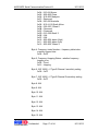
MPR Serial Communication Protocol III
-1-
9/11/2013
MPR Serial Communication Protocol III
- 041458
AWID MPR Serial Communication Protocol III
9/11/2013
Table of Contents
REVISION HISTORY............................................................................................ 4
1
PURPOSE AND SCOPE ...............................................................................5
1.1
DEFINITIONS AND ACRONYMS ............................................................................. 5
2
REFERENCES .............................................................................................. 6
3
PHYSICAL LAYER .......................................................................................7
4
DATA LINK LAYER ......................................................................................8
4.1
4.2
4.3
5
RCSP PACKET STRUCTURE ................................................................................. 8
CHECKSUM ALGORITHM ...................................................................................... 8
POLL RESPONSE ................................................................................................... 9
MESSAGE LAYER......................................................................................10
5.1
STOP COMMAND ................................................................................................ 11
Stop (0x00) ................................................................................................................ 11
5.2
SYSTEM COMMAND (0X00)................................................................................ 12
Firmware Version (0x00)......................................................................................... 12
Temperature (0x01) .................................................................................................. 13
RF Power ON (0x05) ................................................................................................ 14
RF Power OFF (0x06) .............................................................................................. 15
Reader Status (0x0B) ................................................................................................ 16
Antenna Select (0x0D) .............................................................................................. 19
Antenna Status (0x0E)............................................................................................... 20
Antenna Switch (0x0F).............................................................................................. 21
RF Power Level Control (0x12)................................................................................ 22
Portal IDs Filter (0x13) ............................................................................................ 23
Change Baud Rate (0x18) ......................................................................................... 24
Antenna Switch Rate (0x1D) ..................................................................................... 25
Write RF Power Level Control (0x32)...................................................................... 26
Report Temperature Warning (0x43)........................................................................ 27
Extended EPC Support (0x4A).................................................................................. 28
Antenna Source (0x53).............................................................................................. 29
Antenna Power Level Control (0x62) ....................................................................... 30
Soft Reset (0x80) ....................................................................................................... 31
Antenna Configure (0x88)......................................................................................... 32
5.3
ISO-18000-6 TYPE B (U-CODE, HSL) COMMAND (0X11)................................. 33
Read Single Tag ID (0x00) ....................................................................................... 33
Read Single Block Data (0x0D) ................................................................................ 34
Write Byte Data (0x0F)............................................................................................. 35
Single Tag Meter (0x11) ........................................................................................... 36
Portal IDs (0x1E)...................................................................................................... 37
Write Block (0x1F).................................................................................................... 39
Read N Blocks Data (0x2D)...................................................................................... 40
Confidential
Page 2 of 94
9/11/2013
AWID MPR Serial Communication Protocol III
9/11/2013
Write Bulk Data (0x5F) ............................................................................................ 42
5.4
EPC CLASS 1 GENERATION 2 COMMAND (0X20)............................................... 43
Read Single Tag ID (0x00) ....................................................................................... 43
Write ID (0x03) ......................................................................................................... 44
Lock ID (0x05) .......................................................................................................... 46
Kill Tag (0x06).......................................................................................................... 47
Sensitivity Control (0x07) ......................................................................................... 48
Write User Data (0x0F) ............................................................................................ 51
Read Single Tag ID with Time-Out (0x10) ............................................................... 53
Single Tag Meter (0x11) ........................................................................................... 54
Unlock ID (0x15) ...................................................................................................... 55
Read Memory (0x1D)................................................................................................ 56
Portal IDs (0x1E)...................................................................................................... 58
Write Kill Code (0x1F) ............................................................................................. 60
Lock Memory (0x25) ................................................................................................. 61
Write Access Code (0x2F) ........................................................................................ 63
Unlock Memory (0x35) ............................................................................................. 64
Permanent Lock Memory (0x55) .............................................................................. 65
Write Memory (0x5F) ............................................................................................... 67
Lock Memory with Action (0x65).............................................................................. 69
Read High Capacity Memory (0x6D) ....................................................................... 71
Write High Capacity Memory (0x6F) ....................................................................... 73
PermaLock User Data (0x9D) .................................................................................. 75
5.5
EPC CLASS 1 GEN 2 COMMANDS WITH PRE-SELECTION ................................... 78
Lock Memory with Mask (0x75) ............................................................................... 79
PermaLock User Data with Mask (0x76) ................................................................. 81
Read Memory with Mask (0x7D) .............................................................................. 85
Write Memory with Mask (0x8F) .............................................................................. 87
5.6
TEMPERATURE MONITOR STATUS MESSAGES ................................................... 89
Warning Notification (0x70) ..................................................................................... 89
System Halt Notification (0x7F) ............................................................................... 90
6
APPENDIX ..................................................................................................91
6.1
6.2
6.3
6.4
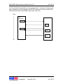
DATA FLOW ....................................................................................................... 91
MESSAGES RESPONSES ...................................................................................... 93
SIMPLE MULTI-PROTOCOL RFID APPLICATION SCENARIO ................................ 93
NOTE ON SENSITIVITY LEVEL CONTROL COMMAND (0X07).............................. 94
Confidential
Page 3 of 94
9/11/2013
AWID MPR Serial Communication Protocol III
9/11/2013
REVISION HISTORY
Version
No.
1.0
1.1
Date
Sections
Affected
-
8/2011
11/2011
2.0
1/2012
5.2
2.1
4/2012
5.2
3.0
5/2012
5.2, 5.6
3.1
6/2012
5.2
3.2
8/2012
5.2
4.0
4.1
4.2
9/2012
9/2012
9/2012
5.4
5.2
5.3, 5.4,
6.4
4.3
5.0
5.1
10/2012
1/2013
3/2013
5.2
-
6.0
6.1
9/2013
9/2013
5.3
5.2, 5.4
5.6
Confidential
Remarks
Initial version
Temperature monitor status messages
added
Conversion formula updated for handling
negative values – Temperature command
(0x01)
Editorial update to Regional Frequency
Band for Reader Status command; FW:
US0-V2.01-25.50.L6
System command (0x43) added for
enabling/disabling reporting temperature
status, FW 21.03.S1.T
System command (0x4A) added for
extended EPC support, FW 21.03.S3.T
Changes to antenna commands 0x0D,
0x0E (removed), 0x0F and 0x1D; 0x88
added for 4-port 19xx module support.
Obsolete EAS commands removed.
Antenna commands 0x0E, 0x62 added.
Appendix section added describing actual
indexing assignment for Sensitivity Level
Control command (0x07). FW 25.51.S8,
29.51.S8.
FW 25.51.L8
Corrections to 0x0F, 0x88 replies
Obsolete multi-protocol commands (0x14)
removed. FW 25.52.S1/29.52.S1
ISO commands updated per FW support
Obsolete system command 0x08
removed; EPC C1G2 commands 0x6D,
0x6F added
Page 4 of 94
9/11/2013
AWID MPR Serial Communication Protocol III
9/11/2013
1 Purpose and Scope
This document describes the serial (RS232) communication protocol for
communications among and between AWID’s Multi Protocol RFID (MPR) reading
devices and other HOST systems and equipment. Applicable devices are the
latest1 MPR-19xx module and complete reader2 embedding the module with
antenna in same housing and connector for optional external antenna.
A HOST system for purposes of this specification could be a personal computer,
a POS system or a data collector.
AWID MPR device reads tags of protocols/types3 listed below. Commands for
each of these protocols are further described in later sections.
ISO-18000-6 Type B (U-Code, HSL)
ISO-18000-6 Type C
EPC Class 1 Gen 2
The device handles one command a time, applications can be developed to
issue a sequence of commands of different categories (system, tag read/write,
etc.) with each command following receipt of response from the previous
command. See 6.3 for a simple scenario.
1.1
Definitions and Acronyms
Terms Used
Description of Terms
RFID
MPR
Radio Frequency IDentification
Multi Protocol RFID
RCSP
AWID’s RFID Common Serial Protocol
POS
Point Of Sale
1
HW version: 2.01 as of initial draft of this document.
MPR-2010BR, MPR-2080BU, etc.
3
For protocols used in testing for FCC certification, refer to Installation & Operation Manual for
each of the readers (modules).
2
Confidential
Page 5 of 94
9/11/2013
AWID MPR Serial Communication Protocol III
9/11/2013
2 References
Document Title
Document#
MPR Serial Communication Manual
041388
MPR Serial Communication Manual II
041377
Confidential
Page 6 of 94
9/11/2013
AWID MPR Serial Communication Protocol III
9/11/2013
3 Physical Layer
The device will be connected to the host via RS-232. It will be a three-wire
connection (TX, RX and GD) with 9600, 8, N, 1 as the default setting.
•
Baud Rate:
9600
•
Data Bits:
8
•
Parity:
None
•
Stop Bits:
1
•
Flow Control: None
Confidential
Page 7 of 94
9/11/2013
AWID MPR Serial Communication Protocol III
9/11/2013
4 Data Link Layer
This section describes the data link layer of the protocol. In particular it provides
sufficient information to describe how devices should implement the data
transmission mechanism in order to provide reliable communications of data.
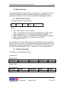
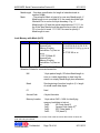
4.1 RCSP Packet Structure
The packet structure is shown below:
LEN
(1)
TYPE
(1)
CMD
(1)
DATA
(<50)
CHECKSUM
(2)
Where
LEN – Total number of bytes in packet
TYPE – Command type: commands are categorized into system (0x00),
tag type specific (0x11, 0x15 or 0x20) and multi-protocol (0x14).
CMD – Command code, i.e., command ID within the command category.
DATA – Data of 5~50 bytes long depending on the CMD.
CHECKSUM – CRC-16.
For example, the "RF Power ON" system command should be issued as "05 00
05 xx xx" where "05" in the 1st byte denotes the total bytes in packet, "00" in the
2nd byte the command's type: system, "05" in the 3rd byte the command id. The
final 2 bytes are placeholders for CRC. See section 5.1 for command details.
4.2
Checksum Algorithm
The checksum is calculated as follows:
Transmit Link:
CRC Definition:
CRC Type
Length
CCITT 16
16 bits = 2 bytes
Polynomial
0x1021
Preset
0xFFFF
Residue
0
Polynomial
0x1021
Preset
0xFFFF
Residue
0xFFFF
Receive Link:
CRC Definition:
CRC Type
Length
CCITT 16
16 bits = 2 bytes
Confidential
Page 8 of 94
9/11/2013
AWID MPR Serial Communication Protocol III
9/11/2013
The user can use the same routine to do the CRC generate and check. The
result for received packet check should be 0xFFFF when input the whole
received packet.
Example C program (for transmit):
//********************************************************************************************
unsigned int CRC_Check(unsigned char *ary,unsigned char len)
{
unsigned int crc;
unsigned char i,j;
crc = 0xFFFF;
for(i=0;i<len;i++,ary++)
{
crc = ((unsigned int)*ary << 8) ^ crc;
for(j=0;j<8;j++)
{
if(crc & 0x8000)
crc = (crc << 1) ^ 0x1021;
else
crc <<= 1;
}
}
return (crc ^ 0xFFFF);
}
//********************************************************************************************
Example:
Forward packet:
IN:
0x05, 0x00, 0x00
Out: 0xD8, 0x93
Received packet:
IN:
Out:
4.3
Poll Response
The protocol is poll-response only and therefore half-duplex. The MPR device
will respond with 0x00 or 0xFF after it receives the complete command
packet. The maximum delay the host has to wait for the response is about
100 ms.
Confidential
Page 9 of 94
9/11/2013
AWID MPR Serial Communication Protocol III
9/11/2013
5 Message Layer
This section describes all the commands that can be issued via RCSP packets.
They are categorized (or typed) into System, tag type (protocol) specific and
multi-protocol. Examples are shown in hexadecimal and include an xx in the
placeholder CRC bytes.
If data in a response message are for multiple tags, 1 tag's worth of data per
packet are returned. Data exceeding the length of the packet are truncated.
All commands should expect an acknowledgement from the MPR device, some
should also expect (a) subsequent response(s). These are noted in the
description for each of the commands in sub-sections that follow.
The Stop command is applicable to those commands that repeatedly execute
and/or generate multiple, continuous responses (see Appendix in section 6.1).
IDs, Portal IDs, Single Tag Meter, Read Single Tag ID, Write ID, Read Single
Block Data, Read N Blocks Data and Read Single Tag ID with Time-Out (with a
zero value specified for the TryTimes parameter for the last three) fall into this
sub-category and should be handled accordingly.
A response packet follows the same structure definition as illustrated in section
4.1 for a request command: 1st byte the number of bytes in response, 2 nd byte
the command type (system or protocol/tag type, e.g., 0x11 for ISO-B), 3rd byte
the command id (e.g., 0x0E for ISO-B’s IDs command), 4th through 3rd –from-last
the tag ID/data. For responses that do not contain tag ID data, the 2 nd byte is
0xFF indicating that this is (just) a message (i.e., no data), e.g., “06 FF 03 00 xx
xx" for the “Write Success” result of the ePC C1 Write ID command.
Confidential
Page 10 of 94
9/11/2013
AWID MPR Serial Communication Protocol III
9/11/2013
5.1 Stop Command
Before listing commands of System and tag type specific categories, the Stop
command is described due to the fact that it does not exactly fall into either
category. It should be noted that Stop is the only command the MPR reader
accepts any time (even multiple times) during operation with or without another
command in execution. It therefore serves as a simple way to verify the basic
well being of communication with an MPR device.
Issuing the Stop command is a required step to terminate those commands that
repeatedly execute and/or generate multiple, continuous responses (see
Appendix in section 6.1 Data Flow). IDs, Portal IDs, Single Tag Meter, Read
Single Tag ID, Write ID, Read Single Block Data, Read N Blocks Data and Read
Single Tag ID with Time-Out (with a zero value specified for the TryTimes
parameter for the last three) fall into this sub-category and should be handled
accordingly. For these commands4, until a Stop is issued and responded to, their
execution is not terminated and another command (system or tag type specific)
should not be issued as it most likely would produce undesirable outcome due to
data flow disruptions.
It is recommended that applications on exiting always check if there’s any
ongoing continuous tag reading activity and issue the essential Stop command if
so before the actual exit.
Stop (0x00)
FROM
Host
TO
Reader
MSG Example
00
ACK/RESPONSE Example
00
This one-byte (0x00) command is issued to stop the reader from executing
and sending any more data generated by the previously issued command.
Example:
Command:
00
ACK:
00
Response:
None
4
st
Also, a second Stop is advisable in these circumstances where the 1 Stop functions as
nd
described above and the 2 Stop ensures RF power’s being turned off. By the same token, a
good practice is to issue a Stop command after every command execution especially before a
subsequent tag read/write command as it basically achieves the tag re-set effect.
Confidential
Page 11 of 94
9/11/2013
AWID MPR Serial Communication Protocol III
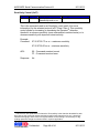
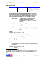
5.2
9/11/2013
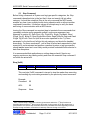
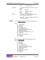
System Command (0x00)
Firmware Version (0x00)
FROM
Host
TO
Reader
Example:
Command:
MSG Example
05 00 00 xx xx
ACK/RESPONSE Example
00 or FF
17 00 00 55 53 30 2D 76 32
2E 30 31 2D 32 35 2A 35 30
2A 4C 31 xx xx
05 00 00 XX XX
ACK:
00 – Command received correct
FF – Command received error
Response:
17 00 00 55 53 30 2D 76 32 2E 30 31 2D 32 35 2A 35 30 2A 4C 31 xx xx
Where:
55 53 30 2D 76 32 2E 30 31 2D 32 35 2A 35 30 2A 4C 31
– Version Identification
In this example the result is “US0-v2.01-25*50*L1”
Confidential
Page 12 of 94
9/11/2013
AWID MPR Serial Communication Protocol III
9/11/2013
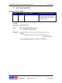
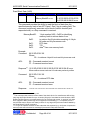
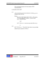
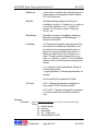
Temperature (0x01)
FROM
Host
TO
Reader
MSG Example
05 00 01 xx xx
ACK/RESPONSE Example
00 or FF
07 00 01 01 1D xx xx
This is the command to get the temperature5 reading of the MPR device in
centigrade.
Example:
Command:
05 00 01 XX XX
ACK:
00 – Command received correct
FF – Command received error
Response:
07 00 01 01 1D xx xx where the 4th byte is Temp1 and 5 th
byte Temp2 and the temperature reading should be
calculated as follows:
When Temp1 is less than 255 (0xFF) the resulting reader
temperature should be (Temp1*256 + Temp2)/10 (yields to
28 degrees Celsius from this response)
If Temp1 is a negative value the resulting reader
temperature should be –((256 – Temp2) / 10)
5
This refers to temperature of the embedded module and is ok to be higher (e.g., by 20°C) than
what’s documented in reader’s installation/user manual (sec 2) for (the upper limit of) the
operating (ambient) temperature.
Confidential
Page 13 of 94
9/11/2013
AWID MPR Serial Communication Protocol III
9/11/2013
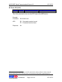
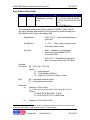
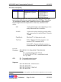
RF Power ON (0x05)
FROM
Host
TO
Reader
MSG Example
05 00 05 xx xx
ACK/RESPONSE Example
00 or FF
This is the command to turn on6 the RF Power of the MPR device.
Example:
Command:
05 00 05 XX XX
ACK:
00 – Command received correct
FF – Command received error
Response:
No
6
There is no need to explicitly turn on the RF power before issuing a Read or Write command
which automatically turns on the RF power. This command is only useful in generating CW.
Confidential
Page 14 of 94
9/11/2013
AWID MPR Serial Communication Protocol III
9/11/2013
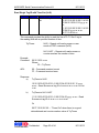
RF Power OFF (0x06)
FROM
Host
TO
Reader
Example:
Command:
MSG Example
05 00 06 xx xx
ACK/RESPONSE Example
00 or FF
05 00 06 XX XX
ACK:
00 – Command received correct
FF – Command received error
Response:
No
Confidential
Page 15 of 94
9/11/2013
AWID MPR Serial Communication Protocol III
9/11/2013
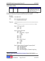
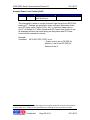
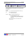
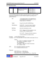
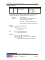
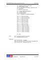
Reader Status (0x0B)
FROM
Host
TO
Reader
ACK/RESPONSE Example
00 or FF
19 00 0B 00 24 00 09 01 FF
FF FF FF FF FF FF FF FF FF
04 04 FF FF 00 xx xx
This is the command to retrieve current system settings for the reader. All except
for protocol data rate and frequency related fields are user settable.
Example:
Command:
MSG Example
05 00 0B xx xx
05 00 0B XX XX
ACK:
00 – Command received correct
FF – Command received error
Response:
19 00 0B 00 24 00 09 01 FF FF FF FF FF FF FF FF FF FF 04 04 FF FF 00 xx xx
Where:
00 24 00 09 01 FF FF FF FF FF FF FF FF FF FF 04 04 FF FF 00
- Status
Byte 1: RF Power On/Off
0x00 – Off
0x01 – On
Byte 2: Protocol Data Rate
Bit 0 – N/A
Bit 1 – ISO 18000 – 6 Type B
0: 40k
1: 160k
Bit 2 – N/A
Bit 3 – N/A
Bit 4 – N/A
Bit 5 – ePC C1 Gen 2
0: 40k
1: 20k
Bit 6 – N/A
Bit 7 – N/A
Byte 3: Region Code for Operation Frequency Band7
0x00 - 902~928 America8
0x01 - 902~928 US 2
0x02 - 922~928 Taiwan
0x03 - 920~925 Singapore, Thailand, Hong Kong
7
See http://www.gs1.org/docs/epcglobal/UHF_Regulations.pdf for up-to-date definitions.
Argentina, Canada, Chile, Costa Rica, Dominican Republic, Mexico, Peru, Puerto Rico, United
States, Uruguay.
8
Confidential
Page 16 of 94
9/11/2013
AWID MPR Serial Communication Protocol III
9/11/2013
0x04 - 910~914 Korea
0x05 – 920~925 China
0x06 – 919~923 Malaysia
0x07 – Reserved
0x08 - 920~926 Australia
0x09 – 915.4~919 South Africa
0x0A – 902~907.5 Brazil 1
0x0B – Reserved
0x0C – Reserved
0x0D – 915~928 Brazil 2
0x0E – N/A
0x0F – N/A
0x10 – 952~954 Japan (High)
0x11 – 952~955 Japan (Low)
0x12 – 922~926 Taiwan 3
Byte 4: Frequency Index Number – frequency table index
currently hopped to/at
0x00 ~ 0x32
Byte 5: Frequency Hopping Status – whether frequency
hopping is on
0x00 – Fixed
0x01 – Hopping
Byte 6: ISO 18000 – 6 Type B Channel I sensitivity setting
0x00 ~ 0xFF
Byte 7: ISO 18000 – 6 Type B Channel Q sensitivity setting
0x00 ~ 0xFF
Byte 8: N/A
Byte 9: N/A
Byte 10: N/A
Byte 11: N/A
Byte 12: N/A
Byte 13: N/A
Byte 14: N/A
Byte 15: N/A
Confidential
Page 17 of 94
9/11/2013
AWID MPR Serial Communication Protocol III
9/11/2013
Byte 16: RF Power level setting
0x00 ~ 0xFF
Byte 17: Write RF Power level setting
0x00 ~ 0xFF
Byte 18: ePC C1 Gen 2 Channel I sensitivity setting
0x00 ~ 0xFF
Byte 19: ePC C1 Gen 2 Channel Q sensitivity setting
0x00 ~ 0xFF
Byte 20: System Flag
Bit 0: N/A
Bit 1 – N/A
Bit 2 – Antenna Switch
0 – Disabled
1 – Enabled
Bit 3 –Antenna Source
0 – Disabled
1 – Enabled
Bit 4 – N/A
Bit 5 – N/A
Bit 6 – N/A
Bit 7 – N/A
Confidential
Page 18 of 94
9/11/2013
AWID MPR Serial Communication Protocol III
9/11/2013
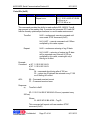
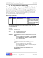
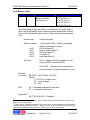
Antenna Select (0x0D)
FROM
Host
TO
Reader
MSG Example
06 00 0D Number xx xx
ACK/RESPONSE Example
00 or FF
06 FF 0D 00 xx xx or
06 FF 0D 10 xx xx
This command can be issued to a MPR-19xx based reader/module to select the
specified antenna (by Number) during operation when the Antenna Switch (toggle)
capability is disabled9. A 6-byte status message is responded by reader upon
executing this command, see example below.
Number:
1 or 2 for MPR-20x0BR or MPR-19x0
1 ~ 4 for MPR-1914
Example:
Command:
9
06 00 0D 02 xx xx
- to select Antenna 2
ACK:
00 – Command accepted for execution
FF – Command received in error
Response:
06 FF 0D 00 xx xx – selection made successfully
06 FF 0D 10 xx xx – selection failed (e.g., antenna not
configured)
By default the reader has Antenna Switch disabled and Antenna 1 selected.
Confidential
Page 19 of 94
9/11/2013
AWID MPR Serial Communication Protocol III
9/11/2013
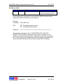
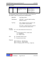
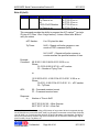
Antenna Status (0x0E)
FROM
Host
TO
Reader
MSG Example
05 00 0E xx xx
ACK/RESPONSE Example
00 or FF
11 00 0E 01 05 01 02 02 02
02 10 C8 DC C8 DC xx xx
This command is issued to retrieve the Status of Antennas of an MPR19x4 based unit. See below for definition of status data 10.
Example:
Command:
05 00 0E xx xx
Response: 11 00 0E 01 05 01 02 02 02 02 10 C8 DC C8 DC xx xx
Where:
01 05 01 02 02 02 02 05 05 05 05 10 C8 DC C8 DC FF FF FF FF
– status
Byte 1: Switching On/Off
0x00 – Off
0x01 – On
Byte 2: Current Antenna
0x01~0x04 – ID of current Antenna
Byte 3: Number of enabled Antennas
0x00~0x04
Byte 4~7: Switching Rate for each of the 4 Antennas
Byte 8: Bit Status Value for each of the 4 Antennas
Bit 0~7 –Status of Antenna 1~4
0: Disabled (not connected)
1: Enabled
Byte 9~12: antenna RF Power Level settings
10
Note that information on enabled/disabled antennas may not be correct until the Antenna
Configure command is executed.
Confidential
Page 20 of 94
9/11/2013
AWID MPR Serial Communication Protocol III
9/11/2013
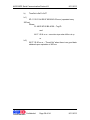
Antenna Switch (0x0F)
FROM
Host
TO
Reader
MSG Example
06 00 0F Setting xx xx
ACK/RESPONSE Example
00 or FF
07 00 0F 03 00 xx xx or,
07 00 0F 00 FF xx xx
This command is issued to enable or disable the Antenna Switch functionality for
reader/module. Setting is 00 for Disable and 01 for Enable. When enabled,
reader will use antenna by toggling between the two for 2-port reader/module or
among up to four for MPR-1914 (based on switching rates set for antennas). By
default, the switch is off and antenna 1 is selected. Upon executing this
command (to enable switching), reader responds with status information (3rd and
4th bytes) as shown in example below.
Example:
Command:
ACK:
06 00 0F 00 xx xx
06 00 0F 01 xx xx
- disable Antenna Switch
- enable Antenna Switch
00 – Command accepted for execution
FF – Command received in error
Response:
07 00 0F 03 00 xx xx where
3rd byte (0F) denotes command code
4th byte (03) denotes status of detected antennas11 and 5th
byte (00) setting status (or, result of command execution):
# of bytes
Description
Length
Type
Command
1
0x07
1
0x00
1
0x0F
Ant Detect
1
bit 0: ANT1
bit 1: ANT2
bit 2: ANT3
bit 3: ANT4
Message
CRC-16
1
0x00: Success
0xFF: Fail
2
1:Good12
0:No Good
11
st
nd
ANT3, ANT4 (bits 2, 3) applicable only to MPR-1914; example here shows 1 and 2 antennas
being “Good”.
12
Typically “Good” for when the numbered antenna is properly connected; “No Good” otherwise.
Confidential
Page 21 of 94
9/11/2013
AWID MPR Serial Communication Protocol III
9/11/2013
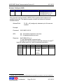
RF Power Level Control (0x12)
FROM
Host
TO
Reader
MSG Example
06 00 12 Index xx xx
ACK/RESPONSE Example
00 or FF
This is the command to control reader’s RF Power Level. The reader has
an adjustable Output Power range of 20 dB. The Index (for Output
Attenuation13) in this command is a one-byte value ranging from 0x00 to
0xFF that can be specified for the adjustment/control. The Output Power
decreases when the Index value increases. All subsequent tag
Read/Write14 operations will use this setting until re-set
Example:
Command:
06 00 12 00 xx xx – Maximum Output Power
06 00 12 FF xx xx – Minimum Output Power
ACK:
00 – Command received correct
FF – Command received error
Response:
No
13
Thus a value of zero (0) means no attenuation yielding maximum output power and 255 is
maximum attenuation for minimum output power.
14
If a Write RF Power Level has never been set.
Confidential
Page 22 of 94
9/11/2013
AWID MPR Serial Communication Protocol III
9/11/2013
Portal IDs Filter (0x13)
FROM
Host
TO
Reader
MSG Example
06 00 13 Filter xx xx
ACK/RESPONSE Example
00 or FF
This command can be issued to turn on or off the filtering for the Portal
IDs command. The MPR device is defaulted to have filtering enabled.
When filtering is in effect, a non-zero value for the Repeat parameter to
the Portal IDs command will result in a set of unique tag IDs being
returned every Repeat*100 ms.
Example:
Command:
06 00 13 00 xx xx – Filtering Off
06 00 13 01 xx xx – Filtering On
ACK:
00 – Command received correct
FF – Command received error
Response:
None
Confidential
Page 23 of 94
9/11/2013
AWID MPR Serial Communication Protocol III
9/11/2013
Change Baud Rate (0x18)
FROM
Host
TO
Reader
MSG Example
06 00 18
BaudrateIndex xx xx
ACK/RESPONSE Example
00 or FF
This is the command to set15 the baud rate for the MPR device. Mapping
between value for BaudrateIndex and the actual baud rate is as follows:
0x00 – 9600
0x01 - 19200
0x02 - 38400
0x03 – 57600
0x04 - 115200
Example:
Command:
15
06 00 18 02 XX XX to set the baud rate to 38400
ACK:
00 – Command received correct
FF – Command received error
Response:
None
The change will be reset back to 9600 after a power or soft reset.
Confidential
Page 24 of 94
9/11/2013
AWID MPR Serial Communication Protocol III
9/11/2013
Antenna Switch Rate (0x1D)
FROM
Host
TO
Reader
MSG Example
09 00 1D Ant1 Ant2
Ant3 Ant4 xx xx
ACK/RESPONSE Example
00 or FF
When Antenna Switch (0x0F) is enabled, the reader will operate switching
from one enabled antenna to the next based on the switching rate set for
each. This command is issued to set the switching rate for all the
antennas for an MPR-19xx based unit. Ant1 ~ Ant4 each takes value in
01~FF denoting Ant1*100 MS ~ Ant4*100 MS. All default to 5 for 500 MS.
Example:
Command:
09 00 1D 05 03 05 03 xx xx
- Antenna Switch Rate is 500 MS for oddnumbered antennas and 300 MS for evennumbered antennas.
Confidential
Page 25 of 94
9/11/2013
AWID MPR Serial Communication Protocol III
9/11/2013
Write RF Power Level Control (0x32)
FROM
Host
TO
Reader
MSG Example
06 00 32 Index xx xx
ACK/RESPONSE Example
00 or FF
RF Power Level set through command 0x12 applies to both Read and
Write operations, this command can be issued to control RF Power Level
specifically for Write operations. If neither 0x12 nor this command has
ever been issued the Write operation will use the system default of the
maximum RF Power Level.
Example:
Command:
06 00 32 00 xx xx – Maximum Output Power
06 00 32 FF xx xx – Minimum Output Power
ACK:
00 – Command received correct
FF – Command received error
Response:
None
Confidential
Page 26 of 94
9/11/2013
AWID MPR Serial Communication Protocol III
9/11/2013
Report Temperature Warning (0x43)
FROM
Host
TO
Reader
MSG Example
07 00 43 On/Off
Threshold xx xx
ACK/RESPONSE Example
00 or FF
This command is issued to enable/disable reporting of temperature
statuses (see 5.6 for applicable messages). On enabling, the reporting
temperature threshold should also be specified with a value in 40~90°
Celcius. By default, reporting is disabled in the system though steps are
always taken to constantly monitor the temperature and perform
necessary actions in safeguarding the system.
Example:
Command:
07 00 43 00 00 xx xx
07 00 43 01 32 xx xx
- disable reporting
- enable reporting at 50° Celcius
ACK:
00 – Command received correct
FF – Command received error
Response:
None
Confidential
Page 27 of 94
9/11/2013
AWID MPR Serial Communication Protocol III
9/11/2013
Extended EPC Support (0x4A)
FROM
Host
TO
Reader
MSG Example
06 00 4A Setting xx xx
ACK/RESPONSE Example
00 or FF
By default, reader reports EPC Class 1 Gen 2 tags with EPC numbers of
lengths in at most 128 bits. This command can be issued to override such
default for reader to include tags with EPC numbers in extended lengths of
up to 240 bits.
Example:
Command:
06 00 4A 00 xx xx
06 00 4A 01 xx xx
Response:
- disable extended length, report only
tags with EPC numbers of up to 128 bits
- enable extended length of 240 bits
None
Confidential
Page 28 of 94
9/11/2013
AWID MPR Serial Communication Protocol III
9/11/2013
Antenna Source (0x53)
FROM
Host
TO
Reader
MSG Example
06 00 53 Setting xx xx
ACK/RESPONSE Example
00 or FF
This command is issued to identify the antenna in use for a particular
Read of the tag. When enabled, the antenna number will be returned in
responses to a tag reading command taking up an additional byte. For
example, if enabled, the response for an ePC C1 Gen 2 Portal IDs
command is like “16 20 1E 30 00 11 22 33 44 55 66 77 88 99 AA BB CC
yy yy 01 xx xx” where “11 22 33 44 55 66 77 88 99 AA BB CC” is the tag
ID and “01” preceding the CRC bytes is the antenna number. Applicable
tag reading commands include IDs, Portal IDs, Read Single Tag ID, Read
Single Tag ID with Time Out. By default, this capability is disabled in the
system.
Example:
Command:
Response:
06 00 53 00 xx xx
06 00 53 01 xx xx
- disable Identifying Antenna Source
- enable Identifying Antenna Source
None
Confidential
Page 29 of 94
9/11/2013
AWID MPR Serial Communication Protocol III
9/11/2013
Antenna Power Level Control (0x62)
FROM
Host
TO
Reader
MSG Example
09 00 62 Ant1 Ant2
Ant3 Ant4 xx xx
ACK/RESPONSE Example
00 or FF
This command is issued to set the Antenna Power Level for an MPR-19x4
based unit16. Settings are specified in terms of Output Attenuation Index
as in RF Power Level Control (0x12). Ant1 ~ Ant4 each takes value in
00~FF. All default to 0. When system wide RF Power Level Control is set,
all antennas will have the same setting as the system wide RF Power
Level until this command is issued.
Example:
Command:
09 00 62 C8 DC C8 DC xx xx
- Power Level is set to C8 (200) for
Antenna 1 and 3 and DC (220) for
Antenna 2 and 4.
16
Execution of this command requires longer time for setting up the RF power for each antenna
so some delay (e.g., 100ms) is recommended before sending the next command to reader.
Confidential
Page 30 of 94
9/11/2013
AWID MPR Serial Communication Protocol III
9/11/2013
Soft Reset (0x80)
FROM
Host
TO
Reader
MSG Example
05 00 80 xx xx
ACK/RESPONSE Example
00 or FF
69 69 41 57 49 44 20 4D 50 52 2D 31 39 31 30 20
56 32 2E 30 41 20 55 48 46 20 4D 4F XX XX
Upon receiving this command, in one second the MPR will reset itself by
clearing all buffers and start from the beginning.
Example:
Command:
ACK:
05 00 80 XX XX
00 – Command received correct
FF – Command received error
Response:
69 69 41 57 49 44 20 4D 50 52 2D 31 39 31 30 20 56 32 2E 30 41 20 55 48 46 20 4D 4F XX XX
The greetings message in form of “iiAWID MPR 1910 V2.0A UHF
MODULE” (30-32 bytes) is sent back by the reader. Note that it is not
exactly a response to this particular command as for all other commands,
the 1st byte should not be interpreted as the total length of the packet and
the whole packet should just be converted through ASCII encoding.
Confidential
Page 31 of 94
9/11/2013
AWID MPR Serial Communication Protocol III
9/11/2013
Antenna Configure (0x88)
FROM
Host
TO
Reader
MSG Example
06 00 88 AntennaTotal xx xx
ACK/RESPONSE Example
00 or FF
07 00 88 0F 00 xx xx or,
07 00 88 00 FF xx xx
This command can be issued (to MPR-1914) to specify which antennas are
enabled/connected. The response packet contains two status info bytes as
illustrated below.
AntennaTotal:
01~04 – all (contiguous) antennas up to this one are
enabled
Example:
Command:
06 00 88 03 XX XX
ACK:
00 – Command accepted for execution
FF – Command received in error
Response:
07 00 88 07 00 xx xx
3rd byte (88) denotes command code
4th byte (07) denotes status of detected antennas (3) and 5th
byte (00) setting status (or, result of command execution):
# of bytes
Description
Length
Type
Command
1
0x07
1
0x00
1
0x88
Ant Detect
1
bit 0: ANT1
bit 1: ANT2
bit 2: ANT3
bit 3: ANT4
Message
CRC-16
1
0x00: Success
0xFF: Fail
2
1:Good17
0:No Good
17
Typically “Good” for when the numbered antenna is properly connected; “No Good” otherwise.
Confidential
Page 32 of 94
9/11/2013
AWID MPR Serial Communication Protocol III
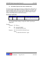
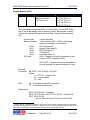
5.3
9/11/2013
ISO-18000-6 Type B (U-Code, HSL) Command (0x11)
This family of tags includes tags from Intermec’s Intellitag family, Philips HSL and
any future suppliers of ISO-18000-6 Type B family. Dash six (-6) is for UHF, and
Type B is the family distinct from those of Type A. Traditionally, Type B is called
binary tree splitting and Type A is called Aloha anti-collision. Philips U-Code is
similar to the Intellitag family, but with 2K-bits memory.
Read Single Tag ID (0x00)
FROM
Host
TO
Reader
MSG Example
05 11 00 xx xx
ACK/RESPONSE Example
00 or FF
0D 11 00 01 A8 E5 8F 80 D8 40 09
xx xx
This command enables reading of a single ISO-18000-6 Type B tag in
reading field.
Example –
Command:
05 11 00 xx xx
Ack:
00 – command accepted
FF – command received in error
Response:
0D 11 00 01 A8 E5 8F 80 D8 40 09 xx xx
Where
01 A8 E5 8F 80 D8 40 09 – tag ID
Confidential
Page 33 of 94
9/11/2013
AWID MPR Serial Communication Protocol III
9/11/2013
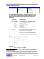
Read Single Block Data (0x0D)
FROM
Host
TO
Reader
MSG Example
11 11 0D 0C ID
StartAddress DataCRC
xx xx
ACK/RESPONSE Example
00 or FF
0F 11 0D 01 02 03 04 05 06
07 08 yy yy xx xx
This command provides the ability to read single memory block which is
total 8 bytes starting from StartAddress of the selected ISO-18000-6 Type
B Tag ID in the reading field. The command continuously executes until a
block of data is located (and responded with) or a Stop command is
received.
Example:
Command:
11 11 0D 0C 01 A8 E5 8F 80 B8 40 09 12 39 4B XX XX
Where:
01 A8 E5 8F 80 B8 40 09 – Tag ID
12 – Start Address
39 4B – Data CRC18
ACK:
00 – Command received correct
FF – Command received error
Response:
0F 11 0D 01 02 03 04 05 06 07 08 yy yy xx xx
Where:
01 02 03 04 05 06 07 08 – Block Data
yy yy – internal CRC (2 bytes)
18
th
The Data CRC is calculated with 10 bytes of data: 0C (4 in command preceding the 8-byte
th
th
th
th
th
Tag ID), Tag ID (5 -12 ) and the Start Address byte (13 ) and will be placed in the 14 and 15
bytes of the command.
Confidential
Page 34 of 94
9/11/2013
AWID MPR Serial Communication Protocol III
9/11/2013
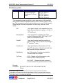
Write Byte Data (0x0F)
FROM
Host
TO
Reader
MSG Example
12 11 0F 0D TagID
WriteAddress
WriteData DataCRC xx
xx
ACK/RESPONSE Example
00 or FF
06 FF 0F Status xx xx
This command provides the ability to write single byte data to the Write
Address of the selected Tag ID in the writing field.
TagID:
8-byte TagID
WriteAddress:
0x08~0xFF - 1-byte address19 to write at
WriteData:
1-byte data to write with
DataCRC:
2-byte CRC’s calculated with 11 bytes of data:
0D (4th in the command preceding the 8-byte
Tag ID), Tag ID (5th-12th), the Write Address
byte (13th) and the Write Data byte (14th) and
will be placed in the15th and 16th bytes of the
command.
Example:
Command:
19
12 11 0F 0D 01 A8 E5 8F 80 B8 40 09 12 31 0C 4E XX XX
Where:
01 A8 E5 8F 80 B8 40 09 – Tag ID
12 – WriteAddress
31 – WriteData
0C 4E – DataCRC
ACK:
00 – Command received correct
FF – Command received error
Response:
06 FF 0F Status xx xx
Where:
Status:
00 – Write Success
10 or FF – Write Fail
80 – No response from Tag
Actual write-able area starts at 0x08 past Tag ID bytes that’re read only.
Confidential
Page 35 of 94
9/11/2013
AWID MPR Serial Communication Protocol III
9/11/2013
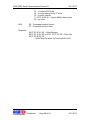
Single Tag Meter (0x11)
FROM
Host
TO
Reader
MSG Example
12 11 11 00 00 00 00
00 00 00 00 00 00 00
2B F0 xx xx
ACK/RESPONSE Example
00 or FF
0E 11 11 01 A8 E5 8F 80 B8
40 09 20 xx xx
This command provides the ability to read and count the number of times
which single ISO-18000-6 Type B tag has been read in 300ms duration in
the reading field.
Example:
Command:
12 11 11 00 00 00 00 00 00 00 00 00 00 00 2B F0 xx xx
ACK:
00 – Command received correct
FF – Command received error
Response:
0E 11 11 01 A8 E5 8F 80 B8 40 09 20 xx xx
Where:
01 A8 E5 8F 80 B8 40 09 – Tag ID
20 – Number of Reads in 300ms period of the same
tag reading until other tags detected before 300ms
period ends
This command will repeat until user sends a STOP
command (0x00).
Confidential
Page 36 of 94
9/11/2013
AWID MPR Serial Communication Protocol III
9/11/2013
Portal IDs (0x1E)
FROM
Host
TO
Reader
MSG Example
07 11 1E TimeOut
Repeat xx xx
ACK/RESPONSE Example
00 or FF
0D 11 1E 01 A8 E5 8F 80 B8
40 09 xx xx or
06 FF 1E 80 xx xx
This command provides the ability to read multiple ISO-18000-6 Type B
tags present in the reading field. It provides the automatic RF Power Off
function thereby optimizes performance in a multi-reader environment.
TimeOut:
0x00 – continuously execute command until
user sends STOP command (0x00)
0x01~0xFF – execute command until 100ms
multiplied by this value expires
Repeat:
0x00 – continuous returning of tag ID data
0x01~0xFE – returning of unique tag ID data
will be repeated every interval of 100 ms
multiplied by this value, meaningful only if
filtering is in effect
Example:
Command:
ACK:
a) 07 11 1E 00 00 XX XX
b) 07 11 1E 04 03 XX XX
Where:
04 – command should stop after 4*100 ms
03 – unique tag ID data will be returned every 3*100
ms if filtering is in effect
00 – Command received correct
FF – Command received error
Response:
a)
TimeOut is 0x00
0D 11 1E 01 A8 E5 8F 80 B8 40 09 xx xx (repeated every
300 ms)
Where:
01 A8 E5 8F 80 B8 40 09 – Tag ID
This command will repeat until user sends a STOP
command (0x00).
Confidential
Page 37 of 94
9/11/2013
AWID MPR Serial Communication Protocol III
b)
9/11/2013
TimeOut is 0x01~0xFF
b.1)
0D 11 1E 01 A8 E5 8F 80 B8 40 09 xx xx (repeated every
300 ms)
Where:
01 A8 E5 8F 80 B8 40 09 – Tag ID
and
06 FF 1E 80 xx xx – execution stops when 400 ms is up
b.2)
or
06 FF 1E 80 xx xx – “Timed Out” when there is no good data
obtained upon expiration of 400 ms
Confidential
Page 38 of 94
9/11/2013
AWID MPR Serial Communication Protocol III
9/11/2013
Write Block (0x1F)
FROM
Host
TO
Reader
MSG Example
0F 11 1F 8ByteData
StartAddress TryTimes
xx xx
ACK/RESPONSE Example
00 or FF
06 FF 1F 00 xx xx
06 FF 1F 10 xx xx
06 FF 1F 80 xx xx
06 FF 1F FF xx xx
This command provides the ability to write eight (8) bytes of data to an
ISO-18000-6 Type B Tag starting at the specified address.
8ByteData:
8-byte data to write
StartAddress:
0x08~0xFF - 1 byte Hex data for starting
address to write at
TryTimes:
0x00 – Repeat until write success or user
sends a STOP command (0x00)
0x01~0xFF – Repeat until write success or
counter reaches the number of tries
Example:
Command:
0F 11 1F 01 02 03 04 05 06 07 08 12 0A xx xx
Where:
01 02 03 04 05 06 07 08 – data to write
12 – StartAddress
0A – number of tries
ACK:
00 – Command received correct
FF – Command received error
Response:
06 FF 1F 00 xx xx – Write Success
06 FF 1F 80 xx xx – Write Time-Out
06 FF 1F 10 xx xx or 06 FF 1F FF xx xx – Write Fail
Confidential
Page 39 of 94
9/11/2013
AWID MPR Serial Communication Protocol III
9/11/2013
Read N Blocks Data (0x2D)
FROM
Host
TO
Reader
MSG Example
08 11 2D StartAddress
TotalBlocks TryTimes
xx xx
ACK/RESPONSE Example
00 or FF
15 11 2D 01 A8 E5 8F 80 B8
40 09 01 02 03 04 05 06 07 08
xx xx
06 FF 2D 80 xx xx
This command provides the ability to read ISO-18000-6 Type B Tag ID
plus up to specified total number of (8-byte) memory blocks starting from
StartAddress of the Tag in the reading field.
StartAddress:
0x00 ~ 0xFF – 1-byte starting address to
read from
Total Blocks:
1 ~ 1C20 – 1-byte value for total number
of blocks of data to read
TryTimes:
0x00 – Repeating until good data
obtained or user sends a STOP
command (0x00)
0x01~0xFF – Repeating until get good
data or counter reaches the TryTimes.
Example:
Command:
ACK:
08 11 2D 12 01 10 XX XX
Where:
12 – Start Address
01 – Total Number of Blocks
10 – Value for TryTimes (number of tries)
00 – Command received correct
FF – Command received error
Response:
a)
Number of Tries is 0x00
15 11 2D 01 A8 E5 8F 80 B8 40 09 01 02 03 04 05 06 07 08 xx xx
Where:
01 A8 E5 8F 80 B8 40 09 – Tag ID
01 02 03 04 05 06 07 08 – Block Data
b)
Number of Tries is 0x01~0xFF
20
The maximum value 0x1C (28) is based on reading at address 0 and up to 216 bytes of data
could have been written (command 0x5F) starting at address 0x08.
Confidential
Page 40 of 94
9/11/2013
AWID MPR Serial Communication Protocol III
9/11/2013
15 11 2D 01 A8 E5 8F 80 B8 40 09 01 02 03 04 05 06 07 08 xx xx
Where:
01 A8 E5 8F 80 B8 40 09 – Tag ID
01 02 03 04 05 06 07 08 – Block Data
Or
06 FF 2D 80 xx xx
represents a “time-out when counter reaches value of
TryTimes and no good data obtained.
Confidential
Page 41 of 94
9/11/2013
AWID MPR Serial Communication Protocol III
9/11/2013
Write Bulk Data (0x5F)
FROM
Host
TO
Reader
MSG Example
NN 11 5F TagID
StartAddress BulkData
TryTimes xx xx
ACK/RESPONSE Example
00 or FF
06 FF 5F 00 xx xx
06 FF 5F 10 xx xx
06 FF 5F 80 xx xx
06 FF 5F FF xx xx
This command provides the ability to write large amount of data of variable
length (up to 216 bytes) to an ISO-18000-6 Type B Tag starting at the
specified address.
NN:
1-byte packet length, value depending on
much ‘BulkData’ is to be written, i.e., 15 +
length (#bytes) of ‘BulkData’
TagID:
8-byte ID of the ISO-18000-6B tag
StartAddress:
0x08~0xFF - 1 byte Hex data of starting
address at which data are to be written
BulkData:
the bulk of data bytes to write
TryTimes:
0x00 – Repeat until write success or user
sends a STOP command (0x00)
0x01~0xFF – Repeat until write success or
counter reaches the number of tries
Example:
Command:
to write 168 bytes of data
B7 11 5F E0 04 DB 2F C9 00 00 00 08 <bulk data> 00 xx xx
Where:
B7 – 183 = 15 + length of <bulk data>: 168
E0 04 DB 2F C9 00 00 00 – tag ID
08 – StartAddress
<bulk data> - 168 bytes of data to be written
00 – number of tries
ACK:
00 – Command accepted for execution
FF – Command received in error
Response:
06 FF 5F 00 xx xx – Write Succes
06 FF 5F 80 xx xx – Write Time-Out
5.306 FF 5F 10 xx xx or 06 FF 5F FF xx xx – Write Fail
Confidential
Page 42 of 94
9/11/2013
AWID MPR Serial Communication Protocol III
9/11/2013
5.4 EPC Class 1 Generation 2 Command (0x20)
This section and next list commands supported for the EPC Class 1 Generation 2
protocol. For those Tag ID specific commands (0x00, 0x10, 0x11, 0x1E, 0x5E,
etc.) that result in Tag ID(s), i.e., EPC Number(s) reported back in response(s),
the 2-byte Protocol Code (PC) is always preceding the Tag ID (EPC Number)
bytes and the actual length (in number of words) of Tag ID/EPC Number can be
obtained by extracting the number constituted by the first 5 bits of the first PC
byte. In examples below, PC code with value 0x30 in first byte yields 6 words
(i.e., 12 bytes or 96 bits) as EPC Number’s length.
Read Single Tag ID (0x00)
FROM
Host
TO
Reader
MSG Example
05 20 00 xx xx
ACK/RESPONSE Example
00 or FF
15 20 00 30 00 30 00 21 41 60
C0 04 00 10 00 01 15 yy yy xx
xx or,
11 20 00 20 00 30 00 21 41 60
C0 04 00 yy yy xx xx
This command provides the ability to read single ePC Class 1 Gen 2 tag
ID in the reading field.
Example:
Command:
05 20 00 XX XX
ACK:
00 – Command received correct
FF – Command received error
Response:
15 20 00 30 00 30 00 21 41 60 C0 04 00 10 00 01 15 yy yy xx xx
Where:
30 00 21 41 60 C0 04 00 10 00 01 15 – ePC Number
30 00 (preceding ePC number) – Protocol Code (PC)
yy yy – tag CRC bytes
or,
11 20 00 20 00 30 00 21 41 60 C0 04 00 yy yy xx xx
Where:
30 00 21 41 60 C0 04 00 – ePC Number
20 00 (preceding ePC number) – Protocol Code (PC)
yy yy – tag CRC bytes
This command will repeat until user sends a STOP
command (0x00)
Confidential
Page 43 of 94
9/11/2013
AWID MPR Serial Communication Protocol III
9/11/2013
Write ID (0x03)
FROM
Host
TO
Reader
MSG Example
0E 20 03 ePCNumber
TryTimes xx xx
or,
12 20 03 ePCNumber
TryTimes xx xx
ACK/RESPONSE Example
00 or FF
06 FF 03 00 xx xx
06 FF 03 10 xx xx
06 FF 03 80 xx xx
06 FF 03 FF xx xx
This command provides the ability to program the ePC number21 (as tag’s
ID) into ePC Class 1 Gen 2 tag’s memory. It does a Read after Write to
verify the status.
ePC Number:
8 or 12 bytes Hex data
TryTimes:
0x00 – Repeat until write success or user
sends a STOP command (0x00)
0x01~0xFF – Repeat until write success or
counter reaches the specified number of tries
Example:
Command:
0E 20 03 01 02 03 04 05 06 07 08 03 xx xx
Where:
01 02 03 04 05 06 07 08 – ePC number
03 – Number of Trying Time
or
12 20 03 30 00 21 41 60 C0 04 00 10 00 01 16 00 xx xx
Where:
30 00 21 41 60 C0 04 00 10 00 01 16 – ePC number
00 - TryTimes
ACK:
00 – Command received correct
FF – Command received error
Response:
a)
Number of Tries is 0x00
06 FF 03 00 XX XX – Write Success
06 FF 03 FF XX XX – Write Fail
21
It should be noted that though writing ePC Number of longer than 96 bits is supported through
use of Write Memory commands (0x5F, 0x8F) tag ID specific commands such as Write ID (0x03),
Lock ID (0x05), etc. only allows either 64-bit or 96-bit ePC Numbers to be specified. The latter is
also true for performance sensitive tag read commands such as Portal IDs, Read Single Tag ID
(with TimeOut), Single Tag Meter, etc.
Confidential
Page 44 of 94
9/11/2013
AWID MPR Serial Communication Protocol III
b)
9/11/2013
Number of Tries is 0x01~0xFF
06 FF 03 00 XX XX – Write Success
06 FF 03 10 XX XX – Write Fail
Or
06 FF 03 80 XX XX – Counter reaches value of TryTimes
Confidential
Page 45 of 94
9/11/2013
AWID MPR Serial Communication Protocol III
9/11/2013
Lock ID (0x05)
FROM
Host
TO
Reader
MSG Example
0A 20 05 AccessCode
TryTimes xx xx
ACK/RESPONSE Example
00 or FF
06 FF 05 00 xx xx
06 FF 05 10 xx xx
06 FF 05 80 xx xx
06 FF 05 FF xx xx
This command provides the ability to Lock ID of an ePC Class 1 Gen 2 tag
in the reading field with an Access Code defined through a previous Write
Access Code command (2F).
AccessCode:
TryTimes:
4 bytes Hex data
0x00 – Repeat until lock completes or user
sends a STOP command (0x00)
0x01~0xFF – Repeat until lock completes or
counter reaches the specified number of tries
Example:
Command:
ACK:
0A 20 05 11 22 33 44 14 XX XX
Where:
11 22 33 44 – access code
14 - tries
00 – Command received correct
FF – Command received error
Response22:
06 FF 05 00 XX XX – Complete
06 FF 05 10 XX XX or 06 FF 05 FF XX XX – Lock Fail
06 FF 05 80 XX XX
– Lock Time-Out when TryTimes is 0x01~0xFF
22
Status value of 0 indicates completion of execution of the lock command and not necessarily
the actual resulting status of the tag; i.e., tag may or may not be successfully locked. Any of the
other status values was mostly caused by a failed communication with the tag.
Confidential
Page 46 of 94
9/11/2013
AWID MPR Serial Communication Protocol III
9/11/2013
Kill Tag (0x06)
FROM
Host
TO
Reader
MSG Example
0A 20 06 KillCode
TryTimes xx xx
ACK/RESPONSE Example
00 or FF
06 FF 06 00 xx xx
06 FF 06 10 xx xx
06 FF 06 FF xx xx
06 FF 06 80 xx xx
This command provides the ability to Kill23 the ePC C1 Gen 2 tag in
reading field with a 4-byte Kill Code defined through a previous Write Kill
Code command (1F).
KillCode:
TryTimes:
4-byte hex data
0x00 – Repeat until kill success or user sends
a STOP command (0x00)
0x01~0xFF – Repeat until kill success or
counter reaches the specified number of tries
Example:
Command:
ACK:
00 – Command received correct
FF – Command received error
Response:
23
0A 20 06 01 02 03 04 00 xx xx
Where:
01 02 03 04 – Kill Code
00 - TryTimes
06 FF 06 00 XX XX – Kill Success
06 FF 06 10 XX XX or 06 FF 06 FF XX XX – Kill Fail
06 FF 06 80 XX XX
– Kill Time-Out when TryTimes is 0x01~0xFF
The tag becomes unusable afterwards.
Confidential
Page 47 of 94
9/11/2013
AWID MPR Serial Communication Protocol III
9/11/2013
Sensitivity Control (0x07)
FROM
Host
TO
Reader
MSG Example
07 20 07 00
SensitivityLevel xx xx
ACK/RESPONSE Example
00 or FF
This is the command used to set Sensitivity Level (see 6.4 for more
information) for the selected protocol (ePC Class1 Gen 2. This sensitivity
control allows for increasing or decreasing the Receiver 24 detection
threshold, to enhance sensitivity (more susceptible to ambient noise) or to
decrease sensitivity with improved noise immunity.
Example:
Command:
07 20 07 00 FF xx xx – maximum sensitivity
07 20 07 00 00 xx xx – minimum sensitivity
ACK:
00 – Command received correct
FF – Command received error
Response:
No
24
This receiver uses quadrature I/Q channels. I/Q sensitivity is the detection threshold for each.
Once issued, the command causes sensitivity levels for both channels to be set. It should be
noted that changing to other value from system default for this setting is unnecessary for tag
reading operations though sometimes useful in a printer application.
Confidential
Page 48 of 94
9/11/2013
AWID MPR Serial Communication Protocol III
Read Block Data (0x0D)
FROM
TO
Host
Reader
MSG Example
06 20 0D
MemoryBankID xx xx
9/11/2013
ACK/RESPONSE Example
00 or FF
12 20 0D 00 00 00 00 00 00
00 00 0E A9 99 0A 80 xx xx
This command provides the ability to read the block of data from the
specified memory bank of an ePC Class 1 Gen 2 tag in reading field. The
command continuously executes until a block of data is located (and
responded with) or a Stop command is received.
MemoryBankID:
0x00:
0x01:
0x02:
0x03:
Example:
Command:
ACK:
1-byte number 0x00 ~ 0x03 for identifying
memory bank to retrieve data25 from.
to retrieve the 8-byte data consisting of 4-bytekill-code and 4-byte-access-code
EPC data
TID
data26 from user memory bank
06 20 0D 00 XX XX
Where:
00 – to retrieve 4-byte-kill-code and 4-byte-access-code
00 – Command received correct
FF – Command received error
Response27: 12 20 0D 00 00 00 00 00 00 00 00 0E A9 99 0A 80 xx xx
Where neither access code nor kill code was previously written
Command:
06 20 0D 01 XX XX
Where:
01 – to retrieve EPC data
ACK:
00 – Command received correct
FF – Command received error
Response:
1A 20 0D 13 34 18 00 00 08 91 19 A2 2A B3 3B C4 4C D5 5D ED 89 47 E0 80 xx xx
25
Data need to be shifted to left by 1 bit.
This command was meant to retrieve data of the whole block of a manufacturer defined size,
early tags by Philips allowed for up to 14 words (28 byte) of user data be stored however, MPR
Readers would reject any command packet of over 30 bytes and at most 11 words of user data
were supported. Many newer tags do not support this functionality (i.e., no response) since a
more flexible way to retrieve user data (could be of very large size) has been made available by
the Read Memory (0x1D) command.
27
st
If 1 byte of response contains a value other than the expected (e.g., 0x12) then it implies the
memory bank was locked and no meaningful (access+kill code) data retrieved.
26
Confidential
Page 49 of 94
9/11/2013
AWID MPR Serial Communication Protocol III
9/11/2013
Where tag ID 00 11 22 33 44 55 66 77 88 99 AA BB was previously written
Command:
06 20 0D 02 XX XX
Where:
02 – to retrieve TID
ACK:
00 – Command received correct
FF – Command received error
28
Response29: 12 20 0D 71 00 20 00 80 0F 5A 60 BB 73 66 5B 00 xx xx
or
0E 20 0D 71 00 08 20 05 DE A7 90 80 xx xx
Command:
06 20 0D 03 xx xx
Where:
03 – to retrieve user data
ACK:
00 – Command received correct
FF – Command received error
Response:
26 20 0D 00 08 88 88 88 88 88 88 88 99 38 57 00 00 00 00 00 00 00 00 00 00 00 00 00 00
00 00 31 67 1B 78 80 xx xx
Where 8-byte user data of all 1’s were previously written at word 0
28
Therefore after shifting data should be 26 68 30 00 00 11 22 33 44 55 66 77 88 99 AA BB DB
12 8F C1 where 30 00 are the PC number, DB 12 are the 2-byte handle (a random value), etc. for
details refer to ePC C1 Gen 2 protocol definition.
29
Length of response packet in this case is manufacturer dependent, first example response is
from a Philip’s tag and after shifting, data should be E2 00 40 01 00 1E B4 C1 75 E6 CC B6
where 73 66 (unshifted) would be the 2-byte handle (random value), 5B 00 tag CRC’s. Second
example response is from a TI tag and data after shifting are E2 00 10 40 0B BD 4F 21 where DE
A7 are the handle bytes. For others refer to ePC C1 Gen 2 protocol definition for details.
Confidential
Page 50 of 94
9/11/2013
AWID MPR Serial Communication Protocol III
9/11/2013
Write User Data (0x0F)
FROM
Host
TO
Reader
MSG Example
NN 20 0F WordID
DataWords TryTimes
xx xx
ACK/RESPONSE Example
00 or FF
06 FF 0F 00 xx xx
06 FF 0F 10 xx xx
06 FF 0F 80 xx xx
06 FF 0F FF xx xx
This command provides the ability to write data starting at the specified
word position within the user memory bank of an ePC Class 1 Gen 2 tag.
The command is issued to write at least one or more (2-byte) word(s).
Packet length is therefore dependent on how many words are to be
written.
NN:
1-byte packet length, value depending on how
many data words are to be written
WordID:
1-byte word number identifying position within
user memory bank to start writing at, 0 denotes
1st word
DataWords:
Word data30 in 2-byte pairs to write
TryTimes:
0x00 – Repeat until write success or user
sends a STOP command (0x00)
0x01~0xFF – Repeat until write success or
counter reaches the specified number of tries
Example:
Command:
ACK:
0F 20 0F 02 11 22 33 44 55 66 77 88 00 XX XX
Where:
02 – to write starting at the 3rd word
11 22 33 44 55 66 77 88 – 4-word data to write
00 – try times
00 – Command received correct
FF – Command received error
Response:
06 FF 0F 00 XX XX – Write Success
06 FF 0F 10 XX XX or
06 FF 0F FF XX XX – Write Fail
06 FF 0F 80 XX XX –
30
A manufacturer dependent upper limit applies, up to 20 words are supported per one command
execution.
Confidential
Page 51 of 94
9/11/2013
AWID MPR Serial Communication Protocol III
9/11/2013
WriteTime-Out when TryTimes is 0x01~0xFF
Confidential
Page 52 of 94
9/11/2013
AWID MPR Serial Communication Protocol III
9/11/2013
Read Single Tag ID with Time-Out (0x10)
FROM
Host
TO
Reader
MSG Example
06 20 10 TryTimes xx
xx
ACK/RESPONSE Example
00 or FF
15 20 10 30 00 30 00 21 41 60
C0 04 00 10 00 0115 yy yy xx
xx,
11 20 10 20 00 30 00 21 41 60
C0 04 00 yy yy xx xx or
06 FF 10 80 xx xx
This command provides the ability to read the first ePC C1 Gen 2 tag in
the reading field with a specified number of tries.
TryTimes:
0x00 – Repeat until read success or user
sends a STOP command (0x00)
0x01~0xFF – Repeat until read success or
counter reaches the number of tries
Example:
Command:
ACK:
06 20 10 03 xx xx
Where:
03 – TryTimes
00 – Command received correct
FF – Command received error
Response:
a)
TryTimes is 0x00
15 20 10 30 00 30 00 21 41 60 C0 04 00 10 00 01 15 yy yy
xx xx – Read Success w/ tag ID of 30 00 30 00 21 41 60 C0 04 00
10 00
b)
TryTimes is 0x01~0xFF
11 20 10 20 00 30 00 21 41 60 C0 04 00 yy yy xx xx – Read
Success w/ tag ID of 30 00 21 41 60 C0 04 00
Or
06 FF 10 80 XX XX – “Times Out” when there is no good
data obtained and counter reaches value of TryTimes
Confidential
Page 53 of 94
9/11/2013
AWID MPR Serial Communication Protocol III
9/11/2013
Single Tag Meter (0x11)
FROM
Host
TO
Reader
MSG Example
05 20 11 xx xx
ACK/RESPONSE Example
00 or FF
16 20 11 30 00 00 01 08 15 80
00 80 04 28 19 53 88 yy yy 3F
xx xx
This command provides the ability to read and count the number of times
which single ePC Class 1 Gen 2 tag has been read in 300ms duration in
reading field.
Example:
Command:
05 20 11 XX XX
ACK:
00 – Command received correct
FF – Command received error
Response:
16 20 11 30 00 00 01 08 15 80 00 80 04 28 19 53 88 yy yy 3F xx xx
Where:
00 01 08 15 80 00 80 04 28 19 53 88 – ePC number
30 00 (preceding ePC number) – PC
yy yy – tag CRC bytes
3F – Number of Reads in 300ms period or the same
tag reading until other tags detected before 300ms
period ends
Confidential
Page 54 of 94
9/11/2013
AWID MPR Serial Communication Protocol III
9/11/2013
Unlock ID (0x15)
FROM
Host
TO
Reader
MSG Example
0A 20 15 AccessCode
TryTimes xx xx
ACK/RESPONSE Example
00 or FF
06 FF 15 00 xx xx
06 FF 15 10 xx xx
06 FF 15 80 xx xx
06 FF 15 FF xx xx
This command provides the ability to Unlock the ID of a locked ePC Class
1 Gen 2 tag in reading field with an Access Code defined through a
previous Write Access Code command (2F).
AccessCode:
4-byte hex data
TryTimes:
0x00 – Repeat until unlock completes or user
sends a STOP command (0x00)
0x01~0xFF – Repeat until unlock completes or
counter reaches the specified number of tries
Example:
Command:
ACK:
0A 20 15 11 22 33 44 14 XX XX
Where:
11 22 33 44 – access code
14 - tries
00 – Command received correct
FF – Command received error
Response31:
06 FF 15 00 XX XX – Complete
06 FF 15 10 XX XX or 06 FF 15 FF XX XX – Unlock Fail
06 FF 15 80 XX XX
– Unlock Time-Out when TryTimes is 0x01~0xFF
31
Status value of 0 indicates completion of execution of the unlock command and not necessarily
the actual resulting status of the tag; i.e., tag may or may not be successfully unlocked. Any of the
other status values was mostly caused by a failed communication with the tag.
Confidential
Page 55 of 94
9/11/2013
AWID MPR Serial Communication Protocol III
9/11/2013
Read Memory (0x1D)
FROM
Host
TO
Reader
MSG Example
08 20 1D MemoryBank
WordAddress
WordCount xx xx
ACK/RESPONSE Example
00 or FF
1A 20 1D 11 11 11 11 11 11
11 11 11 11 22 22 22 22 00 00
52 16 D3 A1 00 xx xx
This command provides the ability to read data of specified word length
from the specified location in the specified memory bank of an ePC Class
1 Gen 2 tag in reading field. The command continuously executes until
data is located (and responded with) or a Stop command is received.
MemoryBank:
1-byte specification of memory bank from
which data will be retrieved. 0x00 for
Reserved, 0x01 EPC, 0x02 TID or 0x03 for
User Data.
WordAddress:
1-byte number 0x00 ~ manufacturer’s limit for
identifying user memory location to retrieve
data32 from.
WordCount:
1-byte number 0x01 ~ manufacturere’s limit33
for specifying length (in no. of words) of data to
read
Example:
Command:
ACK:
08 20 1D 01 02 0F XX XX
Where:
01 – memory bank 1 for ePC Number
02 – starting word address
15 – 15 words (30 bytes) of data to be retrieved
00 – Command accepted
FF – Command received in error
Response:
28201D089119A22AB33BC44C80089119A22AB33BC44C80089119A22AB33BC44C802F12A80500XXXX
th
where starting at the 4 byte is a 240-bit (i.e., 30 bytes or 15 words) ePC Number
34
previously written
Command:
08 20 1D 03 00 08 XX XX
Where:
32
Data need to be shifted to left by 1 bit.
A reasonable value has to be specified to ensure of retrieval. e.g., if WordCount is > 6 and
ReadMemBank is 1 then the reader will simply time out. For User data (ReadMemBank=3) up to
25 words can be retrieved in one command execution.
34
After shifting: 1122334455667788990011223344556677889900112233445566778899005E25500A01
33
Confidential
Page 56 of 94
9/11/2013
AWID MPR Serial Communication Protocol III
9/11/2013
03 – memory bank 3 for user data
00 – starting word address, 1st word
08 – 8 words (16 bytes) of data to be retrieved
ACK:
00 – Command accepted
FF – Command received error
Response:
1A 20 1D 11 11 11 11 11 11 11 11 11 11 22 22 22 22 00 00 52 16 D3 A1 00 xx xx
Where user data of 10 bytes (5 words) of 22’s and 4 bytes (2 words) of
35
44’s were previously written .
35
After shifting data should be 22 22 22 22 22 22 22 22 22 22 44 44 44 44 00 00 A4 2D A7 42; in
response before shifting, 16 D3 were the “handle” bytes, A1 00 tag CRC’s and byte preceding
handle (w/ value 52) was used up by shifting.
Confidential
Page 57 of 94
9/11/2013
AWID MPR Serial Communication Protocol III
9/11/2013
Portal IDs (0x1E)
FROM
Host
TO
Reader
MSG Example
07 20 1E TimeOut
Repeat xx xx
ACK/RESPONSE Example
00 or FF
15 20 1E 30 00 00 01 08 15
80 00 80 04 28 19 53 88 yy yy
xx xx or
06 FF 1E 80 xx xx
This command provides the ability to read multiple ePC Class 1 Gen 2
tags present in the reading field. It provides the automatic RF Power Off
function thereby optimizes performance in a multi-reader environment.
TimeOut:
0x00 – continuously execute command until
user sends STOP command (0x00)
0x01~0xFF – execute command until this value
times 100ms expires
Repeat:
0x00 – continuous returning of tag ID data
0x01~0xFE – returning of unique tag ID data
will be repeated every interval of 100 ms
multiplied by this value, meaningful only if
filtering is in effect
Example:
Command:
ACK:
a) 07 20 1E 00 00 XX XX
b) 07 20 1E 04 03 XX XX
Where:
04 – command should stop after 4*100 ms
03 – unique tag ID data will be returned every 3*100
ms if filtering is in effect
00 – Command received correct
FF – Command received error
Response:
a) TimeOut is 00
15 20 1E 30 00 00 01 08 15 80 00 80 04 28 19 53 88 yy yy xx xx
(repeated every 300 ms)
Where:
00 01 08 15 80 00 80 04 28 19 53 88 – ePC number
30 00 (preceding ePC number) – protocol code
yy yy – tag CRC bytes
Confidential
Page 58 of 94
9/11/2013
AWID MPR Serial Communication Protocol III
9/11/2013
This command will repeat until user sends a STOP
command (0x00).
b) TimeOut is 0x01~0xFF
b.1)
15 20 1E 30 00 00 01 08 15 80 00 80 04 28 19 53 88 yy yy xx xx
(repeated every 300 ms)
Where:
00 01 08 15 80 00 80 04 28 19 53 88 – ePC number
30 00 (preceding ePC number) – protocol code
yy yy – tag CRC bytes
and
06 FF 1E 80 xx xx – execution stops when 400 ms is up
b.2)
or
06 FF 1E 80 xx xx – “Timed Out” when there is no good data
obtained upon expiration of 400 ms
Confidential
Page 59 of 94
9/11/2013
AWID MPR Serial Communication Protocol III
9/11/2013
Write Kill Code (0x1F)
FROM
Host
TO
Reader
MSG Example
0A 20 1F KillCode
TryTimes xx xx
ACK/RESPONSE Example
00 or FF
06 FF 1F 00 xx xx
06 FF 1F 10 xx xx
06 FF 1F FF xx xx
06 FF 1F 80 xx xx
This command provides the ability to define36 a Kill Code for subsequent
executions of the Kill Tag command (06) for ePC C1 Gen 2 tags.
KillCode:
TryTimes:
4-byte hex data
0x00 – Repeat until write success or user
sends a STOP command (0x00)
0x01~0xFF – Repeat until write success or
counter reaches the specified number of tries
Example:
Command:
ACK:
00 – Command received correct
FF – Command received error
Response:
36
0A 20 1F 01 02 03 04 00 xx xx
Where:
01 02 03 04 – Kill Code
00 - TryTimes
06 FF 1F 00 XX XX – Write Success
06 FF 1F 10 XX XX or 06 FF 1F FF XX XX – Write Fail
06 FF 1F 80 XX XX
– Write Time-Out when TryTimes is 0x01~0xFF
An initial Kill Code of all zero’s on a tag cannot effectively kill a tag.
Confidential
Page 60 of 94
9/11/2013
AWID MPR Serial Communication Protocol III
9/11/2013
Lock Memory (0x25)
FROM
Host
TO
Reader
MSG Example
0B 20 25 AccessCode
MemoryLocation
TryTimes xx xx
ACK/RESPONSE Example
00 or FF
06 FF 25 00 xx xx
06 FF 25 10 xx xx
06 FF 25 80 xx xx
06 FF 25 FF xx xx
This command provides the ability to Lock Memory of an ePC Class 1
Gen 2 tag in the reading field at memory location as specified. Access
Code is one defined through a previous Write Access Code command
(2F).
AccessCode:
4 bytes Hex data
MemoryLocation:
1-byte number 0x00 ~ 0x04 for identifying
memory bank/data to lock at.
Kill Code (bank 0)
Access Code (bank 0)37
EPC Data (bank 1)
TID (bank 2)
User Data (bank 3)
0x00:
0x01:
0x02:
0x03:
0x04:
TryTimes:
0x00 – Repeat until lock completes or user
sends a STOP command (0x00)
0x01~0xFF – Repeat until lock completes or
counter reaches the specified number of tries
Example:
Command:
ACK:
0B 20 25 11 22 33 44 03 14 XX XX
Where:
11 22 33 44 – access code
03 – memory bank
14 - tries
00 – Command accepted for execution
FF – Command received error
Response38:
06 FF 25 00 XX XX – Complete
37
Once data area where Kill Code or Access Code reside is locked, data in bank 0 cannot be
read until both get unlocked.
38
Status value of 0 indicates completion of execution of the lock command and not necessarily
the actual resulting status of the tag; i.e., tag may or may not be successfully locked. Any of the
other status values was mostly caused by a failed communication with the tag.
Confidential
Page 61 of 94
9/11/2013
AWID MPR Serial Communication Protocol III
9/11/2013
06 FF 25 10 XX XX or 06 FF 25 FF XX XX – Lock Fail
06 FF 25 80 XX XX
– Lock Time-Out when TryTimes is 0x01~0xFF
Confidential
Page 62 of 94
9/11/2013
AWID MPR Serial Communication Protocol III
9/11/2013
Write Access Code (0x2F)
FROM
Host
TO
Reader
MSG Example
0A 20 2F AccessCode
TryTimes xx xx
ACK/RESPONSE Example
00 or FF
06 FF 2F 00 xx xx
06 FF 2F 10 xx xx
06 FF 2F FF xx xx
06 FF 2F 80 xx xx
This command provides the ability to define39 an Access Code for
subsequent executions of Lock and Unlock commands for ePC C1 Gen 2
tags.
AccessCode:
TryTimes:
4-byte hex data
0x00 – Repeat until write success or user
sends a STOP command (0x00)
0x01~0xFF – Repeat until write success or
counter reaches the specified number of tries
Example:
Command:
ACK:
00 – Command received correct
FF – Command received error
Response:
39
0A 20 2F 01 02 03 04 00 xx xx
Where:
01 02 03 04 – Access Code
00 - TryTimes
06 FF 2F 00 XX XX – Write Success
06 FF 2F 10 XX XX or 06 FF 2F FF XX XX – Write Fail
06 FF 2F 80 XX XX
– Write Time-Out when TryTimes is 0x01~0xFF
An initial Access Code of all zero’s cannot effectively Lock or Unlock a tag.
Confidential
Page 63 of 94
9/11/2013
AWID MPR Serial Communication Protocol III
9/11/2013
Unlock Memory (0x35)
FROM
Host
TO
Reader
MSG Example
0B 20 35 AccessCode
MemoryLocation
TryTimes xx xx
ACK/RESPONSE Example
00 or FF
06 FF 35 00 xx xx
06 FF 35 10 xx xx
06 FF 35 80 xx xx
06 FF 35 FF xx xx
This command provides the ability to Unlock Memory of an ePC Class 1
Gen 2 tag in the reading field at memory location as specified. Access
Code is one defined through a previous Write Access Code command
(2F).
AccessCode:
MemoryLocation:
0x00:
0x01:
0x02:
0x03:
0x04:
TryTimes:
4 bytes Hex data
1-byte number 0x00 ~ 0x04 for identifying
memory bank/data to be unlocked
Kill Code (bank 0)
Access Code (bank 0)
EPC Data (bank 1)
TID (bank 2)
User Data (bank 3)
0x00 – Repeat until unlock completes or user
sends a STOP command (0x00)
0x01~0xFF – Repeat until unlock completes or
counter reaches the specified number of tries
Example:
Command:
ACK:
0B 20 35 11 22 33 44 03 14 XX XX
Where:
11 22 33 44 – access code
03 – memory bank
14 - tries
00 – Command accepted for execution
FF – Command received error
Response40:
06 FF 35 00 XX XX – Complete
06 FF 35 10 XX XX or 06 FF 35 FF XX XX – Unlockl Fail
06 FF 35 80 XX XX
– Unlock Time-Out when TryTimes is 0x01~0xFF
40
Status value of 0 indicates completion of execution of the unlock command and not necessarily
the actual resulting status of the tag; i.e., tag may or may not be successfully unlocked. Any of the
other status values was mostly caused by a failed communication with the tag.
Confidential
Page 64 of 94
9/11/2013
AWID MPR Serial Communication Protocol III
9/11/2013
Permanent Lock Memory (0x55)
FROM
Host
TO
Reader
MSG Example
0B 20 55 AccessCode
MemoryLocation
TryTimes xx xx
ACK/RESPONSE Example
00 or FF
06 FF 55 00 xx xx
06 FF 55 10 xx xx
06 FF 55 80 xx xx
06 FF 55 FF xx xx
This command provides the ability to Permanently Lock Memory of an
ePC Class 1 Gen 2 tag in reading field at memory location as specified.
Access Code is one defined through a previous Write Access Code
command (2F).
AccessCode:
4 bytes Hex data
MemoryLocation:
1-byte number 0x00 ~ 0x04 for identifying
memory bank/data to lock at.
Kill Code (bank 0)
Access Code (bank 0)41
EPC Data (bank 1)
TID (bank 2)
User Data (bank 3)
0x00:
0x01:
0x02:
0x03:
0x04:
TryTimes:
0x00 – Repeat until lock completes or user
sends a STOP command (0x00)
0x01~0xFF – Repeat until lock completes or
counter reaches the specified number of tries
Example:
Command:
ACK:
0B 20 55 11 22 33 44 03 14 XX XX
Where:
11 22 33 44 – access code
03 – memory bank
14 - tries
00 – Command accepted for execution
FF – Command received error
Response42:
06 FF 55 00 XX XX – Complete
41
Once data area where Kill Code or Access Code reside is locked, data in bank 0 cannot be
read until both get unlocked.
42
Status value of 0 indicates completion of execution of the lock command and not necessarily
the actual resulting status of the tag; i.e., tag may or may not be successfully locked. Any of the
other status values was mostly caused by a failed communication with the tag.
Confidential
Page 65 of 94
9/11/2013
AWID MPR Serial Communication Protocol III
9/11/2013
06 FF 55 10 XX XX or 06 FF 55 FF XX XX – Lock Fail
06 FF 55 80 XX XX
– Lock Time-Out when TryTimes is 0x01~0xFF
Confidential
Page 66 of 94
9/11/2013
AWID MPR Serial Communication Protocol III
9/11/2013
Write Memory (0x5F)
FROM
Host
TO
Reader
MSG Example
NN 20 5F MemoryBank
WordID WordCount
DataWords TryTimes
xx xx
ACK/RESPONSE Example
00 or FF
06 FF 5F 00 xx xx
06 FF 5F 10 xx xx
06 FF 5F 80 xx xx
06 FF 5F FF xx xx
This command provides the ability to write data starting at the specified
word position within the specified memory bank of an ePC Class 1 Gen 2
tag. The command is issued to write at least one or more (16-bit) word(s).
Packet length is therefore dependent on how many words are to be
written.
NN:
1-byte packet length, value depending on how
many data words are to be written, i.e., NN = 9
+ 2*WordCount
MemoryBank:
1-byte specification of whether the Write
occurs in Reserved (0x00), EPC (0x01), TID 43
(0x02) or User Memory (0x03)
WordID:
1-byte word number identifying position (or
address) within memory bank to start writing at,
044 denotes 1st word
WordCount:
1-byte specification of the number of 16-bit
words45 to be written. If WordCount=0x01, the
tag shall write a single data word.
DataWords:
the 16-bit words to be written and shall be
16xWordCount bits in length.
TryTimes:
0x00 – Repeat until write success or user
sends a STOP command (0x00)
0x01~0xFF – Repeat until write success or
counter reaches the specified number of tries
Example:
Command:
0F 20 5F 01 02 03 11 22 33 44 55 66 00 XX XX
Where:
43
Depending on tag manufacturer’s policy, this area may be locked and not writable.
It should be noted that when writing in MemoryBank 01 (EPC), one should start writing at
WordID=02 since 00 and 01 are used by (tag) CRC and PC and had better not be overwritten.
45
Up to 20 words (e.g., User data) are supported.
44
Confidential
Page 67 of 94
9/11/2013
AWID MPR Serial Communication Protocol III
9/11/2013
01 – to write in EPC area
02 – to write starting at the 3rd word
03 – to write 3 words
11 22 33 44 55 66 – 3-word (48-bit) data to write
00 – try times
ACK:
00 – Command received correct
FF – Command received error
Response:
06 FF 5F 00 XX XX – Write Success
06 FF 5F 10 XX XX or 06 FF 5F FF XX XX – Write Fail
06 FF 5F 80 XX XX
– WriteTime-Out when TryTimes is 0x01~0xFF
Confidential
Page 68 of 94
9/11/2013
AWID MPR Serial Communication Protocol III
9/11/2013
Lock Memory with Action (0x65)
FROM
Host
TO
Reader
MSG Example
0C 20 65 AccessCode
MemoryLocation
ActionCode TryTimes
xx xx
ACK/RESPONSE Example
00 or FF
06 FF 65 00 xx xx
06 FF 65 10 xx xx
06 FF 65 80 xx xx
06 FF 65 FF xx xx
This command allows specification of the exact action to permanently (or
not) lock or unlock an ePC Class 1 Gen 2 tag in reading field at memory
location as specified. Access Code is one defined through a previous
Write Access Code command (2F).
AccessCode:
4 bytes Hex data
MemoryLocation:
1-byte number 0x00 ~ 0x04 for identifying
memory bank/data to lock at.
Kill Code (bank 0)
Access Code (bank 0)46
EPC Data (bank 1)
TID (bank 2)
User Data (bank 3)
0x00:
0x01:
0x02:
0x03:
0x04:
ActionCode:
0x00:
0x01:
0x02:
0x03:
TryTimes:
1-byte number 0x00~0x03 denoting the actual
lock/unlock action
UnLock
Permanent Unlock
Lock
Permanent Lock
0x00 – Repeat until lock completes or user
sends a STOP command (0x00)
0x01~0xFF – Repeat until lock completes or
counter reaches the specified number of tries
Example:
Command:
0C 20 65 11 22 33 44 03 02 14 XX XX
Where:
11 22 33 44 – access code
03 – memory bank
02 - lock
14 - tries
46
Once data area where Kill Code or Access Code reside is locked, data in bank 0 cannot be
read until both get unlocked.
Confidential
Page 69 of 94
9/11/2013
AWID MPR Serial Communication Protocol III
ACK:
9/11/2013
00 – Command accepted for execution
FF – Command received error
Response47:
06 FF 65 00 XX XX – Complete
06 FF 65 10 XX XX or 06 FF 65 FF XX XX – Lock Fail
06 FF 65 80 XX XX
– Lock Time-Out when TryTimes is 0x01~0xFF
47
Status value of 0 indicates completion of execution of the lock command and not necessarily
the actual resulting status of the tag; i.e., tag may or may not be successfully locked. Any of the
other status values was mostly caused by a failed communication with the tag.
Confidential
Page 70 of 94
9/11/2013
AWID MPR Serial Communication Protocol III
9/11/2013
Read High Capacity Memory (0x6D)
FROM
Host
TO
Reader
MSG Example
0A 20 6D MemoryBank
WordAddress1
WordAddress2
WordCount TryTimes
xx xx
ACK/RESPONSE Example
00 or FF
3A 20 6D 00 00 08 91 19 A2 2A B3
3B C4 4C 88 80 00 00 00 00 00 00
00 00 00 00 00 00 00 00 00 00 00
00 00 00 00 00 00 00 00 00 00 00
00 00 00 00 00 00 00 0C 6F 57 4A
40 xx xx
This command provides the ability to read high capacity data 48 of specified
word length from the specified location in the specified memory bank of an
ePC Class 1 Gen 2 tag in reading field. The command continuously
executes until data is located (and responded with), specified try attempts
reached or a Stop command is received.
MemoryBank:
1-byte specification of memory bank from which data
will be retrieved. 0x00 for Reserved, 0x01 EPC, 0x02
TID or 0x03 for User Data.
WordAddress1:
Higher order byte for the integer valued word address
value 0x00~0xFF. 0x00 if the integer value does not
exceed 255.
WordAddress2:
Lower order byte for the integer valued word address
value 0x00~0xFF
WordCount:
1-byte number 0x01 ~ manufacturere’s limit49 for
specifying length (in no. of words) of data to read
TryTimes:
0x00 – Repeat until data retrieved or user sends a
STOP command (0x00)
0x01~0xFF – Repeat until data retrieved or counter
reaches the specified number of tries
Example:
Command:
48
49
0A 20 6D 01 02 04 18 00 XX XX
Where:
03 – memory bank 3 for user data
02 – higher order byte value for integer word address
516
04 – lower order byte value for integer word address
516
Data need to be shifted to left by 1 bit.
Up to 27 words are supported per one Read Memory command execution.
Confidential
Page 71 of 94
9/11/2013
AWID MPR Serial Communication Protocol III
9/11/2013
18 – 24 words (48 bytes) of data to be retrieved
00 – value for try attempts, to try indefinitely until Stop
is received
ACK:
00 – Command accepted
FF – Command received in error
Response:
3A206D0000089119A22AB33BC44C88800000000000000000000000000000000000000000000000000000000000
0000000000000C6F574A40XXXX
th
where starting at the 4 byte is the 24 word data previously written
50
50
After shifting:
1122334455667788991100000000000000000000000000000000000000000000000000000000000000000000000018DE
AE9480
Confidential
Page 72 of 94
9/11/2013
AWID MPR Serial Communication Protocol III
9/11/2013
Write High Capacity Memory (0x6F)
FROM
Host
TO
Reader
MSG Example
NN 20 6F MemoryBank
WordAddress1
WordAddress2 WordCount
DataWords TryTimes xx xx
ACK/RESPONSE Example
00 or FF
06 FF 6F 00 xx xx
06 FF 6F 10 xx xx
06 FF 6F 80 xx xx
06 FF 6F FF xx xx
This command provides the ability to write data starting at the specified
word position within the specified memory bank of an ePC Class 1 Gen 2
tag. Every write should be at least one or more (16-bit) word(s). Packet
length is therefore dependent on how many words are to be written.
NN:
1-byte packet length, value depending on how many
data words are to be written, i.e., NN = 10 +
2*WordCount
MemoryBank:
1-byte specification of whether the Write occurs in
Reserved (0x00), EPC (0x01), TID51 (0x02) or User
Memory (0x03)
WordAddress1:
Higher order byte for the integer valued word address
value 0x00~0xFF. 0x00 if the integer value does not
exceed 255.
WordAddress2:
Lower order byte for the integer valued word address
value 0x00~0xFF
WordCount:
1-byte specification of the number of 16-bit words to
be written. If WordCount=0x01, the tag shall write a
single data word.
DataWords:
the 16-bit words to be written and shall be
16xWordCount bits in length.
TryTimes:
0x00 – Repeat until write success or user sends a
STOP command (0x00)
0x01~0xFF – Repeat until write success or counter
reaches the specified number of tries
Example Command:
3A 20 6F 03 00 00 18 11 22 33 44 55 66 77 88 11 22 33 44 55 66 77 88 11 22 33 44 55 66
77 88 11 22 33 44 55 66 77 88 11 22 33 44 55 66 77 88 11 22 33 44 55 66 77 88 64 XX XX
51
Depending on tag manufacturer’s policy, this area may be locked and not writable.
Confidential
Page 73 of 94
9/11/2013
AWID MPR Serial Communication Protocol III
9/11/2013
Where:
03 – to write in user data area
00, 00 – to write starting at the 1st word
18 – to write 24 words
00 11 22 33 44 55 66 77 88 … 11 22 33 44 55 66 77 88 –
byte) data to write
24-word (48-
64 – try times
ACK:
00 – Command accepted
FF – Command received in error
Response:
06 FF 6F 00 XX XX – Write Success
06 FF 6F 10 XX XX or
06 FF 6F FF XX XX – Write Fail
06 FF 6F 80 XX XX – WriteTime-Out
Confidential
Page 74 of 94
9/11/2013
AWID MPR Serial Communication Protocol III
9/11/2013
PermaLock User Data (0x9D)
FROM
Host
TO
Reader
MSG Example
NN 20 9D AccessCode
01 BlockPtr
BlockRange LockMask
TryTimes xx xx or,
0D 20 9D AccessCode
00 BlockPtr
BlockRange TryTimes
xx xx
ACK/RESPONSE Example
00 or FF
06 FF 9D 00 xx xx
06 FF 9D 10 xx xx
06 FF 9D 80 xx xx
06 FF 9D FF xx xx
07 20 9D 00 01 xx xx
This command provides the ability to either Read the PermaLock status of
or PermaLock (Permanently Lock) an ePC Class 1 Gen 2 tag for the
block(s) in User Data memory bank as specified (via BlockPtr and
BlockRange). For PermaLock, LockMask contains desired per-block
permalock action for the specified blocks. Access Code is one defined
through a previous Write Access Code command (2F).
NN:
For PermaLock, the variable1-byte packet
length, value depending on how long
LockMask is or simply the number of
LockMask bytes plus thirteen (13)
AccessCode:
4 bytes Hex data
Read/Lock:
1-byte value to specify either the PermaLock or
Read operation to be applied, 0x00 for Read,
0x01 for PermaLock
BlockPtr:
Specifies starting address of block(s) for
LockMask, in units of 16 blocks; e.g., a value of
0 for block 0 (blocks 0~15), 1 for block 16
(blocks 16~31) and 2 for block 32 (blocks
32~47), etc.
BlockRange:
Specifies the range of LockMask, starting at
BlockPtr and ending at 16*BlockRange – 1
blocks from BlockPtr.
LockMask:
For PermaLock operation, this parameter (2 or
more bytes) is to specify the bit pattern (1 bit
per block) for the actual permalock action to
apply to the range of blocks given above. It
takes up at least 2 bytes for a minimum of 1
block. The bits must be ordered from low to
high, i.e., if BloPtr = 0, then 1st bit in LockMask
Confidential
Page 75 of 94
9/11/2013
AWID MPR Serial Communication Protocol III
9/11/2013
refers to block 0. Each bit will be interpreted as
follows:
0: no change in current permalock setting for
corresponding block
1: apply permalock, if already permalocked, no
change
Do not specify this parameter for Read.
TryTimes:
0x00 – Repeat until operation completes or
user sends a STOP command (0x00)
0x01~0xFF – Repeat until operation completes
or counter reaches the specified number of
tries
Example –
Command:
0D 20 9D 11 22 33 44 01 00 01 20 XX XX
Where:
11 22 33 44 – access code
01 – to apply Read operation
00 – to begin at block 0
01 – to end at block 15
20 – tries
ACK:
00 – Command accepted for execution
FF – Command received in error
Response:
07 20 9D YY YY xx xx
Where YY YY contains the permalock values for the blocks
in request
Or
06 FF 9D 80 XX XX – Operation Time-Out
Command:
0F 20 9D 11 22 33 44 01 00 01 60 00 50 XX XX
Where:
11 22 33 44 – access code
01 – to apply PermaLock operation
00 – to begin at block 0
01 – to end at block 15
60 00 – LockMask for bit pattern as follows:
Bit 1 = 0 => Block 0 no change
Confidential
Page 76 of 94
9/11/2013
AWID MPR Serial Communication Protocol III
9/11/2013
Bit 2 = 1 => Block 1 PermaLocked
Bit 3 = 1 => Block 2 PermaLocked
Bit 4 = 0 => Block 3 no change
Bit 5 = 0 => Block 4 no change
Bit 6 = 0 => Block 5 no change
Bit 7 = 0 => Block 6 no change
Bit 8 = 0 => Block 7 no change
Bit 9 = 0 => Block 8 no change
Bit 10 = 0 => Block 9 no change
Bit 11 = 0 => Block 10 no change
Bit 12 = 0 => Block 11 no change
Bit 13 = 0 => Block 12 no change
Bit 14 = 0 => Block 13 no change
Bit 15 = 0 => Block 14 no change
Bit 16 = 0 => Block 15 no change
50 - tries
ACK:
00 – Command accepted for execution
FF – Command received in error
Response:
06 FF 9D 00 XX XX – Complete
06 FF 9D 10 XX XX or 06 FF 9D FF XX XX – Operation Fail
06 FF 9D 80 XX XX – Operation Time-Out
Confidential
Page 77 of 94
9/11/2013
AWID MPR Serial Communication Protocol III
9/11/2013
5.5 EPC Class 1 Gen 2 Commands with Pre-Selection
This section describes ePC Class 1 Gen 2 commands with the Pre-Selection
capability. Selection criteria may be specified in tag’s memory as illustrated in
diagrams below. EPC Class1 Gen2 tags have 4 memory banks - "Reserved" at
Bank 00, "EPC" at Bank 01, "TID" at Bank 10, and "USER" at Bank 11.
The offset is used as a pointer into these various memory blocks to locate the
desired information. An offset of 0x20 into memory Bank 01 points to the
beginning of the EPC code. There are 16 bytes reserved for EPC.
Selection
Target
Action
MemBank
1
0x02
1
0x04
1
0x00:RFU
0x01:EPC
0x02:TID
0x03:User
Pointer
1
Starting
Mask
Address(bits)
MaskLength
Mask
1
Variable
Mask
value
Mask
Length
(bits)
see below
table
The Selection Criteria or briefly, the Selection or, the Mask is specified in the
same way for all these pre-selection capable commands and the corresponding
byte sequence is described before the commands are introduced.
02
04
MemBank
Pointer
– fixed value
- fixed value
- Memory Bank identifier, 01~03 to which Mask applies. 00 is
Reserved for Future Use (RFU) and will be ignored if
specified.
- Address or starting point within the memory bank in bit
position for the Mask. E.g., if MemBank = 01, then a Pointer
value of 0x20 means the selection/mask shall start at the 1 st
bit in byte EPC11. Value range: 0~255.
Confidential
Page 78 of 94
9/11/2013
AWID MPR Serial Communication Protocol III
9/11/2013
MaskLength - One-byte specification for length of selection/mask in
number of bits.
Mask
- The actual bit Mask in byte(s) for non-zero MaskLength. If
MaskLength is not a multiple of 8, the mask should be right
filled with 0’s to end on the byte boundary. E.g., if
MaskLength = 06 and the actual mask data are 111111 for
the 6 bits then Mask should be specified as a byte of value
FC in hex for bit mask 11111100. No need to specify if
MaskLength is zero.
Lock Memory with Mask (0x75)
FROM
Host
TO
Reader
MSG Example
ACK/RESPONSE Example
NN 20 75 Mask 01
00 or FF
15 20 5E 30 00 00 01 08 15 80
AccessCode
00 80 04 28 19 53 88 yy yy xx xx
MemoryPosition
LockAction TryTime xx or
06 FF 5E 80 xx xx
xx or,
11 20 75 Mask 01
AccessCode
MemoryPosition
LockAction TryTime xx
xx
This variant of ePC Class 1 Gen 2 Lock Memory allows a user-specified
Selection Criteria for command execution.
NN
1-byte packet length, 0D when MaskLength is
zero or a value depending on how long the
mask is or simply MaskLength plus seventeen
Mask
See beginning of section, length is (5 + length
of actual mask data) bytes
01
fixed
AccessCode
4 bytes Hex data
MemoryLocation
1-byte value 0x00 ~ 0x04 for identifying
memory bank/data to lock at.
0x00:
Kill Code (bank 0)
0x01:
Access Code (bank 0)52
0x02:
EPC Data (bank 1)
0x03:
TID (bank 2)
52
Once data area where Kill Code or Access Code reside is locked, data in bank 0 cannot be
read until both get unlocked.
Confidential
Page 79 of 94
9/11/2013
AWID MPR Serial Communication Protocol III
0x04:
LockAction
TryTime
9/11/2013
User Data (bank 3)
1-byte value 0x00~0x03 for one of the actions
below
0x00:
UnLock
0x01:
Permanent Unlock
0x02:
Lock
0x03:
Permanent Lock
0 - Cotinuously execute command until user
sends STOP command (0x00)
0x01~0xFF – execute command until this value
times 100ms expires
Example:
Command:
12 20 75 02 04 01 20 06 FC 01 08 08 08 08 02 04 XX XX
Where:
12 – packet length
20 – protocol
75 – command
02 ~ 04 – fixed value
01 – MemoryBank for EPC
20 – Starting bit position in EPC bank
06 – Mask length of 6 bits
FC – Mask value for bit mask of “111111”
01 – fixed value
08 08 08 08 – Access Code
02 – Lock action
04 – TimeOut
Or,
11 20 75 02 04 01 20 00 01 08 08 08 08 02 04 XX XX
Where:
11 – packet length
20 – protocol
75 – command
02 ~ 04 – fixed value
01 – MemoryBank for EPC
20 – Starting bit position in EPC bank
00 – Mask length of zero
01 – fixed value
08 08 08 08 – Access Code
02 – Lock action
04 – TimeOut
Confidential
Page 80 of 94
9/11/2013
AWID MPR Serial Communication Protocol III
ACK:
9/11/2013
00 – Command received correct
FF – Command received error
Response:
06 FF 75 00 XX XX – Complete
06 FF 75 10 XX XX or 06 FF 75 FF XX XX – Action Fail
06 FF 75 80 XX XX – Action Time-Out
PermaLock User Data with Mask (0x76)
FROM
Host
TO
Reader
MSG Example
N1 20 76 Mask 01
AccessCode 01
BlockPtr BlockRange
LockMask TryTimes xx
xx or,
N2 20 76 Mask 01
AccessCode 00
BlockPtr BlockRange
TryTimes xx xx
ACK/RESPONSE Example
00 or FF
06 FF 76 00 xx xx
06 FF 76 10 xx xx
06 FF 76 80 xx xx
06 FF 76 FF xx xx
This command provides the ability to specify a selection criteria and either
Read the PermaLock status of or PermaLock (Permanently Lock) an ePC
Class 1 Gen 2 tag for the block(s) in User Data memory bank as specified
(via BlockPtr and BlockRange). For PermaLock, LockMask contains
desired per-block permalock action for the specified blocks. Access Code
is one defined through a previous Write Access Code command (2F).
N1:
Variable1-byte packet length, value depending
on how long Mask and LockMask are or simply
the number of Mask bytes and LockMask bytes
plus fourteen (14)
N2:
Variable1-byte packet length, 19 when
MaskLength is zero or a value depending on
how long Mask is or simply the number of
Mask bytes plus fourteen (14)
Mask
See beginning of section, length is (5 + length
of actual mask data) bytes
01
fixed
AccessCode:
4 bytes Hex data
Confidential
Page 81 of 94
9/11/2013
AWID MPR Serial Communication Protocol III
9/11/2013
Read/Lock:
1-byte value to specify either the PermaLock or
Read operation to be applied, 0x00 for Read,
0x01 for PermaLock
BlockPtr:
Specifies starting address of block(s) for
LockMask, in units of 16 blocks; e.g., a value of
0 for block 0 (blocks 0~15), 1 for block 16
(blocks 16~31) and 2 for block 32 (blocks
32~47), etc.
BlockRange:
Specifies the range of LockMask, starting at
BlockPtr and ending at 16*BlockRange – 1
blocks from BlockPtr.
LockMask:
For PermaLock operation, this parameter (2 or
more bytes) is to specify the bit pattern (1 bit
per block) for the actual permalock action to
apply to the range of blocks given above. It
takes up at least 2 bytes for a minimum of 1
block. The bits must be ordered from low to
high, i.e., if BloPtr = 0, then 1st bit in LockMask
refers to block 0. Each bit will be interpreted as
follows:
0: no change in current permalock setting for
corresponding block
1: apply permalock, if already permalocked, no
change
Do not specify this parameter for Read.
TryTimes:
0x00 – Repeat until operation completes or
user sends a STOP command (0x00)
0x01~0xFF – Repeat until operation completes
or counter reaches the specified number of
tries
Example –
Command:
15 20 76 02 04 01 20 10 00 10 01 11 22 33 44 01 00 06 20 XX XX
Where:
15 – packet length
20 – protocol
76 – command
02 ~ 04 – fixed value
01 – MemoryBank for EPC
Confidential
Page 82 of 94
9/11/2013
AWID MPR Serial Communication Protocol III
9/11/2013
20 – Starting bit position in EPC bank
10 – Mask Length of 16 bits
00~10 – Mask value for bit mask “0000000000010000”
01 – fixed value
11 22 33 44 – access code
01 – to apply Read operation
00 – to begin at block 0
06 – to end at block 95
20 – tries
Or,
13 20 76 02 04 01 20 00 01 11 22 33 44 01 00 06 20 XX XX
Where:
13 – packet length
20 – protocol
76 - command
02 ~ 04 – fixed value
01 – MemoryBank for EPC
20 – Starting bit position in EPC bank
00 – Mask Length of zero
01 – fixed value
11 22 33 44 – access code
01 – to apply Read operation
00 – to begin at block 0
06 – to end at block 95
20 – tries
ACK:
00 – Command accepted for execution
FF – Command received in error
Response:
10 20 76 YY YY YY YY YY YY YY YY YY YY YY YY XX XX
Where YY YY YY YY YY YY YY YY YY YY YY YY contains
the permalock values for the blocks in request
Or
06 FF 76 80 XX XX – Operation Time-Out
Command:
17 20 76 02 04 01 20 10 00 10 01 11 22 33 44 01 00 01 60 00 50 XX XX
Where:
17 – packet length
20 – protocol
76 - command
02 ~ 04 – fixed value
01 – MemoryBank for EPC
Confidential
Page 83 of 94
9/11/2013
AWID MPR Serial Communication Protocol III
9/11/2013
20 – Starting bit position in EPC bank
10 – Mask Length of 16 bits
00~10 – Mask value for bit mask “0000000000010000”
01 – fixed value
11 22 33 44 – access code
01 – to apply PermaLock operation
00 – to begin at block 0
01 – to end at block 15
60 00 – LockMask for bit pattern as follows:
Bit 1 = 0 => Block 0 no change
Bit 2 = 1 => Block 1 PermaLocked
Bit 3 = 1 => Block 2 PermaLocked
Bit 4 = 0 => Block 3 no change
Bit 5 = 0 => Block 4 no change
Bit 6 = 0 => Block 5 no change
Bit 7 = 0 => Block 6 no change
Bit 8 = 0 => Block 7 no change
Bit 9 = 0 => Block 8 no change
Bit 10 = 0 => Block 9 no change
Bit 11 = 0 => Block 10 no change
Bit 12 = 0 => Block 11 no change
Bit 13 = 0 => Block 12 no change
Bit 14 = 0 => Block 13 no change
Bit 15 = 0 => Block 14 no change
Bit 16 = 0 => Block 15 no change
50 - tries
ACK:
00 – Command accepted for execution
FF – Command received in error
Response:
06 FF 76 00 XX XX – Complete
06 FF 76 10 XX XX or 06 FF 76 FF XX XX – Operation Fail
06 FF 76 80 XX XX – Operation Time-Out
Confidential
Page 84 of 94
9/11/2013
AWID MPR Serial Communication Protocol III
9/11/2013
Read Memory with Mask (0x7D)
FROM
Host
TO
Reader
MSG Example
ACK/RESPONSE Example
NN 20 7D Mask 01
00 or FF
ReadMemBank
12 20 7D 00 00 00 00 00 00
WordPtr WordCount
00 00 0E A9 99 0A 80 xx xx
TryTimes xx xx or,
06 FF 7D 80 xx xx
0F 20 7D Mask 01
ReadMemBank
WordPtr WordCount
TryTimes xx xx
This command provides the ability to read data from the specified memory bank
of an ePC Class 1 Gen 2 tag in reading field that meets the selection criteria
specified in Mask.
NN
1-byte packet length, 0F when MaskLength is
zero or a value depending on how long the
mask is or simply MaskLength plus fifteen
Mask
See beginning of section, length is (5 + length
of actual mask data) bytes
01
fixed
ReadMemBank
1-byte number 0x00~0x03 for identifying
memory bank to retrieve data53 from.
to retrieve from the 8-byte data consisting of 4byte-kill-code and 4-byte-access-code
EPC data
TID
data from user memory bank
0x00:
0x01:
0x02:
0x03:
WordPtr
1-byte word number identifying position within
memory bank to start reading from, 0 denotes
1st word
WordCount
Number of words54 to read
TryTimes:
0x00 – Repeat until read success or user
sends a STOP command (0x00)
53
Data need to be shifted to left by 1 bit.
A reasonable value has to be specified to ensure of retrieval. E.g., if WordCount is > 6 and
ReadMemBank is 1 then the reader will simply time out if TimeOut > 0 or return nothing if
TimeOut = 0. For User data (ReadMemBank=3) up to 25 words can be retrieved in one command
execution.
54
Confidential
Page 85 of 94
9/11/2013
AWID MPR Serial Communication Protocol III
Example:
Command:
9/11/2013
0x01~0xFF – Repeat until read success or
counter reaches the number of tries
11 20 7D 02 04 01 20 10 00 10 01 03 00 08 32 xx xx
Where:
11 – packet length
20 – protocol
7D - command
02 ~ 04 – fixed value
01 – MemoryBank for EPC
20 – Starting bit position in EPC bank
10 – Mask Length of 16 bits
00~10 – Mask value for bit mask “0000000000010000”
01 – fixed value
03 – MemoryBank for user data
00 – WordPtr: start reading at 1st word
08 – WordCount: to read 8 words worth of data
32 – TryTimes
Or,
0F 20 7D 02 04 01 20 00 01 03 00 08 32 xx xx
0F – packet length
20 – protocol
7D - command
02 ~ 04 – fixed value
01 – MemoryBank for EPC
20 – Starting bit position in EPC bank
10 – Mask Length of zero
01 – fixed value
03 – MemoryBank for user data
00 – WordPtr: start reading at 1st word
08 – WordCount: to read 8 words worth of data
32 – TryTimes
ACK:
00 – Command received correct
FF – Command received error
Response:
1A 20 7D 4C CC CC CC CC CC CC CC 8C 00 00 00 00 00 00 00 51 54 4C 1D 80 xx xx
for actual data of “99 99 99 99 99 99 99 99 00 00 00 00 00 00 00 00”
Confidential
Page 86 of 94
9/11/2013
AWID MPR Serial Communication Protocol III
9/11/2013
Write Memory with Mask (0x8F)
FROM
Host
TO
Reader
MSG Example
ACK/RESPONSE Example
NN 20 8F Mask 01
00 or FF
WriteMemBank
06 FF 8F 80 xx xx
WordPtr WordCount
06 FF 8F F7 xx xx
DataWords TryTimes
xx xx
This command provides the ability to write data starting at the specified word position
within the specified memory bank of an ePC Class 1 Gen 2 tag in reading field that
meets the selection criteria specified in Mask.
NN
1-byte packet length, value depending on how
long the mask is or simply MaskLength plus
WordCount*2 plus fifteen
Mask
See beginning of section, length is (5 + length
of actual mask data) bytes
01
fixed
WriteMemBank
1-byte number 0x00~0x03 for identifying
memory bank to write data to.
8-byte data area consisting of 4-byte-kill-code
and 4-byte-access-code
EPC data
TID
User Data
0x00:
0x01:
0x02:
0x03:
WordPtr
1-byte word number identifying position within
memory bank to start writing at, 0 denotes 1st
word
WordCount
Number of words55 to write
DataWords:
Word data in 2-byte pairs to write
TryTimes:
0x00 – Repeat until write success or user
sends a STOP command (0x00)
Example:
Command:
55
0x01~0xFF – Repeat until write success or
counter reaches the number of tries
1C 20 8F 02 04 01 20 06 FC 01 01 02 06 0A 0B 0C 0D 0E 0F AA BB CC DD EE FF 03 xx xx
Where:
Up to 20 words of data can be written in one command execution.
Confidential
Page 87 of 94
9/11/2013
AWID MPR Serial Communication Protocol III
9/11/2013
1C – packet length
20 – protocol
8F – command
02~04 – fixed value
01 – MemoryBank for EPC
20 – Starting bit position in EPC bank
06 – Mask Length of 6 bits
FC – Mask value for bit mask of “111111”
01 – fixed value
01 – MemoryBank for EPC data
02 – WordPtr: start writing at 3rd56 word
06 – WordCount: to write 6 words worth of data
0A~FF – the 12-byte EPC number
03 - TryTimes
Or,
1B 20 8F 02 04 01 20 00 01 01 02 06 0A 0B 0C 0D 0E 0F AA BB CC DD EE FF 03 xx xx
Response:
Where:
1B – packet length
20 – protocol
8F – command
02~04 – fixed value
01 – MemoryBank for EPC
20 – Starting bit position in EPC bank
00 – Make Length of zero
01 – fixed value
01 – MemoryBank for EPC data
02 – WordPtr: start writing at 3rd word
06 – WordCount: to write 6 words worth of data
0A~FF – the 12-byte EPC number
03 - TryTimes
06 FF 8F 00 XX XX – Write Success
06 FF 8F 10 XX XX or 06 FF 8F FF XX XX – Write Fail
06 FF 8F 80 XX XX
– WriteTime-Out when TryTimes is 0x01~0xFF or on
User Stop when TryTimes is 0x00
06 FF 8F F7 xx xx
– Inconsistent DataWords, i.e., length not matching
WordCount
56
It should be noted that when writing in MemoryBank 01 (EPC), start writing at WordID=02 since
00 and 01 are used by (tag) CRC and PC and had better not be overwritten.
Confidential
Page 88 of 94
9/11/2013
AWID MPR Serial Communication Protocol III
9/11/2013
5.6
Temperature Monitor Status Messages
This section describes those temperature related statuses that are reported by
reader (after user enables reporting via system command 0x43) for controlling
applications to take proper actions.
Warning Notification (0x70)
FROM
Reader
TO
Host
MSG Example
06 FF 00 70 xx xx
This warning notification is sent by the reader when system temperature
reaches or exceeds a threshold value, a system default or previously
specified by user (via 0x43). The notification is sent approximately every
minute when the temperature reaches reporting threshold. The host
should then take steps (e.g., issue the Stop command) to prevent the
module from being damaged due to high heat.
Confidential
Page 89 of 94
9/11/2013
AWID MPR Serial Communication Protocol III
9/11/2013
System Halt Notification (0x7F)
FROM
Reader
TO
Host
MSG Example
06 FF 00 7F xx xx
This system halt notification is sent by the reader when system
temperature exceeds 90 degrees Celcius. The system will automatically
turn off the RF session and go into the IDLE state.
Confidential
Page 90 of 94
9/11/2013
AWID MPR Serial Communication Protocol III
9/11/2013
6 Appendix
6.1 Data Flow
Included in this section are diagrams illustrating possible exchanges between an
application and the MPR device.
(1) Commands that repeatedly execute and generate continuous, multiple
responses until STOP is received. (IDs, Portal IDs, Single Tag Meter, Read
Single Tag ID)
Time
MPR
RESP
(>=1)
User/
Application
CMD
ACK
STO
P
RESP>=1
STOP
ACK to
Stop
It should be noted that after an extensive, long period of execution of such a
command, response data may sometimes get out-of-sync57. So some resynchronization and recovery of data may be necessary for some applications. .
In addition to check for valid response packet length (1 st byte) and calculate the
Receive Link CRC’s (sec. 4.2), command code (e.g., 0x1E for Portal IDs) that’s
supposed to be the 3rd byte in packet and/or protocol code (2 nd byte in packet) if
applicable.
57
This is more likely in TCP/IP networks.
Confidential
Page 91 of 94
9/11/2013
AWID MPR Serial Communication Protocol III
9/11/2013
(2) Commands that repeatedly execute (and generate 1 response of either tag ID
data or execution result message) until STOP is received or timed out (Write ID,
Read N Blocks Data, Read Single Tag ID with Time-Out)
Time
User/
Application
MPR
CMD
ACK
STOP
RESP
ACK to
Stop
Confidential
Page 92 of 94
9/11/2013
AWID MPR Serial Communication Protocol III
9/11/2013
6.2 Messages Responses
For those responses that do not contain tag data (i.e., tag ID or user data), they
are categorized as (the non-data) Messages that provide the status/result of a
command execution. For such a Message response, the 2nd byte in the packet is
always FF, the 3rd byte is as usual the command id, starting at the 4th byte, there
can be one or more of the status byte. The table below summarizes these.
Status Byte Value
00
10
80
FF
Definition
Success
Fail
Time-Out or User
Stop
Fail
Command Example
Write ID
(commands w/ “tryTimes”)
Write Byte Data
Write Byte Data, Lock ID, Erase
ID
6.3 Simple Multi-Protocol RFID Application Scenario
As the acronym “MPR” stands for, an MPR device handles read/write of tags of
multiple protocols while commands (system, tag protocol) are handled one at a
time. In other words, commands of different categories (system, ISO-18000-6B
and EPC C1 Gen 2 as supported) can be interspersed in the sequence of
operations a SW application is set out to execute.
For example, after connection58 is established with the device, an application
may first issue the Reader Status command (05 00 0B xx xx) for examining
system settings (obtained in response packet(s) following Ack), send an RF
Power Level setting command (06 00 12 index xx xx), following the confirmation
Ack, issue the ISO-18000-6 B Portal IDs command (07 11 1E 00 00 xx xx),
following Ack/Response(s), issue a (or two) Stop (00) informing reader to stop
reporting tag reads, send another RF Power Level setting command for a
different value if deemed necessary and then issue an EPC C1 Gen 2 Single Tag
Meter command (05 20 11 xx xx), Stop, Write ISO-18000-6B Block Data, …, etc.
Basically, one is able to program the following for while connected to an MPR
device:
…..
begin loop
ISO-B multitagID() // 07 11 1E 00 00 xx xx)
wait 500ms // handling ISO-B tag read response(s)
STOP // 00
ISO-C multitagID() // 07 20 1E 00 00 xx xx)
wait 500ms // handling ISO-C tag read response(s)
STOP // 00
end loop
…..
58
can be verified for its healthy state by issuing a Stop
Confidential
Page 93 of 94
9/11/2013
AWID MPR Serial Communication Protocol III
6.4
9/11/2013
Note on Sensitivity Level Control Command (0x07)
The SensitivityLevel parameter in this command refers to an indexing (range)
value. Internally the reader uses 8 indices (3, 6, 9, 12, 15, 18, 21 and 24) and
value specified for SensitivityLevel in issuing the command results in its actual
setting assigned by reader as shown below.
User Setting (x) Actual Setting
x<3
3
3 <= x < 6
3
6 <= x < 9
6
9 <= x < 12
9
12 <= x < 15
12
15 <= x < 18
15
18 <= x < 21
18
21 <= x < 24
21
x >= 24
24
Confidential
Page 94 of 94
9/11/2013