1
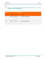
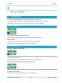
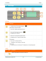
U User Manual Slim Master 01-02-13 English Codice Manuale | Manual Code 000243-SLM124.uso.EN.02-TRI.CSC User Manual | English I Index - Chapter I Index - Chapter .................................................................................................................................................... 2 I Index - Revision Notes ........................................................................................................................................ 4 1 Introduction ......................................................................................................................................................... 5 2 Warnings ............................................................................................................................................................. 6 3 Characteristics .................................................................................................................................................... 7 3.1 GENERAL DESCRITION ......................................................................................................................... 7 4 Operative Mode ................................................................................................................................................... 8 4.1 WEIGHING MODES ................................................................................................................................ 8 4.1.1 Static Weighing............................................................................................................................. 8 4.1.2 Dynamic Weighing........................................................................................................................ 8 4.2 SLIM PANNEL ......................................................................................................................................... 9 4.3 OPERATIVE PAGE................................................................................................................................ 11 4.3.1 Total and Partial Weight ............................................................................................................. 12 4.3.2 Traffic Light................................................................................................................................. 13 4.3.3 User Menu .................................................................................................................................. 14 4.4 WEIGHING PROCEDURE ..................................................................................................................... 17 4.4.1 Weighing on/off........................................................................................................................... 18 4.5 PRINTER (OPTIONAL) .......................................................................................................................... 19 4.6 WEIGHING SETUP................................................................................................................................ 20 4.6.1 Tare Setting ................................................................................................................................ 20 4.6.2 Max Load Setting........................................................................................................................ 22 4.6.3 Max Load Bucket Setting ............................................................................................................ 23 000243-SLM124.uso.EN.02-TRI I2I Index - Chapter User Manual | English 4.6.4 Machine calibration Selection .................................................................................................... 24 4.6.5 Correction Setting ...................................................................................................................... 25 4.6.6 Buzzer Setting............................................................................................................................ 26 4.7 SYSTEM SETUP ................................................................................................................................... 27 4.7.1 Language Setting ....................................................................................................................... 27 4.7.2 Time Setting ............................................................................................................................... 28 4.8 SET VALUE ........................................................................................................................................... 29 5 Diagnostic ......................................................................................................................................................... 30 5.1 ENTER DIAGNOSTIC ........................................................................................................................... 30 5.2 DIAGNOSTIC MENU ............................................................................................................................. 31 5.2.1 Proximity Inputs ......................................................................................................................... 31 5.2.2 On-Off Outputs ........................................................................................................................... 31 5.2.3 Pressure and Angle Sensors ..................................................................................................... 32 000243-SLM124.uso.EN.02-TRI I3I Index - Chapter User Manual | English I Index - Revision Notes Index Rev. Date Sw compatibility Notes 00 30/10/2011 WS06_11 First issue 01 20/11/2012 WS06_12 Norwegian language update 02 01/01/13 WS06_12 Updated contact information 000243-SLM124.uso.EN.02-TRI I4I 1 | Introduction User Manual | Slim Master 01-02-04 English 1 Introduction The information on this document could be subject to change without notice. The constructor is not responsible for possible content mistakes or misprints that could be present in this manual. Any reproduction, translation or copy of parts of this manual is forbidden without prior written authorization by the constructor. WARNING: Modifications not expressly approved by COBO Division 3B6 cause the loss of authorization to operate the system. WARNING: Before starting operations, the user should read and understand this manual and follow the contained instructions. 000243-SLM124.uso.EN.02-TRI I5I 1 | Introduction User Manual | Slim Master 01-02-04 English 2 Warnings 1.1 Use of the System The following directions should enable the person responsible for the system, and the person who actually uses the instrument, to anticipate and avoid operational hazards. The person responsible for the instrument must ensure that all users understand these directions and adhere to them. All users must follow the safety instructions given by the manufacturer and the directions of the person responsible for the instrument. Prohibited uses Using the system without instruction Using outside the stated limits Opening of the equipment by using tools (screwdrivers etc.) Carrying out modification or conversion of the product Use of accessories from other manufacturers without the express approval of COBO Divisione 3B6 Inadequate safeguards at the surveying site (e.g. when measuring on roads, power lines) WARNING: The chance of injury, malfunctions and damage to the equipment if not used as specified. The owner has to inform the user of the hazards in use, protective and counter measures to take. 1.2 Areas of Responsibility WARNING: The person responsible for the instrument must ensure that the equipment is used in accordance with the instructions. This person is also accountable for the deployment of personnel and for their training and for the safety of the equipment when in use The Person in charge of the instrument has the following duties: To understand the safety instructions on the product and the instructions in the User Manual. To be familiar with local safety regulations relating to accident prevention. To inform COBO Divisione 3B6 immediately if the equipment becomes unsafe. 1.3 Checks the user must perform To ensure continuous & safe operations of the system the following checks must be performed regularly by the user. Cable integrity and connectors tightening Angle Sensors integrity and tightening Failure messages showing by display 000243-SLM124.uso.EN.02-TRI I6I 2 | Warnings User Manual | English 3 Characteristics 3.1 GENERAL DESCRITION Description The SLIM-MASTER is a weighing system suitable for forklifts, front loaders and telescopic handlers. System functions The main function and the features are the following: Weighing management in 4 different modes depending on the machine’s application: - Static continuous weighing with cumulative total of any added weight to the initial load (activated by external button); - Static weighing with inputs to calculate the lifted load (activated by a single proximity sensor or keypad); - Dynamic weighing for forklifts (activated by proximity sensors); - Dynamic weighing for front loaders and telescopic handlers (activated by proximity sensors or angular sensors) Temporary disablement of the weighing function Tare function Functions of Total, Partial and Tare Zeroing Maximum load function Partial X2 function Diagnostic function to facilitate troubleshooting in case of system’s malfunction Ability to perform two independent calibrations with different lifting devices applied to the machine (e.g.: forks or bucket) System characteristics Graphic display Visualizing total load, partial load, individuals load of materials in Kg/Lbs and %. Visualizing maximum load with warning lamps: “Traffic Lights”. Optional printer Pre-cabled connections and harness for fast and easy installations. 000243-SLM124.uso.EN.02-TRI I7I 3 | Characteristics User Manual | English 4 Operative Mode 4.1 WEIGHING MODES Use the Slim like a weighing system with all functions according to the active mode. The Weighing Mode is set by the installer and is indicates by the weighing symbol on the display. The Weighing procedure is described following (Refer to “Weighing Procedure” paragraph). 4.1.1 Static Weighing 987.65 12.34 Static without INPUT The partial load is automatically calculated every 5 sec. The total load is calculated by keypad consent (the partial load is added to the total) Static with INPUT The partial load is calculated by external button consent or single proximity The total weight is automatically calculated at the end of the partial load 4.1.2 Dynamic Weighing Dynamic on forklifts (with 2 proximities) 987.65 12.34 The calculating of the partial load automatically begins when the 1st proximity is activated and will be completed when the 2nd proximity is then activated. The total weight is automatically calculated at the end of the partial load calculating Dynamic on front loaders (with 2 proximities or angle sensors) 987.65 12.34 The calculating of the partial load automatically begins when the 1st proximity is activated and will be completed when the 2nd proximity is then activated. The total weight is automatically calculated at the end of the partial load 000243-SLM124.uso.EN.02-TRI I8I 4 | Operative Mode User Manual | 4.2 English SLIM PANNEL L1 L2 L3 1 2 3 BUTTONS Key Description Press&hold (3 sec):Total weigh zeroing key ( ) Static Weighing mode without INPUT Press once: it adds the partial load to the total. Press once: Partial weigh zeroing key ( ) Press&hold (3 sec): Partial x 2 Press once: To print the ticket. (Optional printer) Press&hold (3 sec): To enter the Operation menu In Tare setting: Press once: To memorize new Tare Press&hold (3 sec): Zeroing the Tare value Inside a menu: Press&hold (3 sec): to exit the menus. The display turns on the operating screen. LIGHTS Ref. L1 Lights Description Led L1 lit (ON) indicates Tare value is other than zero. 000243-SLM124.uso.EN.02-TRI I9I 4 | Operative Mode User Manual | Ref. Lights English Description L2 Led L2 lit (ON) indicates Tare value equals zero. L3 “Traffic Lights” Warning lamps for max total load and max partial load in weighing (refer to “Traffic Lights Function” paragraph). DISPLAY Ref. Display symbol Description 1 LCD display At Start up Software version: Release (WS06_XX) / Date (dd/mm/yy) In Operative Mode: Operative Page Operative Menu USER MENU Tare 0.1 2 Total Weight Symbol 3 Single Weight Symbol 000243-SLM124.uso.EN.02-TRI I 10 I 4 | Operative Mode User Manual | 4.3 English OPERATIVE PAGE The Start Up page is displayed for a few seconds at power on. Then the screen shows the operative page ready to work. In the operative page is displayed the weighing mode active, the last bucket weighed and the total of the buckets weighed performed. 1 987.65 12.34 2 3 Ref. Display Icon Description 1 Total Weight: total load of the buckets 2 Single Weighing: load of the last bucket 3 Symbol of active weighing mode (the weighing mode is set by Installer): : Static Weighing Mode and Dynamic Weighing Mode on forklifts : Dynamic Weighing Mode on front loader 000243-SLM124.uso.EN.02-TRI I 11 I 4 | Operative Mode User Manual | English 4.3.1 Total and Partial Weight 987.65 TOTAL WEIGHT 12.34 PARTIAL WEIGHING Total Weight: Total load of the buckets Total Zeroing Zeroing the total weight an occurred warning of maximum load (through traffic lights) will be stopped. Press&hold (3 sec) the key to perform the Total zeroing Partial Weight: Load of the last bucket Partial Zeroing Deleting the last bucket weighed the partial weigh will be removed to the total weight. To be used if the bucket has been wrong or accidentally weighed and the material will not be putted on the truck. Press once the key to perform the Partial zeroing Partial x 2 (Residue material function) This function removes twice the last value weighed from the total. When the last bucket load did not empty completely proceed as following: Perform a weighing of the material which has remained in the bucket to find out the effective quantity unloaded Press&hold (3 sec) the 000243-SLM124.uso.EN.02-TRI key. to perform the Partial x 2. The calculated total meets that actually loaded. I 12 I 4 | Operative Mode User Manual | English 4.3.2 Traffic Light TRAFFIC LIGHTS 987.65 12.34 Max Load The 3 LEDs on the SLIM-MASTER (as shown above) will light up according to the percentage of the Total Load lifted in relation to the Maximum Load set, by following the criteria set below: RED LED lit when the Total Weight equals or exceeds 100% of the Max Load set YELLOW LED lit when the Total Weight is between 90% and 99% of the Max Load set GREEN LED lit when the Total Weight is between 0% and 89% of the Max Load set. Upon exceeding the maximum load set for first time (refer to “Max Load” paragraph), additional to the red led, the SLIMMASTER will emit 3 beeps in rapid succession. This audio warning will be repeated every weighing cycle with the Total Weight greater than the Max Load set, until the Total Weight will be zeroed. To set the max load refer to the “Max Load Setting” paragraph. Max Load Bucket The 3 LEDs on the SLIM-MASTER (as shown above) will light up according to the percentage of the Partial Load lifted in relation to the Maximum Load Bucket set, by following the criteria set below: RED LED lit when the Partial Weight equals or exceeds 100% of the Max Load Bucket set YELLOW LED lit when the Partial Weight is between 90% and 99% of the Max Load Bucket set GREEN LED lit when the Partial Weight is between 0% and 89% of the Max Load Bucket set. Upon exceeding the maximum load of bucket set for first time (refer to “Max Load Bucket” paragraph), additional to the red led, the SLIM-MASTER will emit 3 beeps in rapid succession. This audio warning will be repeated every weighing cycle with the Partial Weight greater than the Maximum Load Bucket set, until the partial weight does not fall below the maximum load of bucket. To set the max load refer to the “Max Load Bucket Setting” paragraph. 000243-SLM124.uso.EN.02-TRI I 13 I 4 | Operative Mode User Manual | English 4.3.3 User Menu The User Menu is the main operating menu. To enter the User Menu press&hold for 3 seconds the key from the operative screen. 987.65 12.34 3 sec USER MENU Tare Key / Ref. 1 XX 2 Description To scroll the menu list To accede sub-menus or enable/disable commands (ON/OFF). Press&hold (3 sec): exit from the menu. The display turns on the operating screen. 1 1st line: Menu Header 2 2nd line: Menu List 000243-SLM124.uso.EN.02-TRI I 14 I 4 | Operative Mode User Manual | English Menu List Display Type Description Weighing Setup Tare: xxx Visualize Last Tare value memorized Weighing Procedure Weighing: OFF Command Temporary disabling of weighing system (ON/OFF) Weighing Setup Max Load: xxx.x Setting Maximum Total Load for traffic lights function. Weighing Setup Max Load B:xxx.x Setting Maximum Bucket Load for traffic lights function. Weighing Setup Machine: x Command Selection of the machine calibration (1/2) Not available if regenerative valve present Weighing Setup Correction: xxx Setting Correction in percentage of single weighing (Range: 90÷110) Weighing Setup ( Buzzer OFF Command Buzzer state selection during weighing (ON/OFF) Only in Static Weighing Mode System Setup Contrast xxx Setting Display contrast System Setup Language: UK Command Selection of the display language (e.g.. UK) System Setup Time Setting Sub-menu Access to time setting menu System Check (Diagnostics) Sensor Check Sub-menu Access to sensors check menu Calibration Setting Menu Sub-menu Access to setting menu (reserved to installer) Refer to the Calibration Manual 000243-SLM124.uso.EN.02-TRI I 15 I 4 | Operative Mode User Manual | English Type: Visualize: to view a set or memorized value. Setting: this description refers to any value that can be modified, in which case follow the procedure described in the paragraph “Set value”. Command: enables directly a function. Sub-menu: allows access to a sub-menu. 000243-SLM124.uso.EN.02-TRI I 16 I 4 | Operative Mode User Manual | 4.4 English WEIGHING PROCEDURE Weighing must be performed according to the active Weighing Mode. Static weighing without INPUT (“continuous”) (weighing mode symbol: ) Place the machine in the weighing position. The SLIM-MASTER will calculate and update the partial load automatically every 5 sec. The partial load will be added to the total load by pressing once the Static weighing “with INPUT” (weighing mode symbol: key. ) With manually activated external push button Place the machine in the weighing position. Press the external push button. The SLIM-MASTER will calculate the partial load, and at the end it will be added automatically to the total weight. The buzzer (if enabled) will sound continuously during the calculation process. With single proximity installed Lift the load until the proximity is activated (the correct position will be signaled by the buzzer in the SLIM). Stop lifting immediately, and wait until the buzzer stops. At this point the SLIM-MASTER will update the partial weight, and it will be added automatically to the total weight. Dynamic weighing on forklifts with 2 proximities (weighing mode symbol: ) Following the initial lift off the ground, maintain a constant lifting speed during the complete weighing cycle. The SLIM-MASTER will begin calculating the load automatically when the 1 st proximity is activated, and will be completed when the 2nd proximity is then activated. The buzzer will start beeping when the 1st proximity is activated, and will continue until the completion of the weighing cycle. The partial load will then be added automatically to the total weight. Dynamic weighing on front loaders with 2 proximities (or angle sensors) (weighing mode symbol: ) Having filled the bucket, begin lifting maintaining a constant lifting speed during the complete weighing cycle. The SLIM-MASTER will begin calculating the load automatically when the 1 st proximity is activated, and will be completed when the 2nd proximity is then activated. The buzzer will start beeping when the 1st proximity is activated, and will continue until the completion of the weighing cycle. The partial load will then be added automatically to the total weight. IMPORTANT: Avoid weighing with the machine tilted sideways, and/or sloping forward or backward; also avoid sudden and/or abrupt movements during the weighing operation. 000243-SLM124.uso.EN.02-TRI I 17 I 4 | Operative Mode User Manual | English 4.4.1 Weighing on/off In case the machine may be required for alternative tasks whilst engaged in loading/weighing operations, and it is necessary to retain the value of load accumulated till then, it is possible to interrupt the operation, by temporarily disabling the weighing cycle, and resume the operations later to complete the loading of that particular truck. Enable/disable Weighing From the operating screen to keep pressed the Scroll the Mix Menu with Press , key to enter the User Menu. keys and select the command “Weighing”. key to enable/disable the function ON: Weighing enable USER MENU Weighing: ON USER MENU Weighing: OFF OFF: Weighing disable With weighing disabled the “Traffic Lights” lamps is off. Exiting from the command, the weighing function is automatically enabled. Press&hold (3 sec) 000243-SLM124.uso.EN.02-TRI key to go back to the operative page. I 18 I 4 | Operative Mode User Manual | 4.5 English PRINTER (OPTIONAL) To be able to print it is necessary to press once the key when the machine is in the operating screen. 987.65 12.34 The printed ticket will show the following details: # Date Time 000000025 09/12/2005 Progressive number of printed tickets Date and time of print 17:43 Total Total Weight 987.65 Kg Note: The unit of measure referred to on the ticket is set during the calibration of the SLIM-MASTER. 000243-SLM124.uso.EN.02-TRI I 19 I 4 | Operative Mode User Manual | 4.6 English WEIGHING SETUP 4.6.1 Tare Setting Setting a new tare function may be necessary when the machine is cold, changing the current bucket, changing hydraulic oil in the circuit, or when some material accumulates in the bucket, which cannot be dislodged during normal dumping operation. By setting a new tare, it enables zeroing the extra weight of the bucket, thus weighing only the material effectively dumped. It is advisable to verify the status of the tare prior the beginning loading operation, by performing a empty weigh; in the eventuality that the partial weigh is not “0” perform the tare acquiring. Repeat this operation a few times during the day to compensate the hydraulic oil temperature variation. Visualization of the actual tare From the operating screen to keep pressed the Scroll the User Menu with , key to enter the User Menu keys and select the line “Tare”: the tare value is displayed. “L1”led ON with Tare ≠ 0 USER MENU Tare: 1.12 “L2” led ON with Tare =0 USER MENU Tare: 000243-SLM124.uso.EN.02-TRI I 20 I 0.00 4 | Operative Mode User Manual | English Zeroing existing Tare It’s possible delete the actual tare (for example before a new acquiring). Whilst holding aloft the empty bucket, press&hold the key until the lower led (L2) is lit: At this point the Tare value will be zeroed. Acquiring NewTare If a tare value is yet present “L1” led on , proceed to delete the actual value bofore new acquiring (Zeroing existing Tare). Perform an empty weighing based on the active weighing mode shown on the SLIM screen. The screen will display a value for the partial weight (e.g. 2.32) to set as new tare. 0.00 2.32 0.00 2.32 Press once the key. The upper led (L1) will light up: The new value will be acquired. 000243-SLM124.uso.EN.02-TRI I 21 I 4 | Operative Mode User Manual | English 4.6.2 Max Load Setting The Max Load setting allows to set a maximum threshold of load for the “Traffic Lights” indication. USER MENU Max Load: 40.50 Setting of the Max Load From the operating screen to keep pressed the Scroll the User Menu with Press , key to enter the User Menu keys and select the line “Max Load”. The actual value is displayed. key to enter the new setting. Set the value of the Max Load (look to paragraph “Set value”). Press&hold (3 sec) 000243-SLM124.uso.EN.02-TRI key to go back to the operative page. I 22 I 4 | Operative Mode User Manual | English 4.6.3 Max Load Bucket Setting The Max Load Bucket setting allows to set a maximum threshold of bucket load for the “Traffic Lights” indication. USER MENU Max Load B:40.50 Setting of the Max Load Bucket From the operating screen to keep pressed the Scroll the User Menu with Press , key to enter the User Menu keys and select the line “Max Load B”. The actual value is displayed. key to enter the new setting. Set the value of the Max Load B (look to paragraph “Set value”). Press&hold (3 sec) 000243-SLM124.uso.EN.02-TRI key to go back to the operative page. I 23 I 4 | Operative Mode User Manual | English 4.6.4 Machine calibration Selection The Machine function allowed to select the desired calibration mode typically used when the machine is equipped with 2 different lifting devices (e.g. Bucket / Forks). Note: This selection is not possible if the regenerative valve management is enable (refer to the Calibration Manual). Selection of the machine (machine calibration) From the operating screen to keep pressed the Scroll the User Menu with , key to enter the User Menu. keys and select the command “Machine”. The actual value is displayed. Press once key to active the machine calibration (1/2). “1” : Machine1 active USER MENU Machine: 1 USER MENU Machine: 2 “2” : Machine2 active Press&hold (3 sec) 000243-SLM124.uso.EN.02-TRI key to go back to the operative page. I 24 I 4 | Operative Mode User Manual | English 4.6.5 Correction Setting The “Correction” function is used to override persisting minor errors in each weighing cycle. USER MENU: Correction 103 It is possible to set a factor of ±10% in relation to the calibration value: 100 = no correction factor is evident. 110 = the maximum positive correction to increase the weighed load. 90 = the maximum negative correction factor to decrease the weighed load. Set the correction From the Operating screen to keep pressed the Scroll the menu with Press e key to enter the User Menu. keys and select the “Correction” setting key to enter the function. Set or modify the value of the correction (look to paragraph “Set value”). Press&hold (3 sec) 000243-SLM124.uso.EN.02-TRI key to go back to the operative page. I 25 I 4 | Operative Mode User Manual | English 4.6.6 Buzzer Setting The “Buzzer” function is used to set the status of the buzzer (continuous or silent sound) during the weight calculation process in the Static Weighing Mode. This function is settable only in Static Weighing Mode. Enable/disable Buzzer From the operating screen to keep pressed the Scroll the menu with Press , key to enter the User Menu. keys and select the command “Buzzer”. key to enable/disable the function ON: Buzzer active USER MENU Buzzer: ON USER MENU Buzzer: OFF OFF: Buzzer silent Press&hold (3 sec) 000243-SLM124.uso.EN.02-TRI key to go back to the operative page. I 26 I 4 | Operative Mode User Manual | 4.7 English SYSTEM SETUP 4.7.1 Language Setting It is possible to select the language of the menus. From the operating screen to keep pressed the Scroll the menu with , key to enter the User Menu. keys and select the command “Language”. The screen shows the language in use. In the “language” command, press key until the language to use in is set. USER MENU: Language: Press EN to go back to operative page. The selection is automatically setted. Language List: IT = Italian UK = English ES = Spanish FR = French TR = Turkish FM = Flemish PT = Portuguese GE = German DK = Danish NW = Norwegian 000243-SLM124.uso.EN.02-TRI I 27 I 4 | Operative Mode User Manual | English 4.7.2 Time Setting To modify the Time and Date. From the operative screen to keep pressed the key to enter the User Menù. USER MENU: Time Setting Display Type USER MENU Time setting HEADING menu Description Select the “time setting” menu with , and confirm with Time setting Menu TIME SETTING minute: X HEADING setting hour: X setting day: X setting month: X setting year: X setting Use the , keys to scroll the lines and to enter the value (to set the value look the paragraph “Set value”). TIME SETTING update time… HEADING command Select the line and press ENTER to confirm command Press again time update! visualize The system displays this message to confirm the to confirm the setting. to save the setting. modifications. 000243-SLM124.uso.EN.02-TRI I 28 I 4 | Operative Mode User Manual | 4.8 English SET VALUE Set a new value, for example Max Load. USER MENU Max Load: Display USER MENU Max Laod: 0.00 Description With keys select the function to set (e.g. “Max Load”) and press , 0.00 to enter the setting. Max Laod: 0.00 Press the The asterisk displayed shows the digit to be modified. Use Max Laod: * 0.00 Max Laod: * 1.00 1.00 key to scroll the asterisk above the digit to change. Use the Press Max Laod: key to enable the setting. , keys to modify (increase/decrease) the value of the digit. key to confirm the changes. The asterisk disappears. Press&hold 000243-SLM124.uso.EN.02-TRI to exit the setting. I 29 I 4 | Operative Mode User Manual | English 5 Diagnostic The diagnostic allows viewing the status of all inputs and outputs of the Slim. 5.1 ENTER DIAGNOSTIC From the operating screen to keep pressed the Scroll the menu with diagnostic menu. , key to enter the User Menu. keys and select the function “Sensor check” and press to enter the USER MENU Sensor Check SENSOR CHECK Proximity Key / Ref. 1 2 Description To scroll the menu list To accede sub-menus or enable/disable commands (ON/OFF). Press&hold (3 sec): exit from the menu. The display turns on the operating screen. 1 1st line: Menu Header 2 2nd line: Menu List 000243-SLM124.uso.EN.02-TRI I 30 I 5 | Diagnostic User Manual | 5.2 English DIAGNOSTIC MENU Display Type Description SENSOR CHECK HEADING Use the , keys to scroll the sub-menu. Proximity sub-menu To accede the sub-menu, by pressing the Proximity sub-menu Access to proximity menu on-off outputs sub-menu Access to on-off outputs menu pressure sensors sub-menu Access to pressure sensors menu key. 5.2.1 Proximity Inputs This menu visualizes the status of the proximity switches. The proximity status is normally OFF. During the weighing cycle, when they become active, the status is ON. Display Type INPUT STATUS proxy.1 OFF HEADING proxy.2 OFF Description visualize Status of the Proximity 1 Input visualize Status of the Proximity 2 Input Use the , keys to scroll the data. 5.2.2 On-Off Outputs This menu visualizes the status of the digital outputs. Display Type OUTPUT STATUS Buzzer OFF Output 4 OFF HEADING visualize visualize Description Status of the Slim internal buzzer (ON=active) Printer power supply status (ON=active) Use the 000243-SLM124.uso.EN.02-TRI I 31 I , keys to scroll the data. 5 | Diagnostic User Manual | English 5.2.3 Pressure and Angle Sensors This menu visualizes the status of transducers and angle sensors. Menu Text Type Description ANALOGUE VALUE Press.Low XXXX HEADING visualize Piston side transducer output value Press.High XXXX visualize Rod side transducer output value Boom Ang1 XXXX visualize Boom angle sensor (machine 1) Chassy Ang1 XXXX visualize Chassis angle sensor (machine 1) Boom Ang2 XXXX visualize Boom angle sensor (machine 2) Chassy Ang2 XXXX visualize Boom angle sensor (machine 2) Use the 000243-SLM124.uso.EN.02-TRI I 32 I , keys to scroll the data. 5 | Diagnostic