1
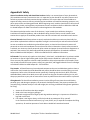
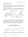
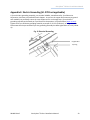
QIMS.E339731 Grizzly Bear FR Gen II QIMS2.E339731 Module Mounting Attachment Grizzly Bear® FR Gen II Installation Manual Grizzly Bear® FR Gen II Installation Manual Table of Contents Introduction .......................................................................................................................................... 3 Parts List ................................................................................................................................................ 4 Installation ............................................................................................................................................ 5 Step 1. Mark Array Perimeter .................................................................................................... 5 Step 2. Lay Out Supports ............................................................................................................ 5 Step 3. Attach Claws to Module ................................................................................................. 6 Step 4. Mount Modules to Supports .......................................................................................... 7 Step 5. Electrical Grounding ....................................................................................................... 9 Step 6. Install Wind Deflectors ................................................................................................. 10 Technical Support ............................................................................................................................... 12 Appendix A: Alternate Claw Attachment to Module .......................................................................... 13 Appendix B: Safety .............................................................................................................................. 18 Appendix C: Spacer Sticks ................................................................................................................... 20 Appendix D: South Support................................................................................................................. 21 Appendix E: Electric Grounding (UL 2703 not applicable) .................................................................. 23 9910010 Rev F Grizzly Bear® FR Gen II Installation Manual 2 Grizzly Bear® FR Gen II Installation Manual Introduction Grizzly Bear® FR Gen II is designed to maximize array construction speed and minimize construction risk. Grizzly Bear’s patent pending, innovative, streamlined construction features: Just three major components plus two nut and bolt sizes Several labor saving factory-installed features A modular, adaptable design with a single-module tilt-up feature The Grizzly Bear system has been extensively tested, undergoing individual component finite element analysis, computational fluid dynamics modeling, static load modeling, and wind tunnel testing. All testing has been independently conducted by third parties and provided to PanelClaw, Inc. (“PanelClaw”). PRIOR TO COMMENCING THE INSTALLATION OF THE GRIZZLY BEAR® FR GEN II PHOTOVOLTAIC MOUNTING SYSTEM, IT IS IMPERATIVE THAT YOU FIRST READ THE SAFETY PROVISIONS ATTACHED ON Appendix B HERETO. 9910010 Rev F Grizzly Bear® FR Gen II Installation Manual 3 Grizzly Bear® FR Gen II Installation Manual Parts List This is a parts list for a basic Grizzly Bear FR Gen II installation not requiring Roof Connector Assembly. Please refer to the PanelClaw Roof Connector Installation Manual, available at www.panelclaw.com, for instructions on mechanical attachment of the system. Support* Standard Claw Fastener Kit Wind Deflector Wind Deflector End Plate Claw (1) Pre-installed hex head cap screw 3/8-16 x 1.0“ Stainless Steel 18-8 (Please see Appendix A for Multi-piece and Long Claw information) Support (1) Ballasted flange Support unit * The system is also available with optional South Supports, which can be used as an alternative to fullsized Supports in all south-facing array edges. Please see Appendix D for more information. Fastener Kit (2) Hex head cap screws 3/8-16 x 1.25” Stainless Steel 18-8 (304) (2) Serrated flange nuts 1/4-20 Stainless Steel 18-8 (304) (2) Serrated flange nuts 3/8-16 Stainless Steel 18-8 (304) Wind Deflector (1) Slotted wind deflector (1) Wind deflector end plate Tools required for installation: 7/16” Wrench or socket 9/16” Wrench or socket 9910010 Rev F Grizzly Bear® FR Gen II Installation Manual 4 Grizzly Bear® FR Gen II Installation Manual Installation Grizzly Bear® FR Gen II can be installed in 6 easy steps. Step 1. Mark Array Perimeter Mark the array perimeter using a chalk line or similar method. See site’s Ballast Layout Drawing provided by PanelClaw for array dimensions. Step 2. Lay Out Supports Deploy the Supports along the marked array perimeter. Note: The system is also available with optional South Supports, which can be used as an alternative to full-sized Supports in all south-facing array edges. Please see Appendix D for more information. 1. To assist in proper row and module spacing, PanelClaw makes Spacer Sticks available. These tools are easily employed to ensure module Supports are properly spaced in the array. To assemble the Spacer Sticks please follow the directions below. Slots East-West Spacer Stick To set the Spacer Sticks to the correct length, remove the hardware from each Spacer Stick. Then reference the Ballast Layout Drawing to determine proper stick length. The “Project Details” section of the Ballast Layout will contain lengths for both the longer, slotted East-West and shorter North-South Spacer Stick with PEM® studs. The lengths indicated in the Ballast Layout reflect the length between the two slots on the East-West spacer stick and between the center of each of the two PEM studs on the North-South Spacer Stick. Set the spacer sticks to the correct length and then replace and tighten the hardware to secure the Spacer Sticks in position. The Spacer Stick lengths can also be established by using the procedure found in Appendix C. North-South Spacer Stick 3/8” Studs The Spacer Sticks are now ready for use to set Support spacing and attach PV modules. 2. Pick a starting corner on the North end of the array and place four (4) Supports as shown below (Fig. 1), each Support should be laid out with the high end to the South and the low end to the North. 9910010 Rev F Grizzly Bear® FR Gen II Installation Manual 5 Grizzly Bear® FR Gen II Installation Manual PanelClaw recommends starting the array in a corner with low complexity and moving outwards in a direction that best suits the individual array you are building (e.g. rows and columns with the least number of interruptions/breaks). Use the properly configured East/West Spacer Stick (the longer stick) to position the Supports. Place the notch in the East/West Spacer over the low end of the Support at the edge of the array and position the Support directly to the East or West (depending on build direction) so that the notch at the other end of the Spacer Stick fits over the low end of the adjacent Support. The distance to the Support to the South can be established using the North/South Spacer Sticks. In this case the 3/8” studs in the Spacer Stick are placed in the proper Claw mounting hole of the high end of the Support at the edge of the array and used to position the Support directly South by placing the 3/8” stud at the other end of the Spacer Stick in the hole at the low end of the Support to the South (Fig. 1). This process can be continued to layout the remainder of the array. Grizzly Bear® FR Gen II is equipped with multiple mounting holes to allow for different row spacing options and to address wavy roofs. To determine the proper Claw mounting holes to use with the Spacer Stick on the high and low end of the Support for this array, please refer to the Ballast Drawing. Fig. 1 Array Layout South North-South Spacer Stick East-West Spacer Stick Step 3. Attach Claws to Module PanelClaw offers three Claw options to accommodate different frame types, Standard (Claw I), Multipiece (Claw III), and Long (Longitudinal). The following directions are for the Standard Claw (Claw I), for Multi-piece and Long Claw mounting instructions please see Appendix A. Place a PV module face down on a protected work surface and place a Claw over the module frame flange on the short side of the module; slide to the corner and tighten the 3/8-16 x 1.0” 18-8 hex head cap screw between 18 and 20 ft-lb (24.4-27.1 N-m). Ensure that the Claw is seated up against the flanges of both the long and short sides of the module as shown in Fig. 2 below. Each module must be fitted with four (4) Claws. The module is now ready to be attached to the Supports. 9910010 Rev F Grizzly Bear® FR Gen II Installation Manual 6 Grizzly Bear® FR Gen II Installation Manual At this point, it is a good time to prepare the module cables for connection per the module manufacturer’s specifications and install the module grounding mechanism (not included) per the module manufacturer’s specifications if necessary (see Step 5. Electrical Grounding, to determine array grounding requirements). Fig. 2 Claw Attachment Step 4. Mount Modules to Supports Begin attaching modules to Supports moving from West to East (or East to West) starting at the Southwestern (or Southeastern) most corner of the array and moving North as each row is completed. For the steps below, assume the Southwestern most corner is the starting point. 1) Attach the module to the inside of the low end of the first two North facing Supports, by inserting a 3/8-16 x 1.25” 18-8 hex head cap bolt through the hole in the Claw and the hole labeled “A” on the Support. NOTE: Low-end hole marked ‘B’ is NOT an approved Claw mounting hole for Grizzly Bear. Ensure that the hex cap bolts are inserted into the Support mounting holes so the threaded end of each hex cap bolt faces the next Support to be installed (to the East). A 3/8-16 serrated flange nut should then be finger tightened on the Western-most Support only to initially secure the module (Fig. 3). Fig. 3 Attach Module to North Support Serrated Flange 3/8-16 Hex Nut 3/8-16 x 1.25 Hex Head Cap Screw 9910010 Rev F Grizzly Bear® FR Gen II Installation Manual 7 Grizzly Bear® FR Gen II Installation Manual 2) Tilt the module back and attach the Claws to the high end of the North Support by inserting a 3/8-16 x 1.25” 18-8 hex head cap bolt through the hole in the Claw and the Support. Please refer to the Ballast Layout Drawing for the proper hole choice, “2” (default) or “4” (reduced row spacing) on the high end of the Support. Ensure that the hex cap bolts are inserted into the Support mounting holes so the threaded end of each hex cap bolt faces the next Support to be installed (to the East) (Fig 4). Fig. 4 Tilt Module to Attach to North Support Claw North Support PV Module High End Fig. 5 Default Mounting Hole 3/8-16 Serrated Flange Hex Nut Default Mounting Hole (Marked ‘2’) 3/8-16 x 1.25 Hex Head Cap Screw 3) Secure Western-most Claws to Supports using the 3/8-16 serrated flange nuts. The recommended minimum torque is 30 ft-lb (40.7 N-m). 4) Continue building the array from West to East (or East to West) by bringing the next module into place. a) The bolts on the Northwest and Southwest sides of the array are already in place from the prior module mounting. b) Add bolts to the Northeast and Southeast sides. c) Secure the Western-most Claws only to Supports using the 3/8-16 serrated flange nuts. d) Connect the module to module wiring. Repeat this process until all modules are mounted. 9910010 Rev F Grizzly Bear® FR Gen II Installation Manual 8 Grizzly Bear® FR Gen II Installation Manual Step 5. Electrical Grounding Please consult with national and local building code(s) for complete grounding requirements for your installation. The Grizzly Bear mounting system is UL and ETL listed to UL 2703 (Rack Mounting Systems and Clamping Devices for Flat-plate Photovoltaic Modules and Panels). Grizzly Bear mounting systems enable installers using modules included in PanelClaw’s UL 2703 listings to quickly and easily establish UL/ETL-certified electric bonds between all connected array components, including modules and mounting system components, without the use of additional grounding devices, e.g. ground lugs and copper wire. Multiple strings with a combined fuse rating of up to 125 amps can be grounded via a single ground lug acting as a Grounding Electrode Conductor (GEC). When grounding devices are installed according with the approved methodology and capacity below, the connections described above meet all the requirements outlined in NEC 690.43. All PanelClaw module mounting attachments (“Claws”) are certified as recognized components under UL 2703 for module-to-module and module-to-mounting system electric bonding. For projects using modules not currently included in PanelClaw’s UL 2703 listings, additional approvals from the module manufacturer and the relevant permitting authority may be necessary to utilize the UL 2703 electric bonding and grounding method below. Additional information regarding UL 2703 and the specific modules included in PanelClaw’s UL and ETL listings can be found in the PanelClaw UL & ETL Overview (UL 2703) document (available at www.panelclaw.com). For modules that are listed, please follow the instructions. For unlisted and unapproved modules follow the grounding instructions below in Appendix E. Grounding Instructions (UL 2703 Compliant) Supports within the array are required to be electrically bonded to other DC grounding paths via the use of either #8 or #6 AWG Cu bonding jumpers and a compatible UL 467 listed grounding device acting as a GEC. To ground the array, first determine the quantity of strings that a single bonding jumper connection can accommodate based on the module series fuse rating and bonding jumper size, (Table 1). Note: Verify that all devices used in connecting this bonding jumper can accommodate the conductor being used. Table 1 Strings per Bonding Jumper Module Series Fuse Rating / DC String Fuse Rating (A) 10 15 20 25 30 Size of Bare Cu Bonding Jumper (AWG) #8 #6 Allowable Ampacity of Conductor (A) 90 125 Number of Strings per Bonding Jumper 9 12 6 8 4 6 3 5 3 4 Once the quantity of strings per bonding jumper has been determined, a UL 467 listed grounding device must be attached to one Support within that group of strings. PanelClaw provides Supports with a multi-purpose tab to which a grounding device/lug can be attached (Fig. 9). The multi-purpose tab has a 9910010 Rev F Grizzly Bear® FR Gen II Installation Manual 9 Grizzly Bear® FR Gen II Installation Manual hole that is .198” - .208” in diameter. In some cases a grounding device/lug can come pre-installed, in this case, ensure that the pre-installed grounding device/lug is listed to UL 467 and can accommodate the size of conductor being installed. In an array that requires multiple bonding jumpers to satisfy the capacity requirements, each bonding jumper should be located and installed on a Support within the group of strings which will be grounded by that jumper. Note: Every independent array section must include at least one grounding device/lug. Fig. 6 Install Grounding Device to Multi-purpose Tab Multi-purpose Tab To attach a grounding device/lug to the Support tab, please refer to the installation manual for the grounding lug/device. Once a grounding device/lug has been attached to the Support, a copper bonding jumper must be installed as described in the installation manual of the grounding device/lug installed from an acceptable DC grounded location outside of the array. Step 6. Install Wind Deflectors Wind Deflectors mount to the Supports via the Support’s pre-installed PEM studs using two 1/4" – 20 serrated flange nuts per Support (Fig. 7). Wind Deflectors must be installed in a particular order: 1) Start installation with Western-most array column. Place the first Wind Deflector on the Western-most Supports of the first row. Secure the Wind Deflector on the Westernmost Support using two serrated flange nuts, toquing them to 8 ft-lb (10.8 N-m). Make sure PEM studs of the Support directly to the East are fully visible through the Wind Deflector slots (Fig. 7). Note: The Wind Deflector is installed with the PanelClaw logo facing toward you and right side up. 2) Place the second Wind Deflector over the exposed PEM studs of the Support directly to the East (and over the first Wind Deflector) and secure the second Wind Deflector to the Support using two serrated flange nuts, toquing them to 8 ft-lb (10.8 N-m). Ensure that the PEM studs of the Eastern Support on which the Wind Deflector rests are fully visible through the Wind Deflector slot (Fig. 8). 3) Continue installing Wind Deflectors moving East. 9910010 Rev F Grizzly Bear® FR Gen II Installation Manual 10 Grizzly Bear® FR Gen II Installation Manual 4) Each and every row must be terminated on the Eastern-most Support with a Deflector End Plate. Note: For rows with discontinuties, Deflector End Plates must be utilized to secure the Wind Deflector on each Support that does not have a module and Wind Deflector attached on the Eastern side. The Deflector End Plate should be place on the exposed PEM studs (and over the Wind Deflector sitting on the PEM studs) of the Eastern-most Support of every row that requires Wind Deflectors. The Deflector End plate should be secured with two 1/4" – 20 serrated flange nuts torqued to 8 ft-lb (10.8 N-m) (Fig. 9). A Wind Deflector must be installed on the Northside of every module. No Wind Deflectors should be installed on the Southern-most row of Supports (these Supports will only have modules attached at the low end of the Support). At the end of each work day a Wind Deflector must be attached to any Supports to which a module has been mounted with the exception of the Northern-most row of Supports as noted above. Fig. 7 Wind Deflector Installation Western-most Support East South Exposed PEM Studs ¼ 20 Serrated Flange Hex Nuts Wind Deflector Slots 9910010 Rev F Grizzly Bear® FR Gen II Installation Manual 11 Grizzly Bear® FR Gen II Installation Manual Fig. 8 Installation of Second Wind Deflector South ¼ 20 Serrated Flange Hex Nuts East Fig. 9 Securing the Last Wind Deflector in a Row South East ¼ 20 Serrated Flange Hex Nuts Wind Deflector End Plate Technical Support To contact PanelClaw Customer Technical Support, call +1 978.688.4900 or email [email protected]. 9910010 Rev F Grizzly Bear® FR Gen II Installation Manual 12 Grizzly Bear® FR Gen II Installation Manual Appendix A: Alternate Claw Attachment to Module Long Claw (Longitudinal Claw) This Claw is used for PV modules that are not compatible with flange clamp style Claws. The Long Claw attaches at the module mounting holes. Please see the module manufacturer’s installation guide for screw torque specifications. Long Claw Detail: Module Mounting Holes* Module Grounding Holes* (when applicable) Support Mounting Tabs Module Flange Hems Module Drainage Holes* (when applicable) *Hole quantity and locations will vary per module 1) Place a PV module face down on a protected work surface (Fig. 1). Fig. 1 Place Module Face Down Long Side Flange 9910010 Rev F Short Side Flange Grizzly Bear® FR Gen II Installation Manual 13 Grizzly Bear® FR Gen II Installation Manual 2) Orient a Long Claw parallel to the long side of the module. Ensure that the module flange hems are facing down and the support mounting tabs are facing outward. Once oriented, lower the Long Claw until the ends rest on the short side flanges of the module (Fig. 2). Fig. 2 Orient and Lower Long Claw Support Mounting Tabs Out Module Flange Hems Down 3) Continue by sliding the Long Claw toward the long side flange of the module until the hems slide past the module flange and the module mounting holes are aligned (Fig. 3). Fig. 3 Lower Long Claw onto Short Side Flanges 4) Secure the Long Claw with the hardware provided, ensuring that the bolt is inserted from the underside of the flange and facing up (Figs. 4a & 4b). Torque the hardware to the module manufacturer’s specifications. Fig. 4a Install Hardware 9910010 Rev F Grizzly Bear® FR Gen II Installation Manual 14 Grizzly Bear® FR Gen II Installation Manual Fig. 4b Cross Sectional Detail of Installed Long Claw Bolt Nut Long Claw Long Side Flange Top Side of Module 5) Repeat Steps 1 through 4 for the other side of the module (Fig. 5). The module is now ready to be attached to the Supports. At this point, it is a good time to prepare the module cables for connection per the module manufacturer’s specifications and install the module grounding mechanism (not included) per the module manufacturer’s specifications if necessary (see Step 5. Electrical Grounding, to determine array grounding requirements). Fig. 5 Completed Long Claw Installation 9910010 Rev F Grizzly Bear® FR Gen II Installation Manual 15 Grizzly Bear® FR Gen II Installation Manual 6) Attach the module to the inside of the low end of the first two north-facing Supports by inserting a 3/8-16 x 1.25” 18-8 hex head cap screw through the hole in the Claw and the hole labeled “A” on the Support. NOTE: Low-end hole marked ‘B’ is NOT an approved Claw mounting hole for Grizzly Bear. Ensure that the hex head cap screws are inserted into the Support mounting holes so the threaded end of each hex head cap screw faces the next Support to be installed (to the east). A 3/8-16 serrated flange nut should then be finger tightened on the western-most Support only to initially secure the module (Fig. 6 Top). Tilt the module back and attach the Claws to the high end of the North Support by inserting a 3/8-16 x 1.25” 18-8 hex head cap screw through the hole in the Claw and the Support. Please refer to the Ballast Layout Drawing for the proper hole choice, “2” (default) or “4” (reduced row spacing) on the high end of the Support. Holes “1” and “3” are for use with the default “2” hole designation to provide flexibility on wavy roofs. Ensure that the hex head cap screws are inserted into the Support mounting holes so the threaded end of each hex head cap screw faces the next Support to be installed (to the east) (Fig. 6 Bottom). Fig. 6 Module Attachment to Support South 3/8-16 Serrated Flange Nut 3/8-16 x 1.25 Hex Head Cap Screw Default Mounting Hole (Marked “2”) 9910010 Rev F Grizzly Bear® FR Gen II Installation Manual 16 Grizzly Bear® FR Gen II Installation Manual Multi-piece Claw (Claw III) This Claw is used when the PV module specified does not allow short-side PV frame flange mounting. For proper attachment, place a Claw over the module frame flange on the long side of the module; slide to the corner, and tighten the 3/8-16 x 1.25” 18-8 hex head cap screw between 18 and 20 ft-lb (24.4-27.1 N-m). Ensure that the “C” shaped portion of the Claw is seated up against the flange on the long side of the module and that the “L” shaped piece of the Claw is seated over the module frame, with the tab flush against the short side of the module as shown in the image below. Multi-piece Claw Detail: Please contact PanelClaw Customer Technical Support for additional information about alternative Claws. 9910010 Rev F Grizzly Bear® FR Gen II Installation Manual 17 Grizzly Bear® FR Gen II Installation Manual Appendix B: Safety General Installation Safety with PanelClaw Products: Safety is an essential part of every photovoltaic (PV) installation and every construction site. It is imperative to plan ahead for any safety concerns and hazards to promote safe work practices during installation. This section does not claim to address or support all safety concerns that may arise during the installation of PanelClaw mounting systems or any other aspect of the work being performed. Before beginning work, installers should refer to all local and federal safety, health, and regulatory requirements to assure compliance. Refer to OSHA Part 1926 and its related Subparts for federal construction related regulations and standards. The subsections below outline some of the obvious / major hazards that could exist during the installation of PanelClaw products, and are divided to bring a level of clarity to such hazards. Some sections do not apply to all PanelClaw product lines and such exclusions are noted within each section. Electrical Hazards: PanelClaw products are purely mechanical and do not contain any electrically live parts. When a photovoltaic module is exposed to sunlight it is electrically live and cannot be turned off. As soon as modules are installed using a PanelClaw system, an electrical shock hazard is present. All personnel on site should coordinate to ensure that such electrical hazards are clearly communicated. It is advised, at a minimum, that all personnel utilize caution and proper Personal Protective Equipment as outlined in that section. Only electrically qualified personnel should perform PV module installation. Refer to OSHA Part 1926 Subpart K – Electrical and NFPA 70E for additional information. Fall Hazards: This section only applies to Grizzly Bear®, Polar Bear®, and Kodiak Bear™ products installed on locations six feet or higher above grade. Proper fall protection should be in place at all work sites. There are many fall protection solutions readily available to help reduce exposure to fall hazards. These may include personal fall arrest systems, safety nets, guardrails, and flagged setbacks from all roof edges as outlined in OSHA Part 1926 Subpart M – Fall Protection. Trip Hazards: All PanelClaw arrays have elevated components that are installed above grade or above a roof surface. Such hazards should be identified and caution should be taken to avoid tripping over such components. Refer to the Fall Hazards section specifically if working with the Grizzly Bear, Polar Bear, and Kodiak Bear product lines. Make sure to pick up and not drag your feet when working on site, and always pay attention to your path of movement to note any obstructions that could create a trip hazard. Lifting Hazards: The PanelClaw installation process involves lifting of heavy items that could lead to personal injury and damage to property. All personnel should be trained in the proper procedures for manually lifting. Evaluate an object’s size and weight prior to lifting, and follow these general guidelines for lifting: 1. Assess the lift and know the object weight. 2. Bend at the knees and get a good grip. 3. Keep back straight and lift straight up with legs without twisting. It is important to lift with the legs and not the back. 4. If an object is too large or heavy, ask for help and do not attempt to lift by yourself. In the case that mechanical assistance (e.g. crane, forklift, etc.)is required to complete the lifting operations, all machine operators of such devices should be licensed and trained. 9910010 Rev F Grizzly Bear® FR Gen II Installation Manual 18 Grizzly Bear® FR Gen II Installation Manual Material Handling: All PanelClaw parts and components are made of aluminum and steel alloys and utilize stainless steel assembly hardware. These materials are considered non-toxic and require no special handling procedures. Metal components may have sharp edges, so be sure to handle with care and utilize proper personal protection equipment, especially gloves, during handling. Refer to OSHA Part 1926 Subpart H – Materials Handling, Storage, Use, and Disposal for additional information. Personal Protective Equipment (PPE): All personnel should utilize and implement proper PPE per OSHA requirements. Refer to OSHA requirements for proper use and implementation of PPE. The following items are suggested as a minimum to avoid injury based on the installation procedure outlined in this manual: 1. 2. 3. 4. 5. 6. 7. Appropriate work clothing Electrically insulated hard hat Protective eyewear EH rated safety boots Gloves High-visibility safety vest Hearing protection If any PPE appears to be defective, stop the use of such equipment immediately, and ensure it is replaced before work continues. Refer to OSHA Part 1926 Subpart E – Personal Protective and Life Saving Equipment for additional information. Hand and Power Tools: Access to all hand and power tools should be regulated and controlled at all times on site to prevent improper use and related injuries. When not in use, all equipment should be stored in a secured location. Only personnel who have been properly trained in the safe operation of any potentially dangerous tool should be allowed access. All required tools to perform the installation of PanelClaw racking are outlined in the installation procedure. All tools should be inspected daily and before use by the operator. If any tool appears to be defective, stop the use of such equipment immediately, and ensure it is replaced before work continues. Electrical power tools should follow proper lock-out tag-out procedures per OSHA requirements. Refer to OSHA Part 1926 Subpart I – Tools – Hand and Power for additional information. 9910010 Rev F Grizzly Bear® FR Gen II Installation Manual 19 Grizzly Bear® FR Gen II Installation Manual Appendix C: Spacer Sticks To assist in proper row and module spacing, PanelClaw makes Spacer Sticks available. These tools are easily employed to ensure module supports are properly spaced in the array. To assemble the Spacer Sticks please follow the directions below. a. Initial Claw Attachment to Module (One Module Only) Place a PV panel face down on protected work surface and place a Claw over the module frame flange on the short side of the module; slide to the corner and tighten the 3/8-16 x 1.0” 18-8 hex head cap screw between 18 and 20 ft-lb (24.4-27.1 N-m). Ensure that the Claw is seated up against the flanges of both the long and short sides of the module as shown in Fig. 8 below. Each module must be fitted with four (4) Claws. This process will be used later for attaching Claws to all modules. b. East-West Spacer Stick To set the East-West Spacer Stick to the correct length, first locate and remove the hardware from the longer, slotted spacer stick. Next, measure the distance between the protruding ends of the Claws attached to the long side of the module (East-West) and add 1/8”. Then set the East-West Spacer Stick so that the slots in each end are at this distance, Fig. 2 above. East-West Spacer Stick Slots c. North-South Spacer Stick: Locate and remove the hardware from the shorter adjustable spacer stick with 3/8” studs. Position, reinsert, and tighten locking hardware with the shorter spacer stick in the mounting holes of the Claws on the short side (North-South) of the module, Fig. 2 above. North-South Spacer Stick 3/8” Studs Fig. 8 Claw Attachment North-South East-West 9910010 Rev F Grizzly Bear® FR Gen II Installation Manual 20 Grizzly Bear® FR Gen II Installation Manual Appendix D: South Support South Supports can be used as an alternative to full-sized Supports in all south-facing array edges. Their use is not limited to the southernmost edge; South Supports can be used in walkways and all array edges facing south. This option can potentially increase power output by increasing the number of modules that can be installed on the roof. South Supports can be easily assembled as shown in Fig. 9. Note: When the Support is assembled correctly, the portions of the roof protection pads that protrude from each half of the Support tray will be aligned. Fig. 9 South Support Assembly Note correct pad orientation Each corner South Support can accommodate up to three solid cap concrete blocks as ballast, while each interior South Support can accommodate up to two solid cap concrete blocks as ballast (not provided). Each block has nominal dimensions of 4” x 8” x 16” and nominal weight of 26 lb (11.8 kg). Blocks of various weights may be used in advance consultation with PanelClaw’s engineering department. Various possible ballast block configurations are shown below (Fig. 10). Note: Blocks should not be stacked on top of each other. Three-block configuration may cause shading in some cases. Fig. 10 South Support Ballast Layout (One-Block, Two-Block, and Three-Block Configurations) Once Claws have been attached to the module (see Step 3. Attach Claws to Module), attach the module by inserting a 3/8-16 x 1.25” 18-8 hex head cap screw through the holes in the Claw and the Support. 9910010 Rev F Grizzly Bear® FR Gen II Installation Manual 21 Grizzly Bear® FR Gen II Installation Manual Please refer to the Ballast Layout Drawing to determine which Support hole to use, “A” (default) or “C” (Roof Connector option). Ensure that the hex head cap screws are inserted into the Support mounting holes so the threaded end of each hex head cap screw faces the next Support to be installed (to the east). A 3/8-16 serrated flange nut should then be finger tightened on the westernmost Support only to initially secure the module (Fig. 11). Follow the rest of the sequence outlined in Step 4 of this manual and, finally, secure the module using the 3/8-16 serrated flange nuts. The recommended torque is 28-30 ft-lb (37.9-40.7 N-m). Fig. 11 South Support Installation 3/8-16 Serrated Flange Nut 3/8-16 x 1.25 Hex Head Cap Screw South Note: When installing Grizzly Bear FR with the Long Claw and mechanical attachments, please consult with PanelClaw Customer Technical Support to determine whether use of the South Support is appropriate. 9910010 Rev F Grizzly Bear® FR Gen II Installation Manual 22 Grizzly Bear® FR Gen II Installation Manual Appendix E: Electric Grounding (UL 2703 not applicable) A Tyco solid wire grounding assembly, part number 2106831, manufactured by Tyco Electronics Corporation, has been pre-installed on each Support. As you run the copper wire necessary to ground each module (not provided), ensure the same copper wire is run through every Tyco solid wire grounding assembly and secured per Tyco Electronics Corporation, LLC specifications (www.te.com). Tighten each Tyco solid wire grounding assembly to torque of 45 in-lb (5.08 N-m), as in Fig. 12 below. Please note that the pre-attached Tyco wire grounding assembly has been tightened to 25 in-lb (2.82 Nm). Fig. 12 Electrical Grounding Copper Wire Tyco Lug 9910010 Rev F Grizzly Bear® FR Gen II Installation Manual 23