1
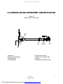
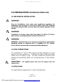
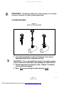
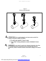
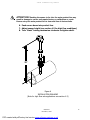
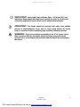
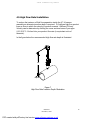
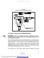
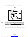
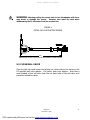
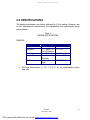
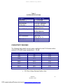
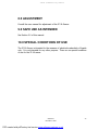
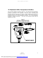
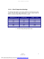
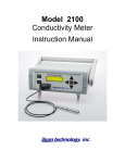
JF-1A CONDUCTIVITY SENSOR
D-2 INCORPORATED
Jet Fuel 1A Conductivity Sensor
Installation & Safe Use Manual
REVISION 3.0
P/N A440-010
This manual covers the installation and use aspects of the D-2 JF-1A Conductivity
Sensor. D-2 continuously strives to meet the full expectations of our customers and we
welcome comments on the structure, content and the ability of this manual to answer
your questions regarding our product. If you have any suggestions or comments please
contact us at [email protected].
A440-010
December, 2005
PDF created with pdfFactory trial version www.software-partners.co.uk
1
JF-1A CONDUCTIVITY SENSOR
Read the instructions in this manual carefully before installing or starting the system.
D-2 Incorporated will accept no liability for damages due to non-observance of this
manual.
If the instructions in the operating manual are not adhered to or are
inadequately adhered to, there shall be no entitlement to services
under the warranty and the CE Declaration of Conformity shall
cease to be valid.
Information in this manual is subject to change without notice and does not represent a
commitment on the part of D-2 Incorporated.
No part of this manual may be reproduced or transmitted in any form or by any means,
electronic or mechanical, without the prior written permission of D-2 Incorporated.
Where manuals are written in several languages, the text it was created in is considered
the original.
D-2 Incorporated
21A Commerce Park Road
Pocasset, MA USA 02559
Phone:
Telefax:
01 508-329-2046
01 508-536-5206
E-Mail:
Internet:
[email protected]
http://www.D-2Inc.com
© Copyright 2005, D-2 Incorporated, Pocasset, MA, USA
A440-010
December, 2005
PDF created with pdfFactory trial version www.software-partners.co.uk
2
JF-1A CONDUCTIVITY SENSOR
Notes for User
WARNING!
There is a danger to life and limb or a risk of serious injury if the notes on
safety are disregarded!
CAUTION!
There is a risk of injury and damage to property if the notes on safety are
disregarded!
ATTENTION!
There is a risk of damage to property if the notes on safety are
disregarded!
IMPORTANT!
Notes on working procedures.
Revision History:
Rev
1
Date
12/19/05
12/23/05
1
2
01/15/06
02/31/06
3
06/15/06
Description
Written
Add Fuel Temperature & Pressure Limits
Add Safety Ground Wire Connections 2-Wire & 4-Wire Diagrams & Descriptions
Editorial Changes
Change use pressure to 16 Bar
Add Ground Wire Lug Use Information (3 Places)
Add RS-232 Maximum Voltages & Currents
Updated System Operating Temperature to 50C
Add Warning on Counter Clockwise Rotation Installation & Removal
A440-010
December, 2005
PDF created with pdfFactory trial version www.software-partners.co.uk
AJF
AJF
AJF
AJF
AJF
3
JF-1A CONDUCTIVITY SENSOR
TABLE OF CONTENTS
OPERATION MANUAL
1.0 GENERAL & LABELING
5
2.0 INSTRUCTION FOR SAFE USE
6
3.0 SENSOR MAJOR COMPONENT IDENTIFICATION
8
4.0 SENSOR INSTALLATION (ASSEMBLING/DISMATLING)
9
5.0 SENSOR REMOVAL
20
6.0 SPECIFICATIONS & MAXIMUM ALLOWABLE VALUES
22
7.0 MAINTENANCE
24
8.0 ADJUSTMENT
25
9.0 DETAILS TO ALLOW SAFE USE AS INTENDED
25
10.0 SPECIAL CONDITIONS OF USE
25
11.0 OPTIONAL 4-20 TEMPERATURE OUTPUT
26
A440-010
December, 2005
PDF created with pdfFactory trial version www.software-partners.co.uk
4
JF-1A CONDUCTIVITY SENSOR
1.0 GENERAL & LABELING
JF-1A Applications
The JF-1A Conductivity Sensor is a 2-Wire 4-20 mA Electrical Conductivity
Measurement Sensor.
Liquid media
The sensor is used for measuring the electrical conductivity of liquid media:
In hazardous locations, Zone I of Explosion Group II C corresponding to EN
guidelines
In hazardous locations Class I, Div. 1, Group B, C and D in accordance with FM
and CSA guidelines
ATTENTION! The sensor is not designed to meter gaseous media or solids.
Manufacturer
Type
D-2 Incorporated
21A Commerce Park Road
Pocasset, MA 02559, USA
II 2G
Code
EEx d [ia] IIC T4
Testing Station
KEMA QUALITY, B.V., Utrechtseweg 310, 6812 AR Arnhem
Certificate #
KEMA05ATEX1252
Ambient Temp Range
-20 to 50 Celcius
Process Max Temperature
40 Celcius
Ambient Max Pressure
16 Bar (235 PSIG)
Maximum Voltage (Loop)
Maximum Current (Loop)
38 VDC
22 mA
Maximum (RS-232 Output)
(RXD) Maximum +/- 25 VDC +/- 5 mA
(TXD) Maximum +/- 5VDC +/- 30 mA (Short Circuited)
Test Voltage
Um = 250 VAC
Maximum (RS-232 Input)
A440-010
December, 2005
PDF created with pdfFactory trial version www.software-partners.co.uk
5
JF-1A CONDUCTIVITY SENSOR
2.0 INSTRUCTION FOR SAFE USE
The D-2 JF-1A Conductivity Meter reads conductivity in picosiemens/meter, fuel
temperature in ITS-90 degrees C, and fully compensated Conductivity in picosiemens/
meter per ASTM D 2624, Appendix X2 in liquid fuels and solvents. The sensor can be
used in a 2 wire 4-20 mA industrial control loop or in conjunction with a serial input
device using RS-232 IEEE Standard ASCII Serial Input Data. Optionally a 2 wire (4-20
mA) temperature interface can be added to allow remote monitoring of fuel
temperature.
WARNING:
Immediately switch off the sensor in the case of emergency!
Until the sensor is fully installed in a filled product line do
not energize sensor.
When using the sensor to measure combustible media,
observe the regulations concerning transport and storage
of combustible liquids.
Observe applicable national regulations for installation abroad.
Only Ex d approved cable entry devices (e.g. cable gland) shall
be used, with the apparatus.
Sensor is intended for use in product lines where the absolute
maximum physical conditions do not exceed the specifications
listed in Section 6.0.
CAUTION:
Sensors must be accessible at all times to facilitate operation
and maintenance. Do not obstruct or block clear access.
Only specially trained and authorized persons are permitted to
maintain and repair JF-1A Sensors and their peripheral
equipment.
Always depressurize the liquid end first before carrying out any
A440-010
December, 2005
PDF created with pdfFactory trial version www.software-partners.co.uk
6
JF-1A CONDUCTIVITY SENSOR
work on the Sensor.
If hazardous or unknown sensor media are used, discharge and
flush the liquid end before carrying out any work on the
sensor.
Observe the safety data sheets of the measured liquids.
Always wear protective clothing (goggles, gloves) when
handling hazardous or unknown liquids! This applies in
particular to working on the liquid end.
Assembly of the JF-1A Sensor with parts not tested and
approved by D-2 Incorporated is prohibited and can result in
damage to persons and property, for which no liability will be
accepted.
Caution: Installation and Removal of the sensor from
pressurized lines care MUST be taken to ensure sensor does not
“fly” back to stop.
Caution: At no time should the main sensor body (electronic
housing) be rotated in a continuous counter clockwise direction
as sensor components may become undone resulting in liquid
(product) ingression into sensor.
A440-010
December, 2005
PDF created with pdfFactory trial version www.software-partners.co.uk
7
JF-1A CONDUCTIVITY SENSOR
3.0 SENSOR MAJOR COMPONENT IDENTIFICATION
Figure 2
Major System Components
7
4
3
2
1
4
6
3
2
1
8
9
1
2
3
4
Ball Valve
Sensor Mount Adaptor
Mounting Nut
Locking Collar
6
7
8
9
Electronics Housing
Electrical Connection Side
Label
Installation Reference Plane
A440-010
December, 2005
PDF created with pdfFactory trial version www.software-partners.co.uk
8
JF-1A Conductivity Sensor
4.0 INSTALLATION ASSEMBLING/DISMATLING
4.1 MECHANICAL INSTALLATION
WARNING!
Prior to Installation, local codes and regulations regarding the
installation and operation of this type of device should be reviewed
and strictly adhered with to ensure safe and reliable operation of the
system.
WARNING!
Installation in Product Lines with Flow Above 1.5 M/sec (5 ft/sec)
must observe recommendations as listed in Section 6.5
WARNING!
WARNING: Local Procedures to reduce the potential for electrostatic
discharge should be observed prior to handling the JF-1 Sensor.
Ensure service personnel have proper grounding equipment.
4.2 PIPE CONNECTIONS
D-2 recommends a 3” long 1” NPT nipple be mounted orthogonal (at a right
angle) to the main product line. If possible the nipple should be mounted
vertical from the section of pipe. The main product line should be hard
mounted and mechanically stable, free of excessive pump or other vibration
sources.
IMPORTANT:
The supplied nipple must meet site piping codes and
requirements.
4.3 PIPE VALVE
The nipple should be supplied with a 1” Open Throat Ball Valve.
A440-010
December, 2005
PDF created with pdfFactory trial version www.software-partners.co.uk
9
JF-1A Conductivity Sensor
IMPORTANT:
The Ball Valve MUST Have a Clear Opening of 1.0” through
its center to allow the D-2 sensor to pass unobstructed.
4.4 INSTALLATION
Figure 4
INSTALLATION DRAWING
1. Turn locking mechanism counter clockwise to loosen sleeve.
Push sleeve down as far as possible on shaft.
IMPORTANT: Prior to nut installation (step 2) onto sensor adaptor
ensure threads are coated with a good quality anti-seize lubricant.
2. Position instrument over fitting on pipe. Tighten 2" mounting
nut onto ball-valve adaptor.
3. Note: Only turn mounting nut with ball valve closed.
A440-010
December, 2005
PDF created with pdfFactory trial version www.software-partners.co.uk
10
JF-1A Conductivity Sensor
Figure 5
INSTALLATION DRAWING
ATTENTION!
Prior to performing the next steps ensure product line
pressure is less than 150 psia (10.0 Bar).
4. Turn ball valve handle 1/4 turn to open.
5. Turn “black” locking mechanism counter-clockwise to loosen
shaft.
WARNING! Do not rotate the main body (electronics housing) other than
in a clockwise direction to assist the sensor in sliding it down into the
product line, counter clockwise rotation could result in damage to the sensor
tip.
A440-010
December, 2005
PDF created with pdfFactory trial version www.software-partners.co.uk
11
JF-1A Conductivity Sensor
ATTENTION!
Pushing the sensor to far into the main product line may
result in damage to sensor and require factory re-calibration or repair.
Ensure entry into main product line is clear and free of obstructions.
6. Push sensor down into product line.
7. Adjust sensor height (see section 4.5 for high flow conditions)
8. Turn “black” locking mechanism clockwise to tighten shaft.
28"
E
PIP L
/
C
Figure 6
INSTALLATION DRAWING
(Note for high flow rate applications see section 4.5)
A440-010
December, 2005
PDF created with pdfFactory trial version www.software-partners.co.uk
12
JF-1A Conductivity Sensor
IMPORTANT!
Under high flow conditions, flow > 1.5 M/sec (5 ft/sec)
installation depth should be modified as outlined in section 6.5 to prevent
vortex flow separation inside critical sensor measurement volumes.
IMPORTANT:
The Sensor should be mounted well away from possible
sources of electromagnetic noise, such as large pump motors, AC power
Lines, or electrical circuits containing large transient switching currents.
WARNING:
Prior to arc welding in proximity to the JF-1A sensor (closer
than 10 meters (30 feet) the sensor should be either removed from the
product line or at a minimum disconnected from all electrical connections to
the sensor.
A440-010
December, 2005
PDF created with pdfFactory trial version www.software-partners.co.uk
13
JF-1A Conductivity Sensor
4.5 High Flow Rate Installation
To reduce the instance of fluid flow separation inside the JF-1A sensor
assembly an alternate insertion depth is required. D-2 defines high flow product
lines as lines in which the velocity of product exceeds 1.5M/sec (5 ft/sec).
Velocity can be determine by dividing the cross sectional area of your pipe
((I.D./2)^2* 3.14 dived into your product flow rate (in equivalent units of
measure).
In the figure below the recommended high flow rate depth is illustrated.
28"
Pipe ID
Figure 7
High Flow Rate Insertion Depth Illustration
A440-010
December, 2005
PDF created with pdfFactory trial version www.software-partners.co.uk
14
JF-1A Conductivity Sensor
4.6 ELECTRICAL INSTALLATION
WARNING:
Only Ex d approved cable entry devices (e.g. cable gland)
shall be used, with the apparatus.
WARNING: All unused ¾” NPT housing openings must be closed using
EN50018 approved plugs.
WARNING:
For the purpose of intrinsic safety the housing must be tied to
earth. Safety Ground wire must be installed under housing ground screw in
user wiring compartment. A cable lug shall be used and the conductor shall
be mounted so that it is secured against loosening and twisting and that the
contact pressure is permanently maintained. Note: the connections to earth
located on the terminal blocks can not be used for this earth connection.
Electrical connection details are shown in figure A. There are 2 screw terminal
blocks, the terminal block with 4 positions has the 4-wire interface, the terminal
block with 3 positions services the 2-Wire Interface. These are “snap” out
Molex screw terminals which can be removed to assist in wiring. Cabling used
should be in compliance with the JF-1A ATEX examination certificate. The 4Wire defined as Power Ground RS-232C Transmit and Receive Data, the 2-Wire
interface defined as 4-20 mA current loop and earth safety ground connections.
Note the 4-Wire input power is polarity protected while the 2-Wire Input Power
input is polarity insensitive; either terminal can be connected to the positive
output of the power source.
A440-010
December, 2005
PDF created with pdfFactory trial version www.software-partners.co.uk
15
JF-1A Conductivity Sensor
Figure 8
2-WIRE ELECTRICAL CONNECTION DETAIL
1 2 3 4
3
2
1
3
2
1
4.7 2-Wire 4-20mA LOOP CONSIDERATIONS
WARNING:
2-Wire Loop Maximum Resistance including wire can not
exceed 500 ohms, or internal intrinsic over voltage safety devices in the JF1A sensor may be activated.
The 4-20 mA Loop supply open circuit voltage must be consistent with the
“Open Circuit Supply” needs of the JF-1A at both its minimum and maximum
indicating currents. The JF-1A has both input voltage limiting protection and
polarity protection.
These protection devices affect user supply voltage
requirements. If proper loop supply voltage is not maintained, errors in
indicated conductivity current may occur. The 4-20 mA loop supply voltage
should comply with specifications section of the manual.
The maximum loop power supply voltage, under all conditions, must also
A440-010
December, 2005
PDF created with pdfFactory trial version www.software-partners.co.uk
16
JF-1A Conductivity Sensor
prevent the voltage across the sensor loop terminals from exceeding the
maximum voltage listed in the specifications section of the manual. If this
condition is not maintained, errors in the current output may occur.
D-2 recommends that a 24 VDC isolated supply be used to power the
instrumentation loop. The supply should have high isolation (>500 Mohm).
The current loop should be wired using shielded twisted pair wire. The shield
should be single point grounded to a solid earth/safety ground.
ATTENTION:
Sensor wiring should be performed as required by local
codes as they apply.
A440-010
December, 2005
PDF created with pdfFactory trial version www.software-partners.co.uk
17
JF-1A Conductivity Sensor
4.8 RS-232 CONNECTIONS Considerations (4-Wire)
Figure 8A
4-WIRE ELECTRICAL CONNECTION DETAIL
1 2 3 4
3
2
1
3
2
1
WARNING: For the purpose of intrinsic safety the housing must be tied to
earth. Safety Ground wire must be installed under housing ground screw in
user wiring compartment. A cable lug shall be used and the conductor shall
be mounted so that it is secured against loosening and twisting and that the
contact pressure is permanently maintained. Note: the connections to earth
located on the terminal blocks can not be used for this earth connection.
The 4 Terminal Screw Connector has both Power Input and RS-232/RS-485
Connections as listed in Table 1 below:
TABLE 1
SCREW TERMINAL CONNECTION PIN DETAIL
A440-010
December, 2005
PDF created with pdfFactory trial version www.software-partners.co.uk
18
JF-1A Conductivity Sensor
TERMINAL
1
2
3
4
Function
Data/Power Ground
RS-232 Data In (RXD)
Power Input +
RS-232 Data Out (TXD)
The RS-232 Interface is fully isolated from the sensor electronics through the
use of optical isolators located in the JF-1A/ATEX sensor.
Data cable for the RS-232 should be low capacitance data cable. Lengths in
excess of 20 meters may result data degradation of the RS-232 signals.
4.9 Power Input (4-Wire)
WARNING: Power supply must be fully isolated and meet all local and site
codes for its use.
Power input to the 4-Wire power connections should be clean filtered DC
voltage in the range of 7 – 35 VDC. Current consumption is approximately 10
mA.
A440-010
December, 2005
PDF created with pdfFactory trial version www.software-partners.co.uk
19
JF-1A Conductivity Sensor
5.0 SENSOR REMOVAL
WARNING: Power must be disconnected before sensor removal.
5.1 DISCONNECT POWER
Turn off system power to the unit and disconnect electrical connections from
the user interface. Remove any conduit connections from the JF-1A Sensor.
Ground the sensor to the main line prior to removal from the line.
5.2 PULL SENSOR BACK
WARNING: Prior to handling sensor ensure operator is properly grounded
to prevent possible electrostatic discharge.
WARNING:
Ensure product line pressure is below 150 psia (10 Bar) prior
to loosening black locking collar. DO NOT HAVE OPERATOR LOCATED IN
FRONT OF THE SENSOR IN THE EVENT THE SENOR “KICKS” OUT DUE TO
HIGH PRODUCT LINE PRESSURE. The operator should maintain a slight
pressure towards the product line at all time that the “locking collar” is been
loose to prevent “blow back”.
WARNING: At no time during removal of the sensor should the main body
(electronics housing) of the sensor be rotated in a continuous counter
clockwise direction. Any such rotation may result in the loosening of the
sensor components and possible liquid (product) ingression into the JF-1A
Sensor. Small rotations or rotations in a clockwise direction are acceptable
to assist in drawing the sensor back past the valve.
Loosen the black locking collar on the retractable mount. Care should be taken
to prevent the sensor from “blow back,” although the retractable mount has an
anti-slide collar to assist in preventing blow back. The sensor reference plane
will be 28” from the adaptor step (see Figure 8) when the sensor is fully pulled
back in the mount. The valve should operate easily and will not come into
contact with sensor when it is fully withdrawn. Product will reduce the
lubrication of the sensor shaft which may increase the friction that is required to
withdraw the sensor.
A440-010
December, 2005
PDF created with pdfFactory trial version www.software-partners.co.uk
20
JF-1A Conductivity Sensor
WARNING: Warning pulling the sensor back to into the adaptor with force
may break or damage the sensor. Extreme care must be used when
withdrawing the JF-1A sensor from the product line.
1
2
3
4
FIGURE 9
DETAIL FULLY RETRACTED SENSOR
28"
minimum length necessary to ensure probe has been withdrawn completely from valve
5.3 CLOSE BALL VALVE
Close the ball valve and loosen the locking nut, which secures the sensor to the
D-2-supplied ball valve adaptor. Pull sensor back from adaptor. Note that a
small residual of fuel will drain from the out board side of the ball valve, and
precaution should be taken.
A440-010
December, 2005
PDF created with pdfFactory trial version www.software-partners.co.uk
21
JF-1A Conductivity Sensor
6.0 SPECIFICATIONS
The electrical parameters are factory calibrated to 1% of reading. However, due
to fuel measurement characteristics, the repeatability and reproducibility limits
are as follows:
Table 2
SENSOR SPECIFICATIONS
SENSORS:
Parameter
Range
Accuracy *
Resolution
Sensor Type
Calibration
•
Conductivity
0 – 500 pS/M
+/- 2 pS/M (+/2%) of Reading
0.1 pS/M
Coaxial
Electrode
Internal Zero &
Scale
Temperature
-5 – 50 C
+/- 0.5 C
0.1 C
Platinum RTD
NIST ITS-90
This is at temperatures +/- 10° C of 20° C for the compensated output
data only.
A440-010
December, 2005
PDF created with pdfFactory trial version www.software-partners.co.uk
22
JF-1A Conductivity Sensor
Table 3
SYSTEM SPECIFICATIONS
ELEMENT
Flow Range
Fuel Process Temperature
Environmental
Temperature
Power 2-Wire Input
Power 4-Wire Input
Pressure
Usage
ATEX Certification
FM Certification
UL Certification
SPECIFICATION
0 – 7.0 M/s Max
-20 – 40 C (T4)
-20 to 60 C Operation
-40 to 80 C Storage
24 VDC Minimum
38 VDC Maximum
7 VDC Minimum
38 VDC Maximum
150 PSIA Maximum
Class 1, Division 2
Type II 2G
EExd [ia] IIC T4
Pending
Pending
CONDUCTIVITY READINGS
The following table details current output readings for the JF-1A sensor with a
nominal 0-500 pS/M range representing 4 – 20 mA.
CONDUCTIVITY (Ps/M)
0.0
62.5
125.0
187.5
250.0
312.5
375.0
437.5
500.0
•
Current (mA)
4.0
6.0
8.0
10.0
12.0
14.0
16.0
18.0
20.0
Voltage * (Volts)
1.00
1.50
2.00
2.50
3.00
3.50
4.00
4.50
5.00
250 Ohm Voltage Sensing Resistor Used
A440-010
December, 2005
PDF created with pdfFactory trial version www.software-partners.co.uk
23
JF-1A Conductivity Sensor
7.0 MAINTENANCE
NOTE: There are no user-serviceable components inside the D-2 JF-1A
Conductivity Sensor. There are NO Electronic adjustments inside the
sensor.
7.1 Calibration Interval
The D-2 JF-1A Conductivity sensor should be calibrated annually. The sensor
can be returned to the factory or the procedures found in the calibration section
of the user manual performed. The instrument has no internal electrical
adjustments that need to be maintained.
7.2 Cleaning
The JF-1A Conductivity Sensor should be cleaned every 6 months of use. Fuel
additives or particulate may build up on the sensor, degrading its performance.
7.3 Sensor
The main electronics housing is sealed to the environment. The housing is
purged prior to sealing with dry nitrogen after drying. If the housing is opened
the unit must be returned to the factory for re-calibration.
7.4 ZERO TESTS
The best indicator of static operation of the sensor is the reading of the sensor
(after appropriate cleaning) in dry air (note excessively humid air may result in
higher zero readings). With the sensor cleaned and dry, zero readings should
be stable and less than 5 pS/M when read from the serial data port. If the
current loop is being monitored zero current should read less than 4.25 mA. If
readings are in excess of these values or unstable readings occur, the unit
should be returned to the factory for servicing and possible re-calibration.
A440-010
December, 2005
PDF created with pdfFactory trial version www.software-partners.co.uk
24
JF-1A Conductivity Sensor
8.0 ADJUSTMENT
Consult the user manual for adjustment of the JF-1A Sensor.
9.0 SAFE USE AS INTENDED
See Section 2.0 of this manual.
10.0 SPECIAL CONDITIONS OF USE
The JF-1A Sensor is intended for the measure of electrical conductivity of liquids
only. It is not intended for any other purpose. There are no special conditions
of use for the JF-1A sensor
A440-010
December, 2005
PDF created with pdfFactory trial version www.software-partners.co.uk
25
JF-1A Conductivity Sensor
11.0 Optional 2 Wire Temperature Interface
The connection details are shown in figure 8. The optional 2-wire temperature
interface is connected to JP2 Terminals. These are “snap” out Molex screw
terminals which can be removed to assist in wiring. Cabling used should be in
compliance with the JF-1A Ex examination certificate. The 2 wire temperature
interface is “polarity insensitive”. The loop is not powered; power must be
supplied by the user.
Figure 8
OPTIONAL TEMPERATURE LOOP
ELECTRICAL CONNECTION DETAIL
1 2 3 4
3
2
1
3
2
1
A440-010
December, 2005
PDF created with pdfFactory trial version www.software-partners.co.uk
26
JF-1A Conductivity Sensor
11.1 2-Wire 4-20mA LOOP CONSIDERATIONS
WARNING:
2-Wire Loop Maximum Resistance including wire can not
exceed 500 ohms, or internal intrinsic over voltage safety devices in the JF1A sensor may be activated.
WARNING: For the purpose of intrinsic safety the housing must be tied to
earth. Safety Ground wire must be installed under housing ground screw in
user wiring compartment. A cable lug shall be used and the conductor shall
be mounted so that it is secured against loosening and twisting and that the
contact pressure is permanently maintained. Note: the connections to earth
located on the terminal blocks can not be used for this earth connection.
The maximum loop power supply voltage, under all conditions, must also
prevent the voltage across the sensor loop terminals from exceeding the
maximum voltage listed in the specifications section of the manual.
D-2 recommends that a 24 VDC isolated supply be used to power the
instrumentation loop. The supply should have high isolation (>500 Mohm), and
be single point grounded. The current loop should be wired using shielded
twisted pair wire. The shield should also be single point grounded to a solid
earth ground.
A440-010
December, 2005
PDF created with pdfFactory trial version www.software-partners.co.uk
27
JF-1A Conductivity Sensor
11.2 4 – 20 mA Temperature Readings
The following table details current output readings for the JF-1A sensor with a
nominal -10 to 60 Celsius range representing 4 – 20 mA. (Please consult the
factory for alternate range settings of the current output):
Temperature (C)
-10.0
0.0
10.0
20.0
30.0
40.0
50.0
60.0
•
Current (mA)
4.0
6.3
8.6
10.8
13.1
15.4
17.7
20.0
Voltage * (Volts)
1.00
1.57
2.14
2.71
3.28
3.85
4.42
5.00
250 Ohm Voltage Sensing Resistor Used
A440-010
December, 2005
PDF created with pdfFactory trial version www.software-partners.co.uk
28