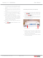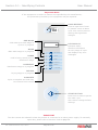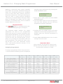
1
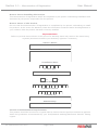
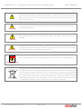
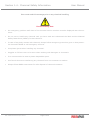
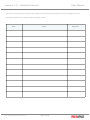
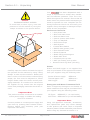
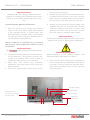
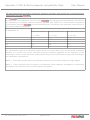
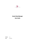
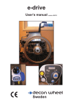
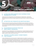
User Manual
®
User Manual
Rev.C
Medisafe International, Twyford Road, Bishop’s Stortford, Hertfordshire CM23 3LJ, U.K.
T: +44 (0)1279 461641 F: +44 (0)1279 461643 www.medisafeinternational.com E:[email protected]
Ref: PICO-EVO UM 1 09/11 Rev.C
Page 1 of 46
Table of Contents
User Manual
Section
1
Title
Page
Introduction
4
1-1
Memorandum of Registration
5
1-2
Important Safety Symbols and Explanation
6
1-3
Important Safety Information
7
1-4
Chemical Safety Information
8
1-5
Trained Personnel
9
1-6
Introduction
10
2
Installation
12
2-1
Unpacking
13
2-2
Installation Requirements
14
2-3
Installation
16
2-4
Connecting to a Data Logging System
18
Operation
19
3-1
Identify Controls
20
3-2
Changing Language
21
3-3
Changing Time & Date
22
3-4
Changing Wash Programmes
23
3-5
Important Information on Loading
24
3-6
Operating Instructions
25
3-7
Routine Checks
27
3-8
Purging AWT After Replacement
29
3
Ref: PICO-EVO UM 2 09/11 Rev.C
Page 2 of 46
Table of Contents
User Manual
Section
3-9
Title
Page
Purging Chemical After Replacement
30
Manual Door Release
31
Technical
32
4-1
Operating Process
33
4-2
Fault Finding Guide
34
4-3
Technical Specification
35
4-4
Warranty
37
4-5
Service Record
39
4-6
Decontamination Guide
40
4-7
Decontamination Certificate
41
3-10
4
Appendix I
Ref: PICO-EVO UM 3 09/11 Rev.C
EMC & Electromagnetic compatibility Data
Page 3 of 46
42
User Manual
®
Section 1: Introduction
Rev.C
Medisafe International, Twyford Road, Bishop’s Stortford, Hertfordshire CM23 3LJ, U.K.
T: +44 (0)1279 461641 F: +44 (0)1279 461643 www.medisafeinternational.com E:[email protected]
Ref: PICO-EVO UM 4 09/11 Rev.C
Page 4 of 46
Section 1-1 - Memorandum of Registration
User Manual
Note to Person Installing this Product
This Memorandum of Registration MUST be completed by the person undertaking installation and
witnessed by the person responsible for this product.
Note to Owner of this Product
Be sure that this Memorandum of Registration is completed by the person undertaking to install
the product. In the event of a Warranty Claim the information contained within this Registration is
your evidence that the product has been correctly installed.
Important Note:
Failure to provide this evidence in the event of a warranty claim may result in the claim being
rejected (this does not affect your statutory rights as a customer).
Owner’s Name:
Installation Address:
Installation Date:
Product type
Auto Dosing Facility:
Yes
No
Serial Number:
Software Version:
Installed by:
Witnessed by:
Service and Maintenance Requirements:
This product should be serviced on a regular basis to ensure that the product continues to perform
within the guidelines recommended by your local/national washing/disinfection Periodic Testing
regime.
Ref: PICO-EVO UM 5 09/11 Rev.C
Page 5 of 46
Section 1-2 - Important Safety Symbols and Explanation
User Manual
If this symbol appears on equipment then the documentation must be consulted in all cases where symbol 14 of table 1 (caution) is marked, in order to
find out the nature of the potential hazard and any actions which have to be
taken to avoid them.
Warning
Caution
Warning
This symbol alertes you to situations that may cause serious body harm, death
or property damage.
This symbol alerts you to situation that may cause body injury or property
damage.
This symbol indicates the presence of electric shock hazards. Dangerously high
voltages are present inside the product. Do not remove the outer casing. Refer
servicing and repair to qualified personnel only.
important
This symbol indicates that “Important Note(s)” are manufacturer recomendation.
Important Note
This marking indicates that this product should not be disposed with Municipal wastes
throughout the EU. To prevent possible harm to the environment or human health
from uncontrolled waste disposal, recycle it responsibly to promote the sustainable
reuse of material resources. In accordance with European Directive WEEE 2002/96/
EC, please contat your local recycling authorities for collection centers to deliver
waste electrical and electronic equipment or the equipment can also be handed over
to a Medisafe distributor when purchasing a new washer disinfector.
Ref: PICO-EVO UM 6 09/11 Rev.C
Page 6 of 46
Section 1-3 - Important Safety Information
User Manual
Electrical
Decontamination
This product operates from mains electricity
and is supplied with the correct connector for
the market into which it is sold. If the supplied
connector is removed during installation, be
sure to observe the correct colour code when
reconnecting to an appropriate plug or fused
spur.
This product MUST be decontaminated in
accordance with local regulations before transportation. In the event that the product must
be returned to the supplier, it is vital that the
Decontamination Certificate on page 40 of this
manual is completed and returned with the
product.
Chemicals
Warning
Dangerously high voltages are present
inside the product. Do not remove the outer
casing. Refer servicing and repair to qualified
personnel only.
Only Medisafe detergents and additives are
approved and recommended for use in this
product. Using non-approved chemicals may
cause damage to the product and could void
both your warranty and your guarantee of
performance.
Door Release
Warning
To prevent fire or shock hazard, do not expose this product to rain or moisture.
Heat
The effective operation of this product relies on
water being heated to elevated temperatures
which may cause scalding if care is not taken
during operation. Although the automatic door
locking system will assist in preventing such
injuries, care must be taken when loading and
unloading instruments after a cycle has been
completed.
For your protection, the loading door is fitted
with an electric safety locking system and can
not be operated unless the product is connected
to a mains power supply. An override facility
exists which allows the door to be opened
manually in an emergency or if power to the
product becomes interrupted. A special key is
provided for this purpose.
Installation and Maintenance
This product has been factory tested to
ensure that it performs according to its design
parameters. It is essential that the correct
installation procedure is adhered to and that
the recommended regular maintenance checks
are performed to ensure that it continues to
operate within design parameters.
Warning
Water temperature within the wash chamber
may exceed 85OC during and after operation.
Take care when removing items on completion
of a cycle and allow good time for the items to
cool to a safe temperature before handling.
Ref: PICO-EVO UM 7 09/11 Rev.C
Page 7 of 46
Section 1-4 - Chemical Safety Information
User Manual
User must read this message prior to any chemical handling
Chemical Safety Note
• An emergency guideline wall chart of the chemical used in machine must be displayed near the machine.
• Do not use or handle any chemical until you have read and understood the label and the Material
Safety Data Sheet (MSDS) for that chemical.
• In case of any body contact with chemical, always follow emergency procedure given in that particular chemical’s MSDS or call emergency services.
• Use plastic gloves when handling any chemical.
• Goggles or full face visor to be worn when working with detergent or chemicals.
• It is recommended to wear a plastic disposable apron.
• Use funnel whenever transferring any chemical from one container to another.
• Always follow MSDS instructions for safe disposal of chemical container.
Ref: PICO-EVO UM 8 09/11 Rev.C
Page 8 of 46
Section 1-5 - Trained Personnel
User Manual
The owner of this equipment has the responsibility for giving training and keeping records of training to the user.
The following table can be used for keeping training records
Date
Ref: PICO-EVO UM 9 09/11 Rev.C
Name
Page 9 of 46
Signature
Section 1-6 - Introduction
The
User Manual
Washer Disinfector
The
range of washer disinfectors
have been designed to clean various surgical instruments, implements, and associated
products used within a medical environment.
This objective is achieved through separate
wash and disinfection stages of an automatic
cycle. Optimum decontamination is ensured
though the use of sophisticated electronics
which control and monitor the entire cycle
without any need for user input.
If a wash/disinfect cycle fails to achieve any
one of the predetermined parameters then the
system reports a failed cycle. The unit registers
such a failure and brings it to the attention of
the operator, who is then unable to remove the
load without being aware that the cycle has
been aborted.
General Wash
The
is primarily intended to wash
and disinfect general medical instruments
which are placed within a range of removable
baskets. A rotating spray arm distributes fluid
evenly over the load.
Lumen Wash
As well as a rotating spray arm, the
adds the facility to wash and disinfect the inside of lumen devices such as dental hanpieces
which are connected on high pressure handpiece manifold.
just before the wash cycle by automatic measured dispensing system into the chamber from
an external container.
Important Note:
It is vital that the correct programme is chosen
according to the detergent being used. Details
can be found in Section 3-4.
Disinfecting
Effective thermal disinfection is achieved by
raising the temperature of the final rinse water
within the wash chamber to a predetermined
level, and then maintaining this temperature for
a period of time specifically identified as being
acceptable by international decontamination
standards.
Drying
Drying is achieved by forced hot air circulation within the chamber to remove residual
moisture from the instruments and hand piece
channels leaving the instrument load dry and
ready for the sterilisation process.
Scale Inhibitor
To improve cleaning performance, and to help
reduce scaling during thermal disinfection, a
de-scaling additive (AWT Fluid) is automatically
introduced into the cycle. This helps to ensure
that the unit maintains optimum performance
throughout its operational life.
Auto Dosing
All
models are supported by Automatic Dosing System, which introduces a controlled amount of detergent from an external
container during the appropriate stage(s) of a
wash cycle.
Washing
Washing is achieved using unique, specially
formulated and clinically validated detergents
which are introduced into the cycle during the
operating cycle to clean away fat, protein,
starch, body fluid residue, etc. The detergent
(3EZyme or Medisafe PH safe) is dispensed
Ref: PICO-EVO UM 10 09/11 Rev.C
Page 10 of 46
Section 1-6 - Introduction
User Manual
Compliance
Environmental Policy
All variants in the
range have
been designed to perform within the
guidelines recommended by international
decontamination Standards. A stringent quality
control programme ensures that every unit
is manufactured and tested under controlled
conditions to ensure that all products perform
identically.
Waste electrical and electronic products must
not be disposed of with household waste.
Please recycle where facilities exist. Check
with your Local Authority or Distributor for
recycling advice.
Declaration of CE Conformity
The
range is designed and
manufactured in the UK by Medisafe UK Ltd.
and complies with the essential requirements
of the Medical Devices Directive 93/42/
EEC (where appropriate). All products are
CE compliant and are registered as Class
IIa devices through the application of all 18
rules within Annex IX of the Medical Devices
Directive 93/42/EEC.
Ref: PICO-EVO UM 11 09/11 Rev.C
Manufacturer Information:
Medisafe UK Ltd
The Snap Factory
Twyford Road
Bishop’s Stortford
Hertfordshire
CM23 3LJ
UK
Telephone: +44 (0) 1279 461641
Fax:
+44 (0) 1279 461643
E-mail:
[email protected]
Web:
www.medisafeinternational.com
Page 11 of 46
User Manual
®
Section 2: Installation
Rev.C
Medisafe International, Twyford Road, Bishop’s Stortford, Hertfordshire CM23 3LJ, U.K.
T: +44 (0)1279 461641 F: +44 (0)1279 461643 www.medisafeinternational.com E:[email protected]
Ref: PICO-EVO UM 12 09/11 Rev.C
Page 12 of 46
Section 2-1 - Unpacking
User Manual
Caution:
EXCESSIVE WEIGHT HAZARD
To avoid back or other injury, have two
persons to lift the washer by using the
straps as shown in the picture below.
Lifting Straps
Carefully open the carton and with the help of
two persons lift the machine by using “lifting
Straps” to take out the machine. Please note
that in order to lift the machine without lifting
straps, the feet must be adjusted to 25mm
height. Please retain the carton and all packaging materials. If it needs to be returned to
the supplier for any reason then the original
carton and packaging materials should be reused.
Important Note
This product must be connected to a suitable
mains power supply to enable the loading
door to be released.
Connect product to a mains power supply and
open door by pressing Door Release button.
Remove basket and accessory pack (see
important note above).
Ref: PICO-EVO UM 13 09/11 Rev.C
Your
has been despatched with a
range of accessories to enable easy installation and efficient operation. Their use is detailed throughout this manual. Ensure that all
these items are present before attempting to
install or operate the unit. Complete the following Enclosures Check List and notify your
supplier of any shortages or damaged components as soon as possible.
Enclosures Check List
• 1 Gray drain hose
• 1 Blue cold water hose
• 1 Red Hot Water hose
• 1 Carrier system with divider
• 1 Tray c/w Manifold
• 1 Instrument Trays
• 1 Rack System
• 1 Dental Burr Basket
• 1 RS232 data (printer) lead
• 1 Door Release Probe
• 1 Owner’s Manual
• 1 Bottle 3E-Zyme detergent
• 1 Bottle AWT Fluid
• 1 Chemical-pick-up tube
• 1 AWT (de-scaler) pick-up tube
• Routine Check Log Book (UK Only)
Printer
Printer and Medi-Logger is not supplied but
may be purchased as an approved accessory
from your supplier using the following code:
Printer & Power supply:
Thermal paper rolls:
Medi-logger: MED1014
MED1014.1
M20070G
Detergents and Water Treatment Fluid
Packs of approved detergent and bottles of
water treatment fluid may be purchased from
your supplier using the following codes.
3E-Zyme: MED8035 (1 x 4 Litre bottle)
AWT Fluid: MED1000.09 (4 x 0.5 Litre bottles)
Important Note:
Using non-approved chemicals, accessories,
and replacement parts may cause damage
to this product and could result in disputed
warranty claims. Please read safety instructions
before using any chemical on section 1-4.
Page 13 of 46
Section 2-2 - Installation Requirements
User Manual
Installation
■■ The product must be unpacked and sited on a stable and level work top capable of supporting a maximum weight
of 55kgs and should be installed 50mm away from side walls and 75mm from back wall for ventilation purposes.
■■ There should be enough free space provided near the machine for safe and efficient maintenance in future.
Water Supply
3
1
Hardness (CaCO ):
< 55ppm as per HTM0105, refer page 65 clause 17.10
Pressure:
1 - 3 Bar 2
Temperature:
15 – 25OC (Cold), 50 – 60OC (Hot)
1 x shut off valve with ¾” BSP male thread (Cold)
Connections:
1 x shut off valve with ¾” BSP male thread (Hot)
Position of connections: Within 1 meter of proposed installation
Electrical Supply
Voltage & Frequency:
230 Vac nominal (+/- 5%) @ 50Hz
Outlets:
2 x 13A, 3 pin outlets with total capacity of 13A
Position of outlets:
Within 1 meter of proposed installation
Method of disconnect:
Remove mains plugs
Note: In case of washing glass products, i.e.: Mirrors, RO water supply(<20 μS) is recommended
Drainage System
Type:
2 x 1½” dia. drains fitted with suitable traps
Position:
Below the drain outlet of the machine
Capacity:
>20 l/minute
Printer shelf
Dimensions
Suitable provision (230mm wide x 280mm deep) should be made for locating the Thermal
Printer. Power supply connection for printer should be situated near the printer shelf.
Position:
Above or to right of the machine and within 1 meter from the machine
Chemical Shelf
Dimensions
Suitable provision for detergent & AWT (270mm wide x 230mm deep) should be made.
Position:
Detergent & AWT must be kept at machine level
1.
If mains water pressure is lower than 1bar, a pressure booster pump must be installed and if water pressure is higher than 3bar than a
pressure reducing valve must be installed. Please see part numbers and prices below
2.
Part Number
Description
Price excluding VAT
MED8931
Pressure booster pump Assembly
£290.00
VALVE025
Pressure reducing Valve
£150.00
Above this value AWT must be used during the cycle. The amount of AWT depends on the hardness of the water, please contact Medisafe UK
Ltd service department (Tel: 01279858400).
3.
In case Printer and Medi-Loggers are connected to same machine, an extra 13A mains power outlet must be installed
4.
There are two drain hose connected to the machine for overflow and machine’s drain.
Note: Failure to install your
Ref: PICO-EVO UM 14 09/11 Rev.C
following the above guidelines could invalidate your warranty.
Page 14 of 46
A
B
C
D
E
F
G
H
A
1
1
ECN
477.80
468.42
550.1
REVISION
2
2
637.50
DESCRIPTION
3
3
DATE
4
4
5
5
557
6
856.5
6
7
7
8
138.10
8
Mains
Cord
FINISH:
9
Detergent Input
AWT Input
Pressure Port
10
RO Water
Inlet
Hot Water
Inlet
11
Cold Water
Inlet
Machine
Drain
D15040
12
Overflow
Drain
New Pico Assembly
-0,3
-0,2
A2
A
B
C
D
E
F
G
SHEET 1 of 1
+0,2
Scale 1:5
All measurements in mm
Requires a clearance of 20mm all round and 50mm on the rear
Tolerances unless otherwise specified
Ensure good clean
finish, remove all burrs,
sharp edges and
production marks.
SCALE: 1:5
Title:
Revision: A
State: BEING_MODIFIED
Dimensions over 250 up to 400 0.5
Dimensinos over 400 up to 1500 0.8
Dimensions over 1500 up to 3000 1.2
Date: 01-02-2011
Name: ajedynak
MATERIAL:
Dimension up to 50 0.1
Dimensions over 50 up to 120 0.2
Dimensions over 120 up to 250 0.3
Clean and Burrfree
PROPRIETARY AND CONFIDENTIAL
THE INFORMATION CONTAINED IN THIS
DRAWING IS THE SOLE PROPERTY OF
MEDISAFE UK Ltd. ANY REPRODUCTION
IN PART OR AS A WHOLE WITHOUT THE
WRITTEN PERMISSION OF
MEDISAFE UK Ltd IS PROHIBITED.
DWG NO.
Medisafe UK Limited Unless otherwise specified:
Twyford Road
All dimensions in millimeters
Bishop's Stortford
CM23 3LJ
13/01/09
z:\cad database\MED - MET - FAB\Development\
Page 15 of 46
Ref: PICO-EVO UM 15 09/11 Rev.C
User Manual
Section 2-2 - Installation Requirements
Section 2-3 - Installation
User Manual
Important Note:
Medisafe (UK) Ltd. strongly advise that this
product be installed and commissioned by Medisafe or by a suitably qualified person before
use.
and remove mains plug.
5. Identify two grey plastic convoluted drain hoses attached at the back of the unit. Connect
these hoses to suitable mains drain sited below the level of the drain outlet on the unit.
Connecting the Washer Disinfector
1. Place the product on a sturdy, level surface
within 1 meter of a mains supply (two supplies
if the optional printer or Medi-Logger has
been specified), suitable drain, and suitable
hot and cold water supply as detailed with in
the Installation Requirements.
6. Identify the blue and Red water supply hose
supplied with the unit. Connect both of them
with the respective cold and hot water inlet
given at the lower rear of the unit. Connect
the other end to a suitable water supply.
Important Note:
Ensure that the black plastic washer fitted to the
supply hose end is in place before tightening.
Mains isolation is achieved by removing
the plug so ensure that the outlet is easily
accessible.
Important Note:
The
washer disinfector must earthed.
2. Connect the mains plug into the switched outlet and switch on. This product must be connected to a suitable mains power supply to
enable the loading door to be released.
3. Open door and remove any protective
packaging and loose items from inside the
wash chamber.
4. Close door, switch mains off at power outlet,
Chemical Safety Note:
Before handling of any chemical please read
Chemical Safety Information on page 7.
7. There are two quick release ports provided on
rear of chassis and are labelled as “Detergent”
and “AWT”. Remove cap from 3E-Zyme detergent bottle and place filter on end of pick-up
tube into bottle.
RO Water Supply
Hot Water Supply
RS232 Data lead
Cold Water Supply
connection for Printer
& Medi-Logger
Mains Drain
+ Overflow
Detergent
Ref: PICO-EVO UM 16 09/11 Rev.C
AWT
Page 16 of 46
Section 2-3 - Installation
User Manual
8. Fit connector on other end of pick-up tube
to quick release port labelled as “Detergent”.
9. Similarly, remove the cap from AWT bottle and place inlet tube with cap on the
bottle.
10.Fit connector on other end of pick up tube
to quick release port labelled as “AWT”.
11.Plug the mains plug into a suitable
switched outlet and switch on.
12.After installing new detergent & AWT it
is important to purge detergent and AWT
before using the machine. The guidelines
to purge detergent and AWT are given on
page 34 and 35 respectively.
13.Turn ON the water supply and check for
any leaks.
14.Your
Washer Disinfector is now
ready to use.
Connecting the Printer (If supplied)
1. Identify the RS232 Data Lead supplied with
the
. Connect the 3.5mm jack
plug to the data port on the lower rear panel of the
unit.
2. Connect the multi-pin plug on the other end
of the RS232 Data Lead to the connector on
the rear of the printer .
RS232 Data Lead
Power Lead
3. Identify the plug-top power supply packed
with the printer . Connect to socket on rear
of printer and plug into a suitable mains
supply outlet and switch ON.
4. Turn the Printer ON using the switch located
on the left hand side.
Ref: PICO-EVO UM 17 09/11 Rev.C
Page 17 of 46
Section 2-4 - Connecting to a Data Logging PC
User Manual
Connecting to a Data Logging PC.
The
transmits data of a wash cycle from the serial port at a speed 2400 bits
per second (8 data bits, no parity, 1 start bit,
1 stop bit, no handshaking). As an alternative to a printer, this data may be sent to a
logging device or to a computer via the serial port COM1 or COM2 and Microsoft’s Hyper
Terminal programme.
1.Identify the RS232 Data Lead (see image
on left) supplied with the unit. Connect the
3.5mm jack plug to the data port on the
lower rear panel of the unit.
6.The name of the Hyper Terminal bar has
changed to ‘PicoHyper – Hyper Terminal’ and
you now have your own Hyper Terminal.
7.From the File menu, select Properties >>
Settings >> Terminal Keys:
2.Connect the multi-pin plug on the other
end of the RS232 Data Lead to the COM1
or COM2 port on the PC.
3.Locate the Hyper Terminal program in (Programs\Accessories\Communications\HyperTerminal) and click Hyper Terminal.
4.Enter name, e.g. ‘PicoHyper’, and select an
icon from those provided. Click ‘Ok’.
5.By default, COM1 is selected as the
communications port. Click ‘Ok’.
Ctrl+H is selected
Emulation is set to ‘Auto Detect’
Terminal ID is set to ANSI
Buffer is set to 500
Tick ‘append line feeds to receiving ends’
Tick ‘wrap lines that exceed terminal
width’
Click ‘Ok’ to accept port initialization
8.From the Transfer menu, select Capture
Text. The incoming data needs to be stored
in a file so enter the name of a directory
and filename, e.g., ‘C:\PicoHyper\DataLog.
txt’ or browse around and find a suitable
folder before adding the name of the file
you want to save the data in. Click ‘Start’.
9.The PicoHyper Hyper Terminal is now ready
and, if linked to a
, will be receiving data.
10.When the PicoHyper is closed, all received
data will be saved in the DataLog file. Next
time you use the Hyper Terminal, use the
File menu and select Open. When you
choose to open your Hyper Terminal (i.e.,
click ‘PicoHyper’), go to the Capture Text
menu and either enter a new file name for
the data or retain the existing one, in which
case new data will be appended to it. When
you have made your choice, click ‘Start’ to
begin receiving data when the
is
connected.
Washer
ID : 1H15526
Cycle
No: 00083
Cycle start P1
Page 18 of 46
17-08-05
14:06:35
Draining
14:06:43
_
Ref: PICO-EVO UM 18 09/11 Rev.C
14:06:35
Draining
User Manual
®
Section 3: Operation
Rev.C
Medisafe UK Ltd, Twyford Road, Bishop’s Stortford, Hertfordshire CM23 3LJ, U.K.
T: +44 (0)1279 461641 F: +44 (0)1279 461643 www.medisafeinternational.com E:[email protected]
Ref: PICO-EVO UM 19 09/11 Rev.C
Page 19 of 46
Section 3-1 - Identifying Controls
User Manual
Important Note:
If the equipment is used in a manner not specified by the manufacturer,
the protection provided by the equipment may be impaired
DOOR RELEASE
Press to open door. Press
in ‘paused’ mode to abort
cycle. Also used to amend
settings during default
changes.
PRE-WASH
Cold water pre-wash stage of
cycle is in progress
WASH
Main wash stage is in progress
PRE WASH
WASH
RINSE
Load is being rinsed prior to
disinfection stage
LCD DISPLAY
Indicates wash/
disinfect information
at every stage of cycle
and displays any error
messages
RINSE
DISINFECT
DISINFECT
Disinfection stage is in progress
DRYING
COMPLETE
DRYING
Drying stage is in progress
COMPLETE
Cycle is complete and load may
be removed once cooled
START BUTTON
Press once to start or pause
the wash cycle.
Also used to change default
settings.
IMPORTANT
The door cannot be released unless the product is connected to a mains power supply. To manually
open door, please refer to Section 3-10 on page 30.
Ref: PICO-EVO UM 20 09/11 Rev.C
Page 20 of 46
Section 3-2 - Changing Language
User Manual
Changing Language
The LCD display on the front panel of the
product can be programmed to display text in
one of four different languages. Once selected,
a language becomes the default setting until
the procedure is repeated and an alternative
selection is made. The languages are scrolled
in the following order:
1.
2.
3.
4.
5.
French
German
Spanish
English
Japanese
Procedure
Important Note:
The time allowed to make an entry is
relatively short so prompt input is required
once the sequence has been commenced.
1.Disconnect product from mains supply, wait
a few seconds, and then reconnect.
2.Observe the messages shown on the LCD
display whilst following the procedure.
3.Press and hold the START button until
‘select language’ prompt is displayed.
4.Press and hold the START button until
required language is displayed.
5.Press the DOOR RELEASE button once
only.
6.The selected language is now stored.
Important Note:
If product is not fitted with a removable
mains plug then consult a qualified person
before attempting to disconnect power
supply.
Ref: PICO-EVO UM 21 09/11 Rev.C
Page 21 of 46
Section 3-3 - Changing Time & Date
User Manual
Procedure
1.Ensure that the following screen is displayed
before attempting to adjust programme,
date, or time settings.
Load Instruments
Check Detergent
2.Press and hold DOOR RELEASE button for
at least 2 seconds.
The following screen will now be displayed.
Holding the START button will cause the
display to scroll through programmes 1 to
4. (See Changing Programmes in Section
3-4 for details on setting the correct
programme).
Set Clock & Prog
PROG 1
3.After a few seconds the following screen
will be displayed with a prompt flashing
before the HOUR segment of the display.
Press and hold the START button until the
correct HOUR is displayed.
8.Momentarily press START button.
9.The following screen will now be displayed
with a prompt flashing before the DAY
segment of the display. Press and hold
the START button until the correct DAY is
displayed.
Set Clock & Prog
DATE _01:01:00
10.Momentarily press the START button.
11.The following screen will now be displayed
with a prompt flashing between the DAY
and MONTH segments of the display. Press
and hold the START button until the correct
MONTH is displayed.
Set Clock & Prog
DATE 01_08:00
12.Momentarily press the START button.
13.The following screen will now be displayed
with a prompt flashing between the MONTH
and YEAR segments of the display. Press
and hold the START button until the correct
YEAR is displayed.
Set Clock & Prog
TIME _00:00:40
4.Momentarily press the START button.
5.The following screen will now be displayed
with a prompt flashing between the HOUR
and MINUTES segments of the display.
Press and hold the START button until the
correct MINUTES are displayed.
Set Clock & Prog
TIME 14_00:40
Set Clock & Prog
DATE 01:08_00
14.Momentarily press the DOOR RELEASE
button once to save changes and exit
menu or press START to return to step 2
(above).
6.Momentarily press the START button.
7.The following screen will now be displayed
with a prompt flashing after the SECONDS
segments of the display. Press and hold the
START button until the correct SECONDS
are displayed.
Set Clock & Prog
TIME 14:30:40_
Ref: PICO-EVO UM 22 09/11 Rev.C
Page 22 of 46
Section 3-4 - Changing Wash Programmes
Washing is achieved using unique, specially
formulated and clinically validated detergents
which are introduced during the operating
cycle to clean away fats, proteins, starches,
body fluid residues, etc. Two types of detergent
may be used, a liquid enzymic detergent
(3E~Zyme) or a liquid alkaline detergent. Both
types of detergent are drawn into the wash
chamber, via a flexible hose, from a container
located adjacent to the unit.
User Manual
and then open loading door by pressing the
DOOR RELEASE button.
Load Instruments
Press START
2.Once door is open, press and hold DOOR
RELEASE button.
3.Use the START button to scroll through the
time and date settings until the following
programme prompt is displayed.
Important Note:
The
MUST be reprogrammed each
time the detergent type is changed.
The following tables indicate the target
parameters for each of the programmes
which must be met to ensure compliance with
International Standards. The accuracy of these
parameters may be monitored by observing
a print-out from the Thermal Printer (if supplied) or by viewing the Front Panel LCD as a
cycle progresses. This should be done every
day as part of your ACT (Automatic Control
Test) - See Routine Checks in Section 3-7 for
more information.
Changing Programmes
Set Clock & Prog
PROG 1
4.Holding down the START button will cause
display to scroll through programmes 1 to 4.
Release when the required programme is
displayed.
5.Press DOOR RELEASE button once to save
changes and exit menu.
Important Note:
Once selected, a programme becomes the
default until the procedure is repeated and
an alternative selection is made.
To change programmes follow this procedure:
1.Ensure that the following screen is displayed
P1
(Intensive)
P1
(Express)
P2
(Medi-PH-Safe)
P3
P4
(3E~Zyme) (Medi-PH-Safe)
No. of Pre-Wash
002
000
001
001
001
Pre-Wash duration
3 mins
0mins
3 mins
3 mins
3 mins
Main Wash duration
10 mins
5 mins
5 mins
5 mins
5 mins
Main Wash temperature
52°C
42°C
53°C
43-45°C
53°C
No. of Rinses
003
002
002
002
002
Rinse duration
1min
1 mins
1 mins
1mins
1 mins
Disinfection duration
10 mins
1 mins
10 mins
10 mins
10 mins
Disinfection temperature
82°C
90°C
80 - 85°C
80 - 85°C
80 - 85°C
Drying
25 mins
10 mins
20 mins
20 mins
20 mins
Drying temperature
82°C
70 - 82°C
82°C
82°C
82°C
Ref: PICO-EVO UM 23 09/11 Rev.C
Page 23 of 46
Section 3-5 - Important Information on Loading
User Manual
Important Information on Loading Instruments
The capacity of maximum load on
with 6 dental hand pieces.
Benchtop Washer Disinfector is 86 Instruments
When loading instruments be sure to observe the
following precautions:
Do not drop items into the chamber.
Do not Instruments should be load-
ed in such a way so that spray arms
movement is not distracted.
use Dental Handpieces that
are compliant with Washer Disinfector
cleaning and clearly marked with the
following symbol.
Always
Do not over load the basket.
Ref: PICO-EVO UM 24 09/11 Rev.C
Page 24 of 46
Section 3-6 - Operating Instructions
User Manual
Important Note:
If the equipment is used in a manner not specified by the manufacturer,
the protection provided by the equipment may be impaired
Loading the Basket
Fit dental hand piece on the manifold (if available).
Note that whenever dental hand-pieces are
placed into manifold, it is important that any
spare dental hand piece holder on manifold
are blanked off with the caps supplied with the
machine. This will ensure that an effective irrigation flow is achieved through each dental
hand piece device and not by-passed through
the spare Luer connectors.
3.Observe the messages shown on the LCD
display and follow this procedure:
4.If this message is displayed then refer to
“AWT Replenishment”.
Load Descaler
Press START
5.Press START button once.
Place load into large basket and slide into
the wash chamber, ensuring that the basket
locates correctly in docking port in rear of
wash chamber.
Note that water is sprayed up from the bottom
of the chamber so large items, such as trays
and bowls, should NOT be placed flat on the
bottom of the large basket as this will obstruct
the water spray.
Important Note:
Do not overload the large basket so that
water spray is obstructed.
If AWT Fluid has already been added then
continue. If not, then refer to AWT Fluid
Replenishment in Section 3-8.
(The descaler messages will only be shown
at very first power-up or when AWT Fluid is
low.)
IF Descaler IN
Press START
6.Press START button once.
7.When the following message is displayed,
load instruments. Press START button
once.
Load Instruments
press START
Commencing a Cycle
1.Apply power to the product and press the
DOOR RELEASE button to open the door.
9.When the following message is displayed,
ensure that all instruments are correctly
loaded and press START button once.
IF All Loaded
Press START
Warning:
Ensure that the filter on the pick-up tube is
immersed in detergent before commencing
a wash cycle. Failure to do so will result in
an aborted cycle if sufficient detergent is not
available. To replenish an empty detergent
container, remove filter on pick-up tube from
bottle and place into full container.
2.Close the door.
Ref: PICO-EVO UM 25 09/11 Rev.C
Page 25 of 46
Section 3-6 - Operating Instructions
The Wash and Disinfection cycle will now
commence and proceed automatically as
detailed in “Operating Process”. When the cycle
is complete the door will automatically unlock
and the following message will be displayed:
Cycle complete
Press START
Pausing a Wash Cycle
To pause operation at any time during the
wash and disinfect cycle, press & hold the
START button.
To resume operation after pausing, press the
START button once.
The following message sequence will now be
displayed and repeated:
WARNING
Chamber Hot
User Manual
Aborting a Wash Cycle
To abort a wash and disinfect cycle, press
the START button once and then the DOOR
RELEASE button.
Unload
Press START
Important Notes:
The START button must be pressed after
the cycle has finished and when the door is
still open. This is to acknowledge that the
instruments have been unloaded.
The program will automatically go to drain,
the cycle will be aborted, and the following
message will be displayed.
PROGRAM
ABORTED
If the door is closed before pressing the START
button, further cycles will be prevented.
If the door is closed before the START button is depressed, then re-open door and press
START.
WARNING!
Risk of burning. At the end of cycle, internal
surfaces of the machine may be hot up to
85OC. All internal and external high temperature surfaces including instrument basket
and inner door must be allowed to cool down
before unloading the load.
Ref: PICO-EVO UM 26 09/11 Rev.C
WARNING!
Risk of burning. If program is aborted at
any stage of the cycle, the internal surfaces
of the machine may be hot up to 91oC. All
internal and external high temperature surfaces including instrument basket and inner
door must be allowed to cool down before
unloading the load.
Page 26 of 46
Section 3-7 - Routine Checks
User Manual
To ensure that your
continues to
operate within the design parameters, and to
ensure continued compliance with the guidelines identified as acceptable by international
decontamination standards, it is recommended that the following checks are performed on
a regular basis. Consulting the Fault Finding
guide may prove useful when conducting the
checks.
Important:
Please note that completion of these checks
is not a substitute for regular servicing and
maintenance by a suitably qualified engineer.
Daily Checks - What to do and ► How to do it:
►
Select a recent printout (if a printer is
connected) and compare parameters
with the first printout generated after
installation.
1
Verify accuracy of electronic control
systems
2
Check cleanliness of all external surfaces
►
Clean with a weak mixture of detergent
and water
3
Check that the inside of the wash chamber is
►
clean and free from any deposits
Clean with a weak mixture of detergent
and water
4
Check that the perforated sump cover at the
►
bottom of wash chamber is not clogged
Cleaning with AWT Fluid and then flush
through with fresh water
5
Check that holes in the rotating spray bar are
not blocked and it is free to rotate without ►
restriction
Remove spray arm by unscrewing
clockwise, clean with AWT Fluid, and then
flush through with fresh water
(If dental handpiece manifold fitted:)
6
►
Ensure that manifold seal is in good
condition.
Check that the dental handpiece manifold .
7
Check door operation
►
Ensure that loading door is free to open
and close without restriction
8
Check that rubber seal around door opening
►
is undamaged free from any deposits
Examine rubber seal around door for signs
of deterioration or damage - clean with a
meak mixture of detergent and water
Weekly Checks - What to do and ► How to do it:
1
Perform Daily Checks
►
See above
2
Residual Protein test
►
Perform residual protein test using ProTEST Quick or equivalent
3
Check dental handpiece manifold filter
►
See section 3-12 on how to open the
manifold to check and replace the filter.
Ref: PICO-EVO UM 27 09/11 Rev.C
Page 27 of 46
Section 3-7 - Routine Checks
User Manual
Monthly Checks - What to do and ► How to do it:
1
Perform Weekly Checks
►
See page 32
2
Check service hose connections
►
Check that all hoses are secure with no
evidence of leaking
Check that mains power cord is undamaged ►
Examine mains power cord for signs of
damage and check that mains plug or
electrical connector is properly connected
3
4
Check basket connections
►
Check that the docking port components
located in the wash chamber and on the
Large Basket are undamaged and that the
basket engages without restriction
5
Check gasket between door and basket
►
Check that gasket on front edge of basket
is in place
6
Cleaning Efficacy Test
►
Perform test by using standard PCD kit
(Process Challenge Device) or equivalent
Ref: PICO-EVO UM 28 09/11 Rev.C
Page 28 of 46
Section 3-8 - Purging AWT After Replacement
User Manual
WARNING:
Before handling of any chemical please read Chemical Safety Information on page 8.
One AWT bottle contains sufficient anti-scaling
fluid for up to 70 wash and disinfect cycles
(dependent upon water hardness and default
settings used). On completion of 50 cycles,
the LCD DISPLAY will indicate that more fluid
is required and the unit will not proceed with a
new wash and disinfect cycle until you confirm
that it has been added.
5. On pressing START button three times, the
cursor will move from date to month and at
the end it will be blinking under the year.
6. Press START again and “Prime AWT Pump”
will be shown as below
After replacing AWT bottle, it is important to purge
AWT through the empty inlet hose to take all blocked
air. To purge AWT manually follow steps below.
7. At this point press and hold START button.
This will switch ON AWT pump and AWT
will be purged through the hose for 4 to
5 seconds and will stop automatically. Remove figure from START button.
8. When AWT pump is ON, it shows AWT=ON
on screen and when it stops automatically
it shows AWT=OFF.
9. Press START again to prime AWT again
and repeat this procedure until AWT can
been seen coming through the water inlet
diffuser. The water inlet diffuser location
shown in the picture below.
10.Once AWT is purged, press DOOR RELEASE
button twice to go back to standby mode
as following
1. Ensure that the following screen is displayed before attempting to go into test
mode.
Load Instruments
Check Detergent
2. Press DOOR RELEASE button once to open
the door. Once door is open, press DOOR
RELEASE button again for at least 5 seconds. The following screen will now be displayed.
Set Clock & Prog
PROG 1
Prime AWT Pump
AWT = OFF
Load Instruments
Check Detergent
3. Press START button once and following
message will be displayed,
Set Clock & Prog
TIME _00:00:40
Set Clock & Prog
TIME 00_00:40
4. Press START button three times and cursor
will move from hours to minutes and then
display will show “DATE” option as below.
Set Clock & Prog
DATE _01:01:00
Ref: PICO-EVO UM 29 09/11 Rev.C
Page 29 of 46
Section 3-9 - Purging Chemical after replacement
User Manual
WARNING:
Before handling of any chemical please read Chemical Safety Information on page 8.
After replacing the new chemical container,
it is important to purge chemical through the
empty chemical hose to take out all blocked
air. Please follow chemical safety information
on page 35. To purge chemical through the
test mode follow the steps below
1. Following two messages can be shown on
LCD display before start of procedure.
Load Instruments
Press START
Check Detergent
5. Press START button three times and cursor
will move from hours to minutes and then
display will show “DATE” option as below.
Set Clock & Prog
DATE _01:01:00
6. On pressing START button three times, the
cursor will move from date to month and at
the end it will be blinking under the year.
7. Press START again and “Prime AWT Pump”
will be shown as below
Prime AWT Pump
AWT = OFF
If display shows “Load Instruments”, then go
to step no.4
8. Press START and “Prime Det. Pump” will be
shown as below.
Prime Det. Pump
Det. = OFF
00
If display shows “Check Detergent”, then go
to step no.2
2. To clear this, user need to switch off the
machine from the mains switch on the wall
and switch back ON. This will then display
“Program Aborted, Power Failure”
3. Press DOOR RELEASE button once to open
the door. Once door is open, press DOOR
RELEASE button again for at least 5 seconds. The following screen will now be displayed.
Set Clock & Prog
PROG 1
4. Press START button once and following
message will be displayed,
Set Clock & Prog
TIME _00:00:40
Set Clock & Prog
TIME 00_00:40
9. To purge the detergent, press START to
switch ON detergent pump and it will count
the detergent quantity from 00 to 10. This
is shown on right hand side of the display.
When detergent pump is ON, display shows
“Det. = ON” and after counting up to 10 it
stops automatically and shows Det.=OFF.
10.Press START again to prime detergent and
repeat this procedure until detergent can
be seen coming through the water inlet
diffuser. The water inlet diffuser location
inside the chamber is identified in the
picture on previous page.
11.Once detergent is purged, press DOOR
RELEASE button twice to go back to standby
mode as below
Load Instruments
Check Detergent
Ref: PICO-EVO UM 30 09/11 Rev.C
Page 30 of 46
Section 3-10 - Manual Door Release
User Manual
Procedure
If the product fails to operate due to a fault with the electricity supply then the loading door will
remain locked until power is restored. In the unlikely event that an internal fault causes a failure,
the loading door can be released manually using the Door Release Probe supplied with the product.
If the outer cover needs to be removed by a qualified person, then access to the securing screws
can only be gained if the door is in the open position.
IMPORTANT
Opening the door using this procedure will enable access to a partially cleaned load and it is
therefore essential that the cycle is recommenced as soon as possible.
1.Remove mains connector from supply socket or isolate power if connected directly to a fused
spur.
2.Unscrew (anti-clockwise) threaded plug towards the top, right-hand side of the Outer Cover (fig 1)
3.Insert Door Release Probe into exposed hole and push firmly (fig 2)
4.The loading door will now be released
5.Replace threaded plug.
Fig 1. Unscrew threaded plug
Ref: PICO-EVO UM 31 09/11 Rev.C
Fig 2. Insert Door Release Probe and push firmly in direction of arrow
Page 31 of 46
User Manual
®
Section 4: Technical
Rev.C
Medisafe UK Ltd, Twyford Road, Bishop’s Stortford, Hertfordshire CM23 3LJ, U.K.
T: +44 (0)1279 461641 F: +44 (0)1279 461643 www.medisafeinternational.com E:[email protected]
Ref: PICO-EVO UM 32 09/11 Rev.C
Page 32 of 46
Section 4-1 - Operating Process
User Manual
Overview
The
Washer Disinfector uses a
microprocessor controlled operating sequence to
alternately spray accurately measured amounts of
temperature-controlled water from a rotating spray
bar onto items loaded into purposely designed
baskets and containers. water is also pumped
through dental handpieces connected to a manifold. A specially formulated detergent is added to
the water to clean away fat, protein, starch, body
fluid residue, etc. A small quantity of scale inhibitor prevents the formation of deposits on both the
items being cleaned and the component parts of
the washer itself.
into the detergent container and the other end is
connected via a ‘quick release’ connector mounted
on the rear panel.
The filling starts with Cold water entering the wash
chamber from the mains water supply via an electronically controlled valve until a level sensor interrupts and cuts off the incoming water. If a failure should occur in the level sensor then a second,
independent sensor will react to cut off the water
supply and prevent overflowing.
Water is then heated to the correct temperature
ready to perform a disinfection cycle. The Hot water is intermittently circulated within the tank and
through the hollow instruments during the heating
period in order to aid thermal efficiency and to reduce the overall cycle time.
Once the wash chamber is filled, the pre-wash
stage begins to remove larger deposits from the
load. A pump circulates water from a sump and
up through a rotating spray bar in the base of the
wash chamber. To perform flushing and irrigation, the water is cycled alternately between the
rotating spray arm and a docking port which connects, via a manifold to the basket containing hollow instruments. The pressure of the water passing
through this spray bar causes it to rotate, thereby
assisting even distribution and a constant flow of
water over and around the items to be cleaned and
disinfected. The pressure of water passing through
the hollow instruments assists in removing deposits
and residue.
Once the pre-wash stage finished, Hot water will
be used from hot water supply for the main wash,
which includes washing, Rinsing and Disinfection
procedures.
In auto-dosing system, a small pump (controlled
by the microprocessor) introduces detergent from
an external container at the appropriate stage(s) of
a wash cycle. A flow sensor in-line with the pump
reports to the microprocessor. Failure to admit the
correct amount of detergent will result in an aborted
cycle. A filter fitted to the pick-up tube is dropped
Ref: PICO-EVO UM 33 09/11 Rev.C
The sump, situated in the base of the wash chamber,
contains an element which is used to heat the
water to either 43OC or 53OC (depending on the
detergent used) before a further wash commences.
Once complete, the water is then drained and
replaced with fresh Hot water to perform the first
of two rinse stages. Immediately prior to the second rinse, a small quantity of scale-inhibitor (AWT
Fluid) is automatically injected into the rinse water.
Once the correct temperature is reached the
disinfection cycle begins. The microprocessor then
accurately controls the temperature of the water
via two independent temperature sensors. This
ensures that the correct temperature is maintained
for the duration of the disinfection stage.
Finally, the circulation pump is driven in reverse to
drain the wash chamber for the final time. Once the
wash chamber is emptied the LCD Display indicates
that the cycle has been successfully completed. If
for any reason an error was recorded during the
cycle then the washer will advise this by displaying
the message “cycle failed” at this time. In order to
prevent unclean/non-disinfected items from being
removed prematurely, the loading door will remain
locked until the failed cycle is acknowledged. Such
an interruption to the cycle will be notified with a
“PROGRAM ABORTED” message.
Each cycle has a unique, sequential number
and contains information regarding date, time,
temperature, and duration of each stage of the
cycle to afford total trace-ability. An RS232 Data
Port at the rear of the washer allows the connection
of an external printer to display the data in printed
form, or to a data logging device or computer.
Page 33 of 46
Section 4-2 - Fault Finding Guide
User Manual
The following table will enable a non-technical user to diagnose basic problems and affect a cure
that will enable normal operation to be resumed as soon as possible.
If the problem persists after performing these checks it will be necessary to contact your
supplier.
Symptom
Loading door will not open
No read-out on LCD Display and no LED
illumination on front panel
Possible Cure
► Check power cord is properly connected
► Check mains supply is switched on
► Check power cord is properly connected
► Check mains supply is switched on
► Check that Hot/cold water supply is connected
Unit fails to take in cold water but LCD Display ► Check that hot/cold water supply is switched
on
indicates “Filling … ”
► Check that Hot/cold water hose is not kinked
Unit fills too slowly with cold water
► Check that filter in Hot/cold water inlet valve
is not blocked(remove cold water hose to access
filter)
LCD Display on unit indicates “Program
aborted” during cycle
► Check that loading door has not been opened
during cycle
► Check that mains supply to unit has not been
LCD Display on unit indicates “Power failure, temporarily disconnected and then reinstated
cycle aborted … “
within a timescale which has compromised the
cycle
► Check that printer is connected to mains
supply
► Check that mains supply is switched on
Printer (if applicable) fails to operate
► Check that printer is switched on
► Check that data lead is securely plugged into
sockets on Washer Disinfector and printer
► Check that printer has not run out of paper
Inside of wash chamber is coated with white ► Check to see if AWT Fluid needs replenishing
scale
(see “AWT Fluid Replenishment”)
Cycle is aborted due to low detergent level ► Check to see if detergent needs replenishing
(Auto Dosing variants only)
(see “3E-Zyme Replenishment”)
Perforated sump cover in bottom of wash ► Remove cover, clean by immersing in AWT Fluid,
chamber is blocked
and then flush out
Ref: PICO-EVO UM 34 09/11 Rev.C
Page 34 of 46
Section 4-3 - Technical Specification
User Manual
General
Medisafe
Range (230V/50Hz operation)
Description:
Washer Disinfector, Class IIa
Type:
Cabinet (single chamber) machine (type 1)
Purpose:
To clean and disinfect surgical instruments and associated products
Operating process:
Applied standards:
HTM 2030 (1997)
BS EN 62366 : 2008
HTM 2030 (1997)
EN 61326 : 2006
HTM 01-05 (2009)
ISO13485 : 2003
ISO 14971 : 2009
EN ISO 15883-2 : 2009
CEI IEC 878
EN 61010-2-040 : 2005
BS5304 / PD5304 : 2005
10 minutes @ Disinfection Conditions
Equilibration time:
Approximately 3 minutes
Plateau period:
Approximately 5 minutes
Min temp during cycle:
Determined by temperature of water supply
Max temp during cycle:
85°C.
< 2% @ 85°C.
Volume of dispensed chemicals:
Low Voltage Directive
AWT Fluid:
Depends on quality of water
3E~Zyme:
Depends on type of cycle Required Services
Electricity Supply
2006/95/EC
EMC Directive 89/336/EEC
Holding time:
Accuracy of temp measurement:
EN ISO 15883-1: 2009
Physical Agents Directive
BS EN 60601-1-6 : 2010
MED1360
Disinfection period band: 80 - 85°C. for minimum period of 10 minutes
Thermal Disinfection
EN 60601-1-2 : 2007
Product Code:
89/391/EEC
Supply type required:
Single phase, 230V nominal
(+/- 10%) @ 50Hz Power consumption:
2.4KVA max.
Termination (Pico):
1 x mains connection plug on 1.83m (6 feet) cable
Termination (Printer):
1 x mains connection plug on 1.83m (6 feet) cable
Method of disconnect:
Remove mains plug
Supply of Work Equipment
Regulations (SOWER)
Water Supply
Management of Health &
(Water Fittings)
Safety at Work -
Regulations
Regulations (MHSWR)
1998
Environmental conditions:
Water Supply Connection on product:
Male Union (cold)
Indoor use;
Altitude up to 2000m;
1 x ¾” BSP
1 x ¾” BSP Male Union (Hot)
Service connection required:Shut off valve with ¾” BSP Temperature 5°C to 40°C;
Maximum relative humidity 80% for temperatures up
to 31°C decreasing linearly to 50% relative humidity at
40°C;
Acceptable pressure range: 1–3 bar, 15 – 45 psi (2–3 Mains supply voltage fluctuations up to ±10% of the nominal voltage;
male thread positioned within 1m of product
bar, 30 – 45 psi
Effect of reduced pressure: Increased filling time leading to extended total cycle time
Acceptable flow range:
Not less than 2 litres/min
Pollution Degree 2
Effect of reduced flow:
Increased filling time leading to extended total cycle time
Wash Cycle Parameters
Volume used per stage:
5.5 litres maximum
Acceptable temp range:
15 - 25°C (cold)
50 - 60°C (Hot )
Transient overvoltages typically present on the mains supply (Overvoltage Category II).
Wash temperature:
Nominal 42°C. using 3E-Zyme solution Disinfection conditions:
Moist heat @ 80°C. to 85°C.
Ref: PICO-EVO UM 35 09/11 Rev.C
Page 35 of 46
Section 4-3 - Technical Specification
Hardness:
Caco3, Not more than 55ppm as per HTM0105 refer page 65 clause 17.10. (Above this value AWT will must be used during the cycle.
User Manual
External Dimensions:
Front to Back: 557mm (21.92”)
856mm (33.70”) with door open
Width: 637mm (25.07”)
Drain
Height: 477mm (18.77”)
Connection on product:
2 x 18mm outside dia. unthreaded hose tail
Carton Dimensions:
640 mm (w)
Service connection required:
540 mm (d)
2 x 1½” dia. drain fitted with suitable trap located below
level of work surface with drainage capacity in excess of 20 litres/min
480 mm (h)
Maximum flow to drain:
4 litres/min
Maximum temperature of effluent: 85°C
Ventilation:
Maximum temperature of load, 85°C
Chemicals
Size and Nature of Containers:
AWT Fluid:
0.5 litre plastic bottle with spout
3E-Zyme:
5L bottle with screw cap
Storage Instructions:
Refer to Chemical Data Sheet provided with chemical.
Safe Handling Instructions:
Refer to Chemical Data Sheet provided with chemical.
Quantity Used per Cycle:
AWT Fluid:
Depends on the quality of water
3E-Zyme:
Depends on type of cycle
Weights & Dimensions
Dry weight:
55kg (empty)
Operational Weight:
65kg (with fluids)
Shipping Weight:
75kg
Internal Dimensions:
Front to Back: 465mm (18.3”)
Width: 435mm (17.12”)
Height: 300mm (11.81”)
Wash Chamber Size: 60.68 litres (16.03 US Gal)
Ref: PICO-EVO UM 36 09/11 Rev.C
Page 36 of 46
Section 4-4 - Warranty
User Manual
- Solenoid valves
Product Warranty
To ensure continued efficiency and long
operational life, your new Washer Disinfector
is covered by a 12 month or 1200 cycle
(whichever occurs first) warranty which is
arranged and administered by Medisafe (UK)
Ltd. Details of the warranty are explained in
this section.
Subject to the following terms and conditions,
Medisafe (UK) Ltd. warrants that any item
of THE BASIC WARRANTY ITEMS of the unit
(hereinafter called “new Washer Disinfector”)
manufactured by Medisafe (UK) Ltd. shall
be free from any defects in material and
workmanship under normal use.
- Electric motor and pump
- Switches
- Electronic control circuits
- Water heating element
The Specific Excluded Items
THE SPECIFIC EXCLUDED ITEMS are any items
of this new Washer Disinfector which are not
included in THE BASIC WARRANTY ITEMS and
are therefore not subject to the terms and
conditions of the PRODUCT WARRANTY.
Any item of THE BASIC WARRANTY ITEMS
covered by the limited warranty will be repaired
or replaced free of charge by Medisafe (UK) Ltd.
or any distributor authorised by Medisafe (UK)
Ltd. to act as their agent (hereinafter called
“authorised Medisafe dealer or distributor”).
Expendable items which will deteriorate and
require replacement with normal use of the
Washer/ Disinfector (for example: rubber door
seal strip (lower), rubber door seal (surround),
water inlet filter element, various types of
gaskets and hoses, lamp bulb (if fitted), and
other expendable parts not specifically listed).
The factory set parameters are designed
to provide the most efficient cleaning
with disinfection using the manufacturers
recommended detergents while giving the
maximum reliability from the
.
Fair wear and tear of any part, normal
maintenance service items, and the parts and
any material used in connection with the new
Washer Disinfector.
Any unauthorized changes to the wash
parameters may affect the reliability and
cleaning efficiency of the
, as
such MEDISAFE reserve the right not to
cover the warranty on
’s that
have been modified outside the factory
set parameters.
The Basic Warranty Items
THE BASIC WARRANTY ITEMS are any items
(except THE SPECIFIC EXCLUDED ITEMS)
of this new Washer Disinfector which are
warranted by an authorised Medisafe dealer
or distributor within 12 months or 1200 cycles
(whichever occurs first) of the WARRANTY
START DATE when this new Washer Disinfector
is first installed by or for you (the original
purchaser) as set forth on the Memorandum
of Registration.
THE BASIC WARRANTY ITEMS listed below are
warranted within 12 months or 1200 cycles
(whichever occurs first) from the WARRANTY
START DATE against defects in manufacture.
Ref: PICO-EVO UM 37 09/11 Rev.C
Normal deterioration or damage to plated
parts, paint coat, and rubber parts caused by
daily wear and exposure to atmosphere and
environment.
Minor irregularities not affecting quality,
performance or function of the new Washer
Disinfector parts thereof (e.g. Slight noise or
vibration) or which appear only under particular
abnormal conditions.
Damage caused by insufficient or improper
maintenance (e.g. Negligence of the daily,
weekly, and monthly periodic inspections and
any servicing requirements as described and
specified within this manual).
Damage caused by using a part or lubricants
not approved by an authorised Medisafe dealer
or distributor or being repaired or replaced by
a person who is not an authorised Medisafe
dealer or distributor.
Page 37 of 46
Section 4-4 - Warranty
User Manual
Damage caused by accident, abuse, or
negligence of the proper handling as set
out in this Owner’s Handbook, misuse of
the new Washer Disinfector, use of the new
Washer Disinfector under unusual conditions,
and modifications of or to the new Washer
Disinfector or any component/parts thereof not
recommended or approved by an authorised
Medisafe dealer or distributor.
Damage caused by external influences such as
chemical spillage, accident, fire, and disasters
due to human fault or negligence or Act of
God.
Damage to the external casing, wash chamber,
load carriers, or any part of the new Washer
Disinfector which may come into contact with
the load carrier during the process of loading/
unloading the new Washer Disinfector.
Service contracts:
Pay As You Go
Calibration and safety test, one visit
Pay As You Go Plus
Calibration and safety test, one visit, plus three
emergency call outs.
Bronze
Four visits Calibration and safety test..
Silver
Four visits Calibration and safety test to
HTM2030. Plus four emergency call outs,
All charges incidental to breakdowns, such
as loss of use of the new Washer Disinfector,
loss of time, inconvenience, telephone,
transportation, loss or damage to personal
property or loss of revenues, or other matter
not specifically included.
Damage caused by incorrect installation of
the new Washer Disinfector
which could
cause operational failure or impairment either
immediately after such installation or at
any time within the period of this PRODUCT
WARRANTY.
Medisafe (UK) Ltd. reserves the right of
final decision on all manufacturers’ warranty
claims.
Nothing herein affects the statutory rights of
a consumer.
Ref: PICO-EVO UM 38 09/11 Rev.C
Page 38 of 46
Section 4-5 - Service Record
User Manual
Note:
No user serviceable parts inside. Service and
repair should be referred to qualified persons
only.
Medisafe recommend that your
Washer Disinfector is serviced in accordance
with the schedule contained within the Service
Manual at intervals of 3 months. This record
must be completed by the Engineer conducting
the Service and should be made available in
the event of a warranty claim or breakdown
repair.
3 Month
Serviced
6 Month
by/
Serviced
9 Month
by/
Serviced
by/
Date
Date
Date
Cycles since last
Cycles since last
Cycles since last
service
service
service
Next
service
Cycles
Date
due
Next
12 Month
Serviced
service
Cycles
Date
due
Next
15 Month
by/
Serviced
service
by/
Serviced
by/
Date
Date
Cycles since last
Cycles since last
Cycles since last
service
service
service
service Cycles
Date
due
Next
Serviced
service
Cycles
Date
due
21 Month
Next
Serviced
service
by/
Serviced
by/
Date
Date
Cycles since last
Cycles since last
Cycles since last
service
service
service
service
Cycles
Date
due
Next
Serviced
service
Cycles
Date
due
30 Month
Next
Serviced
service
by/
Serviced
by/
Date
Date
Cycles since last
Cycles since last
Cycles since last
service
service
service
service Cycles
Date
due
Ref: PICO-EVO UM 39 09/11 Rev.C
Next
Date
36 Month
Date
Next
Cycles
due
33 Month
by/
Date
27 Month
Date
Next
Cycles
due
24 Month
by/
Date
18 Month
Date
Next
Cycles
due
service
Cycles
due
Date
Next
due
Page 39 of 46
service
Cycles
Date
Section 4-6 - Decontamination Guide
All medical washers should be cleaned weekly as
part of the routine maintenance for operator’s
Health and Safety, for the purposes of routine
maintenance (PRIOR to the arrival of the engineer) and for transportation.
By decontamination, we refer to the unit being
cleaned and disinfected.
User Manual
Note:
By the nature of its operation, this washer
disinfector has a tank or chamber area that
is immersed in water during all phases of the
cleaning/disinfection cycle. Therefore the main
tank/chamber should be clean and disinfected
at the end of the cycle.
Machines returned in an un-cleaned state WILL
incur additional charges for cleaning and decontamination.
All that is required then is to clean and disinfect
the outside surfaces, and around the sides of
the door and door seals/hinges, as the normal
wash process will not clean them.
For the internal or external surfaces a disinfectant
cleaner (e.g. Medisafe DISS-ALL - Product code
MED8051), or any household kitchen cleaner
can be used providing it is marked as a DISINFECTANT CLEANER.
If, however, due to the nature of any fault
present, the unit cannot be run prior to return,
the tank/chamber must be cleaned and
decontaminated by hand following the process
outlined in the notes above.
Important safety information:
All safety precautions recommended for the
cleaning product used must be adhered to.
In all cases, the wearing of PPE, including gloves
and eye-shields are strongly recommended.
Cleaning/decontamination general instructions.
Apply the chosen chemical onto a clean cloth
or paper towel and wipe over the surfaces as
mentioned below.
Rinse off with tap water on a cloth or paper towel and dry.
For machines with a tank assembly (such
as…..) The tank must be filled with clean water
containing a 5% solution of household bleach
(Sodium Hypochlorite) and then rinsed with
clean water.
The internal area that is not immersed including
the underside of the lid must also be disinfected.
All units must be drained down thoroughly prior
to return.
Ref: PICO-EVO UM 40 09/11 Rev.C
Page 40 of 46
Section 4-7 - Decontamination Certificate
User Manual
DECONTAMINATION CERTIFICATE
ENSURE THAT ITEMS RETURNED TO YOUR SUPPLIER ARE
DISINFECTED IN ACCORDANCE WITH THE APPROPRIATE HOSPITAL
PROCEDURE FOR EQUIPMENT OF THIS TYPE
A COPY OF THIS FORM MUST BE COMPLETED AND ATTACHED TO
THE OUTSIDE OF THE CARTON WHEN RETURNING THE PRODUCT TO
YOUR SUPPLIER. WITHOUT THIS FORM BEING VISIBLE THE COURIER AND/OR YOUR SUPPLIER ARE AT LIBERTY TO REFUSE HANDLING
OF THE PRODUCT.
I hereby certify that the machine referred to in this
document by model number and serial number has been
disinfected in accordance with Hospital Procedure
Model No: ____________________________________
Serial No:
____________________________________
Hospital:
____________________________________
Name:
____________________________________
Signature: ________________
Ref: PICO-EVO UM 41 09/11 Rev.C
Date: ____________
Page 41 of 46
Appendix I: EMC & Electromagnetic compatibility Data
I. Special Instructions / Notes regarding the
(EMC) testing to EN60601-1-2:2007
User Manual
and Electromagnetic compatibility
1. The
has been tested regarding it’s ability to operate in an environment containing other
electrical/electronic equipment (including other medical devices).
2. The purpose of this testing is to ensure that the
is not likely to adversely affect the normal
operation of other such equipment and that other such equipment is not likely to adversely affect the
normal operation of the
.
3. Despite the testing of the
that has been undertaken, normal operation of the
can be affected by other electrical/electronic equipment and portable and mobile RF communications
equipment.
4. As the
is medical equipment, special precautions are needed regarding EMC (electromagnetic compatibility).
5. It is important that the
is configured and installed/put into service, in accordance with the
instructions/guidance provided herein and is used only in the configuration as supplied.
6. The
’s data cable must be restricted to less than 3m in length and should not be extended
by the user. If the
is used with adapted cables or cables other than those supplied, this
may result in increased emissions or decreased immunity of the
, in relation to EMC performance.
7. It should be noted that the cables provided with the
should not be used on other equipment. To do so may result in increased emissions or decreased immunity of the other equipment in
relation to EMC performance.
8. The
should not be used adjacent to or stacked with other equipment. If adjacent or stacked
use with other equipment is necessary, the
and the other equipment should be observed/
monitored, to verify normal operation in the configuration in which it will be used.
For the purposes of EN60601-1-2, the
has an essential performance as follows:
1. Functions within the operating cycle should continue to operate as normal, the product should complete it’s operating cycle correctly, wash/disinfect water temperature should remain at 93 deg C,
+/- 1 deg C).
2. Slight flickering of the product’s LCD display is allowable as is clicking of solenoids / valves during
transient type tests, providing the LCD display remains legible and the solenoids / valves do not
change state.
3. If the product is subject to electrical interference in the form of Fast Burst Transients (IEC/EN 610004-4) on the mains supply, the products LCD display is likely to flicker (however the display should
remain legible).
4. If the product is subject to electrical interference in the form of Surges (IEC/EN 61000-4-5) on the
mains supply, the products solenoids / valves may be heard to “click” briefly, but no change in the
actual status of the solenoids / valves should be seen.
5. If the product is subject to dips / interruptions in the AC mains supply voltage (IEC/EN 61000-4-11),
the product’s LCD display may dim for the duration of the dip/interruption, or the product may turn
off briefly (and display a power failure message). Normal product operation will resume upon restoration of the AC mains supply (the user will need to clear the power failure warning if displayed).
6. In all of the above cases, connecting the product to a different power outlet / mains circuit may resolve these issues.
Ref: PICO-EVO UM 42 09/11 Rev.C
Page 42 of 46
Appendix I: EMC & Electromagnetic compatibility Data
User Manual
II. Guidance and manufacturer’s declaration – electromagnetic emissions
The
is intended for use in the electromagnetic environment specified below. The customer
or the user of the
should assure that it is used in such an environment.
Emission test
Compliance
Electromagnetic environment - guidance
Group 1
uses RF energy only for its internal
The
function. Therefore, its RF emissions are very low
and are not likely to cause any interference in nearby
electronic equipment.
RF emissions
CISPR 11
RF emissions
CISPR 11
Class B
The
is suitable for use in all establishments,
including domestic establishments and those directly
connected to the public low-voltage power supply
network that supplies buildings used for domestic
purposes
Harmonic emissions
Class A
IEC61000-3-2
Voltage
fluctuations
flicker emissions
/
Complies
IEC61000-3-3
Ref: PICO-EVO UM 43 09/11 Rev.C
Page 43 of 46
Appendix I: EMC & Electromagnetic compatibility Data
User Manual
III. Guidance and manufacturer’s declaration – electromagnetic immunity
The
is intended for use in the electromagnetic environment specified below. The customer
or the user of the
should assure that it is used in such an environment.
Immunity test IEC 60601
test level
Compliance level
Electromagnetic environment - guidance
Electrostatic
discharge
(ESD)
± 6 kV contact
± 8 kV air
± 6 kV contact
± 8 kV air
Floors should be wood, concrete or ceramic
tile. If floors are covered with synthetic
material, the relative humidity should be at
least 30%.
± 2 kV for power
supply lines
± 2 kV for power
supply lines
Mains power quality should be that of a
typical commercial or hospital environment.
IEC61000-4-2
Electrical fast
transient /
burst
± 1 kV for input /
IEC61000-4-4 output lines
input / output
line tests not
applicable.
Surge
± 1 kV differential
mode
± 1 kV line(s) to
line(s)
Mains power quality should be that of a
typical commercial or hospital environment.
IEC61000-4-5
± 2 kV line(s) to
earth
± 2 kV common
mode
Voltage
dips, short
interruptions
and voltage
variations on
power supply
input lines
<5% UT
(>95 % dip in UT)
For 0.5 cycle
<5% UT
(>95 % dip in UT)
For 0.5 cycle
40% UT
(60 % dip in UT)
for 5 cycles
40% UT
(60 % dip in UT)
for 5 cycles
IEC61000-411
70 % UT
(30 % dip in UT)
for 25 cycles
70 % UT
(30 % dip in UT)
for 25 cycles
<5% UT
(>95 % dip in UT)
For 5 s
<5% UT
(>95 % dip in UT)
For 5 s
Power
3 A/m
frequency
(50Hz)
Magnetic field
3 A/m
Mains power quality should be that of a
typical commercial or hospital environment.
requires
If the user of the
continued operation during power mains
interruptions, it is recommended that
the
be powered from an
uninterruptable power supply or a battery.
If incorrect operation occurs, it may be
necessary to position the PICO EVO further
from sources of power frequency magnetic
fields or to install magnetic shielding. The
power frequency magnetic field should
be measured in the intended installation
location to assure that it is sufficiently low.
IEC61000-4-8
NOTE UT is the a.c. mains voltage prior to application of the test level.
Ref: PICO-EVO UM 44 09/11 Rev.C
Page 44 of 46
Appendix I: EMC & Electromagnetic compatibility Data
Immunity test IEC 60601
test level
Compliance
level
User Manual
Electromagnetic environment - guidance
Portable and mobile RF communications
equipment should be used no closer to any part
, including cables, than the
of the
recommended separation distance calculated
from the equation applicable to the frequency of
the transmitter.
Recommended separation distance (d)
Conducted RF 3 Vrms
IEC61000-4-6 150 kHz to 80 MHz
3V
d = 1.2√P
Radiated RF
3 V/m
IEC61000-4-3 80 MHz to 2.5 GHz
3 V/m
d = 1.2√P
80 MHz to 800 MHz
d = 2.3√P
800 MHz to 2.5 GHz
Where P is the maximum output power rating
of the transmitter in watts (W) according to
the transmitter manufacturer and d is the
recommended separation distance in metres (m).
Fields strengths from fixed RF transmitters, as
determined by an electromagnetic site survey,a
should be less than the compliance level in each
frequency range.b
Interference may occur in the vicinity of
equipment marked with the following symbol:
NOTE 1 At 80 MHz and 800 MHz, the higher frequency range applies.
NOTE 2 These guidelines may not apply in all situations. Electromagnetic propagation is affected by
absorption and reflection from structures, objects and people.
a Field strengths from fixed transmitters, such as base stations for radio (cellular/cordless)
telephones and land mobile radios, amateur radio, AM and FM radio broadcast and TV broadcast
cannot be predicted theoretically with accuracy. To assess the electromagnetic environment due to
fixed RF transmitters, an electromagnetic site survey should be considered. If the measured field
is used exceeds the applicable RF compliance level
strength in the location in which the
above, the
should be observed to verify normal operation. If abnormal performance is
observed, additional measures may be necessary, such as re-orientating or relocating the
.
b Over the frequency range 150 kHz to 80 MHz, field strengths should be less than 3 V/m.
Ref: PICO-EVO UM 45 09/11 Rev.C
Page 45 of 46
Appendix I: EMC & Electromagnetic compatibility Data
User Manual
IV. Recommended separation distances between portable and mobile RF communications
equipment and the
.
is intended for use in an electromagnetic environment in which radiated RF disturbances
The
are controlled. The customer or the user of the
can help prevent electromagnetic interference
by maintaining a minimum distance between portable and mobile RF communications equipment
(transmitters) and the
as recommended below, according to the maximum output power of
the communications equipment.
Rated maximum output power Separation distance according to frequency of transmitter m
of transmitter W
150 KHz to 80 MHz
80 MHz to 800 MHz
800 MHz to 2.5 GHz
d = 1.2√P
d = 1.2√P
d = 2.3√P
0.01
0.12
0.12
0.23
0.1
0.38
0.38
0.73
1
1.2
1.2
2.3
10
3.8
3.8
7.3
100
12
12
23.3
For transmitters rated at a maximum output power not listed above, the recommended separation
distance d in metres (m) can be estimated using the equation applicable to the frequency of the
transmitter, where P is the maximum output power rating of the transmitter in watts (W) according to
the transmitter manufacturer.
NOTE 1
At 80 MHz and 800 MHz, the separation distance for the higher frequency range applies.
NOTE 2 These guidelines may not apply in all situations. Electromagnetic propagation is affected by
absorption and reflection from structures objects and people.
Ref: PICO-EVO UM 46 09/11 Rev.C
Page 46 of 46