1
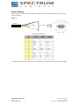
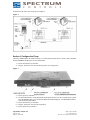
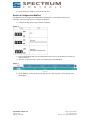
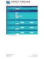
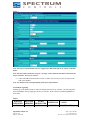
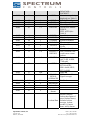
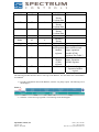
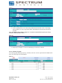
Technical Note
Title: Interfacing WebPort with Fireye Flame Monitor
Date: 7/28/08
Product(s): WebPort 500, 2001, 2005, 2101, 4001, 4005, 4101
Product Revision: 5.4s3 or later
Information: Communication is Modbus RTU
Document # TN072801-01
Section 1 Introduction
The Fireye flame monitor controller communicates Modbus RTU which makes it compatible with all
WebPort devices. The Fireye uses RS485 communication and acts as a Modbus RTU slave. The WebPort
must be configured for RS485 and Modbus Half-duplex to communicate with the Fireye controller.
Required Hardware:
•
•
•
•
•
•
WebPort (i.e. 500, 2001, 2005, 2101, 4001, 4005, 4101)
EB-700 Controller
EP160 Programmer
ED510 Display Module
ED580 Cable
ED512-4 Communication Cable
Optional Hardware:
•
ED610 Multi-port connector
Note: The Multi-Port connector is used to simplify wiring.
Reference Documentation:
•
•
•
•
WebPort User Manual
Fireye Bulletin E-8002
Fireye Bulletin EPMBUS
Fireye Bulletin EP-1601
Spectrum Controls, Inc
P.O. Box 5533
Bellevue, WA 98006
Phone: (425) 746-9481
Fax: (425) 641-9473
Web Site: www.spectrumcontrols.com
Section 2 Wiring
Take the ED512-4 and cutoff one of the RJ12 connectors. Make the following connects to a 9 pin female
D-shell connector:
Figure 1
ED512-4
(B –) Pin 8
(A +) Pin 3
WebPort Serial Port Pin
Connect the remaining RJ12 connector to one of the RJ12 ports located on the EP160 programmer module.
Spectrum Controls, Inc
P.O. Box 5533
Bellevue, WA 98006
Phone: (425) 746-9481
Fax: (425) 641-9473
Web Site: www.spectrumcontrols.com
If ED610 is used, follow the wiring shown in Figure 2.
Figure 2
Section 3 Configure the Fireye
The Fireye Modbus RTU unit address must be set. Follow the procedures below. Refer to Fireye bulletins
E-8002, EPMBUS and EP-1601 for more information.
1.) Power down the Fireye controller
2.) Flip the “check/run” switch to the check position. See image below.
Figure 3
3.) Power up Fireye controller.
4.) Use the SCRL button to scroll through the menu options until you see the “program setup” option.
Press the MODE button. The current unit address should be displayed. Use the RESET button to
select the desired unit address.
5.) Power down the Fireye controller.
6.) Flip the “check/run” switch to the run position.
7.) Power up the Fireye controller.
Spectrum Controls, Inc
P.O. Box 5533
Bellevue, WA 98006
Phone: (425) 746-9481
Fax: (425) 641-9473
Web Site: www.spectrumcontrols.com
8.) Verify that the unit address is set to the desired value.
Section 4 Configure the WebPort
The WebPort must be configured for Modbus RTU Half-Duplex to communicate with the Fireye
Controller. Follow the steps below to configure the WebPort.
1.) Configure the dip switches on the WebPort for RS485.
Figure 4
2.) Logon to the WebPort and go to the configuration menu. Refer to the WebPort user manual for
more information.
3.) Select the “IO Server Config” option. The following screen should appear.
Figure 5
4.) Select “Modbus” on the pull-down menu and press the “edit” hyperlink. The following screen
should appear.
Spectrum Controls, Inc
P.O. Box 5533
Bellevue, WA 98006
Phone: (425) 746-9481
Fax: (425) 641-9473
Web Site: www.spectrumcontrols.com
Figure 6
5.) Enter the following settings.
Spectrum Controls, Inc
P.O. Box 5533
Bellevue, WA 98006
Phone: (425) 746-9481
Fax: (425) 641-9473
Web Site: www.spectrumcontrols.com
Figure 7
Note: The com port of the WebPort must be configured for 4800 baud, data bits 8, stop bits 1 and Halfduplex.
Note: The Slave address field show in Figure 7 for Topic A must equal the unit address entered into the
Fireye Controller. See step 4 in section 3.
6.) Connect the DB9 end of the ED512-4 cable, created in section 2 above, to the serial port on the
front of the WebPort.
Note: You should see the serial light blinking on the front of the WebPort.
4.1 WebPort Tag Setup
Modbus tags in the WebPort must be created to read data from the Fireye controller. The following table
shows the Modbus memory mapping of the Fireye controller. Refer to the Fireye Bulletin EPMBUS for
more detail.
Table 1
HOLDING
REGISTER
40001
MESSAGE
ADDRESS
00
Spectrum Controls, Inc
P.O. Box 5533
Bellevue, WA 98006
WORD
REQUESTED
1-6
RESPONSE
STATUS
VALUE
83 (053H) = RUN;
Phone: (425) 746-9481
Fax: (425) 641-9473
Web Site: www.spectrumcontrols.com
40002
01
1
MSGN
40003
40004
40005
40006
02
03
04
05
1
1
1
1-3
GSTAT
TIMER
FLAME
LOGSTAT
40007
40008
40009
40011
06
07
08
10
1
1
2
2
INPUTS
OUTPUTS
SYSMINS
BNRMINS
40013
12
2
CYCLES
40015
40016
14
15
1
1-6
LOCKOUT
LOCKOUT
HISTORY
40022
21
1-2
DEVTYP
40023
22
1
AMPTYP
40024
40025
23
24
N/A
2
40027-40035
40036
26-34
35
N/A
6
40042
41
6
FLAME
SIGNAL
AVERAGES
Not Used
Most Recent
Lockout Data
2nd Most
Recent
Lockout Data
Spectrum Controls, Inc
P.O. Box 5533
Bellevue, WA 98006
202 (0CAH) =
LOCKOUT
Current message being
displayed (see Table 1)
Defines Timer Type
Time, Flame, Address
Flame Signal
Current logic module,
PURGE,
PTFI, AUTO (See
Table 2)
Input limits state
Output relays state
System on minutes
Burner on minutes
Completed Burner
Cycles
Stored Lockout Count
Last 6 Lockouts, first
word is most current
lockout
Programmer device
type, 5=EP, 6=EPD,
7=MicroM
Amplifier Type;
EUVS4=0C0H;
EIR1=0A0H; ERT1,
EUV1=090H;
Not Used
PTFI and Auto Flame
Signal Averages
Returns complete
lockout description of
stored lockout history.
Includes lockout
message, lockout
module, @ burner
hours, and @ burner
Phone: (425) 746-9481
Fax: (425) 641-9473
Web Site: www.spectrumcontrols.com
cycles
40048
47
6
40054
53
6
40060
59
6
40066
65
6
40072
71
1-3
40073
72
1-2
40074
73
1
3rd Most
Recent
Lockout Data
4th Most
Recent
Lockout Data
5th Most
Recent
Lockout Data
6th Most
Recent
Lockout Data
Input limits
and Expansion
Module
registers
Expansion
Module
(E300)
registers
Returns input limits
state and lower and
upper expansion
module (E300)
registers. See Table 3
Returns lower and
upper Expansion
module registers
Return only upper
Expansion module
register
The following procedure describes how to create tags in the WebPort. For more detail refer to the WebPort
User Manual.
1.) From the configuration menu in the WebPort, select the “Tag Setup” option. The following screen
should appear.
Figure 8
2.) Select the “Create New Tag” hyperlink. The following screen should appear.
Spectrum Controls, Inc
P.O. Box 5533
Bellevue, WA 98006
Phone: (425) 746-9481
Fax: (425) 641-9473
Web Site: www.spectrumcontrols.com
Figure 9
3.) Create a tag that points to one of the memory addresses listed in Table 1 above. The settings
shown in Figure 10, creates a tag called “Status1” that displays the current status of the Fireye
controller.
Note: The Modbus address 40001 in Figure 10. It correlates to the STATUS response of the Fireye
controller, outlined by Table 1 above.
Figure 10
4.) Repeat steps 1 through 3 to create the remaining tags for the Fireye controller.
4.2 View WebPort Tag Data
To view the tag data returned by the Fireye controller, select the “View IO” option from the WebPort main
menu. The following screen should appear.
Figure 11
Spectrum Controls, Inc
P.O. Box 5533
Bellevue, WA 98006
Phone: (425) 746-9481
Fax: (425) 641-9473
Web Site: www.spectrumcontrols.com