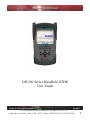
1
DR-500 Series Handheld OTDR
User Guide
© 2010 Advanced Fiber Solutions, Inc. All rights reserved – V-05
19 Norfolk Ave * Easton * MA * USA * 02375 - Phone: 508.238.7100 * Fax: 617.507.0784
1
Table of Contents I
1. General Information
2. Safety Information
3. Introduction
• Recommended Accessories
4. Unit Introduction
• Working Principle
• Technical Specifications
5. Getting Started
6. Customizing your OTDR
7. Working with the OTDR
8. Setting up Measuring Parameters
• Parameters
• Additional Measuring and Analysis Parameters
• Additional Parameters
• Trace View Parameters
9. Automatic Saving
10. Start Measurement
11. Working with Files
• Opening Trace Files
• Saving Trace Files
• Additional functions
12. To access the information window
• To Delete files
• To Copy and Paste
• To Open a File
13. Manual Measuring Modes
• Measuring Attenuation between two marker points - (2
PT)
• Measuring the Attenuation by Approximation - (LSA)
• Attenuation Measurement of an “Event” – (Splice)
• Reflective Coefficient Measurement - (Reflection)
• Optical Return Loss - (ORL)
• To Select a Particular Marker Method
© 2010 Advanced Fiber Solutions, Inc. All rights reserved – V-05
19 Norfolk Ave * Easton * MA * USA * 02375 - Phone: 508.238.7100 * Fax: 617.507.0784
2
Table of Contents II
14. Zoom/Scroll/Markers Controls
• Using Zoom Controls
• Using Scroll Controls
15. Events table
• Type of the event
• Working with events
• To Create Event
• To Remove Event
• To Move Event
16. Working with Traces
• Select Traces to Compare
• Automatic Trace Analysis
• Trace filtering
• Applying trace template
• Information about the Trace
• Changing Parameters for a Measured Trace
17. Communication with a PC
18. Optional Features – Power Meter/Light Source
19. Storage
20. Transportation
21. Warranty Certificate
22. Contact Information
© 2010 Advanced Fiber Solutions, Inc. All rights reserved – V-05
19 Norfolk Ave * Easton * MA * USA * 02375 - Phone: 508.238.7100 * Fax: 617.507.0784
3
General Information
Limited Warranty
12 Months From Original Factory Ship Date
All Advanced Fiber Solutions products are warranted against defective material
and workmanship for an period of 12 months from original factory ship date. Any
product found to be defective within the warranty period will be repaired or
replaced by Advanced Fiber Solutions. In no case will Advanced Fiber Solutions
liabilities exceed the original purchase price of the product.
Exclusions
The warranty on your equipment shall not apply to defects resulting from the
following
•
•
Misuse, negligence or accident.
Unauthorized repair or modification.
For full details of Advanced Fiber Solutions warranty, please visit
www.afsi.us
Or call 508-238-7100 for a copy of Advanced Fiber Solutions warranty.
© 2010 Advanced Fiber Solutions, Inc. All rights reserved – V-05
19 Norfolk Ave * Easton * MA * USA * 02375 - Phone: 508.238.7100 * Fax: 617.507.0784
4
Safety Information
Safety Information
Product Offering
Laser Class
Class 1 laser output
•
•
•
•
AF-DR-515
AF-DR-525
AF-DR-529
AF-DR-535
(850nm/1300nm)
(1310/1550nm)
(1310/1550/1625nm)
(850/1300/1310/1550nm)
Class II laser output – Do not stare at beam
•
VFL Port
Warning! When working with an OTDR, Never look or stare directly
into the optical outputs of fiber optic test equipment, patch cords or test jumpers.
Use of procedures or adjustments other than those specified herein may result in
hazardous radiation exposure. Optical radiation that is harmful to the eye may be
present. This may result in permanent eye damage. While the chances of such an
occurrence taking place is very unlikely, Advanced Fiber Solutions, Inc. still
strongly advises against this. Refer to your company’s safety procedures when
working with optical systems.
The DR-500 series Handheld OTDR contains no user serviceable parts. Except for
cleaning the optical port, this instrument must be returned to Advanced Fiber
Solutions, Inc. or an authorized agent for repair or calibration.
The unit corresponds to GOST 12.2.091 (IEC 61010-1), equipment class III. The
AC/DC adaptor corresponds to GOST 12.2.091 (IEC 61010-1), equipment class II.
© 2010 Advanced Fiber Solutions, Inc. All rights reserved – V-05
19 Norfolk Ave * Easton * MA * USA * 02375 - Phone: 508.238.7100 * Fax: 617.507.0784
5
Introduction
Thank You for purchasing Advanced Fiber Solutions, Inc. Optical Time Domain
Reflectometer. The purpose of this User Guide is to explain how to use and
maintain this OTDR. If you have any questions regarding your fiber optic
instrument or if you need technical or application support, please contact
Advanced Fiber Solutions, Inc. This manual includes the technical characteristics,
operating principles and operating procedures for the DR-500 Series Handheld
OTDR.
DR-500 Series Package Includes
•
•
•
•
DR-500 Series Handheld OTDR device
AC/DC adapter
Interface cable USB A – mini USB B
Storage Battery
•
•
•
OTDR PC Application Software CD
User Guide for OTDR and PC application
software
Carrying Case
Recommended Accessories
Fiber optic test cables (launch cables, pulse suppression cables, patch cords or
jumpers) to connect the fiber under test and the OTDR. The test cables must have
the same core and cladding size as the fiber under test.
A supply of optical cleaning pads, isopropyl alcohol or filtered compressed air is
recommended for cleaning the fiber optic connectors.
Important! Proper care in handling should be taken when using any precision
optical test equipment. Scratched or contaminated optical connectors can impact
the performance of the instrument. It is important to keep the optical ports
covered when the unit is not being used.
© 2010 Advanced Fiber Solutions, Inc. All rights reserved – V-05
19 Norfolk Ave * Easton * MA * USA * 02375 - Phone: 508.238.7100 * Fax: 617.507.0784
6
Unit Introduction
The unit is one of the most compact OTDR’s on the market today, idea for
handheld use and pocket transportation. The unit is light weight weighing less
than 1.6 Lbs. It is extremely rugged with a thick protective rubber boot
surrounding the outer case. It also offers a long battery life enabling the technician
to continuing test up to eight hours.
It is a full featured OTDR offering four different performance classes to choose
from, with a dynamic range starting at 23dB going up to 43dB. Class A is
optimized for private and premise networks. Class B is optimized for FTTx and
CATV networks. Class C is optimized for close event detection and large
attenuation measurements like PONS networks. Class D is optimized for long haul
applications.
Along with a wide dynamic range to choose from, the unit offers a number of
wavelength options for both single mode and multimode applications with single,
dual, tri and quad models available. Wavelength options include 850nm, 1300nm,
1310nm, 1550nm and 1625nm.
The unit is simple to operate and is the perfect installation, maintenance and link
trouble shooting tool. It is the ideal OTDR for either the inexperienced or the
experienced technician. The unit supports both a manual mode for the expert user
which enables parameter setup and an automatic mode for the less experienced
user which allows one touch auto run testing. The unit utilizes active sync for
seamless USB connectivity with desktop software for advanced data analysis and
storage capabilities.
It is fully compliant and compatible with the .sor file format outlined in the belcore
GR-196 OTDR data standardization document. Other optional features offered by
this industry leading OTDR include a built in power meter, light source and Visual
Fault Locator.
Product Highlights and Key Features
•
•
•
•
•
•
Compact and rugged case
Single, dual, tri and quad λ
models available
Events table and auto test
function
Up to 43dB Dynamic Range
Weight less than 1.6 lbs
Four performance classes to
choose from
•
Bellcore .sor format compatible
•
USB jump drive compatible for extra storage
•
9 hours of operation, fast charging Li-Ion battery
•
•
High contrast full color display
User friendly and easy too operate
•
Optional features: Power Meter and Light Source
© 2010 Advanced Fiber Solutions, Inc. All rights reserved – V-05
19 Norfolk Ave * Easton * MA * USA * 02375 - Phone: 508.238.7100 * Fax: 617.507.0784
7
Working Principle
The OTDR’s operating principle is based on the measurement of the Raleigh
Backscattering Signal, generated by sending a high power optical pulse from the
OTDR through the optical fiber. Light is reflected back to the OTDR. This
backscattered light is measured by the sensitive optic receiver, converted to digital
form and averaged to improve the signal to noise ratio. The resulting signal forms
a graph called a TRACE. The trace is a visual representation of the backscattering
coefficient created by the OTDR to determine the “events.” The trace shows the
“events” on the fiber optic link such as breaks, splice loss, bends, attenuation and
distance.
OTDR Distance Calculation Formula
Distance = c * t / ( 2 * n )
c = speed of light in a vacuum
n = index of refraction of the fiber under test
Time delay between pulse emitted
© 2010 Advanced Fiber Solutions, Inc. All rights reserved – V-05
19 Norfolk Ave * Easton * MA * USA * 02375 - Phone: 508.238.7100 * Fax: 617.507.0784
8
Technical Specifications
Class Definitions**
Class Definitions
Dynamic Range
Single mode
1310/1550/1625nm
Dynamic Range
Multimode
850/1300nm
Event Dead Zone
Both MM & SM
Attenuation Dead
Zone
Both MM & SM
Ax
A
31/29/28
dB
@20uS
A+
34/32/31
dB
@20uS
B
39/37/36
dB
@20uS
C
37/35/34
dB
@20uS
D
42/40/39
dB
@20uS
N/A
23/24dB
N/A
N/A
26/28dB
N/A
N/A
2.5 M
2.5 M
1.8 M
1.8 M
1.0 M
1.4 M
1.4 M
12 M
9.5 M
6.5 M
6.5 M
4.5 M
9.0 M
9.0 M
25/27dB
@20uS
D+
44/42/41dB
@20uS
All Units
Distance Range
Data Points
Loss Resolution
Distance Accuracy
Refractive Index Range
Language
OTDR Modes
Attenuation Measurement Accuracy
Sampling Resolution
Storage Capability
Unit Measurement
2,5,10,20,40,80,120,160,240 Km
Up to 64,000
0.001dB
±(0.5+5´10-5´L+( n/n)´L)
1.0000…..2.0000
English
Full Auto, Expert and Real Time
0.05dB
0.16m…..7.6m
~ 500 traces
Meter
Temperature Specifications
Operation Temperature
0°.. +40°C
Relative Humidity
95% Without Condensation
© 2010 Advanced Fiber Solutions, Inc. All rights reserved – V-05
19 Norfolk Ave * Easton * MA * USA * 02375 - Phone: 508.238.7100 * Fax: 617.507.0784
9
GETTING STARTED
Preparation for work
The device maybe operated when powered by the external 12V AC/DC adapter or
separately by the internal battery, once the battery is charged to an acceptable
operational level. If the unit is being charged by the external 12V power supply
both the green “BATTERY” LED and the orange “CHARGE” LED on the face panel
will illuminate. The fiber to be tested is connected to the OTDR’s optical connector
on the front panel of the unit. It is recommended to always use a launch cable
when using an OTDR but it is not necessary. If testing the cable directly with the
OTDR the cable connector style must match the OTDR output connector. Power
Meter optical port offers versatility with removable connector adapters. All OTDR
connector ports and test cables should be kept clean and free of dust and dirt for
optimal unit operation.
Powering On/Off unit
The unit is powered On or Off by pressing and holding the
button for several
seconds.
When the unit is powered on the green LED on the face panel will illuminate.
Menu Options
© 2010 Advanced Fiber Solutions, Inc. All rights reserved – V-05
19 Norfolk Ave * Easton * MA * USA * 02375 - Phone: 508.238.7100 * Fax: 617.507.0784
10
Keypad Options
Parent Buttons P, C and
P Button enables the technician to switch between currently activated menu to
Main menu.
C Button by default is an ESC key (escape or back) but it can also be used for
the following
• Stop a measurement when running.
• Reset to Main menu.
• Exit from dialog boxes and modes (for instance the Events table mode).
• Un-zoom/Reset zoom state of trace.
button as well being the key to turn the unit On and Off also has a software
assigned function and will show/hide a trace preview box in the right top area of
the screen when pressed.
© 2010 Advanced Fiber Solutions, Inc. All rights reserved – V-05
19 Norfolk Ave * Easton * MA * USA * 02375 - Phone: 508.238.7100 * Fax: 617.507.0784
11
Customizing your OTDR
The following features can be customized
on the DR-500 series unit.
• Keyboard
• Display
• Date/Time
To customize the device.
• Press P to access the Main menu.
• Press F4 (Device) to enter device
mode.
• Press F1 (System Setup) to
activate the setup window.
• Use the left/right arrow to choose
the desired icon in the window.
Keyboard Properties
•
•
•
Select the Keyboard icon and open
the keyboard properties window.
Use the up/down arrows to move
between the lines.
Use left/right arrows to change the values.
Tick the “Enable character repeat” check box to enable a continuous repeated
•
action when the desired button is continuously pressed.
Press C to close the window and save the changes.
•
Display Properties
•
•
•
•
Select the Display icon and open
the Display properties window
Use the up/down arrows to move
between selections.
Press Enter to enable any checkbox or show the list of values.
Press C to close the window and save changes.
© 2010 Advanced Fiber Solutions, Inc. All rights reserved – V-05
19 Norfolk Ave * Easton * MA * USA * 02375 - Phone: 508.238.7100 * Fax: 617.507.0784
12
Setting Date and Time
Note: When a trace is saved the device also
saves the corresponding time and date
•
•
•
•
•
Select the Date/Time icon and open the
Date/Time properties window.
Use the left/right arrows to move to the
next selection to be changed.
Use the up/down arrows to change values.
Press the P to move to between selection
options.
Press the C to close the window and save the changes.
Setting Language
• Select the Language icon and open the
Language properties window.
• Use up/down arrows to select the desired
language.
• Press C to close the window and save the
changes.
© 2010 Advanced Fiber Solutions, Inc. All rights reserved – V-05
19 Norfolk Ave * Easton * MA * USA * 02375 - Phone: 508.238.7100 * Fax: 617.507.0784
13
Working with the OTDR
Setting up Measuring Parameters
•
•
•
•
•
•
•
Press P to access the main menu.
Press F2 (Setup) to access the measuring
parameters window.
To move to desired parameter selection
use the up/down or left/right arrows.
Press Enter to activate the desired
parameter selection.
Use the up/down arrows to choose the
desired value. The value will become
highlight.
Press Enter to confirm changes.
Press C to close the window and save the changes.
Note:
1 Several wavelengths can be selected simultaneously. In this case measurements will
be performed on all chosen wavelengths one after another without stopping.
2 If an DR-500 Series is the quad OTDR model(for both Single mode and Multimode
applications) the choice of single-mode OTDR wavelength (SM1310, SM 1550 etc) will
automatically cancel out the choice of multimode OTDR wavelengths (MM 850,
MM1300) and vice versa.
© 2010 Advanced Fiber Solutions, Inc. All rights reserved – V-05
19 Norfolk Ave * Easton * MA * USA * 02375 - Phone: 508.238.7100 * Fax: 617.507.0784
14
Parameters
•
Wavelength - For Multimode 850nm or 1300nm and for single mode
1310nm, 1550nm or 1625nm.
• Distance Range, Km - The maximum value of the measured distance. The
value of the distance range should exceed the length of the line under test
by more than 20%.
• Pulsewidth, ns – This determines the value of the optical pulse duration.
The range of the acceptable optical pulse value is dependent on the chosen
Distance Range and is automatically limited by the OTDR program.
• Resolution, m – This determines the distance between two samples
(sampling intervals) of the trace. The value is dependent on the Distance
Range.
• Measurement Time, Min/Sec – This determines the duration of the
measurement process with averaging. Live mode performs fiber monitoring
in real time mode.
• High Resolution - In this mode the optical receiver bandwidth is increased.
Best used when testing a short cables and requiring excellent dead zone – do not use on
long fiber lengths than require high dynamic range.
Note: To have the unit Auto Select the parameters press Auto Setup. The program
will perform a short measurement on the connected fiber and automatically define the
optimal parameters for that fiber. The technician can then modify the parameters
manually if desired and run a measurement
© 2010 Advanced Fiber Solutions, Inc. All rights reserved – V-05
19 Norfolk Ave * Easton * MA * USA * 02375 - Phone: 508.238.7100 * Fax: 617.507.0784
15
Additional Measuring and Analysis Parameters
•
•
•
•
•
•
Press P to access the Main menu.
Press F2 (Setup).
Press F3 (Other Parameters) to activate the additional measuring
parameters window.
o Set Refractive Index for each OTDR wavelength.
o Set Backscattering Coefficient for each OTDR wavelength.
o Set automatic Analysis Threshold parameters.
Move to the desired parameter selection using the left/right arrows. Press
Enter to activate the selection.
Use the up/down arrows to choose the desired setting. Once highlighted
press Enter to confirm and change.
Press C to close and save changes.
Additional Parameters
•
•
•
Backscattering Coefficient, BC – represents the level of backscattering in
a particular fiber. It is used for Reflectance and ORL measurement and can
be obtained from the fiber manufacturer. This parameter value can be stored
for any saved trace.
Refractive Index – (also known as group index) is used to convert time to
distance. For precise distance measurement it is important that this value is
accurate and can be obtained from the fiber manufacturer. This parameter
value can be stored for any saved trace.
Automatic Trace Analysis Threshold – have the following selectable
features
o Splice Loss, LT – threshold of the event attenuation value in dB.
Events with attenuation value that exceeds the threshold value will be
shown in the Events Table.
o Reflectance, RT – threshold of the event reflectance value in dB. The
reflected event having a reflectance higher than the threshold value
are shown in the Events Table.
o End-of-Fiber, ET – threshold of the event attenuation value in dB for
defining the fiber end. The first event with an attenuation exceeding
the threshold value is defined during the automatic trace analysis as
an optical fiber end. All subsequent events will be ignored.
o Attenuation, CT – Attenuation coefficient threshold value of the
section in dB/km. Exceeding the attenuation coefficient threshold value
will mark the section with an * in the Event Table.
© 2010 Advanced Fiber Solutions, Inc. All rights reserved – V-05
19 Norfolk Ave * Easton * MA * USA * 02375 - Phone: 508.238.7100 * Fax: 617.507.0784
16
Trace View Parameters
•
•
•
Zoom coefficient selection – x1.1, x1.3, x2, x5 or x10.
Inverts color in trace window – changes the trace color for different
lighting environments.
Show grid scale values – Displays grid lines value.
Automatic Saving
The program enables the automatic saving of measured traces into the DR-500
Series memory immediately after a measurement completion. It is advisable to
use Auto-Saving option when measuring a large number of traces (like cable
cores) to collect data for post testing analysis.
Warning! To avoid unwanted file saving and flash memory overflow, Autosave option is
disabled when device is turned on.
•
•
•
•
Press P to access Main menu.
Press F2 (Setup) and enter parameters
field.
Press F3 (Other Parameters).
Press F2 (Autosave) to activate the
Autosave setup window.
o Press Enter to select or de-select
the Auto save check box.
o Use the up/down arrows to
choose the desired field. The field
will become highlight, press Enter
to activate it and change the value.
o Change the name of the template for auto saving in the “File name for
saving” field.
o To have the OTDR ask if a file should be saved upon competition of a
measurement select the “Inquire about saving” check box.
o The file path window allows the user to change the Auto save file
location.
o Press F3 (create folder) to create a new folder for the Auto save
location.
o Press C to quit the Auto save window and save settings.
© 2010 Advanced Fiber Solutions, Inc. All rights reserved – V-05
19 Norfolk Ave * Easton * MA * USA * 02375 - Phone: 508.238.7100 * Fax: 617.507.0784
17
Start Measurement
•
•
•
•
•
Press P to access the Main menu.
Press F1 (Run) when in the Main menu or F1 (Run) when in the Measuring
Parameters field to run a measurement. The measurement will operate
according to the values set in the Measuring Parameters window.
The green bar at the bottom part of the screen will indicate the time past for
the current measurement.
The green “Laser” LED on the face panel will be illuminated during a
measurement.
Press C to stop a measurement manually.
Working with Files
All traces are saved in memory in the BELLCORE version 2.0 format and have a
.sor file extension
DR-500 Series files can be opened in other OTDR software programs if the
program supports the .sor file format. If several wavelengths are measured
simultaneously all the traces are saved as a group. They will have the same
common part of the name with the wavelength value added to the name –
example afs_1310, afs_1550 e.t.c.
Opening Trace Files
The device can open up to four traces at a time –
an active trace and additional traces.
To open file
•
•
•
•
•
•
•
Press P to access the Main menu.
Press F3 (File) to enter the File window.
Use the up/down arrows to navigate
through the file list.
Use right arrow to open folders.
Highlight the required file.
Press F2 (Open) to open the file.
To open additional traces see “Select Traces to Compare”.
Note: If the measurement was performed on several wavelengths the user will be asked
to open all corresponding files.
© 2010 Advanced Fiber Solutions, Inc. All rights reserved – V-05
19 Norfolk Ave * Easton * MA * USA * 02375 - Phone: 508.238.7100 * Fax: 617.507.0784
18
Saving Trace Files
•
•
•
•
•
•
•
•
•
•
Press P to access Main Menu.
Press F3 (File) to enter File window.
Use the up/down arrows to navigate through
the file list.
If required press F3 (Create Folder) to create a
new folder.
Highlight the required file or folder to save it
and press F1 (Save) – the File name dialog box
will be opened.
Note: the file can be saved in .sor format or .pdf format.
Use arrows to enter the desired name for the trace.
Press F2 (Left) and F3 (Right) to navigate through the name.
Press F1 (Delete) to delete any letter.
Press C to save the trace or F4 (Cancel) to return to the File window without
saving.
Note: Highlighting the file will tell the program to use its name and location as a template
for a new trace.
Additional functions
To access additional functions press F4 (More). This menu enables the technician
to copy or delete the highlighted trace. It also allows access to the information
table of the highlighted trace.
To access the information window
•
•
•
Activate additional function window.
Use the up/down arrows to select and highlight a trace.
Press F1 (Information) to activate the information window.
Note: Data in the information window can not be modified.
To delete files
•
•
•
•
Activate additional function window.
Use the up/down arrows to select and
highlight a trace.
Press F2 (Delete) to remove the selected file
from the memory of the device.
Confirm the deleting process.
© 2010 Advanced Fiber Solutions, Inc. All rights reserved – V-05
19 Norfolk Ave * Easton * MA * USA * 02375 - Phone: 508.238.7100 * Fax: 617.507.0784
19
To Copy and Paste
•
•
•
•
•
Activate additional function window.
Use the up/down arrows to select and highlight a trace.
Press F3 (Copy) to copy the selected file/trace from memory.
Use the up/down and left/right arrows to select a location to copy to.
Press F3 (Paste) to paste a file to the selected location.
To Open a File
•
•
•
Activate File window.
Use the up/down arrows to highlight a
file/trace.
Press F2 (Open) to open the selected trace.
© 2010 Advanced Fiber Solutions, Inc. All rights reserved – V-05
19 Norfolk Ave * Easton * MA * USA * 02375 - Phone: 508.238.7100 * Fax: 617.507.0784
20
Manual Measuring Modes
Using the Markers
Measuring Attenuation between two marker
points - (2 PT)
In this markers mode values are shown at the bottom of
the screen in the horizontal information panel. The
measurement values are based upon where the left hand
marker (A) and right hand marker (B) are positioned on
the trace screen. The dB field in the information panel
displays the attenuation between the left and right hand markers, while the
dB/km field displays the attenuation coefficient.
Measuring the Attenuation by Approximation - (LSA)
The attenuation measurement by approximation mode is
used to measure “non- event” sections of the fiber optic
link. This mode increases the accuracy of the attenuation
measurement between the two markers by using a
straight line to approximate the measurement. The
approximation straight-line measurement values are
shown at the bottom of the screen in the horizontal
information panel. The measurement values are based
upon where the left hand marker (A) and right hand marker (B) are positioned on
the trace screen. The dB field in the information panel displays the attenuation
between the left (A) and right (B) hand markers, while the dB/km field displays
the attenuation coefficient.
Attenuation Measurement of an “Event” – (Splice)
Using the “Five Markers” method the OTDR measures the
attenuation of a specific event. The “five marker” method
works as follows
The left marker (A) and right marker (B) are placed on
either side of the event, as close as possible to the edges
of the event, without touching the event itself. The two
outermost markers (a and b) are used to calculate the
straight line approximation of the fibers on both sides of
the event and the fifth marker (c) is used to locate the begining of the event. The
measurement results are displayed in the horizontal information panel. The Spl,
dB field in the information panel displays the attenuation of the event while the
Spl, km field displays the distance to the event being tested (middle marker).
© 2010 Advanced Fiber Solutions, Inc. All rights reserved – V-05
19 Norfolk Ave * Easton * MA * USA * 02375 - Phone: 508.238.7100 * Fax: 617.507.0784
21
Reflective Coefficient Measurement - (Reflection)
This marker method is used to measure the reflection
coefficient of a specific connector event. Place the right
marker (B) on the peak of the reflected event. Place the
left marker (A) on the base line of the trace directly
before the event. The measurement results are displayed
in the horizontal information panel. The Refl, dB field
displays the reflective coefficient between markers A and
B while the Refl, km field displays the left (A) marker
and location of the base of the connector.
Optical Return Loss - (ORL)
This marker method measures the Optical Return Loss of a partial fiber section or
the whole fiber link
Place the left (A) and right (B) markers on the fiber link that is being tested. The
measurement results are displayed in the horizontal information panel. The dB
field in the information panel displays the attenuation between the left (A) and
right (B) hand markers while the ORL, db field displays the ratio (in dB) of the
optical power entered into the fiber link verses the power which is returned to the
beginning of the fiber.
© 2010 Advanced Fiber Solutions, Inc. All rights reserved – V-05
19 Norfolk Ave * Easton * MA * USA * 02375 - Phone: 508.238.7100 * Fax: 617.507.0784
22
To Select a Particular Marker Method
•
•
•
•
•
Enter the trace screen and menu.
Press F1 (Markers) to select a particular marker method (2PT, LSA, Splice,
Reflection or ORL)
Use the up/down arrows to highlight a desired markers setting.
Press Enter to select the marker setting.
A pop up window indicates which markers are currently active.
Note: If a marker is moved too close to another, both will move together to ensure
minimal distance between each marker. Marker can be moved separately or all together
simultaneously. At the top of each marker there is a distance position value in kilometer
with respect to the beginning of the optical fiber.
Zoom/Scroll/Markers Controls
Using Zoom Controls
•
•
•
•
•
Enter the trace screen and menu
Press F2 (Zoom/Scroll) to activate the
Zoom/Scroll mode. A magnifying glass icon
with direction arrows will appear on the screen.
Press Enter to choose the desired zoom mode
(horizontal, vertical or both).
Use the left/right arrows to move the
magnifying glass icon to the area where you
want to adjust the zoom.
Use the up/down arrows to zoom in or out on the trace.
Using Scroll Controls
•
•
•
•
Enter the trace screen and menu.
Press F2 (Zoom/Scroll) to activate the Zoom/Scroll mode.
Press Enter several times to choose the Scroll mode.
Use the left/right and up/down arrows to move the trace horizontally or
vertically.
Note: The scroll function is only available after zooming. In the Zoom/Scroll mode the
markers are inactive. While in the trace window the power button will activate a preview
window. The visual part of the trace will be marked with a dotted line. Press the power
button again to hide this window.
.
© 2010 Advanced Fiber Solutions, Inc. All rights reserved – V-05
19 Norfolk Ave * Easton * MA * USA * 02375 - Phone: 508.238.7100 * Fax: 617.507.0784
23
Events table
The Events Table displays all the events found by the
auto trace analysis feature.
• Enter the trace screen and menu.
• Press F3 (Table) to open the Events Table.
• Use the up/down arrows to navigate through
events list. Highlight events will be marked on the
trace.
• Press Enter to zoom in on a highlighted event.
• Press C to exit and hide the Events Table.
Note: User can still continue working with the trace while in the Event Table mode. F keys
enabled functions include moving markers, zooming and scrolling.
Type of the event
•
•
R – depicts an event with “reflection” once the reflection coefficient is higher
than the set threshold value irrespective of the attenuation in the event.
S - depicts an event “without reflection” once the attenuation coefficient is
higher and the reflection coefficient is lower than the set threshold values
© 2010 Advanced Fiber Solutions, Inc. All rights reserved – V-05
19 Norfolk Ave * Easton * MA * USA * 02375 - Phone: 508.238.7100 * Fax: 617.507.0784
24
Working with events
To Create Event
• Make sure that the trace menu is active and the Events Table is open.
• Press F4 (More) to activate Create, Delete and Move events menu.
• Use up/down arrows to zoom to required location.
• Move the markers to the required location for event to be created.
• Press F1 (Create Event) to create a new event in the Events Table.
To Remove Event
• Make sure that the trace menu is active and the Events Table is open.
• Use the up/down arrows to highlight the required event to delete from the
Events Table.
• Press F4 (More) to activate Create, Delete and Move events menu.
• Press F2 (Delete event) to remove the event from the Events Table.
To Move Event
• Make sure that the trace menu is active and
the Events Table is open.
• Use the up/down arrows to highlight the
required event to be moved.
• Press F4 (More) to activate Create, Delete and
Move events menu.
• Press F3 (Move Event) to activate the edit
mode.
• Press Enter to select the required marker.
• Use the left/right arrows to set the markers to appropriate position.
© 2010 Advanced Fiber Solutions, Inc. All rights reserved – V-05
19 Norfolk Ave * Easton * MA * USA * 02375 - Phone: 508.238.7100 * Fax: 617.507.0784
25
Working with Traces
•
•
•
•
•
•
•
Select Traces to Compare
Enter the trace screen and menu.
Press F4 (Traces) to activate the trace list.
Use the up/down arrow to highlight the
desired trace.
Press Enter to select the highlighted trace.
Four traces can be selected at once.
When a trace is highlighted the right arrow
allows the technician to make that trace the
“active trace” which will be indicated be the ∼
symbol next to it.
Press F3 (Delete trace) to remove a trace from the list.
Press C to close the window.
Note: The trace list can contain no more than 12 traces at a time. When a new trace is
opened and added to the list the last trace will be pushed off the list and removed. A
previously measured trace that is on the list can be saved once it is the “active” trace.
Automatic Trace Analysis
Auto trace analysis performs the following operations.
• It will search for events – with attenuation or reflection coefficient that
exceeds defined threshold values.
• Defines the distance to the event and the attenuation coefficient of the
section between the events.
• The acquired data analysis is then stored in the Events Table and with
corresponding marks highlighted on the trace.
• A previously marked trace events will be removed from the trace when
automatic analysis is applied.
To perform auto trace analysis on a trace
• Enter the trace screen and menu.
• Press F4 (Traces) to activate the trace list.
• Use the up/down arrow to highlight the desired trace.
• If required change the threshold parameters for the active trace – (see
Changing Parameter for a Measured Trace).
• Press F1 (Apply analysis) to apply auto analysis to trace. Wait a few
seconds.
• After analysis is finished the results can be viewed in the events table.
Note1: The option to Apply analysis after measurement immediately after completing
a measurement is available under the Setup window/Additional Parameters section.
© 2010 Advanced Fiber Solutions, Inc. All rights reserved – V-05
19 Norfolk Ave * Easton * MA * USA * 02375 - Phone: 508.238.7100 * Fax: 617.507.0784
26
Note2: On long fiber links when distant trace sections are distorted by noise, the
automatic analysis feature can be inaccurate, e.g. splices with low attenuation may
remain unrecognized in the noise background. These sections should be analyzed
“manually” utilizing such features as moving, deleting and creating events described
earlier.
Trace filtering
The program provides the option to apply a smoothing digital filter to the trace
after a measurement is acquired.
• Enter the trace screen and menu.
• Press F4 (Traces) to activate the trace list.
• Use the up/down arrow to highlight the desired trace.
• Press F2 (Apply filter) to apply the filter to the selected trace.
• To cancel the filtering effect Press F2 ( Unapply filter).
Note: The degree of filtering depends on the duration of the probe pulse.
Applying trace template
This is an important feature when testing multi-fiber
cables with multiple events. It allows the technician to
certify and analyze the fiber link quickly and easily with
the use of the Template. It will transfer the events of
one cable onto another cable.
To activate the Template Feature
•
•
•
•
•
•
•
•
•
Open a trace that has the desired event locations.
Make sure that the event locations are accurate and in the desired position
before using these events as the template.
The trace menu should now be present – if not press P to activate the menu.
Press F4 (Traces) to activate the trace list.
Use the up/down arrow to highlight the desired trace.
Press F4 (More) to activate additional trace menu.
Press F1 (Create template) to create a template based on the selected trace.
The pop up “Template is Created” will appear.
Press C to close the window and go back to the trace. Newly created events
will be listed in the Events Table.
Note: After applying template the previously created events will be removed.
© 2010 Advanced Fiber Solutions, Inc. All rights reserved – V-05
19 Norfolk Ave * Easton * MA * USA * 02375 - Phone: 508.238.7100 * Fax: 617.507.0784
27
Information about the Trace
Each trace has an information panel with the option to add additional operating
information.
To access the panel
• Enter the trace screen and menu.
• Press F4 (Traces) to activate the trace list.
• Use the up/down arrow to highlight the desired
trace.
• Press F4 (More) to activate additional trace
menu.
• Press F3 (Information) to open the information
panel.
• Use the left/right arrows to navigate between tabs.
• Use the up/down arrows to navigate between text windows.
• Press Enter to enter or modify text in the General Tab.
• Press C to close the window and save the information.
Changing Parameters for a Measured Trace
Once in the information panel the technician has the option to change the trace
parameters (Analysis Thresholds, Backscattering Coefficient and Refraction Index)
•
•
•
•
•
•
•
•
•
•
Enter the trace screen and menu.
Press F4 (Traces) to activate the trace list.
Use the up/down arrow to highlight the desired
trace.
Press F4 (More) to activate additional trace
menu.
Press F3 (Information) to open the information panel.
Press F1 (Analysis thresholds) to change automatic analysis thresholds.
Press F2 (Change BC) to change the back scattering
coefficient.
Press F3 (Change refindex) to change the refraction
index value.
Use the left/right and up/down arrows to modify
the values.
Press Enter to close the window and save the
changes.
© 2010 Advanced Fiber Solutions, Inc. All rights reserved – V-05
19 Norfolk Ave * Easton * MA * USA * 02375 - Phone: 508.238.7100 * Fax: 617.507.0784
28
COMMUNICATION WITH A PC
Compatible PC Software includes the following features
•
•
•
Device operational control features.
Trace analysis and PC storage.
Enables data transfer to and from the device via the USB port.
The CD software folder includes the following files and folders
• ActiveSync containing the files for Microsoft ActiveSync program.
• Software Package compatible PC software for controlling the DR-500
series unit, data analysis and data storage functionality.
To Connect the Device to PC software
• Switch on the device.
• Insert a CD into PC disk drive.
• Install the program Microsoft ActiveSync
(XP) or Mobile Device Center (Vista,
Win7).
• Connect the device to PC via the USB-A
to USB-B cable.
• ActiveSync will propose a partnership
when loaded – answer NO.
Transferring Files to PC
•
•
•
•
Switch on the device.
Connect the device to PC via the USB-A
to USB-B cable.
Once the unit has established a
connection with the PC the DR-500 file
Browser will be activated.
This Browser will enable the user to
connect and launch the AFS Reflect
OTDR software, transfer files to the PC,
copy files or load files directly to the Reflect platform.
© 2010 Advanced Fiber Solutions, Inc. All rights reserved – V-05
19 Norfolk Ave * Easton * MA * USA * 02375 - Phone: 508.238.7100 * Fax: 617.507.0784
29
Optional Features – Power Meter & Light Source
The unit also offers the optional features of both a power meter and laser light
source.
To enter the Power Meter and Laser Light Source mode
press the F4 button “Device” when in the main menu.
This will open the device menu as shown here.
To enter the Power Meter and Laser Light Source field
press the F4 button “Power Meter” again.
This will open the Power Meter and Laser Light Source
field as shown here.
To select a specific wavelength press the F1 button
“Wavelength”. This will enable the user to scroll to the
desired wavelength and select that wavelength by hitting
the return key. Selectable wavelengths include
650/850/1310/1490/1550/1625nm
F3 “Reference Level” enables the user to display the
reference level, enter a specified reference value or “fix”
use the current dBm level as a zero reference value by
scrolling to the desired option and hitting the return key.
F4 “Light Source” enables the user to turn the 1310nm or
the 1550nm light source on or off. Both wavelengths
have two transmitting options either CW(constant wave)
or 2Khz mode.
• ON CW mode
• ON* 2Khz Mode
© 2010 Advanced Fiber Solutions, Inc. All rights reserved – V-05
19 Norfolk Ave * Easton * MA * USA * 02375 - Phone: 508.238.7100 * Fax: 617.507.0784
30
STORAGE
Optical connectors on the device should be periodically cleaned to prevent any
contamination like dirt or dust. It is recommended to use specialized cleaning
products to clean optical plugs and ports.
When charging the DR-500 Series OTDR use the provided AC/DC 12V 2Amp
adapter. The battery will continue to charge whether the unit is powered on or off.
A fully charge of a discharged battery will take 3 hours. There is a slow discharge
when the unit is powered off so it is recommended that the battery be charged
every 25…..30 days.
Storage Specifications
Before unit is unpacked and opened
• Ambient temperature 5 to 40 °С
• Relative ambient air humidity up to 80% at 35 °С.
After unit is opened
• Ambient temperature 10 to 35 °С
• Relative ambient air humidity up to 80% at 25 °С.
Store in safe area clear of dust, acid vapor, alkali or gases that could can
corrosion.
TRANSPORTATION
The DR-500 Series OTDR, as packed by the manufacturer, can be transported in
closed-type vehicles of any kind [by rail, by truck/car, by river (in holds)]. When
transported by air the instrument should be placed in a heated airtight
compartment.
When transporting the packed instrument, all attempts should be made for the
DR-500 Series OTDR to be kept within the following limits
• Ambient temperature ranging from -20°C to 50° C
• Relative ambient humidity up to 95% (at 35°C)
The arrangement and fixation of packed instruments should be in compliance with
the normative and technical documentation applicable to the vehicle used.
If the instrument was transported, as packed by the manufacturer, at sub-zero
temperatures, after the transportation it should be left unpacked for two hours.
© 2010 Advanced Fiber Solutions, Inc. All rights reserved – V-05
19 Norfolk Ave * Easton * MA * USA * 02375 - Phone: 508.238.7100 * Fax: 617.507.0784
31
Warranty Certificate
Advanced Fiber Solutions, Inc warrants that its products sold by it to purchaser
will, upon delivery to purchaser, be free of defects in workmanship or materials
and will conform and function in accordance with the specifications for the product
as published by Advanced Fiber Solutions, Inc and in effect at the time of delivery.
Should any failure to conform to this warranty become apparent during the oneyear period after date of delivery of the product to purchaser, AFS will, upon
prompt written notice form the purchaser, correct such non-conformity by repair
or replacement at AFS’s Boston, Massachusetts facilities, shipment to such facility
to be at purchaser’s cost and repaired or replaced components to be shipped to
purchaser FOB AFS’s facility in Easton, Massachusetts. Correction in the manner
provided herein shall constitute a fulfillment of all liability of AFS with respect to
the quality of any products sold by it to purchaser.
THE FORGOING WARRANTY IS EXCLUSIVE AND IN LIEU OF ALL OTHER
WARRANTIES OF QUALITY, WHETHER WRITTEN, ORAL OR IMPLIED (INCLUDING
ANY WARRANTY OF MERCHANTABILITY OR FITNESS FOR PURPOSE).
THE
REMEDIES PROVIDED HERIN SHALL BE THE PURCHASER’S SOLE REMEDY FOR
ANY FAILURE OF AN AFS PRODUCT TO COMPLY WITH THE WARRANTY
PROVISIONS HERIN, WHETHER CLAIMS BY THE PURCHASER ARE BASED IN
CONTRACT OR IN TORT, INCLUDING NEGLIGENCE.
In no event will the AFS product warranty extend to non-conformity in the
performance resulting from: improper or inadequate maintenance performed by
any person other then AFS; failure of performance or function caused by or
attributable to any associated or complimentary equipment not supplied by AFS;
modification of any AFS product or connection therewith or supplementary
equipment not supplied by AFS or not produced by it; operation of the product or
its use other then as provided by AFS; accident, disaster, transportation or neglect
or any other circumstance, agency or event beyond AFS’s control.
IN NO EVENT SHALL AFS BE LIABLE FOR SPECIAL OR CONSEQUENTIAL
DAMAGES SUCH AS, BUT NOT LIMITED TO, DAMAGE OR LOSS OF OTHER
PROPERTY OR EQUIPMENT, LOSS OF PROFITS OR REVENUES, LOSS OF USE OF
EQUIPMENT, COST OF CAPITAL, COST OF PURCHASED REPLACEMENT, OR CLAIMS
FOR SERVICE INTERUPTION.
The remedies of the purchaser set forth herein are exclusive and the liability
of AFS with respect to any contract or anything done in connection therewith, such
as the performance or breech thereof, or from sale, delivery, repair, or use of any
AFS product, whether in contract, in tort, on strict liability or otherwise, shall not
exceed the price of the equipment or part thereof on which such liability is based.
© 2010 Advanced Fiber Solutions, Inc. All rights reserved – V-05
19 Norfolk Ave * Easton * MA * USA * 02375 - Phone: 508.238.7100 * Fax: 617.507.0784
32
Advanced Fiber Solutions, Inc.
19 Norfolk Ave,
Easton, Ma, 02375, USA
508-238-7100
800-556-9313
Fax:617-507-0784
Issue 5.0 Copy right Advanced Fiber Solutions, Inc
Distributed by:
45 Beechwood Dr., North Andover, MA 01845
www.L-com.com
Fax: 978-689-9484
E-mail: [email protected]
Toll Free: 1-800-343-1455
© 2010 Advanced Fiber Solutions, Inc. All rights reserved – V-05
19 Norfolk Ave * Easton * MA * USA * 02375 - Phone: 508.238.7100 * Fax: 617.507.0784
33