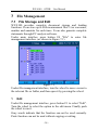
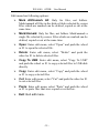
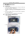
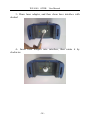
1
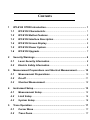
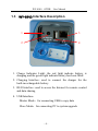
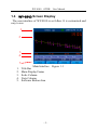
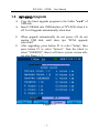
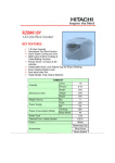
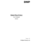
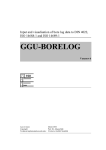
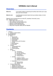
WY-8100 OTDR User Manual Ver1.00 NOTICE The information contained in this document is provided for the operation of WY-8100, WY-8100 is an Optical Time Domain Reflect-meter (OTDR), which is manufactured by Winyuan Technology Co., Ltd. The information contained in this manual is subject to change without notice. Winyuan shall not be liable for errors contained herein or for incidental or consequential damages resulting from the use of this material. This document must not be photocopied, reproduced, or translated into another language without the written consent of Winyuan. If someone need quote the information of this document, please give chapter and version for the document. Visual Conventions: In this document, we will use following sign. Information concerning the operation of WY-8100. I Important information concerning the correct operation of the WY-8100. Message warning the user of the risk of damaging the instrument or loosing information if the instructions are not respected. Message warning the user that he could be injured if the instructions are not respected. Laser Safety: WY-8100 contained 1310nm&1550nm semi-conductor laser, it’s governed by various safety regulations: Class 1 FDA21CFRξ1040.10 standard Class 3B IEC825-1(EN60825-1:1994) standard Warning labels: II Warranty: We guaranteed to keep WY-8100 in 12 months warranty period, but it didn’t contain any of following items: 1. Any malfunction arose by user’s incorrectness operation, if the user disobeys the rules of this document. 2. Open the shell without Winyuan’s permission. 3. Any malfunction arose by outside force, dipping in water, high temperature, low temperature, fire and so on. 4. Batteries. 5. The warranty period of lasers and APD is 12 months. III Contents 1 2 3 4 5 WY-8100 OTDR Introduction............................................................ 1 1.1 WY-8100 Characteristic ............................................................ 1 1.2 WY-8100 Button Features ......................................................... 3 1.3 WY-8100 Interface Description ................................................ 4 1.4 WY-8100 Screen Display .......................................................... 5 1.5 WY-8100 Power System ............................................................ 6 1.6 WY-8100 Upgrade ...................................................................... 7 Security Warnings ............................................................................ 8 2.1 Laser Security Information ...................................................... 8 2.2 Electric Safety Information ...................................................... 9 Measurement Preparations and Shortcut Measurement ............ 10 3.1 Measurement Preparations .................................................... 10 3.2 On-off ........................................................................................11 3.3 Shortcut Measurement ........................................................... 12 Instrument Setup ............................................................................ 13 4.1 Measurement Setup ................................................................ 13 4.2 Limit Setup .............................................................................. 14 4.3 System Setup .......................................................................... 16 Trace Operation .............................................................................. 17 5.1 Cursor Move ............................................................................ 17 5.2 Trace Zoom .............................................................................. 17 5.3 Trace Move .............................................................................. 18 5.4 Events Edit .............................................................................. 18 6 Events Analysis .............................................................................. 19 6.1 Trace Display and Event List ................................................. 19 6.2 Table Operation ....................................................................... 21 6.3 Event Analysis ......................................................................... 21 7 File Management ............................................................................ 24 7.1 File Storage and Edit .............................................................. 24 7.2 File Transfer............................................................................. 26 7.3 File Printing ............................................................................. 26 8 WY-8100 Maintenance .................................................................... 27 8.1 Cleanness ................................................................................ 27 8.2 Laser Interface Maintenance ................................................. 27 9 Problem and Fault Diagnosis ........................................................ 29 9.1 Instrument Problem ................................................................ 29 9.2 Measurement setup problem ................................................. 30 10 Key Technical Indicators ............................................................ 32 11 Standard Configuration .............................................................. 33 12 Guarantee .................................................................................... 34 12.1 General Information ................................................................ 34 12.2 Avoid Responsibility............................................................... 34 12.3 Service and Maintenance ....................................................... 34 13 After-sales Service Contact ....................................................... 36 I WY-8100 OTDR User Manual 1 WY-8100 OTDR Introduction WY-8100 is a portable stable and durable OTDR, which aims at testing fiber links. 1.1 WY-8100 Characteristic one key-press measurement and one key-press storage shortcut key design, one key-press setup smart portable OTDR, large colorized LCD screen firm, durable, shock-proof, moisture-proof large storage capacity, maximum store up to 800 measurement files built-lithium batteries, more than 10 hours working hours support USB and network interface, more convenient to manage files Front panel: -1- WY-8100 OTDR User Manual -2- WY-8100 OTDR User Manual 1.2 WY-8100 Button Features Button On-off: press to boot, once again press to close Shortcut Key: including file storage, wavelength setup, range setup and pulse width setup Auto Measurement: instrument will select the optimal settings automatically for measurement Manual Measurement: to setup by hand for measurement Character Keys: ESC——exit current state Character Keys——to input letters and numbers Function Buttons: including F1, F2, F3, F4, they correspond to the software buttons Enter: turn the wheel to select direction, press the wheel to enter -3- WY-8100 OTDR User Manual 1.3 WY-8100 Interface Description 1 3 2 4 1. Charge Indicator Light: the red light indicate battery is charging and the green light indicate battery has been filled 2. Charging Interface: used to connect the charger for the built-in rechargeable battery 3. RJ45 Interface: used to access the Internet for remote control and data sharing 4. USB Interface: Master Mode:for connecting USB to copy data Slave Mode:for connecting PC to system upgrade -4- WY-8100 OTDR User Manual 1.4 WY-8100 Screen Display The user interface of WY-8100 is as follow. It is customized and easy to use. 1 2 3 4 5 1. 2. 3. 4. 5. Main Interface Title Bar Main Display Frame Scale Column Note Column Software Button Area -5- Figure 1.1 WY-8100 OTDR User Manual 1.5 WY-8100 Power System WY-8100 use following powers: AC Adapter/Charger (connected to the standard power outlet) Li-ion Battery (supply power automatically when disconnected the AC adapter/charger) charge automatically adapter/charger Rechargeable Batteries: using Li-ion Battery with a long continuous power supply capacity, on normal condition it can continuous work for more than 10 hours after being fully charged. This performance is the best among currently all OTDR products on the market. when connected AC Li-ion Battery pack is light, safe and reliable. It can be charged and discharged more than 300 times with proper use. Must charge Li-ion Battery with the charger that we provide, otherwise the battery pack may be damaged. In low temperature case, the discharge capacity of Li-ion battery will deteriorate. When use it at low temperatures, its time of power supply will be shorter. In the limit case, it may be less than 30% at room temperature. -6- WY-8100 OTDR User Manual 1.6 WY-8100 Upgrade Copy the latest upgrade program to the folder "card" of USB disk. Insert USB disk into USB Interface of WY-8100 when it is off. It will upgrade automatically when boot. When upgrade automatically, do not power off, do not unplug USB disk, until show tips "FPGA upgrade successful" After upgrading, press button F1 to select "Setup", then press button F3 to select "System". Turn the wheel to select "VERSION", then it will show system version info, see also Figure 1.2. Figure 1.2 -7- WY-8100 OTDR User Manual 2 Security Warnings 2.1 Laser Security Information The OTDR laser interface and end of pigtail can be in front of people’s eyes on no condition. Otherwise, It may damage vision, even blindness! OTDR using high-power semiconductor laser, its high power sufficient to hurt people’s eyes, so must pay great attention. The correct way is that firstly take off the cap of OTDR laser interface on condition of power off, then connect fiber and boot OTDR to measure. After measurement, firstly off OTDR, then disconnect fiber, finally take off the cap of OTDR laser interface immediately. It should be noted that the pigtail, which will be connected to OTDR, must be clean. Forbid connecting fiber whose tie-in has grease. Otherwise, the instrument will not work properly. OTDR is engineering equipment. When used at the scene, it may be failed to connect because of dirt into tie-in of fiber, accordingly make the instrument not work properly. So must pay great attention. The correct way is: Before fiber is connected to the laser interface, its end should be cleaned by ethanol. After Alcohol is volatilized, the fiber can be connected to instrument. When fiber is taken off from instrument, the laser interface should be covered with the cap. -8- WY-8100 OTDR User Manual 2.2 Electric Safety Information The use of electrical equipment will be a serious security threat in the vicinity of flammable gases or fumes. In order to avoid electric shock, if any part of the appearance of instrument has been damaged, do not operate it. Only authorized personnel of our company can debug, maintain and repair a open live OTDR equipment. -9- WY-8100 OTDR User Manual 3 Measurement Preparations and Shortcut Measurement 3.1 Measurement Preparations Before the first use of the OTDR equipment, please charge the battery. When using OTDR equipment to measure, the operator should ensure that the type of fiber connector consistent with the equipment. Otherwise, it will lose accuracy of measurement. Generally, OTDR uses FC/PC fiber connector (jumper). Accordingly, operator should prepare measurement pigtails or adapters which match it. Usually, operator will face two situations. One is that measured-fiber has been installed and measured-side has been installed on the rack through some type of connector. In this case user should select FC/PC-XX/XX jumper to connect. FC/PC-side connects OTDR. XX/XX is the type of measured-fiber terminal adapter on the rack, such as FC/PC, FC/APC, SC/PC, SC/APC and so on. The other is that measured-fiber is a bare fiber. In this case user should use FC/PC bare fiber adapter or weld a jumper by themselves. Before using OTDR to measure, must prepare tools for cleaning the port, suggest that users prepare anhydrous alcohol, absorbent cotton or fiber cleaner. Otherwise, it will lose measurement accuracy, seriously will damage equipment. Suggest that users use an additional fiber to reduce dead zone. Any OTDR has measurement dead zone. If user is very interested in near end dead zone, they can use an additional length of fiber, whose length are known, to - 10 - WY-8100 OTDR User Manual "eliminate" dead zone. The length of additional fiber is determined by user’s experience. When using the measurement results, user should avoid this section of fiber. 3.2 On-off Press button on-off, immediately release the button after the on-off indicator light turn red, then OTDR equipment start booting. Press button on-off once again, a dialog box about off will appear. Choose off to off equipment, and choose cancel to maintain on-state. On on-state condition, press button on-off for seconds to forced off. - 11 - WY-8100 OTDR User Manual 3.3 Shortcut Measurement Press button "AUTO" directly after boot, WY-8100 will measure automatically. If users need to save results, press button "FILE" directly after measurement. This is the most efficient way for measurement, one key to measure, one key to store. If need to rapidly adjust the measurement parameters, press the shortcut key "WAVELENGTH" directly to change wavelength value between 1310nm and 1550nm; Press the shortcut key "DISTANCE" directly to change distance value; Press the shortcut key "PULSE WIDTH" directly to change pulse width value; See Figure 1.3. If want to measure completely by hand, see also Chapter 4. Then Press button "TEST" to measure. Figure 3.1 - 12 - WY-8100 OTDR User Manual 4 Instrument Setup If users want to enter measurement setup, push button F1 to select "Setup" (see also Figure 4.1). Then push F2 to enter limit setup interface (see also Figure 4.2), or push F3 to enter system interface (see also Figure 4.3), or push F4 to return. Figure 4.1 4.1 Measurement Setup Users can set measurement parameters by themselves in measurement setup menu. Measurement parameters comprise wavelength, distance range, pulse width, measure mode and acquisition time. The first three parameters can be also set by directly pressing shortcut keys. To set measurement parameters, turn the wheel to select parameter that you want to change, finally press the wheel to determine. The selected parameter is shown in red and indicated by arrow. - 13 - WY-8100 OTDR User Manual All gray word options indicate that they can not be selected. Input Acquisition Time: Turn the wheel, acquisition time is shown as Figure 4.4a. Push the wheel to make background of "minute" turn green, then input minute value through character keys, see also Figure 4.4b. Push the wheel again to make background of "ten second" turn green, then input ten second value through character keys, see also Figure 4.4c. Push the wheel again to make background of "second" turn green, then input second value through character keys, see also Figure 4.4d. Finally, push button "ESC" to finish it. Figure 4.4 4.2 Limit Setup 4.2.1 Index: Refractive index should be set correctly to ensure the accuracy of instrument range. General, system default, refractive index of 1310nm is set as 1.46600, refractive index of 1550nm is set as 1.46700. To set limit parameters, turn the wheel to select parameter that you want to change, finally press the wheel to determine. The selected parameter is shown in red. Select "INDEX", then push the wheel, then input numbers through character keys, finally push the wheel again to determine. - 14 - WY-8100 OTDR User Manual 4.2.2 Splice Limit: If select "Auto", instrument will show events that are in line with splice limit according to default value. If users set a value by themselves, only events larger than this threshold will be displayed. Input method is same as 4.2.1. 4.2.3 Slope Limit: If select "Auto", instrument will show events that are in line with slope limit according to default value. If users set a value by themselves, only events larger than this threshold will be displayed. Input method is same as 4.2.1. General, system default, slope of 1310nm is set as 0.33dB/Km, slope of 1550nm is set as 0.19dB/Km. 4.2.4 Reflectivity Limit: If select "Auto", instrument will show events that are in line with reflectivity limit according to default value. If users set a value by themselves, only events larger than this threshold will be displayed. Input method is same as 4.2.1. 4.2.5 Fiber End Limit: If select "Auto", instrument will select fiber end event that are in line with fiber end limit according to default value. If users set a value by themselves, only reflection events larger than this threshold will be selected as fiber end. Input method is same as 4.2.1. Figure 4.2 - 15 - WY-8100 OTDR User Manual 4.3 System Setup On system setup menu, turn the wheel to select the option, and then push the wheel to determine. To input numbers, directly push character keys. Figure 4.3 Let brightness value been low to save power. Turn up brightness value to make screen brighter with consuming more power. Turn the wheel to change brightness value, and do not support inputting numbers directly. Run automatic modification to up test speed on condition that instrument need to be adjusted because of long time using, or in environment that temperature changes dramatically. - 16 - WY-8100 OTDR User Manual 5 Trace Operation To enter trace analysis mode, press button F2 to select "Curve", see also Figure 5.1. Figure 5.1 5.1 Cursor Move WY-8100 provides a cursor L and a cursor R. Press button F1 to switch to left cursor, right cursor or double cursor. Turn the wheel to move the selected cursor. There are parameters below. Move single cursor to a certain point, and then zoom in to observe the details of trace near by; Observe distance, loss and slope between two points by double cursor. 5.2 Trace Zoom WY-8100 provides two “Zoom” modes: horizontal and vertical. Press button F2 to switch to horizontal zoom or vertical zoom, and then turn the wheel to zoom in and out traces. Zoom in and out base on the currently active cursor. - 17 - WY-8100 OTDR User Manual Press the wheel while zooming, trace will automatically return to full screen display status. 5.3 Trace Move WY-8100 provides two trace move mode: horizontal and vertical. To move trace, press button F3 to switch to horizontal move or vertical move, and the turn the wheel to move trace according to current zoom grade. 5.4 Events Edit WY-8100 provides events editing features, see also Figure 5.2. Figure 5.2 Add Events: Add a event on position where the selected cursor is (default left cursor when double cursor). Select event type, and then press the wheel to determine. :Non-reflective Event :Gain Event :Reflection Event :Fiber End Delete Events: Delete the event that is nearest to selected cursor. - 18 - WY-8100 OTDR User Manual 6 Events Analysis To enter event analysis mode, press button F3 to select "Event", see also Figure 6.1. After measuring, directly turn the wheel to switch among events. Press the wheel to see info of each event, press the wheel again to return. 6.1 Trace Display and Event List Instrument will show analysis results both in traces and event list after measuring. The events, which are displayed in event list, are also shown on traces with number mark. Both Figure 6.1 - 19 - WY-8100 OTDR User Manual Table Figure 6.2 Event list closely relates to measurements. When making a new measurement, event list will be refreshed. When reflection events are saturated, the maximum will be shown with ">". This indicates that the actual value are larger than the shown value. For each event that is displayed in event list, following information will be shown: Type: please refer to 6.5 event analysis for details Number: OTDR distribute a serial number for each event Distance: give the distance from starting point to the event point by unit meter (1000 feet or mile) Loss: the loss of each event with dB as unit Reflectivity: the reflectivity of each reflection event based on fiber measurement Slope: the measured attenuation in each region of fiber with dB as unit (loss/distance) Section: the distance between two adjacent events with km as unit (1000 feet or mile) Total Loss: total loss from starting point to end point, including event point loss and continuous fiber loss - 20 - WY-8100 OTDR User Manual 6.2 Table Operation To show only event list, press button F2 to select "Table", see also Figure 6.2. To show trace and event list, press button F1 to select "Both", see also Figure 6.1. Turn the wheel to see all events. 6.3 Event Analysis Each type of events has its own related symbols: Non-reflective Event (for example: welding points) Figure 6.3 This type of event has characteristics of signal level sudden reduction of Rayleigh backscatter. There are discontinuous points on downward-sloping trace slope. This type of events is usually caused by welding points, macro or micro bend in fiber. If threshold values have been set, once the loss of some event exceeds this threshold in value, the value will be displayed in event list. - 21 - WY-8100 OTDR User Manual Gain Event (for example: reverse welding points) Figure 6.4 This type of events points out a welding point accompanied with obvious gain phenomenon. As a result of two parts of fiber have different characteristics at backscatter joint. Event list gives the loss of the event, but the value does not represent the actual loss of the point. Only by two-way fiber measurement and two-way analysis can obtain actual loss of the point. Reflection Event (for example: fiber unfixed connector) Figure 6.5 The peaks of trace indicate reflection events. They form because of sudden interruption of index of - 22 - WY-8100 OTDR User Manual refraction. Reflection events make a majority of energy that is launched to fiber reflected back to light source. If a reflection event has arisen, it indicates that there is a connector or mechanical connection at the point, even a bad welding point or crack. Generally, loss and reflectivity of reflection events will be given. When reflection peak reaches maximum value, its peak will be flattened because that detector is saturated. So its dead zone may increase. If threshold value is set, once exceed threshold value of reflectivity and connector, and this value will be displayed in event list. Fiber End Figure 6.6 This symbol indicates that there is no longer continuous fiber after the event point. The location of the event point indicates total length of entire optical cable. - 23 - WY-8100 OTDR User Manual 7 File Management 7.1 File Storage and Edit WY-8100 provides complete document storage and loading functions. It can store up to 800 measurement files. User can name, number and annotate for each trace. It can also generate complete statements through PC analysis software. Under main interface press button F4 "File" to enter file management interface. (as shown in Figure 7.1) Figure 7.1 Under file management interface, turn the wheel to move cursor to the relevant file or folder, and then open it by pressing the wheel. 1 Edit Under file management interface, press button F1 to select "Edit". Turn the wheel to select the option in the edit menu. Finally push the wheel to run it. Gray words indicate that the function can not be used currently. Paste function can not be used without copying or cutting. - 24 - WY-8100 OTDR User Manual Edit menu has following options: Mark All/Unmark All: Only for files, not folders. Mark/unmark all files in the disk or folder selected by cursor. Files which are marked can be deleted, copied or cut at the same time. Mark/Unmark: Only for files, not folders. Mark/unmark a single file selected by cursor. Files which are marked can be deleted, copied or cut at the same time. Open: Enter edit menu, select "Open" and push the wheel or F1 to open the selected file. Delete: Enter edit menu, select "Delete" and push the wheel or F1 to delete selected files. Copy To USB: Enter edit menu, select "Copy To USB" and push the wheel or F1 to copy selected files to USB disk directly. Copy: Enter edit menu, select "Copy" and push the wheel or F1 to copy selected files. Cut: Enter edit menu, select "Cut" and push the wheel or F1 to cut selected files. Paste: Enter edit menu, select "Paste" and push the wheel or F1 to paste files that were copied or cut before. Exit: Quit edit menu. - 25 - WY-8100 1 OTDR User Manual Shortcut Key Storage Under main interface or file management interface, push shortcut store key directly to save current trace quickly. The store path is same as last time. Its file name number increment plus one. 1 Rename Under file management interface, press button F2 to select "Rename". And then Input the file name by pushing character keys. Finally, push the wheel or F1 to save a file to current selected folder with this name. 1 Create Dir Under file management interface, press button F3 to select "Create Dir". And then Input the folder name by pushing character keys. Finally, push the wheel or F1 to create a folder to current selected disk with this name. 7.2 File Transfer Insert USB disk into USB interface of WY-8100. Enter file management interface. Instrument will identify USB device automatically. See also Figure 1.2. Copy files to USB disk through edit menu. (see also chapter 7.1.1) A folder named "WY-8100" will be created automatically in root directory of USB disk. All files will be transferred to this folder. 7.3 File Printing Document printing can be carried out by computer analysis software. - 26 - WY-8100 OTDR User Manual 8 WY-8100 Maintenance 8.1 Cleanness Please keep OTDR equipment clean. Prevent oil, dust and other dirt to pollute the equipment. On relative humidity >90% condition should avoid using WY-8100. Avoid using WY-8100 through the rain or in water. Do not use organic solvent to clean the shell of equipment, use a dry cloth to do it. Please protect surface of equipment, avoid scratches. 8.2 Laser Interface Maintenance 1、Take off the cap 2、Rotate laser adapter by anti-clockwise - 27 - WY-8100 OTDR User Manual 3、Draw laser adapter, and then clean laser interface with alcohol 4 、 Insert laser adapter into interface, then rotate it by clockwise - 28 - WY-8100 OTDR User Manual 9 Problem and Fault Diagnosis 9.1 Instrument Problem 1 General Problem Problem: blank screen or fail to boot Possible Reason: battery has exhausted power Solution: charging the battery through making AC adapter/charger connect to an external power supply Problem: the screen is almost white or characters are fuzzy after boot Possible Reason: brightness settings are not correct Solution: enter setup interface to adjust brightness of screen 2 Fiber Connector Problems Measurement traces malfunctions caused by improper fiber connection show as follows: When measuring trace as shown in Figure 9.1, Figure 9.1 Possible Reason: ① use improper jumper interface ② connector is dirty ③ connector is aging - 29 - WY-8100 OTDR User Manual Solution : ① replace jumper ② clean the connector ③ replace the connector When measuring trace as shown in Figure 9.2, Figure 9.2 Possible Reason: ① unreliable connection ② connector deviate ③ positioning bolt deviate Solution: ① reconnect ② replace the connector 9.2 Measurement setup problem Problem: trace is too short and measurement time is too long Possible Reason: measurement distance range is set too long Solution: set proper distance range according to the actual length of fiber or the length measured through auto measurement mode Problem: show incomplete track, measurement failure Possible Reason: measurement distance range is set too short Solution: set measurement distance range greater than or equal to the actual length of fiber - 30 - WY-8100 OTDR User Manual Problem: measurement events are incomplete Possible Reason: pulse width is too large Solution: ① select a small pulse width ② increase measurement time Problem: trace noise is too large Possible Reason: pulse width is too small, not enough time to scan Solution: ① increase measurement time ② appropriately increase pulse width ③ set smoothing high - 31 - WY-8100 OTDR User Manual 10 Key Technical Indicators Module Specifications wavelength (nm) type WY-8100 dynamic range event dead (dB) zone (m) 1310±20/1550±20 30/28 <5m attenuation dead zone (m) <25m General Parameters distance range(Km) pulse width(ns) measurement time distance accuracy(m) attenuation accuracy loss limit(dB) loss resolution(dB) sampling resolution(m) sampling points data storage 5m-160km 5ns-10μ s user-defined(smart link) with real-time measurement function ±(0.5m ±0.001%×range + sampling resolution) ±0.01dB/dB 0.01dB 0.001dB 0.1m 64000 800 item Other Indicators LCD type laser adapter interface battery power operating temperature storage temperature relative humidity weight dimensions (mm) 4.0 inch TFT colorized LCD FC/PC USB、RJ45 built-in rechargeable Li-ion battery charging time <4 hours working time >10 hours AC/DC adapter input AC90-240V ±10% output DC18V 0℃~40℃ -10℃~50℃ <80% <1.5Kg 247×130×67mm - 32 - WY-8100 OTDR User Manual 11 Standard Configuration standard configuration OTDR AC-DC power adapter/charger user manual bag FC adapter CD - 33 - amount 1 1 1 1 2 1 WY-8100 OTDR User Manual 12 Guarantee 12.1 General Information WY-8100 products are guaranteed for 18 months since the date they are sold. But does not include following: Built-in Li-ion battery is not guaranteed. Laser sender and APD are guaranteed for one year. If replacing optical connector, which is bad because of improper usage, we will charge. 12.2 Avoid Responsibility Any malfunction due to wrong operation without complying with provisions of this manual. Warranty labels are tear up, malfunction because that the shell of equipments are open by non-authorized officer of our company. Malfunction due to the external mechanical force, such as liquid soak, heat, cold, fire and so on. Our company does not assume responsibility for damage due to usage, and malfunction because of connection to other equipment. Our company does not assume responsibility for damage of equipment, accessories and software due to improper usage or unauthorized modifications. 12.3 Service and Maintenance Send equipments to us for technical services or maintenance. 1. Please contact customer service center, technicians will determine whether your equipment need to be tested, repaired or calibration. 2. If possible, please backup your data before send it to us for repair. 3. If possible, please use original packaging materials to package equipment. Please attach a statement or report - 34 - WY-8100 4. 5. OTDR User Manual to explain malfunctions and phenomenon. Please pay freight and return equipment according to the address service personnel provide. After repaired, we will return equipment with a maintenance report. If the equipment is not within the scope of warranty, user should pay the costs noted in maintenance report. If within the scope of warranty, we will pay the return freight. Note: If the return equipment is in full compliance with all indicators after testing, all related costs are borne by the user. - 35 - WY-8100 OTDR User Manual 13 After-sales Service Contact Winyuan Technology Co., Ltd. Address: 8th Floor, Red Stone Business Building, 218 Chaowang Road, Hangzhou, China 310012 Http://www.winyuan.com Email: [email protected] [email protected] Tel: +86 571 88074976 Fax: +86 571 88074976 - 36 -