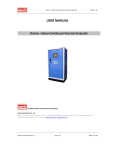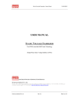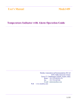
1
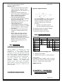
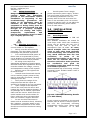
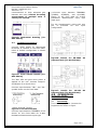
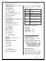
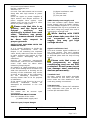
OPERATOR’S MANUAL
9000U ISOLATOR
Masibus Automation And Instrumentation Pvt. Ltd.
B/30, GIDC Electronics Estate,
Sector-25, Gandhinagar-382044, Gujarat, India
Ph: 91 79 23287275 - 79
Fax: 91 79 23287281, 82
Email: [email protected]
Web: www.masibus.com
masibus
Universal Linear Isolator 9000U
Ref No.: m92A/om/101
Issue No: 10
Note: Information in this manual is
subject to change without prior
notice or permission.
Contents
(1)INTRODUCTION
01
1.1
Purpose of The Manual
1.2
Product Over View / Description
1.3
Product Ordering Code
(2)SAFETY / WARNING
PRECAUTIONS
2.1
Safety Precautions
2.2
Warning Precautions
03
(3) INSTALLATION GUIDELINES 03
3.1
Mounting Details
3.2
Terminal Connections
(4) OPERATION GUIDELINE
4.1
Test Setup
4.2
Calibration Procedure
05
(5) APPLICATION
05
(6) SPECIFICATIONS
6.1
Input
6.2
Power Supply
6.3
Output
6.4
Isolation
6.5
Accuracy
6.6
Environmental
6.7
CMRR
6.8
NMRR
6.9
Mounting
6.10 Load Resistance
6.11 Size
06
(7)Trouble shooting
06
Figures & Tables
Figure 1: Signal Isolator
Figure 2: DIN RAIL Mounting
Details
Figure3: Mechanical Drawing
Figure4: Front Sticker Details
Figure5: Connection Details
Figure6: Details For 90-265
VAC Operated Unit
Figure7: Details For 18-36
VDC Operated Unit
Figure8: Test Set up
02
03
Table 1: Product ordering Code
Table 2: Output Loading Details
Table 3: Input/Output Range
02
06
08
04
04
04
04
04
05
Warning Symbol
The symbol calls attention to the
operating procedure, practice or the like
which if not correctly performed or
adhered to , could result in personal
injury or damage to or destruction of
part or all of the product and system. Do
not proceed beyond a warning symbol
until the indicated condition are fully
understood and met.
Class-2 Type of
instrument
Note: Class-2 – Instrument is
using Line & Neutral for Power
Supply Input.
Under absolutely no circumstances may
the contents of this manual, in part or in
whole, be transcribed or copied without
permission.
The contents of this manual are subject
to change without prior notice.
Every effort has been made to ensure
that the details of this manual are
accurate. However, should any errors be
found or important information be
omitted, please contact your nearest
Masibus representative or our sales
office.
1. INTRODUCTION
1.1.
Purpose of The Manual:
1.1.1.
How to read this
manual???
Installer: Read Chapters 1, 3, 7.
System Designer and New User:
Read All Chapters
Expert User: Read Chapters 4, 7.
1.1.2.
Regarding This
User’s Manual
Page 1 of 9
Universal Linear Isolator 9000U
Ref No.: m92A/om/101
Issue No: 10
→ This manual should be provided
to the end user. Keep an extra
copy or copies of the manual in a
safe place.
→ Read this manual carefully to
gain a thorough understanding of
how to operate this product
before starting operation.
→ This manual describes the
functions of this product. Masibus
does not guarantee the
application of these functions for
any particular purpose.
→ Under absolutely no
circumstances may the contents
of this manual, in part or in whole,
be transcribed or copied without
permission.
→ The contents of this manual are
subject to change without prior
notice.
→ Every effort has been made to
ensure that the details of this
manual are accurate. However,
should any errors be found or
important information be omitted,
please contact your nearest
Masibus representative or our
sales office.
1.2.
Description
1.2.1 The need for Isolation
Safety isolation is important for both
manufacturers and consumers. Its
purpose is to electrically separate
hazardous circuits and transient sources
from users and to protect products and
their surroundings. Galvanic isolation is
the most popular method. Transformers
and opto isolators are examples of
galvanic isolation. Transformers use
separate
windings
to
magnetically
convert power from inputs to outputs.
Opto isolators convert input signals into
light and then convert it back for the
output signals.
1.2.2 What Is Signal Isolator
masibus
Figure1: Signal Isolator
The Signal isolator is used to provide
galvanic isolation from one signal
(input) to another (output) and
usually combines the converter
function.
•
Isolator is normally used to
Provide isolation at three levels:
(a) Between Power to Input & Output
(b) Between Input to Output
(c) Between Output and output.
1.3.
Product Order Code
Model: 9000U
APS
Input Type
X
XX
C
4-20mA
U1
D
0-20mA
U2
E
1-5VDC
F
G
0-5VDC
010VDC
S
Special
No of O/P & type
X
90-265
VAC
18-36
VDC
X
1
One
1
4-20mA
2
Two
2
0-20mA
3
Three
3
1-5VDC
4
Four
4
5
0-5VDC
010VDC
S
Special
Table1: Product Ordering Code
X – Specify from table1
S – Specify from table 3, consult factory
For Example,
Universal Linear Isolator with 4-20mA
input & Dual output 4-20mA with 90-265
VAC aux. supply order code will be
9000-C-U1-2-1
2. SAFETY / WARNING
PRECAUTIONS
Page 2 of 9
Universal Linear Isolator 9000U
Ref No.: m92A/om/101
Issue No: 10
2.1. Safety Precautions
Dangerous voltages
capable
of
causing
death
are
sometimes
present in this instrument. Before
installation or beginning of any
troubleshooting
procedures
the
power to all equipment must be
switched off and isolated. Units
suspected of being faulty must be
disconnected and removed first and
brought to a properly equipped
workshop for testing and repair.
Component
replacement
and
interval adjustments must be made
by a company person only.
2.2. Warning Precautions
→
Before wiring, verify the label for
correct model no. and options.
→
Wiring must be carried out by
personnel, who have basic electrical
knowledge and practical experience.
→
It is recommended that power of
these units to be protected by fuses,
circuit breakers or external over current
rated at the minimum value possible.
→
All wiring must confirm to
appropriate standards of good practice
and local codes and regulations. Wiring
must be suitable for voltage, current,
and temperature rating of the system.
→
Beware not to over-tighten the
terminal screws.
→
Unused control terminals should
not be used as jumper points as they
may be internally connected, causing
damage to the unit.
→
Verify that the ratings of the
output devices and the inputs as
specified in Chapter 6 are not exceeded.
→
Upon receipt of the shipment
remove the unit from the carton and
inspect the unit for shipping damage. If
any damage due to transit, report and
claim with the carrier. Write down the
model number and serial number for
future reference when corresponding
with our Customer Support Division.
→
Do not use this instrument in
areas such as excessive shock, vibration,
dirt, moisture, corrosive gases or rain.
The ambient temperature of the areas
should not exceed the maximum rating
specified.
masibus
→
Provide power from a singlephase instrument power supply. If there
is a lot of noise in the power line, insert
an insulating transformer into the
primary side of the line and use a line
filter on the secondary side. As counter
measures against noise, do not place the
primary and secondary power cables
close to each other.
3.0 INSTALLATION
GUIDELINES
3.1. Mounting Details:
Universal Linear Isolator is DIN rail
mounting type.
Max ambient conditions are tested for
units kept under ideal test conditions,
where the air around the test unit is
moving and the unit is open to
atmosphere from all sides. In cases,
where multiple units are mounted
close to each other both vertically
and horizontally, the conditions are
very much different than the test
conditions,
in
terms
of
air
movement and ability of the unit to
shed out its internal heat. It is
therefore advised to make provision
for
ventilation
and
good
air
circulation inside the panel for long
and reliable operation.
Recommended way of mounting multiple
Universal Linear Isolator-9000U units is
shown below.
Figure2: DIN RAIL Mounting Details
[For DOP 55mm]
As air vents are provided on the top and
bottom part as shown in above figure of
the unit, the (horizontal) mounting
arrangement shown here, allows good
vertical air circulation. It is also
Page 3 of 9
Universal Linear Isolator 9000U
Ref No.: m92A/om/101
Issue No: 10
recommended to keep adequate gap
between two units. Vertical mounting
arrangement of multiple units is
strictly not advised.
masibus
**Connect input between TERMINAL
7(OPEN), 8(WIPER), and 9(CLOSE)
shown on the front label for 3-Wire
Resistance Measurement input type
input type.
For the potentiometric input type trim
pot
is
provided
for
the
input
configuration
Figure3: Mechanical Drawing [For
DOP 55mm]
3.2
Terminal Connection:
Connect rated power at appropriate
terminals as marked on the front label.
Label of default configuration is shown
below.
Figure6: Details For 90-265V
Operated Unit [For DOP 55mm]:
AC
Figure7: Details For 18-36V
Operated Unit [For DOP 55mm]:
DC
Figure4: Front Sticker Details [For
DOP 55mm]
The “ON” LED will glow when power is
applied to the unit. Connect Output-1
and Output-2 as shown here
Connect input between “IN+” and “IN-”
symbol shown on the front label.
4.0 OPERATION
GUIDELINES
4.1
Test Setup:
Turn on the equipment. Connect the
equipment as shown in figure.
*Short terminal 7 and 8.
Figure5: Connection Details
Connect input between TERMINAL 8 & 9
shown on the front label for 2-Wire
Resistance Measurement input type
Page 4 of 9
masibus
Universal Linear Isolator 9000U
Ref No.: m92A/om/101
Issue No: 10
CALIBRATOR
PRECISION
UNIT
DIGITAL
UNDER TEST
MULTIMETER
RESISTANCE
LOAD
Figure8: Test Setup
This equipment requires an external
power source, connect to an appropriate
source.
The Unit gives the output according the
Input feed from the appropriate source.
4.2
CALIBRATION PROCEDURE
Calibration for the unit should be carried
out by an experienced engineer only.
Equipment used for the calibration
should be of high accurate (0.05% or
better) and good stability.
Isolator output has to be calibrated at
two points: Zero (Desired O/P value at
minimum I/P value) at minimum Input
value and Span (Desired O/P value at
maximum I/P value) at full scale value.
For example: I/P is -1V to +1V and the
desired o/p is 4mA to 20mA. So first at
-1V I/P, O/P must be set to 4mA using
zero pot and after that at 1V I/P, O/P
must be set to 20mA using span pot.
In the calibration procedure the zero and
span of the unit needs to be calibrated.
There are two zero and two span pots,
one zero and span pot pair is for
trimming the output 1 of the unit and
another zero and span pot pair is for
trimming output 2 of the unit. For
calibration zero of output 1, set the
input at zero or minimum input, then
using the zero pot adjust the reading on
multimeter to 4.00mA, after that make
input at maximum (max. Input value)
and in this condition adjust the reading
on multimeter to 20.00mA using span
pot.
Check the zero again and repeat the
procedure until zero and span are
adjusted correctly. Now the zero and
span adjustment of the output 1 card
are calibrated. Similarly calibrate output
2 of the unit. Trim pots are identified by
“Z” for zero and “S” for span calibration
for both output separately. For checking
the Linearity takes reading in steps of
25%. Repeat the same procedure for
calibrating the other output.
Similarly for the potentiometric input
type the output has to be calibrated at
two points: Zero (Desired O/P value at
minimum I/P value) at minimum Input
value and Span (Desired O/P value at
maximum I/P value) at full scale value.
Variable Resistance Box can be used for
calibration
Note: For FOP calibrate output 3 & 4 of
the unit as per above calibration
procedure.
5.0
APPLICATION
Why Is Isolation So Important?
In most processes there are pieces of
electronic measurement and control
equipment from many different
manufactures. The signals from these
instruments are interconnected to each
other and to sensors, transducers and
output devices connected in the process
loop. In any such measurement and
control system there are several
problems that are likely to occur, all of
which can be solved by incorporating the
appropriate isolation between signals.
APPLICATION AREA:
A typical application could be where the
signal has to be distributed for indication
on local panel, field control room, main
control room and DCS system.
The Isolator provides a good protection
for sensitive system parts against
voltage spikes etc.
6.0 Specifications
6.1
Input:
Please Refer Sheet 1 attached at last
of this document. Note here any of
these
I/O
combinations
are
Page 5 of 9
Universal Linear Isolator 9000U
Ref No.: m92A/om/101
Issue No: 10
available with factory set. They are
not field settable.
Input Impedance:
For Current I/P 51Ω
For Voltage I/P ≥ 5 MΩ
6.2
Power Supply:
90VAC to 265VAC 45Hz to 65Hz Std.
18VDC to 36VDC on request.
Power Consumption:
Less than 10VA
6.3
Output:
Please Refer Table 3 attached at last
of this document.
Auxiliary Output:
Transmitter Power Supply 24VDC
Preferred Max load: 1.2KΩ
Max current Limit: 26mA Electronic
6.4
Isolation:
1.5KV AC between
Input to All Output
Output to Output
Input to Power
All Output to Power
6.5
Accuracy:
± 0.1% of FS
6.6
Environmental:
Humidity:
30 to 95% RH (Non-Condensing)
Ambient:
0 to 55 o C
Temperature Coefficient:
<100ppm
6.7
CMRR:
>100dB
6.8
NMRR:
>70dB
6.9
Mounting:
DIN RAIL (35 mm) Mounting
6.10
Load Resistance:
masibus
The table below shows corresponding
load according to current or voltage
ratings.
Load
Resistance
750Ω
910Ω
9.1KΩ
200Ω
1KΩ
2.7 KΩ &
more
O/Ps
0mA to 20mA and 4mA
to 20mA
-10mA to +10mA
-1mA to +1mA and 0mA to
1mA
0V to 1V,0V to -1V,-1V to
0V,1V to 0V,-1V to 1V
and 1V to -1V
0V to 5V, 0V to -5V, 5V
to 0V, -5V to 0V,-5V to
+5V and +5V to -5V
10V to 0V,-10V to 0V, 0V
to 10V, 0V to -10V, -10V
to 10V and 10V to -10V
Table2: Output Loading Details
6.11 Size:
Two Outputs:
45mm x 75mm x 110mm
55mm x 75mm x 110mm
Four Outputs:
100mm x 75mm x 110mm
7. TROUBLE SHOOTING
UNIT NOT TURNING ON
The problem can be bad connection /
power of incorrect rating.
First check, power on terminal of the
instrument itself if it is not present then
the fault is in power chord.
One must take care
while dealing with Power
wirings because it may
create electrical shock.
UNSTABLE READING
Check for loose connections.
First
verify
that
all
conventional
instrumentation
norms
have
been
followed for wiring. Try using shielded
cable for sensor input. Make sure that
the shield is connected to Earth ONLY at
Page 6 of 9
Universal Linear Isolator 9000U
Ref No.: m92A/om/101
Issue No: 10
one end. This cable should not be routed
along side with high tension or power
cables.
Check for ripple on power supplies of
Input section and Output sections. If
power supplies have ripples, input
voltage may be low or there is some
failure on power supply card.
Please note that this is an
isolator, and the Input and
Output
sections
are
electrically isolated from each
other. Therefore, any power
supply measurements should
be done with respect to
proper grounds.
OUTPUT NOT MATCHING WITH THE
EXPECTED VALUE
It is a normal tendency to doubt the
instrument performance, when the
Output is not matching the expected
value. Kindly make sure that the output
is really incorrect with respect to input
signal, before attempting any recalibration.
Account for measuring instrument’s
inaccuracies, lead errors and calibration
errors. Care must be taken when
measuring Output signal.
An ordinary 3½ digit multimeter is used
it can show reading which deviates from
what the instrument is showing as the
accuracy of the multimeter may not be
as good as the that of the instrument.
So
use
calibrating
instrument
of
accuracy better than 0.1% for purpose
of calibration.
If the signal is still found to be out of
tolerance,
calibration
should
be
attempted as described in the next
section.
VAGUE READING
The reason can be reverse input
connections.
INFORMATION ABOUT CARDS
This unit consists of five cards:
(a) SMPS based supply card
masibus
(b) Signal conditioner card
(c) Terminal Card
(d) Trim pot Card
SMPS based power supply card
This card contains basic Switch Mode
Power Supply with I/P fusible resistor.
And two isolated supplies of +/-15V and
Non Isolated TPS o/p are generated on
this card. Using burg strips this card is
connected to terminal card.
While dealing with SMPS
card please take care that it is
not
connected
to
mains
supply. One may get high
voltage shocks.
Signal conditioner Card
This card contains signal conditioner of
the input section. This card contains
analog Isolation circuit and is connected
to terminal plate with the help of burg
strips.
Please note that some of
the components on signal
conditioning card are not ESD
protected. Direct human touch
can damage semi conducting
devices permanently.
Terminal Card
All input, output and supply terminals
are mounted on this card. The other
three cards are also attached to this
card using mating connections.
Trim pot Card
This card contains “Power On” indication
LED, calibration trim pots as well as
current O/P indication LEDs.
Table3: Input/Output Ranges
Type Of Signal
INPUTS
OUTPUTS
Page 7 of 9
masibus
Universal Linear Isolator 9000U
Ref No.: m92A/om/101
Issue No: 10
Unidirectional
Increasing
Voltage
Unidirectional
decreasing
Voltage
Positive
Unidirectional
decreasing
Voltage
Negative
Unidirectional
decreasing
Voltage
Bi
directional
increasing Voltage
Bi
directional
decreasing
Voltage
Unidirectional
Increasing current
Bi
directional
Increasing
Current
Bi
directional
decreasing
Current
0 to 10mV
0 to 50mV
0 to 100mV
0 to 1V
0 to 5V
0 to 10V
0 to 24V
0 to 600V
0 to -10mV
0 to -50mV
0 to -100mV
0 to -1V
0 to -5V
0 to -10V
0 to -24V
+10mV to 0
+50mV to 0
+100mV to 0
+1V to 0
+5V to 0
+10V to 0
-10mV to 0
-50mV to 0
-100mV to 0
-1V to 0
-5V to 0
-10V to 0
-10mV to +10mV
-50mV to +50mV
-100mV to +100mV
-1V to +1V
-5V to +5V
-10V to +10V
+10mV to -10mV
+50mV to -50mV
+100mV to -100mV
+1V to -1V
+5V to -5V
+10V to -10V
0mA to 1mA
0mA to 20mA
4mA to 20mA
-1mA to +1mA
-5mA to +5mA
-10mA to +10mA
+1mA to -1mA
+5mA to -5mA
+10mA to -10mA
0 to 1V
0 to 5V
0 to 10V
0 to -1V
0 to -5V
0 to -10V
+1V to 0
+5V to 0
+10V to 0
-1V to 0
-5V to 0
-10V to 0
-1V to +1V
-5V to +5V
-10V to +10V
+1V to -1V
+5V to -5V
+10V to -10V
0mA to 20mA
4mA to 20mA
-1mA to +1mA
-10mA to +10mA
+1mA to -1mA
+10mA to -10mA
Page 8 of 9
Universal Linear Isolator 9000U
Ref No.: m92A/om/101
Issue No: 10
masibus
0 to 10k
4mA to 20 mA
0 to 120 ohms
(if any one of I/P
Potentiometric
0 to 250 ohms
terminal
is
open
Input type
0 to 1000 ohms &
then O/P will go
0 to 2000 ohms
high.(max.24mA)).
(Other on demand)
Max. Allowable voltage = 200% of full scale.
Note:
Please refer one more manual – page Appendix A Terminal Details for FOP - Ref No.:
m92A/om/301 [For FOP 100mm and TOP].
Please refer one more manual – page Appendix B Terminal Details for DOP - Ref No.:
m92A/om/201 [For DOP 45mm].
Page 9 of 9