1
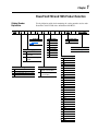
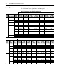
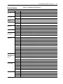
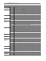
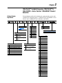
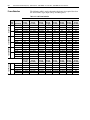
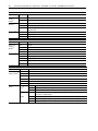
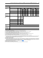
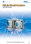
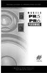
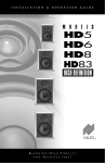
Bulletin 2362 Digital AC Drives in
CENTERLINE®
Motor Control
Centers
1336 PLUS™ - Variable Frequency
1336 PLUS™ II
1336 FORCE - Vector Control
1336 IMPACT
PowerFlex® 700
PowerFlex® 700S
Bulletin 2362 Units
Bulletin 2362HA
125HP Roll-Out Unit
Selection Guide
Table of Contents
Preface
Introduction
About This Publication . . . . . . . . . . . . . . . . . . . . . . . . . . . . . . . . . . . . . . . . . . . . . . . . . . .
General Product Description . . . . . . . . . . . . . . . . . . . . . . . . . . . . . . . . . . . . . . . . . . . . . . .
Plug-In Drive Units . . . . . . . . . . . . . . . . . . . . . . . . . . . . . . . . . . . . . . . . . . . . . . . . . . . .
Frame-Mounted Drive Units . . . . . . . . . . . . . . . . . . . . . . . . . . . . . . . . . . . . . . . . . . . . .
Roll-Out Drive Units . . . . . . . . . . . . . . . . . . . . . . . . . . . . . . . . . . . . . . . . . . . . . . . . . . .
UL Certification . . . . . . . . . . . . . . . . . . . . . . . . . . . . . . . . . . . . . . . . . . . . . . . . . . . . . . . .
Documentation . . . . . . . . . . . . . . . . . . . . . . . . . . . . . . . . . . . . . . . . . . . . . . . . . . . . . . . . .
Chapter 1
p-1
p-1
p-2
p-2
p-3
p-3
p-3
PowerFlex® 700 and 700S Product Selection
Catalog Number Explanation . . . . . . . . . . . . . . . . . . . . . . . . . . . . . . . . . . . . . . . . . . . . . . 1-1
Frame Selection. . . . . . . . . . . . . . . . . . . . . . . . . . . . . . . . . . . . . . . . . . . . . . . . . . . . . . . . . 1-2
Drive Unit Options . . . . . . . . . . . . . . . . . . . . . . . . . . . . . . . . . . . . . . . . . . . . . . . . . . . . . . 1-3
Chapter 2
1336 PLUS™ Variable Frequency, 1336 PLUS™ II, 1336 FORCE - Vector Control, 1336 IMPACT Product Selection
Catalog Number Explanation . . . . . . . . . . . . . . . . . . . . . . . . . . . . . . . . . . . . . . . . . . . . . . 2-1
Frame Selection. . . . . . . . . . . . . . . . . . . . . . . . . . . . . . . . . . . . . . . . . . . . . . . . . . . . . . . . . 2-2
Drive Unit Options . . . . . . . . . . . . . . . . . . . . . . . . . . . . . . . . . . . . . . . . . . . . . . . . . . . . . . 2-3
Chapter 3
Motor Control Center Vertical Sections
Features and Modifications . . . . . . . . . . . . . . . . . . . . . . . . . . . . . . . . . . . . . . . . . . . . . . . . 3-1
Chapter 4
Busbar Splice Kits
Understanding Busbar Splice Catalog Numbers. . . . . . . . . . . . . . . . . . . . . . . . . . . . . . . .
Determining Splice Kit Catalog Numbers . . . . . . . . . . . . . . . . . . . . . . . . . . . . . . . . . .
Splice Kit Catalog Numbers . . . . . . . . . . . . . . . . . . . . . . . . . . . . . . . . . . . . . . . . . . . . . . .
Power Bus Splice Kit Catalog Numbers . . . . . . . . . . . . . . . . . . . . . . . . . . . . . . . . . . . .
Control Bus Splice Kit Catalog Numbers . . . . . . . . . . . . . . . . . . . . . . . . . . . . . . . . . . .
PE/TE Bus Splice Kit Catalog Numbers. . . . . . . . . . . . . . . . . . . . . . . . . . . . . . . . . . . .
4-1
4-1
4-1
4-1
4-2
4-2
ii
Table of Contents
Preface
Introduction
About This Publication
Motor Control Centers offer a convenient design for the configuration of
AC drive lineups. When configured in conjunction with a Bulletin 2100
main incoming structure, the CENTERLINE® thru-bus solution eliminates
the challenge of low-voltage power distribution for drives.
We designed this publication to help you configure AC drive equipment
within Bulletin 2100 CENTERLINE Motor Control Center (MCC)
sections. The selection tables in this publication will help you specify the
necessary sections and units.
Important: When using this publication, please be sure to read all
footnotes. Footnotes are used throughout this publication to
advise you of configuration and limitation of structures, units,
and options.
For PowerFlex® drive units listed in Table 1.A:
• select drive unit options using Table 1.B
• select MCC vertical sections selected using Table 3.A
For 1336 drive units listed in Table 2.A:
• elect drive unit options using Table 2.B
• select MCC vertical sections selected using Table 3.A
If there is a need to purchase a separately-assembled unit (for example, if a
spare unit is desired), select the unit as listed in Table 1.A or Table 2.A.
When constructing the catalog number string, use the “N” enclosure
designation for NO structure assembly.
Options or equipment not offered through the 2362 standard AC drive unit
program can be provided to you as an engineered solution. Contact your
local Rockwell Automation Drive Systems representative.
General Product Description Bulletin 2362 AC motor drive units are specifically designed for use in
CENTERLINE® MCC lineups. You may select from numerous 1336
PLUS® Variable Frequency, 1336 PLUS® II Variable Frequency, 1336
FORCE Field-Oriented Control Vector, 1336 Impact, PowerFlex® 700, and
PowerFlex® 700S digital AC motor drives. You may have these drives
configured for either a common-AC or a common-DC power bus
configuration.
NEMA Class I, Type A-rated units are standard. To provide either a NEMA
Type 1 or a NEMA Type 1 with gaskets enclosure rating, the unit must be
installed into an appropriately-sized MCC vertical section. Terminals
p-2
Introduction
mounted within the drive units allow for the connection of remote operator
devices, I/O signals, etc.
Note: NEMA Type 1 is the standard feature; and NEMA Type 1 with unit
door area gaskets and door fan filters is available as an option.
A variety of available options provide increased unit functionality. The
following drive units are available:
Drive
1336
PowerFlex®
Frames
A, B, C
D, E, F, G
0, 1, 2, 3
4, 5, 6, 9
Unit Type
plug-in
roll-out
plug-in
frame-mounted
Plug-In Drive Units
The basic standard plug-in drive unit includes:
• the selected drive, mounted and wired in an MCC bucket
• a fused-disconnect switch with an operator mechanism and appropriate
fuses
• power and ground stabs for connecting to bus structure
• stab-to-disconnect wiring
• output common-mode chokes
• a unit support pan
• a vented door with fan(s), if appropriate
Note: MCC units that contain plug-in buckets come standard with
manual, vertical bus shutters.
Frame-Mounted Drive Units
The basic standard frame-mounted drive unit includes:
• the selected drive, mounted and wired on a panel-mounted assembly
• a fused-disconnect switch with an operator mechanism and appropriate
fuses
• bus-to-disconnect wiring
• output common-mode chokes
• a vented door with fan(s), if appropriate
Introduction
p-3
Roll-Out Drive Units
The basic standard roll-out drive unit includes:
• the selected drive, mounted and wired on a roll-out chassis assembly
• a fused-disconnect switch with an operator mechanism and appropriate
fuses
• bus-to-disconnect wiring
• output common-mode chokes in all D, E, and F-frame units and in
G-frame 2362H units (common DC bus 1336 FORCE)
• a vented door with fan(s), if appropriate
Note: All D and E-frame units and common DC bus F-frame units are
mounted in 20" deep vertical sections. Common AC bus F-frame
units and all G-frame units are mounted in 20" + 5" (bumpback)
deep vertical sections for ease of serviceability.
UL Certification
Bulletin 2100 CENTERLINE® Motor Control Centers are certified by
Underwriters Laboratories, Inc. (UL), Standard UL 845. The 2362 family of
AC drive units are UL/cUL listed. All vertical sections and units certified by
UL will carry the label. Vertical sections and units are labeled separately.
Documentation
The customer is supplied with copies of the following:
• the unit wiring diagram and installation instructions
• publications
– Bulletin 2300 Drive Systems Installation Manual (2300-5.1)
– the appropriate AC drive user manual
– Receiving, Handling, and Storing Motor Control Centers (2100-5.5)
For additional documentation, consult your Rockwell Automation Sales
Office.
p-4
Notes:
Introduction
Chapter
1
PowerFlex® 700 and 700S Product Selection
Catalog Number
Explanation
2362
S
Use the following tables for determining the catalog number used to order
PowerFlex 700 and 700S drives in Bulletin 2362 MCCs.
A
-
4
Frame Size
See Table 1.A on
page 1-2
A
B
T
Q
R
S
T
Wiring Type
“A” Type
“A” Type Power Wiring with
Bottom Exit
“A” Type Power Wiring with
Top Exit
Drive Type
PowerFlex® 700 (AC Common Bus)
PowerFlex® 700 (DC Common Bus)
PowerFlex® 700S (AC Common Bus)
PowerFlex® 700S (DC Common Bus)
A
J
A
B
A
J
B
C
D
V
E
F
-
Input Voltages
230V AC Bus
380V AC Bus
460V AC Bus
575V AC Bus
310V DC Bus
512V DC Bus
620V DC Bus
775V DC Bus
Enclosure
NEMA Type 1 with no
gaskets or door fan filters
NEMA Type 1 with gaskets
or door fan filters
48
DA
-
OPTIONS
Disconnect Type
DA Fused Disconnect
Options
See Table 1.B on page 1-3
Horsepower Rating(3)
85 0.33
33 0.5
34 0.75
35 1.0
36 1.5
37 2.0
38 3.0
39 5.0
40 7.5
41 10
42 15
43 20
44 25
45 30
46 40
47 50
48 60
49 75
50 100
51 125
52 150
54 200
56 250
57 300
58 350
59 400
60 450
61 500
62 600
63 650
64 700
66 800
1-2
PowerFlex® 700 and 700S Product Selection
Frame Selection
The following table is used to determine the frame size required based on
the desired Drive Type, Input Voltage and Horsepower.
Table 1.A PowerFlex 700 ad 700S Frame Selection
Drive
Type
Duty
Code Input Voltage Rating
Q
230V AC
ND - HP
HD - HP
380V AC
ND - kW
HD - kW
460V AC
ND - HP
HD - HP
575V AC
ND - HP
HD - HP
R
310V DC
ND - HP
HD - HP
512V DC
ND - kW
HD - kW
620V DC
ND - HP
HD - HP
775V DC
ND - HP
HD - HP
Drive
Type
Code
S
Input
Voltage
230V AC
380V AC
460V AC
575V AC
T
310V DC
512V DC
620V DC
775V DC
(1)
Duty
Rating
ND - HP
HD - HP
ND - kW
HD - kW
ND - HP
HD - HP
ND - HP
HD - HP
ND - HP
HD - HP
ND - HP
HD - HP
ND - HP
HD - HP
ND - HP
HD - HP
0
(2.0 SF
20” Wide)
0.5 - 1
0.33 - 0.75
0.75 - 4
0.55 - 3
0.5 - 7.5
0.33 - 5
0.5 - 10
0.75 - 7.5
0.5 - 1
0.33 - 0.75
0.75 - 4
0.55 - 3
0.5 - 7.5
0.33 - 5
0.5 - 10
0.75 - 7.5
1
(2.0 SF
20” Wide)
0.5 - 7.5
0.33 - 5
0.75 - 11
0.55 - 7.5
0.5 - 15
0.33 - 10
0.5 - 15
0.33 - 10
0.5 - 7.5
0.33 - 5
0.75 - 11
0.55 - 7.5
0.5 - 15
0.33 - 10
0.5 - 15
0.33 - 10
Frame 10 is a 25 inch deep, flush-back enclosure.
1
(2.0 SF
20” Wide)
2 - 7.5
1.5 - 5
7.5 - 11
5.5 - 7.5
10 - 15
7.5 - 10
10 - 15
7.5 - 10
2 - 7.5
1.5 - 5
7.5 - 11
5.5 - 7.5
10 - 15
7.5 - 10
10 - 15
7.5 - 10
2
(2.0 SF
20” Wide)
10
7.5
15 - 18.5
11 - 15
20 - 25
15 - 20
20 - 25
15 - 20
10
7.5
15 - 18.5
11 - 15
20 - 25
15 - 20
20 - 25
15 - 20
PowerFlex® 700 Frame Sizes
2
3
4
(2.0 SF
(3.0 SF
(6.0 SF
20” Wide)
20” Wide)
20” Wide)
10
15 - 20
25 - 30
7.5
10 - 15
20 - 25
15 - 18.5
22 - 37
45
11 - 15
18.5 - 30
37
20 - 25
30 - 50
60
15 - 20
25 - 40
50
20 - 25
30 - 50
60
15 - 20
25 - 40
50
10
15 - 20
25 - 30
7.5
10 - 15
20 - 25
15 - 18.5
22 - 37
45
11 - 15
18.5 - 30
37
20 - 25
30 - 50
60
15 - 20
25 - 40
50
20 - 25
30 - 50
60
15 - 20
25 - 40
50
5
(6.0 SF
20” Wide)
40 - 50
30 - 40
55 - 75
45 - 55
75 - 100
60 - 75
75 - 100
60 - 75
40 - 50
30 - 40
55 - 75
45 - 55
75 - 100
60 - 75
75 - 100
60 - 75
PowerFlex® 700S Frame Sizes
3
4
5
6
(3.0 SF
(6.0 SF
(6.0 SF
(6.0 SF
20” Wide) 20” Wide) 20” Wide) 25” Wide)
15 - 20
25 - 30
40 - 50
60 - 75
10 - 15
20 - 25
30 - 40
50 - 60
22 - 37
45
55 - 75
90 - 132
8.5 - 30
37
45 - 55
75 - 110
30 - 50
60
75 - 100
125 - 150
25 - 40
50
60 - 75
75 - 125
30 - 50
60
75 - 100
125 - 150
25 - 40
50
60 - 75
100 - 125
15 - 20
25 - 30
40 - 50
60 - 75
10 - 15
20 - 25
30 - 40
50 - 60
22 - 37
45
55 - 75
90 - 132
8.5 - 30
37
45 - 55
75 - 110
30 - 50
60
75 - 100
125 - 150
25 - 40
50
60 - 75
100 - 125
30 - 50
60
75 - 100
125 - 150
25 - 40
50
60 - 75
100 - 125
9
(6.0 SF
30” Wide)
NA
NA
132 - 160
110 - 132
200 - 250
150 - 200
150 - 200
150
NA
NA
132 - 160
110 - 132
200 - 250
150 - 200
150 - 200
150
6
(6.0 SF
25” Wide)
60 - 75
50 - 60
90 - 132
75 - 110
125 - 150
100 - 125
125 - 150
100 - 125
60 75
50 - 60
90 - 132
75 - 110
125 - 150
100 - 125
125 - 150
100 - 125
10
(6.0 SF
35” Wide)(1)
NA
NA
(Future)
(Future)
(Future)
(Future)
(Future)
(Future)
NA
NA
(Future)
(Future)
(Future)
(Future)
(Future)
(Future)
PowerFlex® 700 and 700S Product Selection
Drive Unit Options
Options Available to All Units:
Option
Option Code
Control Power
Source(1)(6)
6P
Table 1.B PowerFlex® 700 and 700S Drives
Description
Individual 115V AC-secondary, control power transformer (supplied per drive unit). Includes primary fusing
6TB
115V AC control power, factory wired from 115V AC control bus to drive unit (requires control bus)
6SC
115V AC control power supplied by customer
Auxiliary Contact for 98
Disconnect(3)
99
1-3
(1) normally open (Y = option avail.)
(1) normally closed (Y = option avail.)
Wire Label Upgrade 14WLBL
Option(10)
Brady Datab™ wire labels
T-Handles(2)
111
T-handles on doors and 3” vertical wireway (present in MCC sections containing frame 0, 1, 2, & 3 drive units
110
Standard handles
Door-Mounted
Devices(4)
Miscellaneous
Unit Door
Nameplates(1)
Communication
Adapters(1)(15)
1ES
Hardwired-interface-stop-pushbutton; for drive-disable function
4EA
Control-power-on pilot light
4EW
Drive-faulted pilot light
J11
Audio phone jack
J12
115V AC, 15A, duplex receptacle
M3EW
Phenolic label with white background and black lettering
N3EB
Phenolic label with black background and white lettering
N3ER
Phenolic label with red background and white lettering
14PNA
No Communication adapter
14PCNC
DPI - ControlNet adapter, coaxial cable
14PCNF
DPI - ControlNet adapter, fiber optic
14PDF1
DPI - RS485 DF-1 adpater
14PDPV1
DPI - PROFIBUS DPV-1 adapter
14PEA
DPI - Ethernet adapter
14PG1
DPI - Single-Point Remote I/O (RIO) adapter
14PG5
DPI - DeviceNet adapter
14PHVA
DPI - RS485 HVAC adapter (future)
14PIB
DPI - Interbus adapter (future)
14PLW
DPI - LonWorks® adapter (future)
14DLD
Communication
Adpater (PowerFlex 14DLE
700S with DriveLogix
14DLOC
Only)(1)(15)
14DLOF
14DLORC
Human Interface
Module (HIM)(3)
Drive Enclosure(1)
ELC - DeviceNet adapter
ELC - EtherNet adapter
ELC - ControlNet adapter, coaxial cable
ELC - ControlNet adapter, fiber optic
ELC - ControlNet Redundant adapter, coaxial cable
14DLORF
ELC - ControlNet Redundant adapter, fiber optic
14HAPC
Door-mounted HIM, Programmer Only LCD
14HA3C
Door-Mounted HIM with full numeric LCD
HA1C
Drive-Mounted Him with analog LCD
HA2C
Drive-Mounted HIM with digital LCD
HA3C
Drive-Mounted HIM with full numeric LCD
HAP
Door-Mounted HIM Programmer Only LCD
14DO
Open
14D1
NEMA 1
14D12
NEMA 12
14DF
Flange
1-4
PowerFlex® 700 and 700S Product Selection
Options Available to All Units:
Option
Option Code
Description
Drive Duty Cycle(1)
99ND
Normal Duty
99HD
Heavy Duty
14EMA
CE filter and common mode choke(18)(19)(21)
14EMB
CE filter and no common mode choke(20)(21)
14EMB1
CE filter and external common mode choke(22)
14EMN
No CE filter and no common mode choke(22)(23)
14EMN1
No CE filter and external common mode choke(22)(23)
Emissions(1)
Documentation(1)(16) N
No documentation
A
English User Manual
E
Quick Start Guide and CD
I/O Selection
(PowerFlex 700
Only)(1)
14IOC
Vector I/O, 24V
14IOD
Vector I/O, 115V
Control (PowerFlex
700S Only)(1)
14CIOA
Phase II with expanded cassette, no Logix extras, no SynchLink™
14CIOB
Phase II with expanded cassette, no Logix extras, with SynchLink
14CIOC
Phase II with expanded cassette, with Logix extras, no SynchLink(14)
14CIOD
Phase II with expanded cassette, with Logix extras, with SynchLink(14)
14CIOG
Phase II slim cassette, no Logix extras, no SynchLink
14CIOH
Phase II slim cassette, no Logix extras, with SynchLink
ELC2SNN
Phase II, no DriveLogix, no embedded comm.
ELC2SNE
Phase II, no DriveLogix, EtherNet/IP embedded comm.
Configurations(1)
ELC2SNC
Phase II, no DriveLogix, ControlNet embedded comm.
ELC2SEN
Phase II, 5730 DriveLogix™, no embedded comm.
ELC2SEE
Phase II, 5730 DriveLogix, EtherNet/IP embedded comm.
ELC2SEC
Phase II, 5730 DriveLogix, ControlNet embedded comm.
Compact I/O
Cable(17)
CIOL
Drive to left bank expansion
CIOR
Drive to right bank expansion
Feedback
(PowerFlex 700
Only)(1)
14ENC
Standard encoder
14ENCN
No feedback PCB
Feedback
(PowerFlex 700S
Only)(1)
14EN2
Second encoder feedback(14)
14HEF
Heidenhain feedback PCB(13)
14HENC
Hi-Resolution Stegmann resolver feedback PCB(13)
14MDI
Multi-Device Interface(13)
14PN
No feedback PCB
14RES
Resolver feedback PCB(13)
14SO
Safe-Off (includes second encoder feedback)(14)
16BI
Braking IGBT included
Braking Option(1)
Braking Resistor(1)
16BNI
Braking IGBT not included
14BR
Braking resistor included
14BRN
Braking resistor not included
14BRE
Braking resistor, external
XBC
1.5 inch high base channels
XBSM
Bottom support angle multi-section
Enclosure Options
MCC Bottom
Support(1)(5)
PowerFlex® 700 and 700S Product Selection
Options Available to All Units:
Option
Option Code
Horizontal Power
Bus(3)(7)(9)(11)(12)
Description
08-AC
800A AC power bus
08-DC
800A DC power bus
12-AC
1200A AC power bus
16-AC
1600A AC power bus
16-DC
1600A DC power bus
20-AC
2000A AC power bus
30-AC
3000A AC power bus
30-DC
3000A DC power bus
Ground Bus (PE/
TE)(1)(8)
XTEP2
PE/TE bus for unit with horizontal bus rated up to 2000A
XTEP3
PE/TE bus for unit with horizontal bus rated up to 3000A
115V AC Control
Bus(9)
X115
90A control bus
Top Hat
(1)
(2)
(3)
(4)
(5)
(6)
(7)
(8)
(9)
(10)
(11)
(12)
(13)
(14)
(15)
(16)
(17)
(18)
(19)
(20)
(21)
(22)
(23)
12 inch high top hat for extra entry cable bending radius
You must select (1) option from this group.
All drives mounted in the same MCC vertical section must have option 111 if any one drive unit has option 111.
You may select up to (1) option from this group.
Pilot lights are Allen-Bradley® Bulletin 800M products and the pushbutton is an Allen-Bradley Bulletin 800T device.
If one drive unit has base channels in any lineup, the entire lineup must have base channels. Base channels add 1.5 inches to the unit height.
Option 6P is not available for drive units with voltage codes D, S, E, and F.
Units with voltage codes D, S, E and F require horizontal power bus options. Only 800A, 1600A, and 3000A are available.
You must select a ground bus option. If your lineup has a 3000A power bus, you must select the ground bus option for units with a 3000A-rated power bus.
You must select a horizontal power bus option if you select a control bus.
Units come standard with cloth wire labels. Datab labels offer the added protection of a clear plastic cover on top of the labels.
Horizontal power bus is braced for 65kAIC.
Maximum of 120 inches per shipping split.
Requires an expended cassette for Phase II control.
Available for Phase II control only. Requires an expanded cassette.
For dual communications (DPI and DriveLogix) select the DriveLogix comm. option and order the DPI comm. kit separately.
PowerFlex 700 frame 0 - 6 allows the “N” or “A” selections only. PowerFlex 700 frame 9 allows the “A” selection only. PowerFlex 700S frames 1 - 9 allows the “N” or “E” selections only.
PowerFlex 700S only, requires an expanded cassette with Logix extras PCB.
Required for PowerFlex 700S frames 1 - 6.
Required for PowerFlex 700 frames 0 - 6 with voltages 380V AC, 460V AC, 575V AC, 512V DC, 620V DC, and 775V DC
Required for PowerFlex 700 frames 0 - 2 with voltages 230V AC and 310 V DC
You must select one (1) of these options for PowerFlex 700 frame 3 with voltages 230V AC and 310 V DC
You must select one (1) of these options for PowerFlex 700S frame 9 with voltages 380V AC, 460V AC and 575V AC
You must select one (1) of these options for PowerFlex 700S frame 9 with voltages 512V DC, 620V DC and 775V DC
1-5
1-6
Notes:
PowerFlex® 700 and 700S Product Selection
Chapter
2
1336 PLUS™ Variable Frequency, 1336 PLUS™ II,
1336 FORCE - Vector Control, 1336 IMPACT Product
Selection
Catalog Number
Explanation
2362
S
Use the following tables for determining the catalog number used to order
1336 PLUS™ Variable Frequency, 1336 PLUS™ II, 1336 FORCE - Vector
Control, and 1336 IMPACT drives in Bulletin 2362 MCCs.
A
-
4
Frame Size
See Table 2.B on
page 2-3
A
B
T
E
F
G
H
L
M
N
P
Wiring Type
“A” Type
“A” Type Power Wiring with
Bottom Exit
“A” Type Power Wiring with
Top Exit
Drive Type
1336S PLUS (AC Common Bus)
1336T FORCE (AC Common Bus)
1336S PLUS (DC Common Bus)
1336T FORCE (DC Common Bus)
1336E IMPACT (AC Common Bus)
1336E IMPACT (DC Common Bus)
1336E PLUS II (AC Common Bus)
1336E PLUS II (DC Common Bus)
A
J
A
B
A
N
B
C
D
S
E
F
-
Input Voltages
230V AC Bus
380V AC Bus
460V AC Bus
575V AC Bus
310V DC Bus
512V DC Bus
620V DC Bus
775V DC Bus
Enclosure
NEMA Type 1 with no
gaskets or door fan filters
NEMA Type 1 with gaskets
or door fan filters
48
DA
-
OPTIONS
Disconnect Type
DA Fused Disconnect
Options
See Drive Unit Options on page 2-3
Horsepower Rating(3)
33 0.5
34 0.75
35 1.0
36 1.5
37 2.0
38 3.0
39 5.0
40 7.5
41 10
42 15
43 20
44 25
45 30
46 40
47 50
48 60
49 75
50 100
51 125
52 150
54 200
56 250
57 300
58 350
59 400
60 450
61 500
62 600
63 650
64 700
66 800
2-2
1336 PLUS™ Variable Frequency, 1336 PLUS™ II, 1336 FORCE - Vector Control, 1336 IMPACT Product Selection
Frame Selection
The following table is used to determine the frame size required based on
the desired Drive Type, Input Voltage and Horsepower.
1336E IMPACT
1336T FORCE
1336S PLUS
Table 2.A 1336 Frame Selection
Drive
Type
Code Input Voltage
E
230V AC
380/460V AC
575V AC
G
310V DC
512/620V DC
775V DC
F
230V AC
380/460V AC
575V AC
H
310V DC
512/620V DC
775V DC
L
230V AC
380/460V AC
575V AC
M
310V DC
512/620V DC
775V DC
A
(1.5 SF
20” Wide)
0.5 - 5.0 HP
0.5 - 5.0 HP
1, 3 HP
0.5 - 5.0 HP
0.5 - 5.0 HP
1, 3 HP
NA
NA
NA
NA
NA
NA
0.5 - 5.0 HP
0.5 - 5.0 HP
1, 3 HP
0.5 - 5.0 HP
0.5 - 5.0 HP
1, 3 HP
A
(1.5 SF <= 5 HP
2.5 SF >5 HP
1336F PLUS II
N
(1)
P
230V AC
380/460V AC
575V AC
310V DC
512/620V DC
775V DC
NA = Not Available
20” Wide)
0.5 - 5.0 HP
0.5 - 15 HP
0.5 - 20 HP
0.5 - 5.0 HP
0.5 - 15 HP
0.5 - 20 HP
B
(2.5 SF
20” Wide)
7.5 - 15 HP
7.5 - 30 HP
7.5 - 20 HP
7.5 - 15 HP
7.5 - 30 HP
7.5 - 20 HP
1, 3, 7.5 - 15 HP
1, 3, 7.5 - 30 HP
1, 3, 7.5 - 20 HP
1, 3, 7.5 - 15 HP
1, 3, 7.5 - 30 HP
1, 3, 7.5 - 20 HP
7.5 - 15 HP
7.5 - 30 HP
7.5 - 20 HP
7.5 - 15 HP
7.5 - 30 HP
7.5 - 20 HP
C
(3.5 SF
20” Wide)
10 - 30 HP
40 - 50 HP
25 - 60 HP
10 - 30 HP
40 - 50 HP
25 - 60 HP
20 - 30 HP
40 - 50 HP
25 - 60 HP
20 - 30 HP
40 - 50 HP
25 - 60 HP
10 - 30 HP
40 - 50 HP
25 - 60 HP
10 - 30 HP
40 - 50 HP
25 - 60 HP
1336 Frame Sizes
D
E
(6.0 SF
(6.0 SF
20” Wide) 25” Wide)
NA(1)
NA
60 - 125 HP 150 - 250 HP
75 - 125 HP 150 - 300 HP
NA
NA
60 - 125 HP 150 - 250 HP
75 - 125 HP 150 - 300 HP
NA
NA
60 - 125 HP 150 - 250 HP
75 - 125 HP 150 - 300 HP
NA
NA
60 - 125 HP 150 - 250 HP
75 - 125 HP 150 - 300 HP
NA
NA
60 - 125 HP 150 - 250 HP
75 - 125 HP 150 - 300 HP
NA
NA
60 - 125 HP 150 - 250 HP
75 - 125 HP 150 - 300 HP
F
(6.0 SF
35” Wide)
NA
300 - 400 HP
350 - 400 HP
NA
300 - 400 HP
350 - 400 HP
NA
300 - 400 HP
350 - 400 HP
NA
300 - 400 HP
350 - 400 HP
NA
300 - 400 HP
350 - 400 HP
NA
300 - 400 HP
350 - 400 HP
G
(6.0 SF
35” Wide)
NA
450 - 600 HP
450 - 650 HP
NA
450 - 600 HP
450 - 650 HP
NA
450 - 600 HP
450 - 650 HP
NA
450 - 600 HP
450 - 650 HP
NA
450 - 600 HP
450 - 650 HP
NA
450 - 600 HP
450 - 650 HP
B
(2.5 SF
20” Wide)
7.5 - 15 HP
20 - 30 HP
7.5 - 20 HP
7.5 - 15 HP
20 - 30 HP
7.5 - 20 HP
C
(3.5 SF
20” Wide)
20 - 30 HP
40 - 50 HP
25 - 60 HP
20 - 30 HP
40 - 50 HP
25 - 60 HP
D
(6.0 SF
20” Wide)
NA
60 - 125 HP
75 - 125 HP
NA
60 - 125 HP
75 - 125 HP
F
(6.0 SF
35” Wide)
NA
300 - 400 HP
350 - 400 HP
NA
300 - 400 HP
350 - 400 HP
G
H
(6.0 SF
(6.0 SF
35” Wide) 35” Wide)
NA
NA
450 - 600 HP
NA
450 - 650 HP
NA
NA
NA
450 - 600 HP
NA
450 - 650 HP
NA
E
(6.0 SF
25” Wide)
NA
150 - 250 HP
150 - 300 HP
NA
150 - 250 HP
150 - 300 HP
H
(6.0 SF
35” Wide)
NA
NA
NA
NA
NA
NA
NA
NA
NA
NA
700, 800 HP
700, 800 HP
NA
NA
NA
NA
700, 800 HP
700, 800 HP
1336 PLUS™ Variable Frequency, 1336 PLUS™ II, 1336 FORCE - Vector Control, 1336 IMPACT Product Selection
Drive Unit Options
2-3
Table 2.B Drive Unit Options
Options Available to All Units:
Option
Option Code
Description
Control Power
Source(1)(6)
6P
Individual 115V AC-secondary, control power transformer (supplied per drive unit). Includes primary fusing
6TB
115V AC control power, factory wired from 115V AC control bus to drive unit (requires control bus)
6SC
115V AC control power supplied by customer
Auxiliary Contact
98
for
Disconnect(3)(5) 99
230V AC / 380V AC / 512V DC / 575V AC 775V DC
Input Voltage > 310V DC 460V AC 620V DC
Frame Size > A,B,C A,B,C,D,E F,G,H A,B,C,D,E F,G,H
(1) normally open (Y = option avail.)
Y
Y
Y
(1) normally closed (Y = option avail.)
Y
Y
Y
989
(1) normally open + (1) normally closed (Y = option
avail.)
Wire Label
Upgrade
Option(11)
14WLBL
Brady Datab™ wire labels
T-Handles(2)
111
T-handles on doors and 3” vertical wireway (present in MCC sections containing frame A, B, & C drive units
Door-Mounted
Devices(4)
1ES
Hardwired-interface-stop-pushbutton; for drive-disable function
4EA
Control-power-on pilot light
4EB
Drive-at-speed pilot light
4ER
Drive-run pilot light
Miscellaneous
Unit Door
Nameplates(1)
Communication
Adapters(3)
Human Interface
Module (HIM)(3)
4EW
Drive-faulted pilot light
J11
Audio phone jack
J12
115V AC, 15A, duplex receptacle
M3EW
Phenolic label with white background and black lettering
N3EB
Phenolic label with black background and white lettering
N3ER
Phenolic label with red background and white lettering
14CN1
DPI - SCANport™ to ControlNet adapter
14G1
SCANport to Single-Point Remote I/O (RIO) adapter
14G2
SCANport to RS232/422/485, DF1, or DH485 adapter
14G5
SCANport to DeviceNet adapter
14HA1C
Door-mounted HIM with analog potentiometer
14HA2C
Door-mounted HIM with digital potentiometer
14HAPC
Door-mounted HIM, Programmer Only LCD
14HNBC
Door-mounted connector permitting connection of a hand-held HIM or GPT through closed-door unit
Options Available to 2362E & 2362G Units:
Option
Option Code
Control Logic
Interface
Boards(3)
14L5
24V DC
14L5E
24V DC with encoder feedback
Languages(1)
Y
Description
14L6
115V AC
14L6E
115V AC with encoder feedback
14DE
English/German
14EN
English/English
14ES
English/Spanish
14FR
English/French
14IT
English/Italian
Y
2-4
1336 PLUS™ Variable Frequency, 1336 PLUS™ II, 1336 FORCE - Vector Control, 1336 IMPACT Product Selection
Options Available to 2362F & 2362H Units:
Option
Option Code
Control Logic
Interface
Boards(3)
14L5
24V DC
14L6
115V AC
Drive Adapter
Boards(1)
14CN
ControlNet (version 1.5) Adapter
Languages(1)
Description
14PCA
PLC Comm Adapter
14SA
Standard Adapter (If you selected Control Logic Interface Board 14L5 or 14L6, you must choose this Drive
Adapter Board.)
14EN
English/English
14ES
English/Spanish
14FR
English/French
Options Available to 2362L & 2362M Units:
Option
Option Code
Control Logic
Interface
Boards(3)
14L5
24V DC
14L6
115V AC
Languages(1)
Description
14L8E
24V DC with encoder feedback and encoder loss detection
14L9E
115V AC with encoder feedback and encoder loss detection
14DE
English/German
14EN
English/English
14ES
English/Spanish
14FR
English/French
14IT
English/Italian
Options Available to 2362N & 2362P Units:
Option
Option Code
Control Logic
14L5
Interface Boards(3) 14L5E
Analog Interface
Board
Description
24V DC
24V DC with encoder feedback
14L6
115V AC
14L6E
115V AC with encoder feedback
14L8E
24V DC with encoder feedback and encoder loss detection
14L9E
115V AC with encoder feedback and encoder loss detection
Port A(3)
Port B(3)
14LA2 =
(2) isolated, configurable inputs
14LA6 =
(3) non-isolated, thermistor/RTD inputs
14LA7 =
(1) isolated, bipolar input (+/- 10V and (1) isolated, configurable input
14LA1 =
(1) single-ended, non-isolated, configurable input OR (1) potentiometer & (2) single-ended,
non-isolated, 1-to-20mA outputs
14LA3 =
(2) isolated, configurable outputs
14LA4 =
(1) isolated, configurable input and output
14LA5 =
(1) isolated, pulse input and output & (1) single-ended, non-isolated, 0-to-10V output
1336 PLUS™ Variable Frequency, 1336 PLUS™ II, 1336 FORCE - Vector Control, 1336 IMPACT Product Selection
2-5
Enclosure Options Available to All Units:
Description
Y
1.5 Inch High
Base
Channels(5)(7)
Required (R) or Optional (O):
Horizontal Power
Bus(8)(13)(14)(15)
O
Input Voltage > 230V AC
380V AC
460V AC
575V AC
(16)
Y
Y
Y
800A (Y = option avail.)
Y
1200A (Y = option avail.)
Y
1600A (Y = option avail.)
Y
2000A (Y = option avail.)
Y
3000A (Y = option avail.)
Y
O
O
R
Y
Y
Y
O
O
R
Y
Y
Y
O
O
G, H
Y
D, E, F
Y
775V DC
A, B, C
Y
G, H
Y
D, E, F
Y
25” deep MCC (Y = option avail.)
512V/620V DC
A, B, C
Y
Y
310V DC
A, B, C
20” deep MCC (Y = option avail.)
F, G
Y
D, E
Y
575V AC
A, B, C
15” deep MCC (Y = option avail.)
Frame Size >
F, G
380/460V AC
A, B, C
Input Voltage > 230V AC
A, B, C
Section
Depth(7)(12)
D, E
Option
O
R
Y
O
O
R
310V DC
512V DC
620V DC
775V DC
Y
Y
Y
Ground Bus (PE/ PE/TE bus for unit with horizontal power bus rated up to 2000A
TE)(9)(16)
PE/TE bus for unit with horizontal power bus rated up to 3000A
115V AC Control 90A control bus
Bus(10)(16)
Top Hat(17)
(1)
(2)
(3)
(4)
(5)
(6)
(7)
(8)
(9)
(10)
(11)
(12)
(13)
(14)
(15)
(16)
(17)
(18)
(19)
(20)
12” high top hat for extra entry cable bending radius
You must select (1) option from this group.
All drives mounted in the same MCC vertical section must have option 111 if any one drive unit has option 111.
You may select up to (1) option from this group.
Pilot lights are Allen-Bradley® Bulletin 800M products and the pushbutton is an Allen-Bradley Bulletin 800T device.
If one drive unit has base channels in any lineup, the entire lineup must have base channels. Base channels add 1.5 inches to the unit height.
Option 6P is not available for drive units with voltage codes D, S, E, and F.
If you are connecting to an FD86N cabinet, you must select base channels and enclosures that are 20 inches and/or 25 inches deep.
Units with voltage codes D, S, E and F require horizontal power bus options. Only 800A, 1600A, and 3000A are available.
You must select a ground bus option. If your lineup has a 3000A power bus, you must select the ground bus option for units with a 3000A-rated power bus.
You must select a horizontal power bus option if you select a control bus.
Units come standard with cloth wire labels. Datab labels offer the added protection of a clear plastic cover on top of the labels.
If at least one unit in a lineup is 20 inches or 25 inch deep flush back, then all other drive units in that lineup must be 20 inches or 25 inches deep.
If the drive unit is mounted in a 25 inch deep flush front enclosure, you must select a 3000A horizontal power bus for that unit. If you have drives mounted in 15 inch or 20 inch deep sections
in the same lineup, you may select a different horizontal power bus option; but all non-25 inch deep enclosure units in a lineup must have the same horizontal power bus option. The
horizontal power bus rating of the entire lineup equals the lowest power bus rating selected.
Horizontal power bus is braced for 65kAIC.
Maximum of 120 inches per shipping split.
Horizontal power bus and control bus (if selected) are mounted at a depth of 11.94 inches in all MCC sections containing frame A, B, and C drive units, regardless of section depth. Frame
D, E, F, G, and H drives units have power bus and control bus (if selected) mounted at a depth of 16.94 inches or greater with bus ends for splicing always at a depth of 16.94 inches. Select
offset splice kit(s) when shipping split requires splicing bus ends at a depth of 11.94 inches to bus ends at a depth of 16.94 inches. If both sections have bus ends at the same depth, select
straight splice kits. Use the tables in the Power Bus Splice Kit Catalog Numbers section on page 4-1 to select splice splits per shipping split.
Frame F, G, and H drive units require top hats if input power is not supplied by a power bus option.
Requires an expended cassette for Phase II control.
Available for Phase II control only. Requires an expanded cassette.
For dual communications (DPI and DriveLogix) select the DriveLogix comm. option and order the DPI comm. kit separately.
2-6
Notes:
1336 PLUS™ Variable Frequency, 1336 PLUS™ II, 1336 FORCE - Vector Control, 1336 IMPACT Product Selection
Chapter
3
Motor Control Center Vertical Sections
Features and Modifications
Section Features and
Modifications
Section
Depth
Horizontal
Power Bus
Table 3.A Motor Control Center Vertical Section Features and Modifications
App. Notes
1, 2, 3, 10
4
Description
15” Deep
20” Deep
25” Deep (flush back)
Tin-plated copper busbar
4, 5
Horizontal Power
Bus Bracing
Horizontal
Power Bus
Splice Kit
Horizontal (PE / TE)
Ground Bus
Horizontal Ground
Bus Splice Kit
Horizontal Control Bus
Horizontal Control Bus
Splice Kit
Pull Box
Blank Unit Doors
Base Channels
6
Bus
Rating
800A
1200A (AC only)
1600A
2000A
3000A
42kAIC (rms Symmetrical)
65kAIC (rms Symmetrical)
Splice bars and assembly
hardware.
6
Bus
Rating
800A
1200A
1600A
2000A
3000A
1/4” x 1” PE and 1/4” x 1” TE tin-plated copper bus
1/4” x 2” PE and 1/4” x 1” TE tin-plated copper bus
For 1/4” x 1” PE and 1/4” x 1” TE tin-plated copper bus
For 1/4” x 2” PE and 1/4” x 1” TE tin-plated copper bus
Tin-plated copper 115V AC control bus rated at 90A
For tin-plated copper 115V AC control bus rated at 90A
7, 8, 9
12” High x 15” Deep, 20” Deep OR 25” Deep
Covers unused unit space (includes 0.5 SF
unit support pan)
1.0 SF
1.5 SF
2.0 SF
2.5 SF
3.5 SF
4.5 SF
Two 1.5” x 3” mounting channels (One front, one rear)
5, 6
4, 5
5, 6
1 All 1336 D and E-frame drive units and common DC bus F-frame drive units and PowerFlex frames 4 - 9 have 20" deep sections as standard. Common AC bus F-frame drive units and all
G-frame and H-frame drive units have 25"bump-back sections as standard.
2 If you are using a Bulletin 2364 front-end common-DC-bus supply unit in your lineup, verify that the front-end depth is compatible with the Bulletin 2362 sections that you are selecting.
3 If ANY one section is at least 20" deep, then ALL sections in that lineup must be at least 20" deep.
4 You must specify a power bus and a ground bus for each section.
5 3000A-rated horizontal power bus requires a 1/4" x 2" horizontal ground bus (PE) selection. Zero potential bus (TE) remains at 1/4" x 1" regardless of horizontal ground bus (PE) size selection.
Splice kits with 1/4" x 2" PE contain three 1/4" x 1" bus splices (Qty 2 for PE + Qty 1 for TE); splice kits with 1/4" x 1" PE contain two.
6 One kit required per shipping split on flush-front lineups. (Control bus splice kits are only required if lineup has control bus.)
7 Common AC bus F-frame drive units and all G-frame and H-frame drive units require base channels.
8 If you are using a Bulletin 2364 front-end unit in your lineup, lookup the base channel requirements of the front-end being utilized.
9 If ANY one section has base channels, then ALL sections in that lineup must have this optional base channel factory-installed. Base channels add 1.5" to the overall section height.
10 PowerFlex® frame 10 requires a 25” deep flush back section.
3-2
Notes:
Motor Control Center Vertical Sections
Chapter
4
Busbar Splice Kits
Understanding Busbar
Splice Catalog Numbers
Each character of the catalog number identifies a specific type or size of a
particular busbar splice kit. The first four numbers represent the family of
products (for example, 2300). The remaining characters represent a specific
version.
Determining Splice Kit Catalog Numbers
To help you to understand, we will provide an example of how to determine
a catalog number for a Bulletin 2300 Family busbar splice kit.
The beginning portion of the catalog number for all 2300 busbar splice kits
is 2300H (H is for a hardware kit). The remaining portion of the catalog
number will represent the particular type of kit.
The catalog number is organized as follows:
2300
H
-
SK
Busbar type
-
Busbar splice shape
Power Bus Current Rating
For example, a catalog number on the following page for 2300H-SKA-Z16
would mean:
• a common-AC power bus system
• a power bus rating of 1600 Amps
• an offset splice is needed
Splice Kit Catalog Numbers
Power Bus Splice Kit Catalog Numbers
For:
Splicing directly to a common AC bus F-frame
2362 unit or any G-frame 2362 unit
All other AC common bus splicing applications
All DC common bus splicing applications
Use:
Table 4.C
Table 4.A
Table 4.B
Table 4.A AC Power Bus Splice Kits
Compatible with Frame Sizes
1336
PowerFlex
A, B, C, D, E 0 - 9
A, B, C, D, E 0 - 9
A, B, C, D, E 0 - 9
A, B, C, D, E 0 - 9
A, B, C, D, E 0 - 9
A, B, C, D, E 0 - 9
F, G, H
Continuous Power Bus
Rating (Amps)
800
1200
1600
2000
2500
3000
Up to 3000
Straight Splice Kit
2300H-SKA-L08
2300H-SKA-L12
2300H-SKA-L16
2300H-SKA-L20
2300H-SKA-L25
2300H-SKA-L30
2300H-SKA-L30S
Offset Splice Kit
2300H-SKA-Z08
2300H-SKA-Z12
2300H-SKA-Z16
2300H-SKA-Z20
2300H-SKA-Z25
2300H-SKA-Z30
2300H-SKA-Z30
4-2
Busbar Splice Kits
Table 4.B DC Power Bus Splice Kits
Compatible with Frame Sizes
1336
PowerFlex
A, B, C, D, E, F 0 - 9
A, B, C, D, E, F 0 - 9
A, B, C, D, E, F 0 - 9
G, H
Continuous Power Bus
Rating (Amps)
800
1600
3000
Up to 3000
Straight Splice Kit
2300H-SKD-L08
2300H-SKD-L16
2300H-SKD-L30
2300H-SKD-L30S
Offset Splice Kit
2300H-SKD-Z08
2300H-SKD-Z16
2300H-SKD-Z30
2300H-SKD-Z30
Table 4.C Special Power Bus Splice Kits
Use these kits when splicing directly to a Common AC Bus F-frame 2362
Unit or any G-frame 2362 Unit.
Power Bus Rating (Amps)
600-3000
Straight Splice Kit
2300H-SKA-L30S
Offset Splice Kit
2300H-SKA-Z30
Control Bus Splice Kit Catalog Numbers
Table 4.D Control Bus Splice Kits
Compatible with Frame Sizes Straight Splice Kit
All
2300H-SKC-L
Offset Splice Kit
2300H-SKC-Z
PE/TE Bus Splice Kit Catalog Numbers
Table 4.E PE/TE Bus Splice Kits
Compatible with Frame Sizes Power Bus Rating (Amps)
All
800-3000
PE/TE Bus Splice Kit
2300H-SKG-30
www.rockwellautomation.com
Power, Control and Information Solutions
Americas: Rockwell Automation, 1201 South Second Street, Milwaukee, WI 53204-2496 USA, Tel: (1) 414.382.2000, Fax: (1) 414.382.4444
Europe/Middle East/Africa: Rockwell Automation SA/NV,Vorstlaan/Boulevard du Souverain 36, 1170 Brussels, Belgium, Tel: (32) 2 663 0600, Fax: (32) 2 663 0640
Asia Pacific: Rockwell Automation, Level 14, Core F,Cyberport 3, 100 Cyberport Road, Hong Kong, Tel: (852) 2887 4788, Fax: (852) 2508 1846
Publication 2362-SG001A-EN-P – September 2005
Supersedes 2362-3.0 - April 1997
Copyright © 2005 Rockwell Automation. All rights reserved. Printed in USA.