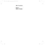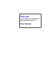
1
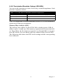
PCM-3680
2-Port CAN-Bus PC/104 Module
with Isolation Protection
User Manual
Copyright
The documentation and the software included with this product are copyrighted 2011 by Advantech Co., Ltd. All rights are reserved. Advantech
Co., Ltd. reserves the right to make improvements in the products
described in this manual at any time without notice. No part of this manual may be reproduced, copied, translated or transmitted in any form or
by any means without the prior written permission of Advantech Co., Ltd.
Information provided in this manual is intended to be accurate and reliable. However, Advantech Co., Ltd. assumes no responsibility for its use,
nor for any infringements of the rights of third parties, which may result
from its use.
Acknowledgements
Intel and Pentium are trademarks of Intel Corporation.
Microsoft Windows is a registered trademark of Microsoft Corp.
All other product names or trademarks are properties of their respective
owners.
Part No. 2003368050
1st Edition
Printed in Taiwan
June 2011
PCM-3680 User Manual
ii
Product Warranty (2 years)
Advantech warrants to you, the original purchaser, that each of its products will be free from defects in materials and workmanship for two years
from the date of purchase.
This warranty does not apply to any products which have been repaired or
altered by persons other than repair personnel authorized by Advantech,
or which have been subject to misuse, abuse, accident or improper installation. Advantech assumes no liability under the terms of this warranty as
a consequence of such events.
Because of Advantech’s high quality-control standards and rigorous testing, most of our customers never need to use our repair service. If an
Advantech product is defective, it will be repaired or replaced at no
charge during the warranty period. For out-of-warranty repairs, you will
be billed according to the cost of replacement materials, service time and
freight. Please consult your dealer for more details.
If you think you have a defective product, follow these steps:
1.
Collect all the information about the problem encountered. (For
example, CPU speed, Advantech products used, other hardware
and software used, etc.) Note anything abnormal and list any
onscreen messages you get when the problem occurs.
2.
Call your dealer and describe the problem. Please have your manual, product, and any helpful information readily available.
3.
If your product is diagnosed as defective, obtain an RMA (return
merchandize authorization) number from your dealer. This allows
us to process your return more quickly.
4.
Carefully pack the defective product, a fully-completed Repair and
Replacement Order Card and a photocopy proof of purchase date
(such as your sales receipt) in a shippable container. A product
returned without proof of the purchase date is not eligible for warranty service.
5.
Write the RMA number visibly on the outside of the package and
ship it prepaid to your dealer.
iii
CE
This product has passed the CE test for environmental specifications
when shielded cables are used for external wiring. We recommend the use
of shielded cables. This kind of cable is available from Advantech. Please
contact your local supplier for ordering information.
FCC Class A
This equipment has been tested and found to comply with the limits for a
Class A digital device, pursuant to Part 15 of the FCC Rules. These limits
are designed to provide reasonable protection against harmful interference when the equipment is operated in a commercial environment. This
equipment generates, uses and can radiate radio frequency energy and, if
not installed and used in accordance with the instruction manual, may
cause harmful interference to radio communications. Operation of this
equipment in a residential area is likely to cause harmful interference in
which case the user will be required to correct the interference at his own
expense.
Safety Precaution - Static Electricity
Follow these simple precautions to protect yourself from harm and the
products from damage.
1.
To avoid electrical shock, always disconnect the power from your
PC chassis before you work on it. Don't touch any components on
the CPU card or other cards while the PC is on.
2.
Disconnect power before making any configuration changes. The
sudden rush of power as you connect a jumper or install a card may
damage sensitive electronic components.
PCM-3680 User Manual
iv
Technical Support and Assistance
Step 1. Visit the Advantech web site at www.advantech.com/support
where you can find the latest information about the product.
Step 2. Contact your distributor, sales representative, or Advantech's customer service center for technical support if you need additional
assistance. Please have the following information ready before
you call:
- Product name and serial number
- Description of your peripheral attachments
- Description of your software (operating system, version, application software, etc.)
- A complete description of the problem
- The exact wording of any error messages
Packing List
Before setting up the system, check that the items listed below are
included and in good condition. If any item does not accord with the
table, please contact your dealer immediately.
• PCI communication interface card
• Industrial Communication Driver, Utility and PCI communication card
user's manual in ICOM CD-ROM
v
PCM-3680 User Manual
vi
Contents
Chapter
1 Introduction ..................................................... 2
1.1
1.2
1.3
1.4
Chapter
Description ........................................................................ 2
1.1.1
1.1.2
Features ............................................................................. 2
Specifications .................................................................... 3
Ordering Information ........................................................ 3
2 Hardware Installation..................................... 6
2.1
2.2
Initial Inspection................................................................ 6
Jumper Locations & Setting.............................................. 7
2.2.1
2.2.2
2.2.3
2.3
Chapter
Card Installation .............................................................. 12
Advantech Device Manager Installation ......................... 14
4 Software Requirements ................................ 22
4.1
Introduction ..................................................................... 22
4.2
4.3
Overall Description ......................................................... 22
Specific Requirements..................................................... 23
4.1.1
4.1.2
4.3.1
4.3.2
4.3.3
Chapter
Figure 2.1:PCM-3680 Silk Screen ................................. 7
Card Configuration ........................................................ 7
Switch and Jumper Functions ........................................ 8
Figure 2.2:IRQ Settings ................................................. 8
Terminator Resistor Setup (JP5/JP6) ............................. 9
Table 2.1:PCM-3680 Terminator Resistor Reference ... 9
Table 2.2:Memory Address Configuration .................. 10
Table 2.3:Memory Area ............................................... 11
3 Driver Installation......................................... 14
3.1
Chapter
Controller Area Network ............................................... 2
Optical Isolation Protection ........................................... 2
Definitions, Acronyms, and Abbreviations ................. 22
Reference ..................................................................... 22
Device Driver Functionality ........................................ 23
The CAN Driver Framework ....................................... 23
Figure 4.1:AdsCan.dll architecture .............................. 23
Software Interfaces ..................................................... 24
Table 4.1:Function Table of AdsCAN.dll ................... 24
5 Pin Assignments and Wiring ....................... 28
5.1
Pin Assignments.............................................................. 28
5.2
Wiring.............................................................................. 28
Figure 5.1:PCM-3680 pin assignments ....................... 28
Table 5.1:PCM-3680 Pin Wiring and Description ...... 28
Appendix A Register Format............................................. 30
A.0.1
A.0.2
CAN Controller Address Allocation ............................ 30
Register Descriptions ................................................... 34
vii
PCM-3680 User Manual
viii
CHAPTER
1
2
Introduction
This chapter provides a general
description of the PCM-3680.
Sections include:
• Description
• Features
• Specifications
• Ordering Information
Chapter 1 Introduction
1.1 Description
PCM-3680 is a special purpose communication card that brings the Control Area Network to your PC. With the built-in CAN controller, the
PCM-3680 provides bus arbitration and error detection with automatic
transmission repeat function. The onboard CAN controllers are located at
different positions in the memory. You can run both CAN controllers at
the same time, independently. The PCM-3680 operates at baud rates up to
1 Mbps and can be installed directly into the expansion slot of your PC.
1.1.1 Controller Area Network
CAN is a serial bus system suited for networking "intelligent" I/O devices
as well as sensors and actuators within a machine or plant. Characterized
by its multi-master protocol, real-time capability, error correction, high
noise immunity, and the existence of many different silicon components,
the CAN serial bus system, originally developed by Bosch for use in
automobiles, is increasingly being used in industrial automation.
1.1.2 Optical Isolation Protection
Onboard optical isolators protect your PC and equipment against damage
from ground loops, increasing system reliability in harsh environments.
1.2 Features
• Operates 2 CAN networks simultaneously
• High speed transmission (up to 1Mbps)
• 16 MHz CAN controller frequency
• 4 KB address space, 40 base address adjustable in steps from C800H up
to EF00H
• Optical isolation protection of 2500 VDC
• Wide IRQ selection for each port includes: IRQ 3, 4, 5, 6,7, 9, 10, 11,
12, 15
• LED indicates transmit/receive status on each port
• Direct memory mapping enables speedy access
PCM-3680 User Manual
2
• Supports 32/64-bit WinXP/Vista/Win7, WinCE 5.0/6.0 and Linux
1.3 Specifications
• Bus Interface: PC/104 compliant
• Ports: 2
• Protocol: CAN 2.0 A/B
• Communication Controller: SJA-1000
• CAN Transceiver: 82C250
• Signal Support: CAN_H, CAN_L
• Memory Address: From C800H to EF00H
• IRQ: 3, 4, 5, 6, 7, 9, 10, 11,12, 15
• CAN Controller Frequency: 16 MHz
• Speed (bps): Up to 1 Mbps programmable transfer rate
• Isolation Protection: 2500 VDC
• Connector: 4 x 10 box pin header
• Power Consumption: 5 V @ 400 mA(Typical)
• Dimensions: 3.6" x 3.8" (90 x 96 mm)
• Operating Temperature: -40 ~ 85° C (refer to IEC 68-2-1, 2)
• Storage Temperature: -25 ~ 85° C
• Operating Humidity: 5 ~ 95% Relative Humidity, non-condensing
• Shipping Weight: 0.485 lb (0.22 kg)
1.4 Ordering Information
PCM-3680: 2-port CAN-bus PC/104 Module with Isolation Protection
3
Chapter 1
PCM-3680 User Manual
4
CHAPTER
2
2
Hardware Installation
This chapter covers inspection and
installation of hardware and drivers.
Sections include:
• Initial inspection
• Jumper locations & setting
• Card installation
Chapter 2 Hardware Installation
2.1 Initial Inspection
You should find the following items inside the shipping package:
• PC/104 communication interface card
• Industrial Communication Driver, Utility and PCI communication card
user's manual in ICOM CD-ROM
PCM-3680 was carefully inspected mechanically and electrically before
it was shipped. It should be free of marks and scratches and in perfect
working order when received.
As you unpack the PCM-3680, check for signs of shipping damage (damaged box, scratches, dents, etc.). If it is damaged or it fails to meet specifications, notify our service department or your local sales representative
immediately. Also notify the carrier. Retain the shipping carton and packing material for inspection by the carrier. After inspection we will make
arrangements to repair or replace the unit.
When you handle the PCM-3680, remove it from its protective packaging
by grasping the rear metal panel. Keep the anti-vibration packing. Whenever you remove the card from the PC, store it in this package for protection.
Warning!
Discharge your body’s static electric charge by
touching the back of the grounded chassis of the
system unit (metal) before handling the board. You
should avoid contact with materials that hold a static
charge such as plastic, vinyl and Styrofoam. Handle
the board only by its edges to avoid static damage to
its integrated circuits. Avoid touching the exposed
circuit connectors. We also recommend that you use
a grounded wrist strap and place the card on a static
dissipative mat whenever you work with it.
PCM-3680 User Manual
6
2.2 Jumper Locations & Setting
Figure 2.1: PCM-3680 Silk Screen
2.2.1 Card Configuration
The PCM-3680 has two ports, each with one jumper. The jumpers set the
IRQ for the ports, which can be configured separately. A DIP switch sets
the memory base address for each port. The following chart shows the
function of the jumper and the switch (see the previous page for jumper
and switch locations).
7
Chapter 2
2.2.2 Switch and Jumper Functions
IRQ Setup:
JP1 Port 1
JP2 Port 2
Terminator Resistor Reference:
JP5 Port 1
JP6 Port 2
Memory base address:
SW1 Port 1, Port 2
Default Settings
• Port 1 is set for COM1 (IRQ=12, Memory address = DA00:0000).
• Port 2 is set for COM2 (IRQ=15, Memory address = DA00:0200).
If you need to change these settings, see the following sections. Otherwise, you can simply install the card.
Note that you will need to disable your CPU card's onboard COM ports,
if any, or set them to alternate addresses/IRQs.
Jumpers and Switches
Jumpers JP1 and JP2 set the interrupts for Port 1 and Port 2, respectively.
You can choose any IRQ from 3 to 15, except 8, 13 and 14. When you
choose IRQs, make sure they are not used for other cards in the system.
The following figures show the card's default settings.
Figure 2.2: IRQ Settings
PCM-3680 User Manual
8
2.2.3 Terminator Resistor Setup (JP5/JP6)
You can set the terminator resistor if necessary to match impedance. Each
port has a separate resistor.
Table 2.1: PCM-3680 Terminator Resistor Reference
Status
Value of Terminator Resistor (Ω)
Open mode
0
Close mode
120
Note: It is suggested to set the terminator resistor to 120 Ω to maintain a
satisfactory baud rate performance.
Memory Base Address (SW1)
The memory base address for the PCM-3680, which requires 4 KB of
address space, is made up of the memory segment and its associated offset. The address for the memory segment is set through SW1, a six-position DIP switch. You can choose any base address from C800 to EF00.
The following table shows the DIP switch settings and the corresponding
base addresses.
9
Chapter 2
Table 2.2: Memory Address Configuration
Address/ DIP Switch
A12
A13
A14
A15
A16
A17
C800H
on
on
on
off
on
on
C900H
off
on
on
off
on
on
CA00H
on
off
on
off
on
on
CB00H
off
off
on
off
on
on
CC00H
on
on
off
off
on
on
CD00H
off
on
off
off
on
on
CE00H
on
off
off
off
on
on
CF00H
off
off
off
off
on
on
D000H
on
on
on
on
off
on
D100H
off
on
on
on
off
on
D200H
on
off
on
on
off
on
D300H
off
off
on
on
off
on
D400H
on
on
off
on
off
on
D500H
off
on
off
on
off
on
D600H
on
off
off
on
off
on
D700H
off
off
off
on
off
on
D800H
on
on
on
off
off
on
D900H
off
on
on
off
off
on
DA00H
on
off
on
off
off
on
DB00H
off
off
on
off
off
on
DC00H
on
on
off
off
off
on
DD00H
off
on
off
off
off
on
DE00H
on
off
off
off
off
on
DF00H
off
off
off
off
off
on
E000H
on
on
on
on
on
off
E100H
of
on
on
on
on
off
E200H
on
off
on
on
on
off
E300H
off
off
on
on
on
off
E400H
on
on
off
on
on
off
E500H
off
on
off
on
on
off
E600H
on
off
off
on
on
off
PCM-3680 User Manual
10
Table 2.2: Memory Address Configuration
E700H
off
off
off
on
on
off
E800H
on
on
on
off
on
off
E900H
off
on
on
off
on
off
EA00H
on
off
on
off
on
off
EB00H
off
off
on
off
on
off
EC00H
on
on
off
off
on
off
ED00H
off
on
off
off
on
off
EE00H
on
off
off
off
on
off
EF00H
off
off
off
off
on
off
Memory Area
Once the memory segment for the base address is selected, the offset will
be automatically assigned for Port 1, Port 2, and hardware reset. The following table shows the base addresses of the CAN controllers.
Table 2.3: Memory Area
Base address (hex)
CAN Controller
base:0000h - base:00FFh
Basic- Port 1
base:0100h - base:01FFh
HW reset Basic - Port 1
base:0200h - base:02FFh
Basic- Port 2
base:0300h - base:03FFh
HW reset Basic - Port 2
base:0400h - base:0FFFh
Not used
11
Chapter 2
2.3 Card Installation
Note:
Make sure you have installed the driver before installing the
card. We strongly recommend that you install the software driver
before installing the hardware into your system, since this will
guarantee a smooth and trouble-free installation process.
Warning!
Turn off your PC’s power supply whenever you install or remove
the PC/104 communication card or its cables. Static electricity
can easily damage computer equipment. Ground yourself by
touching the chassis of the computer (metal) before you touch
any boards.
1. Turn off the computer.
2. Turn the power off to any peripheral devices (such as printers and
monitors).
3. Disconnect the power cord and any other cables from the back of the
computer.
4. Turn the PC if necessary to gain access to the cables.
5. Remove the PC’s cover (refer to your user’s guide if necessary).
6. Locate the expansion slots or passive back-plane (at the rear of the PC)
and choose any unused slot.
7. Remove the screw that secures the expansion slot cover to the PC (save
the screw to secure the interface card retaining bracket).
8. Remove the anti-vibration card clamp if supplied.
9. Carefully grasp the upper edge of the PC/104 communication card.
10. Align the hole in the retaining bracket with the hole on top of the
expansion slot.
11. Align the gold striped edge connector with the expansion slot socket.
12. Press the board firmly into the socket.
13. Replace the screw in the expansion slot’s retaining bracket.
14. Replace anti-vibration cardholder.
15. Replace the PC’s cover. Connect the cables you removed in step 3.
16. Turn the computer power on.The board is now installed in the computer. See Chapter 5 for information on cabling.
PCM-3680 User Manual
12
CHAPTER
3
2
Driver and Advantech
Device Manager
Installation
This chapter shows how to install the
driver and Advantech Device Manager.
Sections include:
• Driver Installation
Chapter 3 Driver Installation
3.1 Advantech Device Manager Installation
Advantech provides WDM CAN driver that allows you to configure your
hardware and store the settings in your Windows registry. You must
install the WDM CAN driver if you want to add and manage Advantech
CAN cards.
Please follow the steps below to install Advantech CAN WDM Driver.
1.
Select Complete and then Next to continue the installation.
PCM-3680 User Manual
14
2.
After a while, the installation will be complete.
3.
After the installation of the driver, start the “Add Hardware Wizard” to add the hardware device.
15
Chapter 3
4.
Then follow the steps as shown in the figures below.
PCM-3680 User Manual
16
17
Chapter 3
5.
Select the device driver:
6.
Select the AdvCanBus file:
PCM-3680 User Manual
18
7.
Select PCM-3680:
19
Chapter 3
Configuration
Before you start to use PCM-3680, you must configure the CAN
resource. You can refer to the below figures to set the Memory Address
and IRQ.
Set the Memory Address and IRQ that is not occupied by other add-on
devices.
PCM-3680 User Manual
20
CHAPTER
4
2
Software
Requirements
This chapter has information on the
software of PCM-3680.
Sections include:
• Introduction
• Overall Description
• Specific Requirements
Chapter 4 Software Requirements
4.1 Introduction
PCM-3680 is Isolated Dual-port CAN communication cards which provides two isolated CAN ports for communication applications in difficult
environments. The chip on the CAN cards is SJA1000. The SJA1000 is a
single chip solution for PC-based CAN port and parallel expansion add-in
cards.
This chapter outlines the CAN card’s windows DLL driver software
requirement specifications. Including functionality, performance, and
user interface requirements. It applies to programming the CAN cards
Windows unified DLL driver, including the driver for PCM-3680.
4.1.1 Definitions, Acronyms, and Abbreviations
SRS = Software Requirements Specification
PPI = Programmable Peripheral Interface
GUI = Graphics User Interface
4.1.2 Reference
Please see “SJA1000.pdf” on your CD-ROM for further information on
the SJA1000 chip.
4.2 Overall Description
In order to unify the driver interface of Advantech’s CAN series of products, a new DLL file named AdsCAN.dll has been defined. This makes it
possible to change the CAN card from PCM-3680 to PCL-841 without
recompiling applications.
AdsCAN.dll should decide which driver to call depending on the different CAN cards.
PCM-3680 User Manual
22
4.3 Specific Requirements
4.3.1 Device Driver Functionality
The AdsCAN.dll driver needs to decide which driver should be called
depending on different hardware.
The AdsCAN.dll driver should properly translate the function parameters
to a lower layer driver.
4.3.2 The CAN Driver Framework
All user-mode functionality is implemented through Win32 communication API Functions.
The AdsCan.dll unified driver interface for all CAN cards is shown in figure 4.1.
User's Application
AdsCAN.dll
Call CAN win32 API
Dynamic decide which
dll should be loaded
Ads841.dll
Ads1680.dll
Other CAN card dll
Ads841s.sys
Ads841s.vxd
Ads1680s.sys
Ads1680s.vxd
Other CAN card sys
Other CAN card vxd
PCL841 card
PCM-3680I card
Other CAN cards
Figure 4.1: AdsCan.dll architecture
With the new driver architecture, you don’t need to recompile your CAN
applications when you switch one CAN card with another.
23
Chapter 4
4.3.3 Software Interfaces
AdsCAN.dll should follow the CAN software-programming interface, so
that users can use Advantech’s driver software in the same way.
You can access the CAN functionality via the AdsCAN.dll Library as
shown in the following table. For detailed function library definitions and
descriptions please see the file ‘can.chm’ on the CD-ROM.
Path in CD-ROM: Documents\Software Manuals\CAN
Table 4.1: Function Table of AdsCAN.dll
Function
Syntax (in C)
Description
1
CANCheckEvent()
Check event status from kernelmode and clear event.
2
CANEnableEvent()
Enables or disables the event mechanism
3
CANEnableMessaging()
Select the data transmit interrupt
4
CANEnableRxInt()
Enable the receive interrupt
5
CANGetArbitrationLostCatchMsgEx()
Get arbitrate lost catch information
6
CANGetBaudRate()
Get the card current baud rate
7
CANGetControllerErrorCodeEx()
Get Controller error code
8
CANGetErrorMessage()
Get error message
9
CANGetEventName()
Queries and gets CAN port's event
name
10
CANGetProtocolType()
Get the card current protocol type
11
CANHwReset()
Reset the hardware
12
CANInit()
Controls CAN port settings
13
CANInpb()
Inputs a byte data from the specified
address on CAN card
14
CANOutpb()
Outputs a byte data to the specified
address on CAN card
15
CANPortClose()
Releases settings, close port
16
CANPortOpen()
Open the CAN port
17
CANQueryID()
Query the message ID
18
CANQueryMsg ()
Reads data from the card
PCM-3680 User Manual
24
Table 4.1: Function Table of AdsCAN.dll
19
CANReadFile()
Reads data
20
CANReset()
Resets CAN port
21
CANSendMsg()
Sends message
22
CANSetAcp()
Set the card 2.0 A protocol acceptance code
23
CANSetAcpEx()
Set 2.0B protocol accept code
24
CANSetBaud()
Set card baud rate
25
CANSetBufferPtr()
Set the data receive buffer
26
CANSetCountPtr()
Set the counter of receive buffer
27
CANSetIntrMaskEx()
Set 2.0B protocol interrupt mask
28
CANSetNormal()
Sets CAN card to normal mode
29
CANSetOutCtrl()
Set the card out control register
30
CANSetProtocolType()
Set the card current protocol type
31
CANWaitForFIFOEvent()
Wait for the FIFO buffer event.
32
CANWaitForID()
Wait For the message ID
33
CANWaitForMsg()
Queries and gets message from
CAN bus.
34
CANWakeUpEx()
Set Can controller into sleep mode
35
CANWriteFile()
Send message
25
Chapter 4
PCM-3680 User Manual
26
CHAPTER
5
2
Pin Assignments and
Wiring
This chapter covers the pin assignment
for the CAN connector, and the wiring
of the two transmission wires.
Sections include:
• Pin Assignments
• Wiring
Chapter 5 Pin Assignments and Wiring
5.1 Pin Assignments
Figure 5.1 shows the pin assignment for the card’s boxheader connectors
Figure 5.1: PCM-3680 pin assignments
5.2 Wiring
The CAN standard supports half–duplex communication. This means that
just two wires are used to transmit and receive data.
Table 5.1: PCM-3680 Pin Wiring and Description
PCM-3680( Boxheader)
Terminal( DB-9)
Pin
Signal
Pin
Signal
3
CAN_L
2
CAN_L
4
CAN_H
3
GND
5
GND
7
CAN_H
PCM-3680 User Manual
28
APPENDIX
A
2
Register Format
29
Appendix A
Appendix A Register Format
This appendix gives a brief description of the CAN controller registers.
For more detailed information, please refer to the Stand-alone CAN-controller Data Book from Philips Semiconductors Microcontroller Products.
A.0.1 CAN Controller Address Allocation
Philips PCX82C200 CAN Controller
ADDRESS
Register address map
PCM-3780 Series User Manual
30
31
Appendix A
PCM-3780 Series User Manual
#
TITLE
ADDRESS
7
6
5
4
Control Segment
Overrun Reserved Interrupt Enable
Error Interrupt Enable
Clear Reserved Go to Sleep Overrun Status
Transmissi
Transmit Receive on Status
Status
Complete Status
Wake‐Up Overrun Reserved
Interrupt Interrupt
0
Test Mode
Sync
2
Command Register
1
Reserved
Reserved
3
Status Register
2
Bus Status
Error Status
3
Reserved
Reserved
4
AC.7
AC.6
AC.5
AC.4
5
AM.7
AM.6
AM.5
AM.4
32
1
Control Register
4
5
6
Interrupt Register
Acceptance Code Register
Acceptance Mask Register
3
2
1
0
Transmit Receive Reset Interrupt Interrupt Request
Enable
Enable
Release Abort Transmissi
Receive Transmissi
on Request
Buffer
on
Transmit Buffer Access
Data Overrun
Receive Buffer Status
Error Interrupt
Transmit Interrupt
Receive Interrupt
AC.3
AC.2
AC.1
AC.0
AM.3
AM.2
AM.1
AM.0
7
8
9
10
Bus Timing Register 0
Bus Timing Register 1
Output Control Register
Test Register (note 1)
SJW.1
SJW.0
BRP.5
BRP.4
BRP.3
BRP.2
BRP.1
BRP.0
7
SAM
TSEG2.2
TSEG2.1
TSEG2.0
TSEG1.3
TSEG1.2
TSEG1.1
TSEG1.0
8
OCTP1
OCTN1
OCPOL1
OCTP0
OCTN0
OCPOL0
9
Reserved
Reserved
10
ID.10
ID.9
ID.8
ID.7
ID.6
11
ID.2
ID.1
ID.0
RTR
12‐19
Data
Data
Data
Data
33
6
11
Identifier
RTR, Data Length Code
Bytes 1‐8
Access Map Connect RX Connect TX Internal Internal Buffer 0 Buffer CPU
Bus
Register
CPU
Transmit Buffer
OCMODE1 OCMODE0
Normal RAM Conncet
Float Output Driver
ID.5
ID.4
ID.3
DLC.3
DLC.2
DLC.1
DLC.0
Data
Data
Data
Data
Receive Buffer 0/1
Appendix A
12
Identifier
RTR, Data Length Code
Bytes 1‐8
20
ID.10
ID.9
ID.8
ID.7
ID.6
ID.5
ID.4
ID.3
21
ID.2
ID.1
ID.0
RTR
DLC.3
DLC.2
DLC.1
DLC.0
22‐29
Data
Data
Data
Data
Data
Data
Data
Data
A.0.2 Register Descriptions
Control Register (CR)
The Control Register is used to change the behavior of the PCX82C200.
Control bits may be set or reset by the attached microcontroller, which
uses the Control Register as a read/write memory.
Command Register (CMR)
A command bit initiates an action within the transfer layer of the
PCX82C200. If a read access is performed to this address, the byte
11111111 (binary) is returned.
Status Register (SR)
The Status Register reflects the status of the PCX82C200 bus controller.
The Status Register appears to the microcontroller as a read-only memory.
Interrupt Register (IR)
The Interrupt Register allows identification of an interrupt source. When
one or more of this register's bits are set, the INT pin is activated. All bits
are reset by the PCX82C200 after this register is read by the microcontroller. This register appears to the microcontoller as a read-only memory.
Acceptance Code Register (ACR)
The Acceptance Code Register is part of the acceptance filter of the
PCX82C200. This register can be accessed (read/write) if the Reset
Request bit is set HIGH (present). When a message which passes the
acceptance test is received and if there is an empty Receive Buffer, then
the respective Descriptor and Data Field are sequentially stored in this
empty buffer. In the case that there is no empty Receive Buffer, the Data
Overrun bit is set HIGH (overrun).
Acceptance Mask Register (AMR)
The Acceptance Mask Register is part of the acceptance filter of the
PCX82C200. This register can be accessed (read/write) if the Reset
Request bit is set HIGH (present). The Acceptance Mask Register classifies the corresponding bits of the acceptance code as “relevant” or “don't
care” for acceptance filtering.
PCM-3780 Series User Manual
34
Bus Timing Register 0 (BTR0)
The Bus Timing Register 0 defines the values of the Baud Rate Prescaler
(BRP) and the Synchronization Jump Width (SJW). This register can be
accessed (read/write) if the Reset Request bit is set HIGH (present).
Bus Timing Register 1 (BTR1)
The Bus Timing Register 1 defines the length of the bit period, the location
of the sample point, and the number of samples to be taken at each sample
point. This register can be accessed (read/write) if the Reset Request bit is
set HIGH (present).
Output Control Register (OCR)
The Output Control Register allows, under software control, the setup of
different driver configurations. This register may be accessed (read/write)
if the Reset Request bit is set HIGH (present).
Test Register (TR)
The Test Register is used only for production testing.
Transmit Buffer
The Transmit Buffer stores a message from the microcontroller to be transmitted by the PCX82C200. It is subdivided into the Descriptor and Data
Field. The Transmit Buffer can be written to and read from by the microcontroller.
Receive Buffer
The layout of the Receive Buffer and the individual bytes correspond to
the definitions given for the Transmit Buffer layout, except that the
addresses start at 20 instead of 10.
35
Appendix A
PCM-3780 Series User Manual
36