1
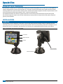
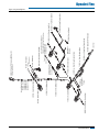
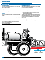
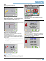
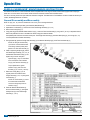
DYNAJET FLEX
INSTALLATION, SETUP AND USER GUIDE
Software Version 1.01
Copyrights
© 2015 TeeJet Technologies. All rights reserved. No part of this document or the computer programs described in it may be reproduced,
copied, photocopied, translated, or reduced in any form or by any means, electronic or machine readable, recording or otherwise, without
prior written consent from TeeJet Technologies.
Trademarks
Unless otherwise noted, all other brand or product names are trademarks or registered trademarks of their respective companies or
organizations.
Limitation of Liability
TEEJET TECHNOLOGIES PROVIDES THIS MATERIAL “AS IS” WITHOUT WARRANTY OF ANY KIND, EITHER EXPRESSED OR
IMPLIED. NO COPYRIGHT LIABILITY OR PATENT IS ASSUMED. IN NO EVENT SHALL TEEJET TECHNOLOGIES BE LIABLE FOR ANY
LOSS OF BUSINESS, LOSS OF PROFIT, LOSS OF USE OR DATA, INTERRUPTION OF BUSINESS, OR FOR INDIRECT, SPECIAL,
INCIDENTAL, OR CONSEQUENTIAL DAMAGES OF ANY KIND, EVEN IF TEEJET TECHNOLOGIES HAS BEEN ADVISED OF SUCH
DAMAGES ARISING FROM TEEJET TECHNOLOGIES SOFTWARE.
Safety Information
TeeJet Technologies is not responsible for damage or physical harm caused by failure to adhere to the following safety
requirements.
As the operator of the vehicle, you are responsible for its safe operation.
The DynaJet Flex is not designed to replace the vehicle’s operator.
Be sure that the area around the vehicle is clear of people and obstacles before and during engagement.
The DynaJet Flex is designed to support and improve efficiency while working in the field. The driver has full responsibility for the quality and
work related results.
DynaJet Flex
Table of Contents
DYNAJET FLEX OVERVIEW
2
INSTALLATION 2
CONSOLE2
INSTALLATION 4
Dynajet Drivers ................................................................................................................................................................................................4
Power...................................................................................................................................................................................................................4
Nozzle Harnesses.............................................................................................................................................................................................4
Pressure Sensor Interface Kit.......................................................................................................................................................................5
Boom Interface Module (BIM).....................................................................................................................................................................5
DynaJet Interface.............................................................................................................................................................................................5
CAN Cables & Terminators............................................................................................................................................................................5
INITIAL STARTUP
6
Favorites..............................................................................................................................................................................................................6
Setup....................................................................................................................................................................................................................6
Units..........................................................................................................................................................................................7
Number of Sections..................................................................................................................................................................7
Maximum Pressure Sensor Value............................................................................................................................................7
Nozzle Selection...............................................................................................................................................................................................7
Select Nozzle Series.........................................................................................................................................................7
Select Nozzle Capacity.....................................................................................................................................................7
Ready to Pressure Test the System............................................................................................................................................................8
Work Screen.......................................................................................................................................................................................................8
Droplet Size Chart............................................................................................................................................................8
On Screen Indicators................................................................................................................................................................8
USER SETTINGS
9
OEM Settings.................................................................................................................................................................................................. 10
TUNING DYNAJET
11
DYNAJET NOZZLE SELECTION
12
Nozzle Selection Example......................................................................................................................................................................... 13
55295 E-CHEMSAVER® MAINTENANCE INSTRUCTIONS
14
General Disassembly and Reassembly................................................................................................................................................. 14
APPLICATION RATES AT GIVEN SPEED
15
98-05334-EN R1
1
DynaJet Flex
DYNAJET FLEX OVERVIEW
The DynaJet Flex controller works in conjunction with an existing rate controller that regulates flow via a control valve or pump regulation to
achieve a target application rate when a speed change occurs. This system only works with automatic rate controllers that use flow based
monitoring systems and not pressure based monitoring systems. Automatic rate controllers equipped for both flow and pressure based control
should have the pressure-based system disabled to work in conjunction with DynaJet Flex.
The independent automatic rate controller loop performs the same as it would if the DynaJet controller were not present. The DynaJet
Flex controller changes flow output to each individual nozzle based upon input provided from the operator about the optimum droplet size
(pressure) for the application.
INSTALLATION
CONSOLE
The DynaJet Flex console is designed to provide years of service under typical agricultural operating conditions. A tight fitting enclosure
means that typical dusty environments will not cause operational problems. While occasional splashing of water will not damage the unit, the
DynaJet Flex console is not designed for direct exposure to rain. Take care not to operate the DynaJet Flex console in wet conditions.
Figure 1: DynaJet Flex 7120 Console Front and Back
Power Switch
Bright Touch Screen
USB Port
to DynaJet Interface
Harness Connection
Standard RAM Bracket
2
www.teejet.com
45-05855 - CAN Terminator, Female (Start)
78-05122 - DynaJet Driver
45-05980-xx Driver to Power
“Y” Cable
45-05965 - CAN to Bulkhead Cable
45-05963 - CAN Bulkhead Cable
78-05106 - DynaJet Interface
45-10148 - Sentry Interface Harness
Console Extension Cable
45-05900: 5' / 1.5 m
45-05901: 10' / 3 m
45-05902: 20' / 6 m
45-05903: 40' / 12 m
45-05935-20-xx Tip Harness
98-05334-EN R1
to Battery Power
45-05943 - Battery 60 AMP Fuse Cable
45-05942-xx - 6 Gauge Power Extension Cable
78-05121-xx - Power Distribution Module
35-50048 - DynaJet Solenoid
45-05948-xx - Solenoid Extension Cable
45-05936-xx - Tip Harness Extension
45-05856 - CAN Terminator, Male (End)
Kit includes: Interface, Sensor Cable, and Pressure Sensor
90-04007: 10' / 3 m
90-04008: 32' / 10 m
45-05971-xx - Driver to Power Extension Cable
45-058xx - CAN Extension Cable
Interface LED - Flashes until
CAN message is received,
then on steady
Sensor Cable
Pressure Sensor
DynaJet Pressure Sensor Interface Kit
78-05091 - Boom Interface Module (BIM)
45-10142 - BIM Harness
Boom Sense Wires
to 12v Power
401-0016 - Power Cable
Kit includes: Console and Mount
90-02887 - DynaJet 7120 Console w/RAM Mount Kit
DynaJet Flex
Figure 2: System Diagram
3
DynaJet Flex
INSTALLATION
Dynajet Drivers
Nozzle Harnesses
The DynaJet Drivers will mount on the boom at the end of each
section.
Each section will require Nozzle Harnesses designed for your
specific nozzle spacing and number of nozzles.
There will be one DynaJet Driver 78-05122 per boom section with a
limit of 20 nozzles per section.
• Mount them so they are at the end of each section that is
closest to the middle of the boom.
Power
Power will be sourced from the battery using the 60amp fused cable
45-05943.
Power from the battery will be routed to the boom using the 6 gauge
power cables 45-05942-xx
The Power Distribution Modules 78-05121-xx will connect to the
45-05942-xx cables.
When installing Nozzle Harnesses 45-05935-xx-xx always start with
Section 1 and continue to the last section.
• Nozzle harnesses are built with an even number of outputs.
• Some sections will use more than one harness to equal the
number of nozzles in that section.
The yellow and white solenoid cables on the nozzle harnesses must
alternate across the entire boom. When sections have odd numbers
of nozzles then accounting for the altering can be accomplished
one of two ways:
a.By crossing the two solenoid cables
b.By installing Nozzle Harness Reversing Adapters 45-05952
Power will then route from 78-05121-xx to each DynaJet Driver
78-05122 using cables 45-05971-xx.
Figure 3: Installation Diagram
Power Distribution Module
to CAN connection
DynaJet Driver
Tip Harness
DynaJet Solenoids
4
www.teejet.com
DynaJet Solenoids
DynaJet Flex
Pressure Sensor Interface Kit
The DynaJet system requires one Pressure Sensor Interface Kit
90-04007 or 98-04008 to be installed.
• The Pressure Sensor Interface Kit should be mounted close the
boom manifold.
Boom Interface Module (BIM)
DynaJet Interface
The DynaJet Interface 78-05106 connects to the Sentry Interface
Harness 45-10148:
The Sentry Interface Harness connects to
a.The Console 75-30119 (extension cable may be used)
b.Power 12V for powering the CAN
The Boom Interface Module (BIM) 78-05091 is used by the DynaJet
System for boom sense.
The BIM Harness connects between the BIM and the CAN.
On the BIM Harness 45-10142, the Boom Sense Wire (or flying
leads) are supplied to tie into existing machine harnesses or
switches.
If not using the BIM Harness, some machine specific harnesses are
available.
The BIM can be mounted in the cab or outside depending upon your
installation.
c.CAN
d. BIM Harness
The DynaJet Interface can be mounted in the cab or outside
depending upon your installation.
CAN Cables & Terminators
The Start Terminator 45-05855 must be connected to the DynaJet
Driver 78-05122 for Section 1.
CAN cables must be connected in series:
a.To each DynaJet Driver 78-05122
b.To the Boom Interface Module 78-05091 (via BIM Harness
45-10142)
c. To the DynaJet Interface 78-05106 (via Sentry Interface
Harness 45-10148)
d.To the Pressure Sensor Interface Kir (via Pressure Interface
78-05110)
The End Terminator 45-05856 must be connected to the Driver
Module 78-05122 for the last section.
DynaJet Driver
Tip Harness
DynaJet Solenoids
DynaJet Solenoids
DynaJet Driver
Tip Harness
DynaJet Solenoids
DynaJet Solenoids
DynaJet Driver
Tip Harness
DynaJet Solenoids
CAN Start Terminator
(female)
at Boom Section 1
DynaJet Solenoids
98-05334-EN R1
5
DynaJet Flex
INITIAL STARTUP
This section will explain basic setup of the values required for first-time setup of a DynaJet Flex system.
When these settings are completed, initial operation and fine-tuning should be possible.
To access setup menu from the work screen, touch center of the screen.
Figure 4: Options Menu
1. Select from:
►Favorites – The FAVORITE icon
represents favorite spray
nozzles. This function automatically stores the most recent
five (5) nozzles chosen. Use this to quickly access your most
frequently used spray nozzles.
is used to access settings. This
►Setup – The SETUP icon
will enter the configuration menu.
►Nozzle Selection – The SPRAY Nozzle icon
is used to
select the spray nozzle style and capacity. Once chosen here,
the spray nozzle style and capacity is automatically added to
the favorites list.
2. Press HOME icon
to return to the main work screen.
Favorites
Setup
Figure 5: Favorites
NOTE: Not all settings are listed below. See “User Settings” section
of this guide for additional settings and details.
The favorite icon represents favorite spray nozzles. This
function automatically stores the most recent five (5) nozzles
chosen. Use this to quickly access your most frequently used spray
nozzles.
he setup icon is used to access settings. This will enter the
T
configuration menu. Selections are automatically saved when
adjusted.
Figure 6: Setup
Change Value
Work
Screen
6
www.teejet.com
Work
Screen
Previous
Page
Next
Page
DynaJet Flex
Units
Figure 10: Nozzle Selection
Sets the units to US (psi) or Metric (bar)
Figure 7: Units
Number of Sections
Set the number of boom sections. This should match the number of
sections used on the spray controller. Range is 1 to 15.
Select Nozzle Series
Use the green up and down arrows to highlight the correct spray
nozzle series/family.
Figure 11: Select Nozzle Series
Figure 8: Number of Sections
Maximum Pressure Sensor Value
Verify this value by looking at the pressure sensor description.
Values will be either 10 bar or 25 bar.
If pressure value displayed on the DynaJet Flex console are not
accurate compared to a mechanical gauge, adjust this value until
there is a match.
Select Nozzle Capacity
With the correct nozzle capacity highlighted, select the HOME icon
to return to operating mode. The selected nozzle will be active
and will automatically be added to the favorites list.
Figure 12: Select Nozzle Capacity
►Increasing the value will reduce the pressure value displayed
during operation
►Decreasing this value will increase the pressure value
displayed during operation
Figure 9: Max. Pressure Sensor Value
Nozzle Selection
Accesses the nozzle selection process to select which nozzle
is to be used. At this time only TeeJet nozzles are supported.
98-05334-EN R1
7
DynaJet Flex
Ready to Pressure Test the System
1. Ensure that current rate control system is operating at the
optimum level. Set DynaJet operating mode to manual and set
PWM duty cycle at 100%. This will make the system operate as if
DynaJet was not present. Use this configuration to verify the rate
control system is operating normally.
2. Keep DynaJet operating mode on manual and change PWM
duty cycle to 50%. Use this configuration to verify the rate control
system is operating normally.
3. Confirm boom section functionality by observing the row of
rectangles below the on the operating display.
5. Start pump and ensure no leaks.
6. Verify pressure on mechanical gauge matches the digital
pressure display within reason. If not, adjust max. pressure
sensor value as previously described.
7. Configure in PWM mode DynaJet at duty cycle of 50%. Confirm
each e-ChemSaver (ECS) is pulsating.
At this point the system is functioning. Further details for fine-tuning
the system are available in the User Settings section of this guide.
4. Switch the master switch ON (on rate control or other boom
section control switches) and individual sections one at a time.
Make sure each section appropriately changes colour to blue.
With the master switch OFF, all active sections will be grey again.
Work Screen
On Screen Indicators
Figure 13: Work Screen
Current Droplet Size
PWM Duty Cycle
Current Droplet Size – Displays the current droplet size using both
the appropriate colour droplet icon and size letter code.
Actual Pressure
Boom Status
Current Nozzle
Selection
Pressure Guage
PWM Duty Cycle – Displays the current PWM duty cycle as a
percentage.
Actual Pressure – Displays the actual pressure.
Current Nozzle Selection – Displays the current selected nozzle.
Boom Sections
►Blue – turned on
►Empty – turned off
Pressure Guage
►Red Diamond – Actual pressure
Nozzle Mode
(Pressure)
Manual Mode
(PWM)
►Colours – Droplet size,
Droplet Size Selectors
(Nozzle Mode)
Operation Modes
Droplet Size Chart
When choosing a spray nozzle that produces droplet sizes in one
of the eight droplet size classification categories, it is important to
remember that a single nozzle can produce different droplet size
classifications at different pressures. A nozzle might produce medium
droplets at low pressures, while producing fine droplets as pressure
is increased.
Category
Symbol
Colour code
Extremely fine
XF
Violet
Very fine
VF
Red
Fine
F
Orange
Medium
M
Yellow
Coarse
C
Blue
Very coarse
VC
Green
Extremely coarse
XC
White
Ultra coarse
UC
Black
8
www.teejet.com
►Nozzle Mode (Pressure) – When the user changes the desired
drop sizes choices (via the droplet size selectors checkboxes)
the system will recalculate the desired pressure. It will then
adjust the PWM duty cycle to attempt to attain the desired
pressure in the system.
►Manual Mode (PWM) – The user can manually adjust the
PWM duty cycle to attempt to attain the desired pressure in
the system.
Droplet Size Selectors
►Red X and greyed out– Not selected
DynaJet Flex
USER SETTINGS
If there are questions concerning the setup of the DynaJet Flex, please contact your dealer or TeeJet Customer service representative
for clarification before operation. TeeJet Technologies is not responsible for misuse or incorrect operation of the system.
Setup is used to configure Units, Display Brightness, Key Beep, Number of Sections, Boom Section On/Off Beep, Maximum Presure Sensor
Value, Minimum Duty Cycle, Control Hold Delay, Fine Gain, Coarse Gain, and Coarse Gain On/Off.
Display Brightness
Maximum Pressure Sensor
Units
Minimum Duty Cycle
Sets the brightness level of the display. Range is 5% to 100% in 5%
increments.
Sets the units to US (psi) or Metric (bar).
Sets the value from the pressure sensor description. Either 10 bar or
25 bar.
Sets the minimum duty cycle to which the DynaJet will control.
Default is 30%, minimum is 20%.
Higher values reduce the overall control range of the system.
Key Beep
Enable/disable all beeping from console.
Control Hold Delay
When any boom switch changes state, DynaJet Flex will not make
control adjustments for the specified time period. Range is 0.0 to
10.0 seconds. Default is 1.0 second.
Number of Sections
Set the number of boom sections. Range is 1 to 15.
Fine Gain
Boom Section On/Off Beep
Enable/disable beep when a boom section is turned on or off.
Allows the control system to make minor adjustments when close to
the target, with the goal of stable pressures and minimal overshoot of
target. Range is 0 to 100. Default is 30.
Fine gain settings are 1/10 as powerful gain as coarse gain settings.
98-05334-EN R1
9
DynaJet Flex
Coarse Gain
This is the more aggressive gain setting and will have the largest
impact on the stability and function of the DynaJet Flex system.
Coarse gain makes major adjustments to duty cycle to attempt to
bring actual pressure back to the target. A Coarse Gain setting that is
too high will result in pressure oscillation. Range is 1 to 100. Default
is 5.
Coarse Gain On
This setting determines the threshold at which Coarse Gain becomes
active. Value is shown in the pressure units previously chosen (bar or
PSI). Range is 0.07 to 1.38 bar.
For example, if operating in PSI units with a setting of 7; coarse gain
becomes active when actual pressure is 7 or more PSI away from
the target value. Increasing this value makes the Coarse setting in
effect less of the time (higher value means higher tolerance between
actual pressure and target pressure). Decreasing this value means
coarse regulation is active more frequently. Setting coarse gain ON
too high would disable the feature. Decreasing this value too much
will result in pressure oscillations.
Coarse Gain Off
This setting determines the threshold at which coarse regulation
is switched OFF and fine regulation takes over. Value is shown
in the pressure units previously chosen (bar or PSI). Range
is 0.07 to 1.38 bar (1 to 20 psi).
This value must be lower than coarse gain ON. For example, if
operating in PSI units and with a setting of 4; coarse regulation
will be switched OFF (and Fine Gain becomes active) when the
difference between target and actual pressure is 4 psi or less.
Regulation will remain in Fine until the error reaches the Coarse Gain
On value described above.
10
www.teejet.com
OEM Settings
The settings described below are engineering and development
values used in development of the DynaJet Flex system. Do not
alter these settings unless directed by TeeJet Technologies support
personnel.
Setting Description
Default Value
PWM Frequency
10 Hz
On Impulse duration
38
Hold current frequency
10 counts
Hold current duty cycle
5 counts
Phase offset
128 counts
Jump Point
5 psi or 0.35 bar.
Max. Duty Cycle
80% (all ON above this value)
DynaJet Flex
TUNING DYNAJET
1. Identify the speed range, rate range and system pressures for the application. Ensure the operating conditions are compatible with the
nozzle capacity, speeds and duty cycles shown in the TeeJet PWM nozzle selection guide.
2. Using the identified speed range based on nozzle selection use the rate controllers test speed or simulated speed to target a desired
application rate and droplet size.
3. Fine tune the regulation performance of the rate control system and the DynaJet system.
a.Typical settings used for DynaJet fine-tuning include Fine Gain, Coarse Gain, Coarse Gain On and Coarse Gain Off.
b.Coarse Gain On must be a higher value than coarse gain Off. A good starting point for Coarse Gain On is a pressure value that is
about 35-40% of the target pressure.
c. Coarse Gain Off value is typically is about 25% of the target pressure, or 5-10 PSI (0.3 - 0.6 bar) lower than Coarse Gain On.
d.Coarse Gain On and Coarse Gain % are used to make major adjustments to pressure regulation. Once coarse gain has brought
pressure near target; Coarse Gain Off and Fine Gain will influence the smaller adjustments.
e.Coarse Gain should be increased if large pressure adjustments need to be made more quickly.
f. Fine Gain should be decreased if actual pressure constantly moves across the target pressure.
DynaJet and the existing rate controller are two control systems that must coexist. Because DynaJet is a second control device that is
installed on the same liquid system, users should be prepared to adjust the rate controller regulation settings to harmonize the two system.
For example, if subtle changes in duty cycle on DynaJet induce noticeable rate or pressure oscillations, the rate control regulation gain
settings may need to be reduced. Placing the rate control system in manual regulation mode during the tuning process will help determine if
oscillations are being caused by the DynaJet or by the rate controller.
TeeJet control systems like 844E, 854 or Radion will typically perform better with DynaJet when their coarse and fine regulating speeds are
reduced by 2-3 digits.
General rule of thumb under normal operating conditions for flow rate changes; DynaJet in combination with the rate controller should have
rate/pressure stabilized in ~ 2-3 seconds.
98-05334-EN R1
11
DynaJet Flex
DYNAJET NOZZLE SELECTION
Selection of the proper spray nozzle for use with the DynaJet system is much like selecting the spray nozzle for a traditional spraying operation.
Along with the extra application flexibility, DynaJet brings a few other nozzle-related considerations that will be summarized below.
1. Duty cycle
a. DynaJet Flex controls nozzle flow rate by varying the portion of time that each nozzle is ‘on’ vs. ‘off’. The on time is referred to as Duty
Cycle. The range of Duty Cycle available is typically 30% to 100%, meaning that the nozzles on the machine will have the approximately
30% to 100% of their rated flow capacity.
b. With the DynaJet system:
Spray Nozzle Flow Capacity = Spray Nozzle Size x Duty Cycle
c. By varying the duty cycle, the DynaJet Flex is essentially varying spray nozzle capacity on the fly. When more pressure is required, the
nozzle capacity (duty cycle) is reduced. When higher nozzle capacity is required, the duty cycle is increased.
d.Although the operator has a much more flexible and forgiving application system with DynaJet, care should be taken to select spray
nozzles that give the best possible results.
e.When selecting a spray nozzle, review the DynaJet nozzle selection charts and select a spray nozzle capacity that produces the
target application rate at a duty cycle of about 70% when running at expected travel speeds. In other words, choose nozzle capacity
and desired pressure/droplet size closer to the high end of the speed (or rate) range than to the lower end. This will provide plenty of
adjustment range for DynaJet to reduce duty cycle when travel speed slows, while also providing additional capacity if travel speed
increases above the planned speed.
i.The default setting for minimum duty cycle is 30%. This means the system will not adjust the duty cycle below 30% ‘on’. While this
setting can be set as low as 20% by the operator, the higher default value provides a more uniform application at lower speeds.
2. Spray Nozzle Selection
a. The DynaJet system is not compatible with air inducted spray nozzles. Be sure to select a conventional spray nozzle for use with the
system. The recommended options are XR TeeJet, DG TeeJet, Turbo TwinJet and Turbo TeeJet.
b. Different nozzle styles have different droplet size characteristics across the range of operating pressures. The spray nozzle style should be
selected based on the desired droplet size at the pressures expected to be in use for your application.
c. Always use spray nozzles with 110° (or wider) spray pattern. These spray nozzle part numbers will typically include the 110 in their name –
for example TT11006VP or XR11006-VS. 80° spray nozzles are not recommended with DynaJet.
3. Spray Height
a. In order to achieve the best possible spray coverage, make sure to keep spray height at or above 20″ from the nozzle to the target.
12
www.teejet.com
DynaJet Flex
Nozzle Selection Example
These columns show flow rates at various
pressures. The Delta P represents pressure
loss through the DynaJet solenoid valve, and
the resulting Nozzle PSI and Flow show actual
values at the spray nozzle.
These columns show droplet
sizes for different styles
of spray nozzle at given
pressures. Use these columns
to choose the best nozzle
style for your application.
Just like a normal nozzle chart, these columns show rates available
at given speeds. The only difference is the range of values that
corresponds to the range of flows available with DynaJet flex.
If the operator wants to apply 15 GPA at 10 MPH, he would look in the 10 MPH column, and find the row that shows 15 GPA with room above and below to compensate for higher
and lower speeds that may be experienced in the field. In this case a TT11006 at 40-50 PSI will work very well.
The next consideration is droplet size. The chart shows that a Turbo TeeJet (TT) nozzle will give Very Coarse (VC) droplets in this pressure range, and a Turbo TwinJet (TTJ60) will
give Coarse (C) droplets. The benefit of the TT is that the operator could select droplets from VC to M all at the same rate and speed.
98-05334-EN R1
13
DynaJet Flex
55295 E-CHEMSAVER® MAINTENANCE INSTRUCTIONS
The 55295 e-ChemSaver is a solenoid-actuated shutoff compatible with a wide range of TeeJet nozzle bodies equipped with a diaphragm
check valve. It can be used for end-of-boom nozzles as well as individual nozzle shutoff and PWM controls.
The valve is normally closed and opens when the solenoid is energized. The 55295 has a 2-Pin MetriPack connector molded into the body for
a clean, weather-tight electrical connection.
General Disassembly and Reassembly
NOTE: O-rings (8, 9, 10) should be handled with care as they can be damaged/deformed
1. Loosen and remove the Nylon Nut (4) and Stainless Steel Washer (5)
2. Separate the Coil Assembly (1) from the rest of the Tube/Plunger Assembly (2, 3, 6-11)
3. Remove the Locking Ring (11)
4. Using pliers to grip the Stainless Steel Interface Cap (7), loosen the Tube Sub-Assembly (2) using a 9/16″ (14 mm) or adjustable wrench.
Note a low-profile 9/16″ wrench is available from TeeJet using part number 97-00067.
All repairable parts should be accessible at this point. The Plunger Sub-Assembly (3), Stainless Steel Spring (6), and O-rings (8, 9, 10)
can be replaced without further disassembly
5. During reassembly, place the Plunger Sub-Assembly (3) and Stainless Steel Spring (6) in the Tube Sub-Assembly (2)
NOTE: The Plunger Sub-Assembly
(3) should be oriented with the black
insert facing outward (visible) when
placed in the Tube Sub-Assembly (2)
6. While compressing the Spring (6), thread
the Tube/Plunger Assembly (2, 3, 6-11) to
the Stainless Steel Interface Cap (7) and
tighten using a wrench and pliers
Optional: Apply 1 drop of Loctite Blue
243 to the threads of the Interface
Cap (7) and Tube Sub-Assembly (2)
Torque Specifications: tighten
Interface Cap (7) and Tube SubAssembly (2) to 12 in-lbs (1.36 N-m)
7. Return the Locking Ring (11) to its
original position and slide the Tube/
Plunger Assembly (2, 3, 6-11) through the
Coil Assembly (1)
NOTE: The Coil Assembly (1) should
be oriented with the MetriPack
connectors facing away from the
Interface Cap (7)
8. Place the Stainless Steel Washer (5)
above the Coil Assembly (1) and tighten
the Nylon Nut (4) to the Tube/Plunger
Assembly (2, 3, 6-11)
14
www.teejet.com
Figure 14: US
APPLICATION RATES AT GIVEN SPEED
DynaJet Flex
98-05334-EN R1
15
DynaJet Flex
Figure 15: Metric
16
www.teejet.com
D
Y
N
A
J
E
T
F
L
E
X
INSTALLATION, SETUP AND USER GUIDE
An innovative new product from TeeJet makes spraying more efficient and
more productive. The DynaJet Flex system uses a touch screen controller
and individual solenoids to control each spray nozzle. This innovative
system works along with an existing rate controller, and allows the operator
to choose specific droplet sizes that will be used for a particular job. The
rate controller manages application rate, and the DynaJet system uses
PWM technology to control system pressure and thereby control spray
droplet size. Droplet size data is built into the controller so setup is easy
and droplet sizes can be changed on the go. PWM control of each nozzle
delivers very large ranges of speeds and application rates with a single
spray nozzle and with consistent spray quality.
www.teejet.com
98-05334-EN-A4 R1 English
© TeeJet Technologies 2015