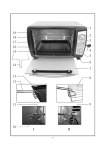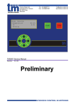
1
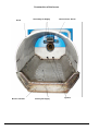
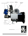
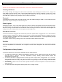
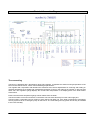
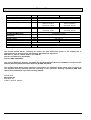
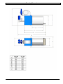
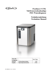
Datum 080708, rev 0
eurofire XL-GRYM
500, 700 kW
st
The Pellet Burner of the 21 Century
Ekosystem AB
Björkevägen 84, S-805 97 GÄVLE, Sweden
Table of Contents
General Information……………………………………………………………………………………………3
Read these instructions thoroughly before installing and starting the burner…………………………3
Guarantee………………………………………………………………………………………………….….3
Delivery Packing List Check…………...………………………………………………..…………………..3
Access and Free Space around the Burner......................................................................................3
Ashes...............................................................................................................................................3
Boiler Room Air Supply ...................................................................................................................3
Pellets ………………………………………………………………………………………………….……3
Installation..........................................................................................................................................4
Pellet storage and Feed Screw ........................................................................................................4
Design and internal structure............................................................................................................4
Temperature Gauge PID Regulator (standard) and Lambda Sensor ................................................4
Installation Instructions.....................................................................................................................5
Adjustments of the Burner ................................................................................................................8
Delivery Settings ..............................................................................................................................8
Chimney Draught .............................................................................................................................8
Negativ Pressure in Combustion Chamber ………………………………………………………….…. 8
Photocell .........................................................................................................................................8
Setting the Thermostats ...................................................................................................................8
Pellets Priming Measure ..................................................................................................................8
Start and Stopp the Burner...............................................................................................................8
Fuel Quantity and Pellets Travel Time to the Burner …………………………………………………… 9
Adjustment of Air Supply to the Burner ............................................................................................9
Maintenance and Service ................................................................................................................10
Cleaning the Burner .......................................................................................................................10
Photocell ........................................................................................................................................10
Electric Ignitiers..............................................................................................................................10
Back-burn Protection......................................................................................................................10
Sprinkler.........................................................................................................................................10
The Equipment’s Safety Systems...................................................................................................10
Electrical Connection Diagram………………………………………………………………….…………11
Connecting ....................................................................................................................................11
Technical Data ……………………………………………………………………………………………….12
Drowing/Dimensions ……………………………………………………………………………………….13
Installation Report ...........................................................................................................................14
Dealer, Name and Address ............................................................................................................14
Measured and Installed Settings ...................................................................................................14
Integral part of documentation of eurofire BIG burner is TM3007 User Manual - MPU Control Unit
Instruction.
Ekosystem AB reserves the right to make modifications to its equipment at any time
2
General Information
Read these instructions thoroughly before installing and starting the burner
Thank you for placing your trust and confidence in an Ekosystem AB product. We trust your experience of this
product will be one of total satisfaction, before you use this product please note the following:
For safe and fault free function it is of great importance that the burner is installed correctly and the
instructions for its installation and use are followed. If you are unsure about anything regarding installation
or you have any questions about equipment use contact your supplier for further details.
Installation must be performed by trained and experienced personnel. In the event of incorrect or
unauthorised installation the product guarantee offer from Ekosystem AB will be rendered null and void.
The enclosed guarantee certificate must be completed and sent to Ekosystem AB within ten days of
completion of installation. Any necessary electrical work must only be carried out by a qualified electrician.
In the event of any initial difficulties during start-up, please follow the trouble shooting guide in the
instruction manual. If, however, you can not find the problem, please contact your local eurofire retailer.
We recommend that customers inform their local chimney-sweep of any change of use of their chimney. It
is the user’s responsibility to ensure any local authority regulations are followed when using pellets firing
equipment.
Guarantee
Ekosystem AB offers a one-year guarantee against all manufacturing defects for the eurofire pellet burner and its
components. Items not covered by this guarantee are: the ignition element, damage caused by insufficient
maintenance, faulty handling or incorrect installation. This guarantee does not cover direct or indirect injuries to
third parties or damage to property.
Cost of labour for replacement of components is not included in the guarantee. Ekosystem AB will exchange new
components for defective components if returned to Ekosystem AB within 14 days of installation.
Ekosystem does not receive components sent by freight where the receiver must pay freight charges.
Delivery - Packing List check
Check the packing list and ensure there is no visible damage to the contents. Any damages must be notified
directly to the carrier. The carrier is insured for the transport of the burner. Ensure all listed parts are included in the
delivery and that they are undamaged.
Access and Free Space Around Burner
Building regulations and local bye-laws must be followed.
Ensure there is at least 0.5 metre free access space around the burner to facilitate service and maintenance.
Ashes
Store all ashes in a covered fire-proof container. Ashes can glow for several days! Do not keep combustible
materials in the vicinity of the boiler and burner. Keep boiler room clean and tidy to prevent fire risk.
Boiler Room Air Supply
Ensure the air-intake volume to the boiler room is equal to the chimney draught volume to the out-side air and it is
open. Pellet-heating when in operation requires more air supply than oil-heating operation.
Pellets
Pellets should be of good quality, free from sawdust and hard in consistency. The pellets must be manufactured
from clean and chemical free wood and should weigh between 650 – 700 kgs per cubic meter. The energy content
should be between 4.7 – 5.1 kWh/kg and the ash content should be no higher than 1%. Your pellets dealer will give
you details. Store the pellets in a dry place in able to retain their hard consistency. Pellets damaged by damp and
moisture will be soft and spongy. If these damaged pellets are used it could cause operational difficulties with the
burner equipment.
3
Installation
Pellet Store and Feed Screw
A feed-screw supplies the burner with fuel from an external fuel storage area. The storage area can vary in size,
containing a weeks supply of pellets to a whole years supply.
The pellet store should be so constructed that the feed-screw is at a maximum angle of 45° to the hori zontal floor
plane. The storage area must be enclosed and weather proof in order to protect the pellets from damp and to
shield the rotating feed-screw from unwanted debris.
When constructing large pellet storage areas for bulk pellet supply, your supplier can assist with design and
suggest building materials to achieve best results.
Replenishing pellet to larger storage areas is carried out by pneumatic bulk tankers or in the case of smaller
storage requirements manually from variously sized bags, holding enough for one week or more.
When first starting the burner or if having run out of pellets fuel and the feed-screw is empty; the length of the feedscrew between the storage area and the burner must be filled with pellet before starting the burner. This is
done by covering the feed-screw inlet, at the entrance to the feed-screw, with pellets and then turning on the
power to the feed-screw motor. Allow the feed-screw to remain in operation (10-15 min) until its whole length is
filled with pellets.
Make it a practice to check the quantity of pellets in the feed-screw inlet after each delivery. This is will ensure a
problem free fuel supply, from the storage area, to the burner. WARNING. Do not put fingers or other items in or
near the inlet of the rotating feed-screw!
Store the pellets in a dry place to maintain the pellets original hard consistency. Damp pellets will be soft and shed
particles of saw-dust.
Do not use damp pellets as this may cause operational problems with the equipment.
Install the screw-engine on top of the feed screw and pull it firm. After that, place the feed screw in the intended
pellet store. Make sure it does not slope any steeper than 45°. Fill up with pellets enough to cover the feed screw
inlet properly. Connect the screw to a power point and run it until it is completely filled with pellets.
Design and internal structure
The burner consists of the open Burner Housing.
The Burner Housing and Combustion Area are wholly fabricated in heat-resistant stainless steel.
The twin electrical igniters are positioned and fixed inside the Back-plate.
The Burner Housing and Back-plate contain the primary air supply fan, located down-side the burner and the
secondary air supply fan, located up-side the burner.
There is the photocell unit and a circuitry box with connecting terminals.
The Combustion Area comprises of:
The Cassette with an upper section formed as a hood.
The Casette serves as a retainer for the double electric igniters.
The Burner has two internal Screwfeeders with Motors, which feeds the pellets into Combustion Area.
The Burner also includes a separate MPU Microprocessor Unit and a Feed-Screw for transporting pellets from the
storage area to the burner fall-tube.
(Pellets are delivered from the feed-screw outlet through the fall tube spliter and two fall-tubes to the two internal
screwfeeders and onto the combustion area)
Safeguard security equipment includes:
Photocell and back-burn protection and the Water Safety Thermostat with sprinkler. This sprinkler starts to
0
extinguish the fire, when the temperature is over 95 C.
To protect against fuel back-burn a heat detector is positioned alongside the fall-tube. If the heat detector has been
triggered it must be reset manually for the burner to function.
Temperature Gauge PID Regulator (standard) and Lambda Sensor.
The burner is delivered with a temperature gauge PID regulator, it regulates the wanted running temperature of the
burner and a lambda sond, which controll exhaust gas parameters.
The regulator with cooperation with lambda sensor measures and controls adjustments for achieving and holding
on required temperature by activating full modulational oparation of burner, this reduces the number of start ups
and saves fuel. The regulator’s gauge displays the current boiler temperature in the display-panel of the boiler’s
MPU Controll Unit.
4
Installation Instructions
1. Automatic Feed-Screw
Connect the automatic feed-screw motor to the top of the feed-screw and tighten firmly Place the feed-screw into
the pellets storage bin. Make sure the feed-screw mechanism is not steeper than at a 45° angle to the horizontal
floor plane. Note: when first used, the whole feed-screw must be filled with pellets. Fill the feed-screw inlet with
pellets, enough to cover the feed-screw inlet completely. Connect the motor to prompt clamps into motor electric
box and MPU Controler Box and run until filled with pellets about 15 minutes.
2. Mounting the Burner to The Boiler
Use a plumbers heat-tolerant sealing paste, that has a minimum 250°C tolerance, between construction o f burner
and boiler. The original boiler entrance must be some milimmeters bigger than external dimension of burner
cassette.
4. Chimney draught of 15- 30 Pa is sufficient to run the burner at optimum. If the internal area of the chimney
is too large to allow 15-30 Pa, a draught stabilizer can be installed to decrease the flue area. If draught pressure is
to small, using chimney fan can be properly.
5. Fix the MPU Microprocessor Control Unit onto boiler room wall, pellet store or boiler. Make sure that the unit
and the cable are not exposed to radiant heat from the burner. Ensure the MPU control unit is securely fixed.
Connect cables from the MPU control unit to the burner via the clamps panel attached to the terminal.
Note: Ensure earth cable is also connected!
6. Connect the MPU unit’s mains cable to a 230 volt supply, draw it through heat-shielding and into the boiler
(see wiring diagram).
If the boiler has a mains supply previously used for an oil firing system, then this can be used for the pellet burner.
7. Place the burners immersion temperature gauge into the boiler. Note: If this cable is drawn through
together with other cables, then temperature parameters can be affected.
5
Construction of the burner
Hood
Burner Cassette
6
Secondary Air Supply
Primary Air Supply
Internal Feed - Screw
Igniters
Sprinkler
Feed-Tube/Clamp
Internal Feed-Screw Motor
Sprinkler’s
termosensor
Secondary Air
Supply Fan
Internal Feed Screw
Electric Box
Primary Air Supply Fan
Service Inlet
Control Cabel
Overheating termosensor
7
Adjustmens the Burner
Adjusting the burner may only be carried out by trained service personnel.
Note:
Ensure mains power to the MPU Control Unit is switched off before the temperature gauge and regulator is
disconnected from the control function.
Delivery settings
The MPU Control Unit has pre-set factory settings, but adjustment may be necessary due to variables in:
The pellets energy content - pellets quality - required output - chimney draught - feed-screw type, and installation
configuration.
Chimney Draught
The draught should be between 10 – 20 Pa. If the negative pressure is too high then a damper should be installed
in the chimney or the boilers flue-gas pipe. If draught pressure is to small, using chimney fan can be properly.
Negative pressure in the combustion chamber
When the burner is in operation there must be negative pressure in the combustion chamber. In some cases it may
be necessary to lower the output of the burner to establish lower pressure.
Photocell
When the burner is fired up, check the photocell to ensure a light (flame) has been established.
Setting the Thermostats
The burner has it’s own internal temperature gauge and regulator that controls and adjusts the burner. It can be
operated by setting the wanted output temperature within which the burner will operate. (see TM3007 User
Manual).
Pellets Priming Measure
For standard firing, 8-10dl of pellets will be used as a priming measure for starting the burner. Check this
amount is delivered correctly by removing the feed-screw tube from the feed-tube of burner. Hold a measuring
container under the tube, start the burner and catch the pellets on exit from the feed-screw. Stop the burner. If the
measured amount is more than – or less, than 8-10dl volume, make the necessary adjustments, using the MPU
Control Unit. See TM3007 User Manual.
Start and Stop of the Burner
Press the START button to start the system, by doing this you activate the start procedure.
On systems provided with automatic ignition, the controller will make a number of ignition attempts and after having
established that there is a fire burning.
By pressing the button STOP once the system will stop and the blower will run for the period of time indicated in
“Cooling Time” under ignition. By pressing the stop button twice the blower will stop.
If the burner is in operation - carry out the cleaning procedure (blow through) before the switch on the main supply
panel is turned Off.
8
Fuel Quantity and Pellets Travel Time to Burner
The time pellets take from store to burner, depends on the pellets storage location in relationship to the burners
location. There are several models of screw-feed to chose from, each model can be configured and rigged
differently to convey pellets to the burner.
To avoid uneven pellets delivery to the burner and varying priming-measure quantities feeding the burner, the
o
screw-feed should not be at more than a 45 angel to the horizontal floor plane.
Provide an intermediate storage to ensure continuous and even delivery. Delivery times of pellets from storage to
the burner will be afected by the size and condition of the pellets and the angle of the feed-screw to the horizontal
plane.
Test the delivery time of the pellets through the feed-screw to the boiler. Allow the feed-screw to operate at full
speed for 3 minutes. Collect the pellets discharged from the feed-screw, weigh the pellets. By checking this weight
against the table below, it is possible to establish the kW effect output and boiler efficiency obtained from the
amount of pellets delivered.
Boiler Efficiency Table (1kg pellets = 4.8kWh)
Actual Energy Supply
500 kW
700 kW
Pellets in gram weight
per 3 minutes / kg per
hour
5 210 / 104,15
7 294 / 145,81
Approx. volume Pellets in
decilitres per 3 min.
Indicated effect at 80%
boiler efficiency
80
112
400 kW
560 kW
Adjustment of Air Supply To Burner (operating without activated lambda sond).
On initial installation of burner and subsequent adjustment of flame, check the colour of the flame. For maximum
efficiency, the flame should be light orange in colour. A white flame indicates too much air supply. A dark, red flame
indicates too little air supply. Adjust the speed of the bith fans using the burner’s digital control system. After
changing any settings allow the burner to operate for 2-3 minutes before carrying out a further test. This allows the
change of setting to be activated and run-in.
If changing the quality of pellets, adjusting the settings of the burner may be required to maintain efficient burning.
The above is an initial and approximated setting. For finer adjustment, a flue-gas measuring device will be required.
NOTE: When burning pellets, settings and the appearance of the flame will continuously show very minor
variations – this is normal and not an indication of a fault.
9
Maintenance and Service
Always turn off the power to the burner before servicing or working on the burner.
Cleaning the Burner
Once every fortnight, thoroughly clean the burners combustion area, including the slots at the rear, using a wire
brush. Make sure the slots are clean. If lower quality pellets are used, clean as frequently as need. Once, each
winter/heating season the inside of the burner should be cleaned from all debris. At the same time check the
photocell and the igniters for any damage, clean or change if necessary.
Photocell
The photocell is located in tube back side of burner. Clean with a little washing-up liquid on a soft cloth. Ensure the
igniter tubes are pushed fully home into its fixing hole.
Electric Igniter
Changing the igniter: Turn off the mains power to the burner. Remove the ignition wires from the burners electric
box. Remove the four nuts holding the Back plate to the burner and lift out the Back plate. Loosen the igniter
element’s locking screw and draw out the element. Install a new igniter element, replace the tube and tighten the
locking screw (not too tight). Make sure the igniter is pushed fully home.
Back-burn Protection
o
The burner’s fall-tube is equipped with a back-burn protection system which is triggered at 70 C. The back-burn
protection system is placed on the fall-tube. In the event of the alarm being triggered always investigate the cause
and rectify. Cause for an alarm may be: a closed damper – blocked convection tube – not enough chimney draught
– the burner needs cleaning.
The system can be re-set by pushing in the re-set contact pin until an audible click is heard.
Sprinkler
The burner is equipped with water sprinkler. The sprinkler is powered by water safety valve. The sprinkler activates
0
when the temperature of termosensor will be higher than 95 C and extinguishes the flame into combustion
chamber.
The Equipment’s Safety Systems
For total, fail-safe security, the burner is equipped with four safety systems:
1. The feed-screw system has a plastic tubes between the burner and the feed-screw, this tube will melt away
from the burner in event of a too high temperature, thereby breaking contact between pellets fuel
replenishment and the burner.
o
2. The burner’s fall-tubes is equipped with a back-burn protection system which is triggered at 70 C. The backburn protection system is placed on the one fall-tube. In the event of the alarm being triggered always
investigate the cause and rectify. The system can be re-set by pushing in the re-set contact pin until an audible
click is heard.
3. The Overheating Water Valve with the water sprinkler activates when the temperature of termosensor will be
0
higher than 95 C.
4. The photocell senses that ignition has taken place and is running normally.
10
Electrical Connection Diagram
The connecting
The burner is delivered with a temperature gauge PID regulator, it regulates the wanted running temperature of the
burner and a lambda sensor, which controll exhaust gas parameters.
The regulator with cooperation with lambda sond measures and controls adjustments for achieving and holding on
required temperature by activating full modulational oparation of burner, this reduces the number of start ups and
saves fuel. The regulator’s gauge displays the current boiler temperature in the display-panel of the boiler’s MPU
Controll Unit.
Ensure the immersion temperature gauge cannot release from the boiler.
The burner’s MPU control unit should be connected to 230 volt mains electricity from the main supply box.
Connect boiler’s overheating security system to right clamps into MPU unit. If the boiler overheats the overheating
security system acts as an emergency stop for the burner. The overheating security system should only be installed
to be re-set manually.
11
Technical Data
Effective output
Control system
Ignition system
Internal feeding
Feed-screw motor
kW
Primary Air-Supply Fan
Secondary Air-Supply Fan
Safety Water Valve
Overheating Back-burn
protection
Photocell
Power supply
Weight
Pellets recomendation
Diameter
Max length
500
700
MPU microprocessor system for eurofire by TM3007
Type eurofire hotair. Max consumption 850 W
Feed-screw diam. D = 53 mm
Motor + Vxl BEVI
Motor + Vxl BEVI
230V rot.14v/min
230V rot.28v/min
Consump. 120 W
Consump. 180 W
EBM G 108 Consump. 42 W
EBM G 108
EBM DZE 146
Consump. 42 W
Consump. 300 W
WATTS type STS20
Bi metall thermostat
volt
kg
Photo-element type eurofire/glass
230 + groud
160
160
mm
mm
6-8
32
The eurofire pellets burner, including its control unit and feed-screw system is CE certified and is
manufactured and documented to the following standards and regulations:
AFS 1987:17, 1993:10, 1994:8, 1994:37 and 1994:48.
Directive for Machinery: 89/332/EEC
Directive EMC: 89/336/EEC
Low Tension Electricity Directive: 72/73/EEC and the Supplementary Directive: 93/68/EEC included into the
Swedish Electricity Safety Standards Authority ELSÄK/ FS 1994:9.
The eurofire pellets burner fulfils emissions requirements for installation within urban areas according to
The Swedish Housing Authority (Boverk) according to the authorities building regulations BBR, BFS
1993:57 with modification up to and including 1998:38.
Manufacturer:
Ekosystem AB
Björkvägen 84
S-805 97, GÄVLE, Sweden
12
Drowing/Dimensions
13
Installation Report
Installation Report
Dealer/retailer
Company Name
Consultant Name
Address
Postal code
Contact person
Telephone
Cell
Fax
E-mail
Type / Output
Manufacturers number
Date of Manufacturer
Measured and Installed Settings
Date
14
CO
ppm
CO2
%
Flue Gas Temp Chimney Draught
Installers Name
C
Pa
0