1
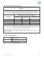
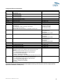
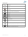
Innovative Pressure Mapping Solutions
FSA 4.0
Instructions for Use
Version 4, Rev 3 ©2012
English
Table of Contents
Table of Contents.................................................................................................................................................................. 2
FSA 4.0 Instructions for Use - Basic Setup and Operations.................................................................................................. 3
1. System Requirements....................................................................................................................................................... 3
1.1 Minimum:.................................................................................................................................................................... 3
1.2 Recommended: .......................................................................................................................................................... 3
1.3 For video: ................................................................................................................................................................... 3
2. Software ............................................................................................................................................................................ 3
2.1 Software Installation ................................................................................................................................................... 3
2.2 FSA Support Files installation .................................................................................................................................... 3
3. Hardware Setup ................................................................................................................................................................ 3
3.1 USB Connection Type 4, Type 5 and Type 5E Modules ............................................................................................ 3
3.2 Serial Connection Type 4 Modules Only .................................................................................................................... 4
4. Uploading Firmware .......................................................................................................................................................... 4
5. Installing the FSA USB Drivers ......................................................................................................................................... 4
6. Basic Software Operation.................................................................................................................................................. 4
7. Calibration Verification ...................................................................................................................................................... 5
8. Acceptable Calibration Values .......................................................................................................................................... 5
9. Accuracy ........................................................................................................................................................................... 5
10. Cautions .......................................................................................................................................................................... 5
10.1 Proper Care of FSA Mats ......................................................................................................................................... 5
10.2 Cleaning the FSA mat .............................................................................................................................................. 5
10.3 Proper Care of the Interface Modules ...................................................................................................................... 6
11. User Assistance Information ........................................................................................................................................... 7
12. Safety & Electronic Emissions Notices............................................................................................................................ 7
12.1 CAN/CSA C22.2 601.1-M90, UL 60601-1 and EN60601-1 ...................................................................................... 7
13. Product Environmental Specifications........................................................................................................................... 11
14. Approved Parts and Accessories .................................................................................................................................. 12
15. Definition of Symbols .................................................................................................................................................... 13
FSA4 Instructions for Use - ENGLISH A4 ver 4 rev 3.doc
2
FSA 4.0 Instructions for Use - Basic Setup and Operations
1. System Requirements
1.1 Minimum:
A PC running the Windows XP, Windows Vista or Windows 7 32 bit operating systems with current service
packs.
10 MB of free hard drive space.
128 MB RAM or minimum required for operating system in use, whichever is greater.
Display capable of High Color (16 bit), 800x600 resolution.
CD-ROM drive.
A USB port; 2 required if using a FSA AutoCalibrator or 2 or more Interface Modules at a time.
1.2 Recommended:
A PC running the Windows XP operating system
1 GB RAM or minimum required for operating system in use, whichever is greater.
Display set to 24 or 32 bit, with a 1024x768 resolution.
1.3 For video:
Camera must have VFW (Video For Windows) or WIA (Windows Image Acquisition) compatibility.
2. Software
2.1 Software Installation
1. Insert the ‘FSA Software CD’ into the CD-ROM drive (typically D :\) on your computer. If the setup does not
start automatically:
- Click the ‘Start’ button and choose ‘Run’ from the drop down menu that appears (or hit the Windows + R
keys together).
- Type ‘D: \setup’ in the dialog box that appears. Left mouse click on ‘OK’.
2. Follow the instructions in the installation wizard.
2.2 FSA Support Files installation
The "FSA Support Files" CD(s) must be installed after the FSA Software has been installed.
If you receive the "FSA Software CD" only, proceed to Hardware Setup. Your Sensor Array, Template files, etc.
will install with the software.
If you receive one or more 'FSA Support Files" CD's, repeat steps under Software Installation above, replacing
the ‘FSA Software CD’ with the ‘FSA Support Files’ CD.
3. Hardware Setup
3.1 USB Connection Type 4, Type 5 and Type 5E Modules
1. Types 4, 5 and 5E - locate the FSA USB Cable LI##62, Interface Module and Universal Power Supply
ACC####. A power supply is not required with a Type 5/5E Interface Module; it is powered by the computer
via the USB Cable.
2. Types 4, 5 and 5E - plug the FSA USB cable’s USB A (the rectangular end) securely into an available USB
port on your computer.
3. Type 4 Module only - plug the Interface Power Supply into the back of the interface module.
4. Types 4, 5 and 5E - plug the FSA USB cable’s USB B (the squared end) into the back of the interface
module. The green LED light will illuminate and blink on the face of the Type 5/5E Module, and you should
hear a Windows ‘Device Connect’ beep. You have completed connecting your Type 5/5E Interface Module.
If this is the first time you have connected this module to this USB port, the Windows 'Found New Hardware'
Wizard will appear in the status bar. Wait for the message 'Your device is ready to use' before proceeding to use
your FSA system.
The remaining instructions apply to the Type 4 Interface Module only:
5. Plug the Interface Power Supply into a power source.
If connected properly, the green light on the interface module will illuminate, indicating the interface module is
FSA4 Instructions for Use - ENGLISH A4 ver 4 rev 3.doc
3
receiving power. You should hear a Windows ‘Device Connect’ beep. If this is the first time you have
connected an FSA Type 4 module to this computer, the Windows 'Found New Hardware' Wizard will appear in
the status bar. Wait for the message 'Your device is ready to use' before proceeding to use your FSA system.
6. Find the FSA mat. Plug the mat’s ribbon cable securely into receptacle A of the interface module, if your
FSA mat has two connectors, connect to Port A and Port B as indicated on connector label. Use receptacle
B for a second FSA mat’s ribbon cable. Be sure to keep the connector straight when inserting and removing
so as not to bend the pins.
3.2 Serial Connection Type 4 Modules Only
1. Locate the 6’ Serial FSA Cable LI3, Interface Module, and the Interface Power Supply ACC####.
2. Plug the 6’ Serial FSA Cable into an available DB9 COM port on your computer.
3. Plug the Interface Power Supply into the back of the Interface Module.
4. Plug the 6’ Serial FSA Cable’s 8-wire plug end into the back of the Interface Module.
5. Plug the Interface Power Supply into a power source.
If connected properly, the green LED lights on the interface module will illuminate, indicating the interface module
is receiving power.
6. Refer to/same as step 6 under 'USB Connection Type 4 and Type 5/5E Interface Modules'.
NOTES: As of November 1st 2009, the LI3 6' FSA Serial Cable and LI5 6' Serial Extension Cable will no longer
be provided with your FSA system. They are available as optional accessories if required, please contact your
distributor.
The behavior of the LED lights on the interface modules changed for software version 4.0.227 and up. If you are
using FSA software prior to 4.0.227, you will need to install the current software and upload the current firmware
to your interface module in order to get the LED behavior outlined above, see Section 4 Uploading Firmware
below. If you install the current software and elect to not perform an Upload Firmware, your LED behavior will
remain as is; please refer to the user manual that shipped with your existing interface module.
4. Uploading Firmware
1. Install the current software as explained in section 2.
2. Connect your interface module to your computer as instructed in sections 3.1 or 3.2
3. Open the software, go to Tools-System Settings, Interface Module and click the Upload Firmware button.
The Upload Firmware Wizard will step you through uploading current firmware to your interface module so the
LED's behave as described in sections 3.1 or 3.2.
5. Installing the FSA USB Drivers
As of FSA software version 4.0.219 CD or internet download versions, the USB drivers for your FSA Type 4, 5
and 5E Interface Modules as well as the optional FSA Autocalibrator will install over the internet or when the
software is installed.
6. Basic Software Operation
1. Double click on the FSA4 icon on your desktop to run the program.
2. Go to File-New and select either your mat type from the Template tab, or your mat's serial number from the
Sensor arrays tab.
3. Click OK.
Your FSA Status bar should indicate ‘Ready to Read’, and a serial number should be displayed. If the serial
number indicated matches the serial number of the mat you have plugged into your interface module, you should
be ready to collect data. Go to step 4 below.
If your FSA Status Bar does not display a serial number, either:
i - Your Sensor Array files are not installed or not installed where they should be; please review section 2.2
FSA Support Files Installation.
ii - The template selected in step 1 above does not correspond to the style of mat you own. Please verify
what style of mat you own (example Seat, Bed).
4. Click the ‘Client Information’ tab to enter information that applies to this client/file as a whole.
5. Click on the Recording tab, the title on the tab is dependant on the Template selected in step 2.
6. Left mouse click either the ‘Scan’ or ‘Record’ buttons in the FSA4 Toolbar to start collecting data.
Scan collects data one frame at a time; click ‘Scan’ once to start scanning, click ‘Scan’ again to stop. The last
image will be kept. Repeat as required.
Record collects data continuously until you click Record again to stop.
FSA4 Instructions for Use - ENGLISH A4 ver 4 rev 3.doc
4
7. When the Scan or Record functions are disengaged, left mouse click in the ‘Note’ area at the
bottom of your FSA window to add frame specific notes, if required.
8. Go to File-Save to save your file.
7. Calibration Verification
Every FSA mat is calibrated to the appropriate working pressure range. Calibration information is stored within
the SensorArray file. We recommend following a monthly calibration schedule. Increase calibration frequency
when conducting research, when statistically analyzing pressure values, or when numerical pressure values are
critical.
8. Acceptable Calibration Values
(When performing validation on calibrations)
When viewing the verification file to validate the calibration, ensure the following criteria:
Coefficient of Variation
Acceptance Limit: The coefficient of variation must be less than 10%.
Verification levels: Assessment is made at the 50% level and one step below and one step above, for both
increase and decrease in pressure.
Range of Readings
Acceptance Limit: At a specific pressure level each sensor must not read higher or lower than an amount that is
10% of the maximum pressure
Verification Levels: Assessment is made at the 50% level and one step below and one step above, for both
increase and decrease in pressure.
The Calibration Wizard creates verification for you by default when you calibrate your mat, it will be stored in your
default FSA Documents directory, and the file name will be the serial number of your mat.
9. Accuracy
FSA pressure mapping sensors are accurate to within +/- 20% over the recommended operating range.
For more details please refer to sections 7 - Calibration Verification and 8 - Acceptable Calibration Values.
10. Cautions
10.1 Proper Care of FSA Mats
- Do not fold the mat.
- Keep the mat dry. Protect the mat from incontinence, torque and shear forces by using the isolation bags
provided.
- Place the mat gently on surfaces by using the corners.
- Do not pull on or carry the mat by the ribbon cable.
- Do not pivot on the mat.
- Do not pull on the edges of the mat while it is under a client.
- Do not pinch the mat between moving components of a support surface.
- Store the mat flat or in the original packaging (roll the mat around the foam core and store in the shipping
tube).
The Nylon or Nylon/Lycra covering should not be put in direct contact with broken skin. Improper care of and /or
use of FSA mat(s) could possibly lead to malfunction, failure or damage to the FSA pressure-sensing mat.
10.2 Cleaning the FSA mat
FSA mats are typically covered in Polyurethane coated ripstop Nylon, 10 mil Polyurethane or Polyurethane coated
Nylon/Lycra stretch fabric. We recommend you use the isolation bags provided with your system at all times to protect
against incontinence as well as torque and shear forces. The following applies to any of our listed, typical coverings:
-
For daily cleaning, we recommend wiping down with a damp, not wet cloth using a mild soap and water
solution.
Mild alcohol based cleaners and cleaners containing no more than 10% bleach in non-wetting amounts may
also be used.
Other cleaners/ disinfectants sold under the following names may also be used: Viraguard, Cavicide, Vitre
Tb, SeptFx.
FSA4 Instructions for Use - ENGLISH A4 ver 4 rev 3.doc
5
-
Undiluted bleach and Hydrogen Peroxide are not recommended.
Cleaning products or disinfectants must be thoroughly wiped off after use. Allow mat to dry thoroughly before
use or storage.
Isolation bags are intended for single use only; dispose of them according to your institution's biological waste
disposal guidelines.
10.3 Proper Care of the Interface Modules
- Do not drop the interface modules.
- There are no user serviceable parts in the interface modules, do not open them.
- Protect the interface modules from exposure to moisture.
- Store the interface modules in a location where it is protected from falling or in the original packaging
(inside of the foam core and store in the shipping tube).
- The Type 4 Interface Module operates on 9V AC or battery power. To protect against possible damage
to the interface module, only use the power supply provided with the system, refer to safety notices
indicated below.
- Disconnect the battery pack from the module if not in use for an extended period.
- The Type 5 and 5E Interface Modules operates on power supplied by the computer via the #LI62
ferrited USB cable provided with the system. Use only the USB cable provided with your Type 5/5E
Interface Module.
- Do not remove the ferrites on the LI61USB cable (2) or the sensing mat cable (1) supplied with your
Type 5/5E Interface Module and mat.
- If module function stops during use, reset the module by disconnecting then reconnecting the power
source from the device.
- We recommend the use of a suitable surge protector with the FSA interface module, as would be
appropriate with any computer and/or computer peripheral.
- Type 4 Interface Module only - plug the mat’s ribbon cable securely into the interface module, be sure to
keep the connector straight when inserting and removing so as not to bend the pins.
- It is the operator's responsibility to ensure all cables are in good condition; inspect all cables for nicks or
abrasions prior to each use.
- To clean, disconnect the module from the power supply. Wipe the exterior of the interface module with a
soft cloth dampened with water. Do not use liquid or aerosol cleaners which may contain flammable
substances.
Also see Safety Notices: CAN/CSA C22.2 601.1-M90, UL 60601-1 and EN60601-1, Electronic Emissions Notices
below
Improper care and /or use of the FSA Interface Module could possibly lead to malfunction, failure or damage to
the FSA Interface Module.
If function stops during electrostatic discharge to the device, reset the system by unplugging from the PC,
rebooting the PC and plugging in the module.
FSA4 Instructions for Use - ENGLISH A4 ver 4 rev 3.doc
6
11. User Assistance Information
If you have any questions about the FSA System, or if you are experiencing technical difficulties, please contact
Vista Medical Ltd. at the following address:
Vista Medical Ltd.
Unit 3-55 Henlow Bay
Winnipeg, Manitoba, Canada R3Y 1G4
Phone: 1-204-949-7661 North America Toll Free Technical Support 800-847-3157
E-mail: [email protected], web: www.pressuremapping.com
Outside of North America:
Please contact your distributor. A listing of our worldwide distributors can be found online at
www.pressuremapping.com, look for the Contact link.
EC Representative (regulatory affairs only):
Emergo Europe
Molenstraat 15
2513 BH, The Hague
The Netherlands
Phone: +31.70.345.8570
Fax: +31.70.346.7299
12. Safety & Electronic Emissions Notices
12.1 CAN/CSA C22.2 601.1-M90, UL 60601-1 and EN60601-1
This product has been tested and found to comply with CAN/CSA C22.2 601.1-M90, UL 60601-1 and EN606011. The following information is provided for clarification:
- Medical Device Type: Class I with measurement function
- Degree of protection against electric shock: Type B Applied Part
- Degree of protection against ingress of water: IPX0
- Degree of safety of application in the presence of a flammable anaesthetic mixture with air or with
oxygen or nitrous oxide: Equipment not suitable for use in the presence of a flammable anaesthetic
mixture with air or with oxygen or nitrous oxide.
- Mode of operation: Continuous
- Environmental Operating Conditions: 10-40°C, 30-75% rH non-condensing, 700-1060hPa
12.2 Federal Communications Commission (FCC) statement
The Federal Communications Commission (in 47 CFR 15.105) has specified that the following notice be brought
to the attention of the users of this product.
This equipment has been tested and found to comply with the limits for a Class A digital device, pursuant to Part
15 of the FCC Rules. These limits are designed to provide reasonable protection against harmful interference
when the equipment is operated in a commercial environment. This equipment generates, uses, and can radiate
radio frequency energy and, if not installed and used in accordance with the instruction manual, may cause
harmful interference to radio communications. Operation of this equipment in a residential area is likely to cause
harmful interference in which case the user will be required to correct the interference at his own expense. The
end user of this product should be aware that any changes or modifications made to this equipment without the
approval of Vista Medical could result in the product not meeting the Class A limits, in which case the FCC could
void the user's authority to operate the equipment.
This device complies with Part 15 of the FCC Rules. Operation is subject to the following two conditions: (1) this
device may not cause harmful interference, and (2) this device must accept any interference received, including
interference that may cause undesired operation.
12.3 Industry Canada compliance statement
This Class A digital apparatus complies with Canadian ICES-003.
Cet appareil numérique de la classe A est conforme a la norme NMB-003 du Canada
FSA4 Instructions for Use - ENGLISH A4 ver 4 rev 3.doc
7
12.4 IEC 60601-1-2:2004 (Ed 2.1)
This product has been tested and found to comply to IEC 60601-1-2:2004 (Ed 2.1) for electromagnetic
compatibility (EMC) as a Class A product. The tests performed and test levels are listed in the accompanying
tables. The user, operator or installer of this equipment is advised of the following:
1.
2.
3.
In a domestic environment this product may cause radio interference in which case the user may be
required to take adequate corrective measures.
Portable and mobile RF communications can affect medical electrical equipment.
This equipment/system is intended for use by healthcare professionals only. This
equipment/system may cause radio interference or may disrupt the operation of nearby
equipment. It may be necessary to take mitigation measures such as:
Reorienting or relocating the receiving antenna.
Increasing the separation between the equipment and the receiver.
Connecting the equipment into an outlet on a circuit different from that to which the receiver is
connected.
Consult the dealer or an experienced radio/TV technician for help.
4 WARNING: Use of this equipment with accessories or cables other than those qualified and sold by Vista
Medical may result in increased emissions or decreased immunity of this equipment and may cause the
system to be non-compliant with the requirements of IEC 60601-1-2:2004 (Ed 2.1).
5. This equipment should not be stacked or used adjacent to other equipment. If stacked or adjacent use is
necessary, the equipment should be observed to verify normal operation in the configuration in which it is
used.
6. External equipment, i.e. personal computer, intended for connection to signal input, signal output or other
connectors, shall comply with relevant EN standard (e.g. EN 60950 for IT equipment and the EN 60601
series for Medical electrical equipment). In addition, all such combinations, medical equipment intended to
be connected to the other equipment – systems - shall comply with the standard EN 60601-1-1, Safety
requirements for medical electrical systems.
Equipment not complying with EN 60601 shall be kept outside the patient environment, as defined in the
standard. ¹
Any person who connects external equipment to signal input, signal output or other connectors has formed a
system and is therefore responsible for the system to comply with the requirements of EN 60601-1-1. If in
doubt, contact qualified technician or your local representative.
¹ The normal distance of at least 1.5 m from the patient or the patient support shall be provided.
The FSA product has been certified to comply with 93/42/EEC for the purposes of CE Marking as a Medical
Device.
FSA4 Instructions for Use - ENGLISH A4 ver 4 rev 3.doc
8
IEC 60601-1-2:2004 (Ed 2.1) Table 201 Requirements
The equipment is intended for use in the electromagnetic environment specified below. The customer or the
user of the equipment should assure that it is used in such an environment.
Emissions test
Compliance
RF emissions CISPR 11
Group 1
RF emissions
CISPR 11
Class A
Harmonic emissions IEC
61000-3-2
Class A
Voltage fluctuations/ flicker
emissions
IEC 61000-3-3
Complies
Electromagnetic environment – guidance
The equipment uses RF energy only for its internal function. Therefore, its
RF emissions are very low and are not likely to cause any interference in
nearby electronic equipment.
The equipment is suitable for use in all establishments other than domestic,
and may be used in domestic establishments and those directly connected
to the public low-voltage power supply network that supplies buildings used
for domestic purposes, provided the following warning is heeded: Warning:
This equipment/system is intended for use by healthcare professionals
only. This equipment/ system may cause radio interference or may disrupt
the operation of nearby equipment. It may be necessary to take mitigation
measures, such as re-orienting or relocating the equipment or shielding the
location.
IEC 60601-1-2:2004 (Ed 2.1) Table 202 Requirements
The equipment is intended for use in the electromagnetic environment specified below. The customer or the
user of the Equipment should assure that it is used in such an environment.
Immunity test
IEC 60601 test level
Compliance level
Electromagnetic environment – guidance
Electrostatic discharge
(ESD) IEC 61000-4-2
±6 kV contact ±8 kV air
±6 kV contact ±8 kV air
with documented
necessary
Floors should be wood, concrete or ceramic tile. If
floors are covered with synthetic material, the
relative humidity should be at least 30 %.
Electrical fast
transient/burst IEC
61000-4-4
±2 kV for power supply
lines ±1 kV for
input/output lines
±2 kV for power supply
lines ±1 kV for
input/output lines
Mains power quality should be that of a typical
commercial or hospital environment.
Surge IEC 61000-4-5
±1 kV line(s) to line(s)
±2 kV line(s) to earth
±1 kV line(s) to line(s)
±2 kV line(s) to earth
Mains power quality should be that of a typical
commercial or hospital environment.
<5 % UT (>95 % dip in
UT) for 0,5 cycle 40 %
UT (60 % dip in UT) for 5
cycles 70 % UT (30 %
dip in UT) for 25 cycles
<5 % UT (>95 % dip in
UT) for 0,5 cycle 40 %
UT (60 % dip in UT) for 5
cycles 70 % UT (30 %
dip in UT) for 25 cycles
No anomalies
Voltage dips, short
interruptions and
voltage variations on
power supply input
lines IEC 61000-4-11
UT = 230 Vac
<5 % UT (>95 % dip in
UT) for 5 sec
Power frequency (50
Hz) magnetic field IEC
61000-4-8
FSA4 Instructions for Use - ENGLISH A4 ver 4 rev 3.doc
3 A/m
95% dip meets
requirements.
3 A/m
Mains power quality should be that of a typical
commercial or hospital environment. If the user of
the equipment requires continued operation
during power mains interruptions, it is
recommended that the equipment be powered
from an uninterruptible power supply or a battery.
Power frequency magnetic fields should be at
levels characteristic of a typical location in a
typical commercial or hospital environment.
9
IEC 60601-1-2:2004 (Ed 2.1) Table 204 Requirements
The equipment is intended for use in the electromagnetic environment specified below. The customer or the
user of the equipment should assure that it is used in such an environment.
Immunity test
IEC 60601 test level
Conducted RF
IEC 61000-4-6
3 Vrms
150 kHz to 80 MHz
Compliance
level
1 Vrmsa
Electromagnetic environment – guidance
Portable and mobile RF communications equipment should be
used no closer to any part of the equipment including cables,
than the recommended separation distance calculated from the
equation applicable to the frequency of the transmitter.
Recommended separation distance
Radiated RF IEC
61000-4-3
3 V/m 80 MHz to 2,5
GHz
3 V/m
where P is the maximum output power rating of the transmitter
in watts (W) according to the transmitter manufacturer and d is
the recommended separation distance in meters (m). Field
strengths from fixed RF transmitters, as determined by an
electromagnetic site surveya should be less than the
compliance level in each frequency rangeb
Interference may occur in the vicinity of known RF transmitting
devices and equipment marked with the following symbol:
NOTE 1 At 80 MHz and 800 MHz, the higher frequency range applies.
NOTE 2 These guidelines may not apply in all situations. Electromagnetic propagation is affected by absorption and reflection from
structures, objects and people.
a) Field strengths from fixed transmitters, such as base stations for radio (cellular/cordless) telephones and land mobile radios,
amateur radio, AM and FM radio broadcast and TV broadcast cannot be predicted theoretically with accuracy. To assess the
electromagnetic environment due to fixed RF transmitters, an electromagnetic site survey should be considered. If the measured
field strength in the location in which the equipment is used exceeds the applicable RF compliance level above, the equipment
should be observed to verify normal operation. If abnormal performance is observed, additional measures may be necessary, such
as re-orienting or relocating the equipment
b) Over the frequency range 150 kHz to 80 MHz, field strengths should be less than 1 V/m.
FSA4 Instructions for Use - ENGLISH A4 ver 4 rev 3.doc
10
IEC 60601-1-2:2004 (Ed 2.1) Table 206 Requirements
Recommended separation distances between portable and mobile RF communications equipment and the
EQUIPMENT
The EQUIPMENT is intended for use in an electromagnetic environment in which radiated RF disturbances are controlled. The
customer or the user of the EQUIPMENT can help prevent electromagnetic interference by maintaining a minimum distance
between portable and mobile RF communications equipment (transmitters) and the EQUIPMENT as recommended below,
according to the maximum output power of the communications equipment.
Separation distance according to frequency of transmitter m
Rated maximum output power of
transmitter W
150 kHz to 80 MHz
D = 3.5 √ P
80 MHz to 800 MHz
D = 1.2 √ P
800 MHz to 2.5 GHz
D = 2.3 √ P
0.01
0.35
0.12
0.23
0.1
1.1
0.38
0.73
1
3.5
1.2
2.3
10
11
3.8
7.3
100
35
12
23
For transmitters rated at a maximum output power not listed above, the recommended separation distance d in metres (m) can be
estimated using the equation applicable to the frequency of the transmitter, where P is the maximum output power rating of the
transmitter in watts (W) according to the transmitter manufacturer.
NOTE 1 At 80 MHz and 800 MHz, the separation distance for the higher frequency range applies.
NOTE 2 These guidelines may not apply in all situations. Electromagnetic propagation is affected by absorption and reflection from
structures, objects and people.
13. Product Environmental Specifications
Temperature:
Relative Humidity:
Atmospheric pressure:
Operating: 10 to 40°C
Storage: -40 to +70°C
Operating: 30 to 75% RH (non-condensing)
Storage: 10 to 100% RH (non-condensing)
Operating: 700 to 1060 hPa
Storage: 500 to 1060 hPa
FSA4 Instructions for Use - ENGLISH A4 ver 4 rev 3.doc
11
14. Approved Parts and Accessories
Part#
Description
LI2
FSA1050
Interface Module Type 4
9V DC 500 mA
Interface Module Type 5
5V DC 250 mA (via USB)
Interface Module Type 5E
5V DC 250 mA (via USB)
Interface Module Wireless Type 5
Interface Module Wireless Type 5E
European (Schuko) Cord Set, 8'/2.5m
UK Cord Set, 8'/2.5m
North American Cord Set, Medical Grade, 10'/3m
Danish Cord Set, Medical Grade, 8'/2.5m
Interface Power Supply, 9V Universal Medical Grade Power Supply
Model# WM10-9V
Input: 100-240VAC, 50-60Hz, 0.4A/Output: 9VDC/1000mA
Output Connector: 5.5x2.1x12mm
Approvals: CSA 22.2 No. 601, UL60601, TUV EN60601, CE Mark (LVD)
Battery Pack 9V
FSA1055
Wireless Type 5 Battery Pack (open)
FSA1056
Wireless Type 5 Battery Pack (closed)
FSA1060
LI3
LI5
LI8
LI62
ACC018/ACC024
9V Battery
LI20
LI25
LI24
LI26
ACC2010
ACC3010
ACC3015
ACC8015
ACC2021
ACC9011
Other
Max. length 10'/3m
Max. length 10'/3m
Max. length 10'/3m
Max. length 10'/3m
Manufactured by:
1 - PowDec Technologies
7013 Realm Drive Suite E
San Jose CA 95119 USA
Manufactured by:
Priority Electronics Ltd.
55 Trottier Bay
Winnipeg MB Canada R3T 3R3
Manufactured by:
Priority Electronics Ltd.
55 Trottier Bay
Winnipeg MB Canada R3T 3R3
Manufactured by:
Priority Electronics Ltd.
55 Trottier Bay
Winnipeg MB Canada R3T 3R3
Max. length 10'/3m
6'/1.8m FSA Serial Cable type 4
6'/1.8m Serial Extension Cable
Max. length 10'/3m
4'/1.2m InShoe/Custom Extension Cable, black
Max. length 10'/3m
6'/1.8m USB Cable (with ferrites)
Max. length 10'/3m
Type 5/5E Wireless Kit:
1 - LI24 Interface Module Type 5 (Wireless)/LI26 Interface Module Type 5E
(Wireless)
1 - LI141 SD1000 Bluetooth Serial Adaptor with 1 dBi stub antenna
1 - LI142 UD100 Bluetooth USB Adaptor with 1 dBi stub antenna
1 - L13C - 9"/23cm Parani Cable (Type 5)
1 - FSA1056 - 9V Battery Pack and Battery
1 - Instructions Also includes 1 - LI62 1.8m/6' USB Cable (with ferrites) for wired use
Type 4 Wireless Kit:
1 - LI141 SD1000 Bluetooth Serial Adaptor with 1 dBi stub antenna
1 - LI142 UD100 Bluetooth USB Adaptor with 1 dBi stub antenna
1 - LI121 - 12"/30cm Parani Cable (Type 4)
1 - FSA1056 - 9V Battery Pack and Battery
1 - Instructions
WARNING: Use of this equipment with accessories or cables other than those qualified and sold by Vista Medical may result
in increased emissions or decreased immunity of this equipment and may cause the system to be non-compliant with the
requirements of IEC 60601-1-2:2004 (Ed 2.1).
FSA4 Instructions for Use - ENGLISH A4 ver 4 rev 3.doc
12
15. Definition of Symbols
Alternating current
Direct current
Type B applied part
Caution risk of danger or attention, consult accompanying document
Manufactured by
Serial number
Model number
EC representative
Electrostatic sensitive device
Keep dry
Do not dispose of with other waste products; contact your distributor or the manufacturer for instructions.
Type 4 Module - Start or Stop recording mode
Type 5/5E Module - User input required as instructed in manual.
FSA4 Instructions for Use - ENGLISH A4 ver 4 rev 3.doc
13