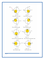
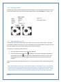
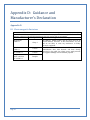
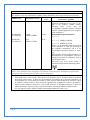
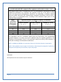
1
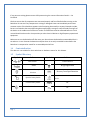
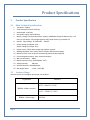
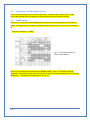
RosieScan™ Bladder Scanner By Nurse Rosie Products, distribute by Life Systems Inc. Page 1 Forward Nurse Rosie Products, distributed by Life Systems, Inc. would like to thank you for your purchase of the RosieScan™ Bladder Scanner. Please read this manual carefully before using the RosieScan. Familiarize yourself with the features, methods of use, cautions and warnings, as well as any limitations of the scanner. This manual should be kept in a safe, convenient place for future reference. No part of this manual should be reprinted or reproduced without written consent from Life Systems Inc., distributed by Life Systems Inc., maintains the right to modify the contents of this manual without prior notice. If you have any questions about the information presented in this manual or about other Nurse Rosie Products, distributed by Life Systems Inc., please contact us at: Nurse Rosie Products / Life Systems Inc. 7320 Central Avenue Savannah, Georgia 31406 www.nurserosie.com 800-841-1109 Page 2 Table of Contents 1. 2. Table of Contents Introduction .......................................................................................................................................... 6 1.1 General Description ...................................................................................................................... 6 1.2 Primary Components .................................................................................................................... 6 1.3 Intended Use ................................................................................................................................. 6 1.4 Contraindication ........................................................................................................................... 7 1.5 Symbol Directory........................................................................................................................... 7 Product Specification ............................................................................................................................ 8 2.1 Main Technical Specifications ....................................................................................................... 8 2.2 Accuracy Range ............................................................................................................................. 8 2.3 Instructions for Environment Test ................................................................................................ 9 2.4 Sound Output ................................................................................................................................ 9 3. System Overview.................................................................................................................................... 10 3.1 Primary Components .................................................................................................................. 10 3.1.1 Hardware Components ....................................................................................................... 10 3.1.2 Embedded Software System ............................................................................................... 10 3.2 Pictures and Descriptions ........................................................................................................... 11 3.3 Circuit Diagram and Part List ...................................................................................................... 13 4. Control Panel....................................................................................................................................... 14 5. Optimal Conditions ............................................................................................................................. 15 5.1 For Use .............................................................................................................................................. 15 5.2 For Storage ........................................................................................................................................ 15 5.3 For Transportation ............................................................................................................................ 15 6. Installation .......................................................................................................................................... 16 6.1 7. Installation Instructions .............................................................................................................. 16 Navigation ........................................................................................................................................... 18 7.1 Page 3 Before Powering Up .................................................................................................................... 18 7.2 Powering On................................................................................................................................ 18 7.3 Ready Screen............................................................................................................................... 19 7.4 System Reset Screen ................................................................................................................... 21 7.4.1 Time .................................................................................................................................... 21 7.4.2 Date ..................................................................................................................................... 22 7.4.3 Print Images ........................................................................................................................ 22 7.4.4 Image Display: ..................................................................................................................... 22 7.4.5 Hospital ............................................................................................................................... 23 7.4.6 Alarm ................................................................................................................................... 23 7.4.7 Sound .................................................................................................................................. 23 7.4.8 Volume Calibration ............................................................................................................. 24 7.5 The Scan Screen .......................................................................................................................... 26 7.6 The Scan Results Screen.............................................................................................................. 28 7.7 Gray Scale Results Screen ........................................................................................................... 29 7.8 The Save/Edit Screen .................................................................................................................. 30 7.9 Browsing Historical Records........................................................................................................ 31 7.9.1 Deleting Stored Records ..................................................................................................... 32 7.9.2 Location Presentation ......................................................................................................... 32 7.10 Printing Results ........................................................................................................................... 34 7.11 Exporting Data to a PC ................................................................................................................ 34 7.12 Recharging the Battery ............................................................................................................... 35 8. Clinical Application .............................................................................................................................. 37 8.1 Instructions for Use in a Clinical Setting ..................................................................................... 37 8.2 Images of Invalid Scan Results .................................................................................................... 38 9. Transportation and Storage ................................................................................................................ 40 9.1 Transportation ............................................................................................................................ 40 9.2 Storage ........................................................................................................................................ 40 10. Maintenance and Service................................................................................................................ 41 10.1 Maintenance for Probe ............................................................................................................... 41 10.2 Main Unit Maintenance .............................................................................................................. 41 Page 4 10.3 Service Guide .............................................................................................................................. 41 11. Troubleshooting .............................................................................................................................. 43 12. Quick Reference Guide ................................................................................................................... 44 Appendix A .................................................................................................................................................. 45 Appendix B .................................................................................................................................................. 48 B.1 Warnings ..................................................................................................................................... 48 B.2 Recharging and Discharging ........................................................................................................ 48 B.3 Storage ........................................................................................................................................ 49 B.4 Transportation ............................................................................................................................ 49 B.5 Other Instructions ....................................................................................................................... 49 Appendix C .................................................................................................................................................. 50 C.1 Pre-Scan Image to the Left of Center.......................................................................................... 50 C.2 Pre-Scan Image to the Right of Center ....................................................................................... 51 Appendix D .................................................................................................................................................. 53 D.1 Electromagnetic Emissions .............................................................................................................. 53 D.2 Page 5 Electromagnetic Immunity.......................................................................................................... 54 1. Introduction 1.1 General Description Introduction The RosieScan (“Device”) is a noninvasive ultrasound device used to measure urinary bladder volume. During each scan, the RosieScan creates a three-dimensional image of the bladder. This image is then used to automatically calculate and display the urinary bladder volume. The results of the scan may be stored internally, printed using the on-board thermal printer or transferred to an external computer using a USB connection. The RosieScan can be programmed to make calculations based on a male, female or pediatric bladder before each scan. The RosieScan can store up to 100 patient I.D.s and measurements. When the memory is full the results may be transferred to an external computer and the on board memory can be cleared. 1.2 Primary Components The RosieScan consists of a Main Unit, Probe (standard frequency 2.6MHz), two Batteries, a USB cable, Adapter and Charger. 1.3 Intended Use The device is intended to provide a noninvasive means of measuring urinary bladder volume by a licensed medical professional. All users must read this entire manual prior to using the RosieScan. Failure to comply with these instructions may compromise the performance of the device and the accuracy of its measurements. Immediately after unpacking your new RosieScan, refer to the parts list below to ensure that all parts are included in your package. Also verify that the user’s manual, maintenance document and all accessories are included. No. 1 2 3 4 5 6 7 8 Page 6 RosieScan Packing List Name of Parts Main Unit Probe Adapter Charger Battery USB Cable Cross Screwdriver Certificate Quantity 1 1 1 1 2 1 1 1 If any parts are missing please contact Life Systems using the contact information listed in the Foreword. Check to ensure that all components are connected properly and free of defect before turning on the RosieScan. Do not use if any component is missing or damaged. Cease use immediately and contact customer service if the RosieScan appears to be functioning abnormally in any way. Examples include, but are not limited to the screen becoming abnormally bright, strange or unusual sounds coming from the device or the sudden smell of fumes or smoke. The RosieScan must be calibrated before its initial use and should not be used in close proximity to other electrical devices or high-frequency operational equipment. Make sure to turn the RosieScan off after every use. Do not leave the RosieScan unattended while it is turned on or in use. Remove the batteries and place them in an easily accessible location before the RosieScan is transported or stored for an extended period of time. 1.4 Contraindication The device is not suitable for those who have an abdomen wound or skin disease. 1.5 Symbol Directory Symbol Indicates Symbol Indicates USB screen Class II device Probe Indicate arrow of battery insert direction Open the battery buckle Lock the battery buckle Switch indicator Page 7 B-type application Be away from liquid intrusion Check the documents enclosed in the device DC AC 2. Product Specification 2.1 Main Technical Specifications 1 2 3 4 5 6 7 8 9 10 11 12 13 14 15 16 2.2 Product Specifications Transducer: 2.6MHz Probe: Mechanical Sector Scanning Detect depth : ≥140 mm; Host power supply: internal battery Battery: Voltage 7.4V (standard value), capacity: ≥4200mAh Charge the batteries for 3.5-4 hours for full charge. Fully charged batteries will provide 4 hours of sustained use Charger : Input voltage : AC 220V±10%,50±1HZ; Output voltage for adapter: 9.0V; Output voltage for charger: 8.5V; Output screen: USB for data storage and software upgrade Readings displayed: scan results, present location and ultrasound image Measured result: scan results are automatically measured and displayed. Case management options: Store, browse and export Max. measurement: 999ml; Measurement accuracy: 0ml≤V≤999ml, ±15%; Storage capacity: 100 cases Device dimensions: 310x260x50mm; Net weight: about 2.1 KG。(4.62 LBS) Accuracy Range Accurate results are contingent upon proper use of device. Explanation Narrative ±25%(60ml≦V≦150) Bladder volume accuracy ±15%(150ml≦V≦999) Bladder volume range Page 8 0-999ml 2.3 Instructions for Environment Test The environmental testing for the device should be in accordance with requirements of GB/T 14710-2009 (Medical electrical equipment environmental requirement and test method) 2.4 Sound Output The device is in accordance with GB16846-2008 and the announcement exemption for the public in chapter 6 of Requirement of medical ultrasound diagnosis device for its sound output (see Figure 21). Transducer frequency: 2.6MHz Fig 2-1 Technical Datasheet for Level of Sound Output Device is in accordance with requirements of GB9706.9-2008 -< Part 2-37 in Medical electrical equipment : 51.2aa),dd) in requirements for particular safety of ultrasound diagnostic and monitoring equipment> . Exempted from showing MI, TI. MI <1 TI<1 Page 9 3. System Overview 3.1 Primary Components System Overview The system consists of two parts --hardware circuit and embedded software. 3.1.1 Hardware Components The hardware circuit consists of an embedded micro-controller system, B-mode transducer, Bmode signal processing module, B-mode signal A/D conversion module, Step-motor driving module, LED display system, print system, keyboard input, high speed USB screen and the power/battery management system. Its composition is shown in Figure. 3-1: Figure 3-1 Hardware Configuration 3.1.2 Embedded Software System The embedded software system is fully designed according to the hardware structure to allow for better stability, ease of use and a friendly user screen. The software modules include B-mode ultrasonic-image data acquisition, image edge identification, step-motor drive control, LED drive, graphical menu display, printing, power management and USB data communication. Its components are shown in Figure 3-2. Page 10 Figure3-2 Software Module Block Diagram 3.2 Pictures and Descriptions The RosieScan consists of a main unit, ultrasonic probe and external thermal printer. 1. RosieScan see Figure 3-3 Figure 3-3 Device 1. LED Display 2. Control Panel 3. Printer 4. Power Light 5. Probe 6. Screen Buckle 7. Printer Cover 6 1 2 7 3 4 Page 11 5 2. Probe and USB Port see Figure 3-4 Figure 3-4 Ports 1. Probe Port 2. USB Port 2 1 3. 3D Probe see Figure 3-5 Figure 3-5 Ports 1. Probe Cable 2. USB Plug 3. Probe Perspective Window 1 3 Page 12 2 4. Battery Box see Figure 3-6 Figure 3-6 Battery Box 1. Battery 1 3.3 Circuit Diagram and Part List Please contact Life Systems Inc. for circuit diagram, parts list and any other information pertaining to maintenance or repairs. THE USER SHOULD NOT DISASSEMBLE OR TRY TO REPAIR THIS DEVICE. Page 13 4. Control Panel Control Panel Figure 4-1 Control Panel Page 14 5. Optimal Conditions 5.1 For Use Optimal Conditions Temperature range: +41~+105 F; Relative humidity: ≤70%; Atmospheric pressure: 700~1060 hPa; Power supply of charger: AC 220V±10%,50Hz±1Hz; Keep device away from strong electrical fields, strong magnetic fields and high-voltage equipment. 6. Use the socket from an independent power supply. 7. Images on the display may appear faded if viewed in bright rooms. The device should be used in rooms that are clean, and pollution free. Loud noises may result in inaccurate readings. 1. 2. 3. 4. 5. 5.2 For Storage 1. Temperature range: 23F~104F, 2. Relative humidity ≤ 80% 3. Scope of atmospheric pressure: 700 hPa~1060 hPa 5.3 For Transportation 1. Temperature range:. 14 F~131 F 2. Relative humidity ≤ 80% 3. Scope of atmosphere pressure: 700 hPa~1060 hPa Note: The battery should be removed before the device is transported. Page 15 6. Installation 6.1 Installation Instructions Installation 1. Put the device on a soft, flat surface. 2. Turn the main unit over so the bottom is facing up 3. To ensure that the battery is being installed correctly, confirm that the arrow corresponds with the arrow on the unit on the battery. 4. Slide the battery lock into the unlocked position and hold. See Figure 6-1 Figure 6-1 1. Batter Lock 1 5. Insert the battery into the battery slot while holding the battery lock in the unlocked position. 6. Then slide the battery lock into the locked position. 7. When the battery is successfully installed it will resemble Figure 6-2. The arrow on the battery is pointing directly at the arrow on the main unit. Page 16 Figure 6-2 Back view of main unit with battery in place Note: The device must be switched off before removing the battery. 8. To remove the battery, put the device on a soft, flat surface. Move the battery lock to the unlocked position, and then slowly pull the battery out of the unit. 9. To install the probe, find the red dots on the main unit port and on the plug at the end of the probe cord. See Figure 6-3. Align the two red dots and then plug the probe into the main unit. See Figure 6-4. Figure 6-3 Probe Installation Figure 6-4 Probe Installed Note: Do not scratch the surface of the probe. This will result in inaccurate readings. Only the probe supplied by the original manufacturer may be used with this device. Please contact Life Systems, Inc. in the event a replacement probe is needed. Page 17 Navigation 7. Navigation 7.1 Before Powering Up 1. Confirm that that battery is properly installed and locked 2. Confirm that the probe is properly installed 3. Confirm that the device is tightly secured on the stand (if applicable). 7.2 Powering On To turn on the device, press the “POWER” key. Once turned on, the device will automatically check t h e battery level, printer, probe connection, memory capacity and screen. The screen show in Figure 7-1 will display after the device is turn on Figure 7-1 Power On Screen Note: Once the device self-checks successfully, the system will enter its main system screen. If any of the items fails during self-checking, an alarm will alert you. If the alarm sounds, press direction key before entering the main system. If the printer fails, it will not influence your measurements Self-check displays: Battery Checking.…..OK Probe Checking……..OK Printer Checking…….OK Storage…………………..100% This means your battery is good and connected properly. This means the probe is connected correctly and ready to use. This means the printer is ready to print. Percent represents the remaining storage space. Note: If “Disconnect” is displayed instead of “OK” next to the probe-checking, remove and reconnect the probe. If “Disconnect” is still displayed, check the probe cord and contact Life Systems, Inc. Page 18 At the bottom right corner of the power on screen there will be two functional keys: The functional key displays when self-checking fails, so touch the directional key . key or press the on the control panel to enter “Ready” screen of system. You may touch stylist pen or press Power button with on the control panel to turn off the device. Note: The system will automatically power down if you do not press within 20 seconds of a self-check failure. 7.3 and key on the control panel Ready Screen Once RosieScan is finished self- checking the Ready screen will display on the monitor, see Figure 7-2. 1 2 3 Page 19 Figure 7-2 Ready Screen 1. Status Bar 2. Scan Mode 3. Touch Screen Navigation Keys On the top of the Ready screen you will see a Status bar. The icons below may change depending on the device’s self-check results. Please consult the Figure 7-3 for the meaning of each icon. Please contact Life Systems Inc. if you have any questions. Icon USB Probe Printer Prompt Alarm Battery Normal or successful connection Problem or no connection Figure 7-3 Status Bar and Instructions You will find two sets of navigation keys – one set on the Ready screen and one set on the control panel. See Figure 7-4 and 7-5. Figure 7-4 and 7-5 Navigation Keys Figure 7-4 Ready Screen Figure 7-5 Control Panel • Press key on the right or touch on the Ready screen to delete the max tested volume without switching off the device; • Press key on the left or touch • Press key or touch to to browse previously saved readings to select gender. Select the icon for male, the for female and the icon for Pediatric. Pediatric mode is only effective to measure volumes that are less than 100 ml. Page 20 • Press key or touch to enter the system reset screen. You can touch the screen to select features you need to change or use the directional keys on the control panel. For example touch ”Scan Images” to choose between scanning 12 or 24 images. You must click on Save/Exit in order to save your changes and go to the pre-scan screen. • Press key before entering the pre-scan screen. If the probe is not connected, the device will not enter the pre-scan screen. Note: Check to see if any icons on the status bar have changed. If they have, refer to Figure 7-3 on page 20. If you have any questions, please contact Life Systems Inc. 7.4 System Reset Screen Press the key or touch to enter the system reset screen (Figure 7-6) from the Ready screen. There the user can set the time, date, print mode, and display mode, name of facility, key prompt sounds and alarm on/off in the system. Press alarm on the screen for turning on/off alarm and sounds. Figure 7-6 System Reset Screen 7.4.1 Time Note: Time should be entered in the following format: Hour\Minute\Seconds 1. Press the ▲/▼ keys to move and select “Time” or use your stylist to select it on the screen (its background will turn purple). Page 21 key to underling HH and then press the ◄/► keys to move the underscore 2. Press the between HH/MM/SS (Hour/Minute/Seconds). Press the ▲/▼keys to adjust the time where the underscore is located. You can also use your stylist to touch HH, MM, or SS to change the time. A n u n d e r s c o r e w i l l a p p e a r u n d e r t h e n u m b e r y o u w i s h t o c h a n g e . Tap the desired number (0-9) with the stylist pen. The underscore will then automatically move to the next option until you complete your setting. 3. Press the OK key to confirm the setting or touch “Time” with stylist pen again to save the setting. 7.4.2 Date Note: Date should be entered in the following format: YY/MM/DD (Year/Month/Day) 1. Press the ▲ / ▼keys to move the selected setting to “Date” or use your stylist to select “Date” on your screen (its background will turn purple). key to underscore YY, MM or DD, use the ◄/►keys to move the underscore 2. Press the among YY/MM/DD. Use ▲ / ▼to adjust the dates. You can also use your stylist to select the date you want to change. Touch the desired figure (0-9) with the stylist pen. The underscore will automatically move to the next option until you have finished your setting. 3. Press the 7.4.3 key to complete its setting Print Images The device can print two types of images (gray scale + red line or gray scale) 1. Press the ▲ / ▼keys or touch the “Print Images” option with a stylist. (Its background will turn purple.) 2. Press the key to underscore the number of images then press the ▲ / ▼ keys to set the number to be printed or use the stylist to select number of images from the screen. 3. . Images can be selected in groups of 2’s (2,4,6,8,10,and 12) 4. Press the key to confirm the setting. 7.4.4 Image Display: Images can be displayed in two color or gray scale. 1. Press the purple.) Page 22 ▲ / ▼ keys or touch “Image Display” with the stylist pen (this background will turn 2. Press the key to underscore the type of display image. Then press the select “Gray Scale + Red Line” or “Gray Scale.” 3. Press the 7.4.5 ▲ / ▼ keys to key to confirm the setting Hospital 1. Select the “Hospital” option and press the type in your name. (see Figure 7-7) ▲ / ▼keys or select “Hospital” with the stylist pen to 2. Press the print after editing the facility name to save the name and return key or touch to the system reset screen. Then press the and exit this screen. key or touch Save & Exit on the screen to save Figure 7-7 Facility Naming Screen 7.4.6 Alarm 1. Press the ▲/ ▼ keys to select “Alarm” and press the ▲ /▼ keys to turn alarm on or off. You can also use your stylist to touch “Alarm” to turn the alarm on or off 2. Press 7.4.7 key or touch “Alarm” with your stylist to save the setting Sound 1. Press the ▲ / purple.) ▼ keys to select “Sound” or touch “Sound” with your stylist (its background will turn keys to change sound from on or 2. Press the key to underscore the setting and press the ▲/ ▼ off or touch ON/OFF with your stylist to select the ON/OFF option. Page 23 3. Press the key or touch “Sound” again to save the setting. 7.4.8 Volume Calibration A “phantom bladder” will be needed for calibration. The phantom mimics a human bladder with a known volume. The phantom should be scanned and the measured volume should be the same as the phantoms standard volume. If the measured volume is different from phantom’s standard volume, use the correcting parameter to calibrate the device. The range of its correction is ±40ml. keys or touch Volume Calibration. Press 1. Press the ▲/ ▼ enter password (see Figure 7-8) 2. Once you have entered the password, press (see Figure 7-9) 3. Press the ▲/ or touch or touch Volume Calibration to to move to the calibration screen ▼keys again to set ‘+’ ‘-‘ , then press ▲/ ▼to set the calibration value 4. Press key or touch exit the calibration screen to save the calibration value. Press the Figure 7-8 Password Input Screen for Calibration key or touch Figure 7-9 Calibration Screen 5. Scan Images: select the number of images to scan Page 24 a. Press the ▲/ ▼keys or touch Scan Images b. Press the key to underline the numbers of images you need to scan. c. Press the ▲/ ▼keys or touch the number of images (12 or 24) to scan d. Press the key or touch Scan Images to save the setting to 6. Scan Mode: a. Press the▲/ ▼keys or touch Scan Mode with the stylist pen b. Press the OK key or touch Scan c. Press the ▲/ ▼ keys or touch Human OR Phantom before selecting Scan Mode d. Press the OK key or touch Scan Mode to save the setting. 7. Screen Calibration: a. Press the ▲/ ▼keys or touch Screen Calibration b. Press the key or touch “Screen Calibration” (See figure 7-10). c. Touch cursor with stylist pen to complete the calibration of the touch screen. Figure 7-10 Touch Calibration Screen 8. Scanning Adjust: start point for setting the probe location before scan. a. Press the ▲/ ▼key or touch Scanning adjust b. Press the key or touch “-/+”, then press the ▲/ before selection ▼key or touch “-/+” again c. Press the ▲/ ▼key or touch number character, selecting number setting. The number icon will appear once you touch the number, than touch the number icon for number setting. 9. Save and Exit: Exit from the setting before returning to Ready screen a. Press ▲/ ▼key or touch Save and Exit b. Press the OK key or touch Save and Exit to save the setting Note: • Facilities name may be up to 25 characters • All saved records may be deleted using the “Format” option. • When selecting Human mode, there is icon displayed on the top left of the Ready Page 25 • • • 7.5 Screen. When selecting Phantom mode, Phantom will be displayed on the top left of the Ready screen. Instructions for calibrating and correcting the scanner can be found in Appendix A The Scan Screen Figure7-11 displays a real time image in the pre-scan screen. The straight red line indicates the center of the area being scanned. The dark area represents urine and must cross over this central line in every scan. Do not press any keys during pre-scan. Figure 7-11 Pre-Scan Screen Once in the pre-scan screen, press the key on the control panel or the smiling face button the probe to scan the bladder, see Figure 7-12. Page 26 on Figure 7-12 Scanning Screen Do not disturb the device during scanning. The scan time is about 10 seconds for 12 images and 20 seconds for 24 images. The scanning progress will be displayed during the course of a scan (see Figure 7-12). “1/12”means it is scanning the first of 12 images. It will then enter “Calculating” screen after the scan is complete (see figure7-13). “Calculating... 12” mean it is scanning the twelfth image. Figure 7-13 Calculating Screen After calculation, the system will enter the “Scan Results.” Page 27 7.6 The Scan Results Screen The scan results screen displays the results of the scan as shown in Figure7-14. Figure 7-14 Scan Results Screen 1. Press key or touch to return to the ready screen 2. Press key or touch key or touch to enter the save/edit screen 3. Press images 4. Press key or touch to toggle between the before and after scanned results of 6 to switch between gray scale and 2 color images 5. Press key to print the current image in 2 colors 6. Press key to return to the pre-scan screen. Then scan by pressing the scan key again. Note: When in pediatric mode mode, if the current measured results are >100ml, invalid measurement will display on the screen. If this occurs, you need to change the mode to (male) or (female) and scan again. Please select correct mode to measure before staring pre-scan. Page 28 7.7 Press Gray Scale Results Screen ▲ key to enter t h e gray scale results screen. There are two settings in ‘Scan Page’ of the system. If 12 images were chosen, they will be display on two pages with 6 images on each page. If 24 images were chosen, they will be displayed on 4 pages with 6 images on each page. Figure 7-15 displays what the gray scale results screen looks like. Figure 7-15 Gray Scale Results Screen How to operate in the Gray Scale Results Screen: 1. Press key or touch to return to the Ready screen 2. Press key or touch to enter the Save/Edit screen 3. Press key or touch to switch to the next page of 6 screens 4. Press key or touch to switch between gray scale and 2-color images 5. Press print key to print the current image 6. Press scan key to enter pre-scan mode. Then press the scan probe to perform the next scan Note: It is suggested to press or touch or the to confirm that the red line and the edge of the dark area in fluid are consistent (see Figure 7-16). If the deviation is too large, press the scan on the probe to rescan. Page 29 on the or the Figure 7-16 Scanned 2-Color Images Screen 7.8 The Save/Edit Screen Figure 7-17 show the save/edit screen view. Figure 7-17 Save/Edit Screen Press key or touch to enter Save/Edit screen from the Scanned Results screen. How to operate in the Saved/Edit Screen with functional keys: 1. Press the , , , keys to choose the character needed. The selected character key will turn white on the screen Page 30 2. Press the OK 3. Press the key to confirm the selected character key before pressing to delete an unwanted character 4. Press the print key to save and return to Ready screen 5. Press the scan key to delete the saved information and return to the Ready screen How to operate in the Saved/Edit Screen with touch screen keys: 1. Use a stylist pen to select the desired character 2. Press Print to save the record, ti will take about 4 seconds. Do not press any keys while the record is being saved 3. Memory icon displays the remaining number of readings that may be stored. Note: Patient ID may be up to 12 characters. Gender does not need to be input, gender is set in the Ready screen. Each patient ID is unique and specific to one individual. The same patient ID cannon be used for multiple patients. 7.9 Browsing Historical Records Users can browse through stored records in the Browse Historical Records screen (see Figure 7-18). Each record includes the measurement result, the patient’s information and their scanned image in gray scale. User can select current record to print or delete. After deleting the most current record, the next one in order will be the current record. Figure 7-18 Browse Historical Records Screen 1. Press key or touch Page 31 to enter the browse historical records screen. a. The screen will display the patient’s ID, sex and measured volume record. The images from past scans will be displayed on the right under the patient ID. There will be 6 images displayed per screen. b. For example, if “This is 01/09” is displayed, “01” means this is one of nine total records that have been stored 2. Press the key to print the current record being displayed 3. Press the ▲ key or touch 4. Press the ▼ key or touch 5. Press the ◄ key or touch 6. Press the ► key or touch 7. Press the 7.9.1 to display the previous record to display next record to display the next 6 images to return the Ready screen key or touch to delete the current record Deleting Stored Records 1. Press the▲/ 2. Press the 3. Press the ▲/ ▼ keys or touch Format key or touch NO ▼ keys or touch YES/NO again and toggle between YES/NO. 4. When display reads “YES”, press the records key or touch Format again to delete all measured 7.9.2 Location Presentation When taking a measurement, the nurse should put the scan key of the probe face to the head of patient. After scan and measurement, if the picture of the bladder is located in the center of the coordinate, the scanned result is ok; if the picture of bladder is not in the center of the coordinate (see Figure7-19 through 7-26), y o u w i l l need to rescan and adjust the measurement according to the operating instructions Page 32 Page 33 7.10 Printing Results Scanned result can be printed immediately after performing a scan or recalled from the devices memory (if they were saved). User may select how many images to print on the Print Page (s e e Figure 7-27). Figure 7-27 Two Images Printed 7.11 Exporting Data to a PC You may export the historical data saved in the system to your PC using a USB connection. The system will also build a folder for each user. The same of the folder should correspond with the patient’s ID. Only gray scale images and a copy of saved readings will be saved in each folder. Instructions for establishing a USB connection: 1. Turn on the device and connect it to a PC using a USB cable 2. Check the status bar and confirm that is displayed. If this symbol is displayed, it indicates that the connection is Ok. If the icon is displayed, it indicates that the connection is not Ok. After connecting the device to a PC, the readings may be saved onto a CD or stored internally on the computer. After the data has been successfully exported to a PC, turn off the device before disconnecting the USB cable. Note: Measurements should not be taken while the device is connected to a PC. The copied file only can be viewed using picViewer.exe (See Figure7-28). Click on the folder icon in the toolbar and open the images to be viewed. Use left and right direction keys to toggle between images. Please contact Life Systems Inc. if you have and problems exporting, saving or viewing historical records. Page 34 Figure 7-28 PC View Thermal Printer Instructions for changing the printer paper 1. Open the lid of printer as shown in Figure 7-29 2. Put the paper into paper box as shown in Figure 7-30 3. Pull out the paper about 5cm as shown in Figure 7-31 4. Close the cover of printer as shown in Figure 7-32 Note: The printer will not work if paper is inserted in the wrong direction. Paper dimension is 30x57mm. Figure 7-29 Figure 7-30 Figure 7-31 Figure 7-32 7.12 Recharging the Battery The battery charger consists of power adaptor and charger. 1. Put the battery into the charger and ensure it is placed properly. The connection between battery plug and the socket of the charger must be correct. 2. Connect the charger with power supply before charging the battery. The red light will turn on when the battery has begins charging. Page 35 3. The green light will turn on after the battery is fully charged (It is suggested to charge the battery for at least 2 hours). 4. Disconnect the power between power supply and charger before removing the battery. Note: Do not leave the charger unsupervised while the battery is charging. Do not place the battery, adapter or charger near fire, heat, flammable and explosive materials. All components meet the requirements of GB9706.1-2007. Page 36 Clinical Application 8. Clinical Application 8.1 Instructions for Use in a Clinical Setting 1. Patient should be in supine posture when a scan is performed. 2. Ultrasonic gel should be evenly applied to the acoustic window of the probe. 3. The probe should be placed on the human abdomen at about 2 cm above the pelvic bone. The probe should be slightly sloped towards to the head of patient, facing the direction of the bladder. 4. Press the SCAN key to enter pre-scan mode. Move the probe to find the largest concentration of dark (fluid) area of the bladder. 5. Press SCAN again to take measurement. Press the▼key to see if both edges of the red line and the dark fluid area in the gray scale image are overlapped. If the deviation is too large, rescan the patient’s bladder by pressing the SCAN key. Please refer to Figures 8-1 to 8-10 for examples of invalid scan results (deviation between red line and dark fluid too large) 6. During scan, make sure to apply enough pressure with the probe to ensure that it is in full contact with the patient’s abdomen (especially if ultrasonic gel is used). 7. Make sure the patient’s posture remains stable throughout the scan. The patient should not speak or flex their abdominal muscles. Page 37 8.2 Images of Invalid Scan Results The following images (see Figure 8-1 to 8-10) are examples where the red edge and dark fluid area do not coincide. These are invalid scans and require the patient to be rescanned. Figure 8-1. Too large red edge line Figure 8-4 Too small red line Figure 8-7 Non-fluid area Page 38 Figure 8-2 Too large red edge line Figure 8-5 Too small red line Figure 8-8 Non-fluid area Figure 8-3 Too large red edge line Figure 8-6 Red line is not in dark fluid area Figure8-9 Normal red line Figure 8-10 Non-red line Note: If red edge is too large, then its volume will be too high, if red edge is too small, then its volume will be small, if red edge is not in the dark fluid area, its measured result will be small, and if the red edge is not in the dark fluid area, its scanned results will be ineffective. Page 39 Transportation and Storage 9. Transportation and Storage 9.1 Transportation The marks on the device packaging case conform to the requirement of GB/T191-2008 <Packaging and Storage Illustrated Marks>. Avoid rain, snow, inversion and collision during transportation. 9.2 Storage Do not store the device for more than six months without removing it from its case and turning it on for at least 4 hours. Do not place heavy objects on top of the device. The device should be stored dry and ventilated environment, away from strong sunlight and corrosion from causticity gas. Note: See 5.2 for details about storage condition requirements. Page 40 10. Maintenance and Service Maintenance and Service 10.1 Maintenance for Probe 1. The probe is very fragile. It should not be dropped or struck against any other objects. Please turn off the scanning key and put it into the case for probe, during paused of scanning. The acoustic window of the probe is especially sensitive. It is imperative that it not be damaged. Even a small scratch will impair scan results and reduce its life. 2. The probe is not made of a water-tight material. Its degree of protection into liquid is : IP×4; 3. In order to avoid probe or its protective material be from being corroded, do not expose it to any conductive or corrosive material. 4. Please check for any crack on the lens material of acoustic window of the probe and its plastic part before use. If there is, contact your local distributor immediately. Before use, also check the probe cord for any cracks or breakage. If either is discovered, discontinue use and contact Life Systems Inc. immediately. 5. Please use an ultrasonic gel with a neutral PH balance. 6. Softly scrub and sterilize the probe after use before it is put back in its case. 7. Do not take the probe off freely once it has been connected to the device. This will interfere with the connection. 10.2 Main Unit Maintenance Clean the shell with soft and wet cotton cloth. Never use any chemical cleaners to clean (such as hydrochloric acid or bleach). Regularly check the visible part of device for any damages or defects. If any are discovered, please contact Life Systems, Inc. immediately. 1. Clean the probe using a soft cloth and alcohol (or an approved medical cleanser) 2. Dry the probe with a soft cloth before returning it to its case. 3. If the device needs to be disinfected, use a soft cloth in conjunction with a medical cleanser such as Cidex®, Cidex 7®, Sporicidin®. 4. d. The probe should also be cleansed thoroughly using a wet cloth and an approved medical cleanser before every use 10.3 Service Guide If there is ever a problem with the device, first check all of the connections and confirm that the battery is adequately charged. If the problem persists, please contact Life Systems, Inc. and provide the following information: 1. Model of the device and its configuration; Page 41 2. SN of the device and the date of delivery; 3. Detailed problem description displayed on the screen. 4. The devices maintenance history, including the results of past repairs Service will be provided free of charge if the device is still under warranty. The device has an estimated life of 6 years (excluding the battery). When the device is ready to be disposed of, please contact Life Systems, Inc. for instructions. Page 42 11. 1. 2. 3. 4. Page 43 Troubleshooting Troubleshooting Ensure that the battery is inserted properly and has an adequate charge Ensure that the connection between the device and the probe is secure Check the printer’s connection and confirm that paper is inserted in the right direction. If problems persist, please contact Life Systems Inc. 12. Quick Reference Guide Quick Reference Guide 1. Power On 2. Select Scanning Mode – Select - Male, Female or Pediatric <60 lbs 3. With Resident Supine – Apply gel (with no air bubbles) to midline approximately 1 inch (2-3 cm) above pubic symphysis 4. Orient the probe per the pictures on the probe head. (feet and head) 5. Aim towards the Bladder – a gentle tilt towards the coccyx. 6. Press the scan button once – ensure that the red line is center in bladder. If not reposition 7. Press scan again and print if necessary. 8. Results will be displayed in ml. Page 44 Appendix A: RosieScan Calibration Appendix A A1. Fix the probe on a holder. Make sure that the probe is placed vertically on the center of acoustic window of the phantom (standard phantom 128ml) See Figure A-1. *Note: If you are using a phantom that was not manufactured by the manufacturer of this device, please check the standard volume of your phantom before calibration Figure A-1 The Place of Probe A2. Please press “MENU/OK to enter the system setting screen. (Figure A-2) Figure A-2 System Setting Screen Page 45 After switching on the device, enter the system reset screen by selecting Phantom in the Scan Mode before returning to Ready screen. A3. Enter pre-scan state by pressing SCAN key (FigureA-3). Figure A-3 Pre-Scan Image A4. Adjust the distance between probe and phantom; let the round dark area (target) be in the middle of fan-image in pre-scan. The red line shown in Figure A-3 is the central line of the measurement. The object being measured must be across this center line A5. Enter the Scan screen (see Figure A-4) by pressing the SCAN key Figure A-4 Clear Two Color Images After Scan A6. Take 5 separate measurements of the phantom to confirm the accuracy of the scanner. Calibration is not necessary if results are within 128±10ml. (or the standard volume for the phantom being used) Page 46 A7. If the measured result is not within 128±10ml, calibration is necessary. To begin, take 5 readings of the phantom and average the results. This will be the “mean value” that is to be entered in this formula: 128 (or standard value of phantom being used) – mean value = calibrating value A8. Select Calibration in the system reset screen for the device calibration. A9. Phantom Parameter: Phantom Parameter: • Sound speed of background material: 1540m/s±10m/s,23℃±3℃ • Attenuation of background material: 0.7dB/(cm•MHz)±0.05dB/(cm•MHz),23 • Protective plate:≤0.4mm • The internal target parameter of the Phantom • Weight: 1322g±0.1g • Density: 1021kg/m3±1kg/m3 • Attenuation at 3MHz: 0.03dB/(cm·MHz)±0.02dB/(cm·MHz) • Sound speed at 23℃: 1547m/s±1m/s Page 47 ℃± 3℃ Appendix B: Battery Instructions Appendix B B.1 Warnings • • • • • • • • • • • B.2 Do not allow the battery to come into contact with sharp objects. The battery should be stored in a clean environment away from sharp objects The battery should not be perforated for any reason The battery should not be transported or stored with any other metallic objects The battery should not be dropped or have strong contact with any other objects Keep the battery away from all objects listed on the battery and charger Only use a battery manufactured for this device and supplied by your local distributor. Do not combine old and new batteries in the same device Only a charger produced for this device by the manufacturer and supplied by your local manufacturer may be used. DO NOT LEAVE UNATTENDED WHILE CHARGING Any electrical short circuit will result in serious damage to the battery. Under no circumstances should metal objects come in to contact with the positive and negative terminals on the battery! Do not use the battery if: a. The battery(s) found to hot, emitting strange or unfamiliar odors, discolored, deformed or other anomalies should appear b. Discontinue use immediately if battery is deformed due to a drop, bump or any other form of impact. Recharging and Discharging Recharging current and voltage is not allowed to exceed the standards listed below. Failure to comply may result in damage to the mechanical performance and/or security risks. Noncompliance to the below recharging standard may also result in heat and leakage. • The charger must be used with constant current and voltage. • The current of a single battery must be below 1C while recharging. • The range of temperature must be 0~ 45℃ (32F~113F) while recharging. • The voltage must be less than 9.4V while recharging the battery Note - Special caution: Immediately disconnect power supply if the battery is found to expand, smoke or break during charging. Do not touch the battery for at least four hours and NEVER use it again. Dispose of the battery immediately after it is safe to touch and removed from the charger. Discharge current should never exceed the following standards: • The discharge current must be less than 1C. Page 48 • • B.3 • • • The temperature range is -20~60℃ (-4F~ 140F) during discharging. The terminated voltage must be more than 5.6V when the battery is fully discharged. Storage The environment temperature for Long time storage: -5~40 ℃ (23F~104F) Relative humidity: <80% The battery needs to be recharged and discharged every 90 days if it is to be stored for an extended period of time. See 7.15 for recharging instructions. Note: Battery should not be charged more than 50% if it will be stored for 1 year or more. B.4 Transportation Battery should not have more than a 50% charge during transportation. B.5 Other Instructions Please read the following precautions before using the battery. • • • • • • • • • • • • • • • Page 49 Do not disassemble the battery in any way Do not immerse the probe in water. It should be dried immediately after cleaning The battery should never be in close proximity to any heat source i.e. fire and heater Do not heat the battery or allow it to come in to contact with fire Do not perform any soldering directly on the battery Do not recharge next to fire or any other heat source Do not place the battery in a microwave or high pressure container Do not place the battery in any environment with a temperature above 60C (140F) or in contact with direct sunlight In theory, there is no flowing electrolyte in a polymer Lithium-ion battery. If any part of the battery leaks and comes into contact with your skin, wash the area thoroughly and contact your doctor immediately Do not use a battery that is damaged, deformed or suspect in ANY way Keep the battery away from fire. Especially if it leaks or smells of electrolyte Store in a cool, dry place away from children Keep the battery away from static fields at all times Failure to comply with any of the above mentioned precautions may lead to fire, explosion or a shortened battery life. The user will take the full responsibility for the consequences of misuse Do not casually dispose of batteries. Please consult and follow the proper procedure for disposing of Lithium-ion batteries. Recycle the battery by following the proper policy to avoid environment pollution. Appendix C: Setting the Starting Location and Troubleshooting the Probe Appendix C There are 3 possible images on the screen in the pre-scanning. C.1 Pre-Scan Image to the Left of Center If the pre-scan image looks like Figure C-1, press the “-“button in the “Scanning Adjust” section in the system setting screen. Input the degree of ∠a, as Figure C-4 shows (∠a equals the center of the image between the red line’s degree). Figure C-1 Image center-left. Page 50 Figure C-2 Correct Figure C-3. Image center-right Figure C-4 ∠a Formula When 0° < ∠a < 15°, then 0 < a < 10 When 15°< ∠a < 30°,10 < a < 20; When 30°< ∠a < 45°,20 < a < 30; When 45°< ∠a < 60°,30 < a < 40; Return to pre-scan mode to check the red line and the image’s position. If it is still incorrect, please readjust until it is correct (as Figure C-2 shows). C.2 Pre-Scan Image to the Right of Center If the pre-scan image looks like Figure C-3, please press the “+“button in the “Scanning Adjust” section in the system setting screen. Input the degree of ∠a, as Figure C-5 shows (∠a equals the center of the image between the red line’s degrees). Figure C-5 ∠a Page 51 Formula: When 0° < ∠a < 15°, then 0 < a < 10 When 15°< ∠a < 30°,10 < a < 20; When 30°< ∠a < 45°,20 < a < 30; When 45°< ∠a < 60°,30 < a < 40; Return to pre-scan mode to check the red line and the image’s position. If it is still incorrect, please readjust until it is correct (as Figure C-2 shows). Page 52 Appendix D: Guidance and Manufacturer’s Declaration Appendix D D.1 Electromagnetic Emissions Guidance and manufacturer’s declaration: electromagnetic emissions The PBSV4.1 bladder scanner is intended for use in the electromagnetic environment specified below. The customer or the user of the SECP-II should assure that it is used in such an environment. Emissions test Compliance Electromagnetic environment - guidance RF emissions The PBSV4.1 bladder scanner uses RF energy only for its CISPR 11 internal function. Therefore, its RF emissions are very low Group 1 and are not likely to cause any interference in nearby electronic equipment. RF emissions The PBSV4.1 bladder scanner is suitable for use in all Class B CISPR 11 establishments other than domestic and those directly connected to the public low-voltage power supply network Harmonic emissions Class B that supplies buildings used for domestic purposes. IEC 61000-3-2 Voltage fluctuations / Complies flicker emissions IEC 61000-3-3 Page 53 D.2 Electromagnetic Immunity Guidance and manufacturer’s declaration: electromagnetic immunity The PBSV4.1 bladder scanner is intended for use in the electromagnetic environment specified below. The customer or the user of the PBSV4.1 bladder scanner should assure that it is used in such an environment. IEC 60601 test Electromagnetic environment – Immunity test Compliance level level guidance ±6 kV contact ± 6 kV contact Electrostatic Floors should be made of wood, ±8 kV air ± 8 kV air discharge concrete or ceramic tile. If floors (ESD) are covered with synthetic material, the relative humidity IEC 61000-4-2 should be at least 30 %. Electrical fast ±2 kV for power ±2 kV for power Main power quality should be that transient/burst supply lines supply lines of a typical commercial or hospital IEC 61000-4-4 environment. Surge IEC 61000-4-5 Voltage dips, short interruptions and l Power frequency (50/60 Hz) magnetic field IEC 61000-4-8 ± 1 kV line(s) to line(s) ± 2 kV line(s) to earth ± 1 kV line(s) to Main power quality should be that line(s) of a typical commercial or hospital ± 2 kV line(s) to environment. earth <5 % UT (>95 % dip in UT) for 0,5 cycle 40 % UT 3 A/m <5 % UT (>95 % dip in UT) for 0,5 cycle 40 % UT (60 % dip in UT) 3 A/m Main power quality should be that of a typical commercial or hospital environment. If the user of the PBSV4.1 bladder scanner requires continued operation during an Power frequency of magnetic fields should be at levels characteristic of a typical location in a typical commercial or hospital environment. NOTE: UT is the a.c. main voltage prior to application of the test level. Page 54 Guidance and manufacturer’s declaration: electromagnetic immunity The PBSV4.1 bladder scanner is intended for use in the electromagnetic environment specified below. The customer or the user of the PBSV4.1 bladder scanner should assure that it is used in such an environment. Compliance Electromagnetic Immunity test IEC 60601 test level level environment – guidance Portable and mobile RF communications equipment should not be used close to any part of the PBSV4.1 bladder scanner, including cables (other than the recommended separation distance calculated from the equation applicable to the frequency of the transmitter.) Conducted RF 3Vrms 3Vrms Recommended separation distance IEC 61000-4-6 150kHz to 80MHz d = 1.2 P Radiated RF IEC 61000-4-3 3V/m 80MHz to 2.5GHz 3V/m d = 1.2 P 80MHz to 800MHz d = 2.3 P 800MHz to 2.5GHz Where P is the maximum output power rating of the transmitter in watts (W) according to the transmitter manufacturer and d is the recommended separation distance in meters (m). Field strengths from fixed RF transmitters, as determined by an electromagnetic site survey, a should be less than the compliance level in each frequency range. b Interference may occur in the vicinity of equipment marked with the following symbol: NOTE: At 80MHz and 800MHz, the higher frequency range applies. NOTE: These guidelines may not apply in all situations. Electromagnetic propagation is affected by absorption and reflection from structures, objects and people. a Field strengths from fixed transmitters, such as base stations for radio (cellular/cordless) telephones and land mobile radios, amateur radio, AM and FM radio broadcast and TV broadcast cannot be predicted theoretically with accuracy. To assess the electromagnetic environment due to fixed RF transmitters, an electromagnetic site survey should be considered. If the measured field strength in the location in which the PBSV4.1 bladder scanner is used exceeds the applicable RF compliance level above, the PBSV4.1 bladder scanner should be observed to verify normal operation. If abnormal performance is observed, additional measures may be necessary, such as reorienting or relocating the PBSV4.1 bladder scanner. b Over the frequency range 150kHz to 80MHz, field strengths should be less than 3V/m. Page 55 Recommended separation distances between portable and mobile RF communications equipment and the PBSV4.1 bladder scanner The PBSV4.1 bladder scanner is intended for use in an electromagnetic environment in which radiated RF disturbances are controlled. The customer or the user of the PBSV4.1 bladder scanner can help prevent electromagnetic interference by maintaining a minimum distance between portable and mobile RF communications equipment (transmitters) and the PBSV4.1 bladder scanner as recommended below, according to the maximum output power of the communications equipment. Rated Separation distance according to frequency of transmitter maximum m output power 150kHz to 80MHz 80MHz to 800MHz 800MHz to 2.5GHz of transmitter d = 1.2 P d = 1.2 P d =2.3 P W 0.01 0.12 0.12 0.23 0.1 0.38 0.38 0.73 1 1.2 1.2 2.3 10 3.8 3.8 7.3 100 12 12 23 For transmitters rated at a maximum output power not listed above, the recommended separation distance d in meters (m) can be estimated using the equation applicable to the frequency of the transmitter, where P is the maximum output power rating of the transmitter in watts (W) according to the transmitter manufacturer. NOTE: At 80MHz and 800MHz, the separation distance for the higher frequency range applies. NOTE: These guidelines may not apply in all situations. Electromagnetic propagation is affected by absorption and reflection from structures, objects and people. Declaration: All the pictures in this user manual are just for reference. Page 56