1
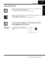
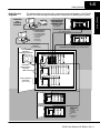
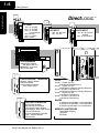
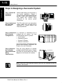
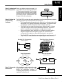
Getting Started
11
In This Chapter. . . .
— Introduction
— DL405 System Components
— Programming Methods
— DirectLOGIC™ Part Numbering System
— Quick Start for PLC Checkout and Programming
— Steps to Designing a Successful System
— Frequently Asked Questions
1--2
Getting Started
Getting Started
Introduction
The Purpose of
this Manual
Thank you for purchasing our DL405
family of products. This manual shows you
how to install, program, and maintain the
equipment. It also helps you understand
how to interface them to other devices in a
control system.
This
manual
contains
important
information for personnel who will install
DL405 PLCs and components, and for the
PLC programmer. If you understand PLC
systems our manuals will provide all the
information you need to get and keep your
system up and running.
Where to Begin
If you already understand PLCs please read Chapter 2, “Installation, Wiring, and
Specifications”, and proceed on to other chapters as needed. Be sure to keep this
manual handy for reference when you have questions. If you are a new DL405
customer, we suggest you read this manual completely so you can understand the
wide variety of features in the DL405 family of products. We believe you will be
pleasantly surprised with how much you can accomplish with our products.
Supplemental
Manuals
If you have purchased operator interfaces or DirectSOFT™, you will need to
supplement this manual with the manuals that are written for these products.
Technical Support
We realize that even though we strive to be the best, we may have arranged our
information in such a way you cannot find what you are looking for. First, check these
resources for help in locating the information:
S
S
S
Table of Contents -- chapter and section listing of contents, in the front
of this manual
Appendices -- reference material for key topics, near the end of this
manual
Index -- alphabetical listing of key words, at the end of this manual
You can also check our online resources for the latest product support information:
S Internet -- Our Web address is
http://www.automationdirect.com
If you still need assistance, please call us at 770--844--4200. Our technical support
group is glad to work with you in answering your questions. They are available
Monday through Friday from 9:00 A.M. to 6:00 P.M. Eastern Standard Time. If you
have a comment or question about any of our products, services, or manuals, please
fill out and return the ‘Suggestions’ card that was shipped with this manual.
DL405 User Manual, 4th Edition, Rev. A
Getting Started
1--3
Conventions Used
When you see the “notepad” icon in the left--hand margin, the paragraph to its
immediate right will be a special note.
The word NOTE: in boldface will mark the beginning of the text.
When you see the “exclamation mark” icon in the left--hand margin, the paragraph to
its immediate right will be a warning. This information could prevent injury, loss of
property, or even death (in extreme cases).
The word WARNING: and text will be in boldface.
Key Topics for
Each Chapter
The beginning of each chapter will list the
key topics that can be found in that
chapter.
1
DL405 User Manual, 4th Edition, Rev. A
Getting Started
When you see the “light bulb” icon in the left--hand margin, the paragraph to its
immediate right will give you a special tip.
The word TIP: in boldface will mark the beginning of the text.
1--4
Getting Started
Getting Started
DL405 System Components
CPUs
The DL405 product family is one of the most versatile and widely accepted PLCs
used for medium control applications. The CPUs are small, yet powerful. Their
modular design and expansion capability blend well with todays fast-moving
industry. The following is a summary of the major DL405 system components.
There are three feature-enhanced CPUs in this product line, the DL430, DL440, and
the DL450. All include a built-in power supply and communication ports. Each CPU
offers a large amount of program memory, a substantial instruction set and
advanced diagnostics. The DL450 features drum timers, floating-point math, built-in
PID loops, and additional communications ports. Details of these CPU features are
covered in Chapter 3, CPU Specifications and Operation.
Bases
Three base sizes are available in the system: 4 slot, 6 slot and 8 slot.
I/O Configuration
The DL430/440 CPUs can support up to 640 I/O between the CPU base and
expansion bases (the DL450 up to 1024 local I/O). A maximum of 512 additional I/O
for the DL430, 1024 for the DL440, or 1536 for the DL450 can be added to the system
in the form of remote I/O bases and slice I/O blocks. Each of these I/O configurations
is explained in Chapter 4, System Design and configuration.
I/O Modules
The DL405 family has some of the most powerful modules in the industry. They
include a complete range of discrete modules which support 24 VDC, 125 VDC,
110/220 VAC and up to 10A relay outputs. Analog modules provide 12-bit resolution
and several selections of input and output signal ranges (including bipolar).
Specialty modules include a 100KHz high-speed input, thermocouple, general
purpose communication, magnetic pulse input, 16 loop PID function and more.
Programming Methods
DirectSOFT
Programming for
Windows™
Handheld
Programmer
There are two programming methods available to the DL405 CPUs, RLL (Relay
Ladder Logic) and RLL PLUS.Stage Programing. Both the DirectSOFT programming
package and the handheld programmer support RLL and Stage.
The DL405 CPUs can be programmed with one of the most advanced programming
packages in the industry ----DirectSOFT 5, Ver. 5 or later. DirectSOFT 5 is a
Windows-based software package that supports many of the Windows features you
already know, such as cut-and-paste between applications, point-and-click editing,
viewing and editing multiple application programs at the same time, browsers, and
newly added Intelligent Box (IBox) Instructions which will help ease your
programming tasks. DirectSOFT 5 universally supports the DirectLOGIC™ CPU
families. This means you can use the same DirectSOFT 5 package to program
DL105, DL205, DL305, DL405 or any new CPUs that we add to our product line.
There is a separate manual for the DirectSOFT 5 programming software.
All DL405 CPUs have a built-in programming port for use with the handheld
programmer (D4--HPP). The HPP can be used to create, modify and debug your
application program. A separate manual for the DL405 HPP is available.
DL405 User Manual, 4th Edition, Rev. A
Getting Started
The diagram below shows the major components and configurations of the DL405
system. The next two pages show specific components for building your system.
COMPUTERS
and
OPERATOR
INTERFACE
PEER-TO-PEER and
MASTER/SLAVE
COMMUNICATIONS
Printer
305
System Migration
or Expansion
DirectNET/Modbusr Communication
(max. 3300ft/1000m)
DirectNET/Modbusr
Communication
(max. 3300ft/1000m)
1. ONLINE/OFFLINE
Programming
2. Reporting
3. Monitoring
4. Debugging
405
General RS232C/
RS422 Port
(max. 3300ft1000m)
DirectNET Communication (max. 3300ft/1000m)
Local Operator
Interface or
handheld programmer
405
RM
Connects to
DL405 Programming Port
DCM MB DCM
MSTR
EX
(Max. 3.3ft/1m)
EX
Up to 3 expansion
bases total
(only 2 shown)
RS
REMOTE I/O
RS
1. Flexible
Placement of I/O
2. Reduced
Installation
Costs
3. Versatile I/O
Offering
DL405 User Manual, 4th Edition, Rev. A
Getting Started
DL405 System
Diagrams
1--5
Getting Started
1--6
Getting Started
Direct LOGIC™
DC INPUT
8pt 24--48 VDC
16pt 12--24 VDC
16pt 12--24 VDC
(1ms response)
32pt 24 VDC
32pt 5--12 VDC
64pt 24VDC
AC INPUT
8pt 110--200 VAC
16pt 110 VAC
AC/DC INPUT
8pt 90--150 VAC/DC
Isolated
16pt 12--24 VAC/DC
PROGRAMMING
Handheld Programmer
with Built-in RLL PLUS
DirectSOFT 5 Programming for Windows
COPROCESSORt MODULES
RS232C / RS422 / RS485
Telephone Modem
Program Memory Ranges
from 128K to 512K
SPECIALTY MODULES
8/16pt Input Simulator
8pt Interrupt Input Module
High Speed Counter Module
8 pt. Magnetic Pulse Input Module
16 Loop PID Module
4 Loop Temperature Controller
SDSt Interface Module
Filler Module
DL405 User Manual, 4th Edition, Rev. A
CPUs
DL430 -- 110/220 VAC P/S,
6.5K Built-in EPROM Memory
DL440 -- 110/220 VAC P/S,
22.5K Memory (Memory Cartridge Required)
DL440 -- 24 VDC or 125 VDC P/S,
22.5K Memory (Memory Cartridge Required)
DL450 -- 110/220 VAC P/S
7.5K Built-in Flash Memory
DL450 -- 24 VDC or 125 VDC P/S
7.5K Built-in Flash Memory
BASES
4 Slot Bases (expandable or nonexpandable)
6 Slot Bases (expandable or nonexpandable)
8 Slot Base (expandable or nonexpandable)
MEMORY CARTRIDGES
CMOS RAM w/battery
UVPROM
EEPROM
Getting Started
1--7
RELAY OUTPUT
DC OUTPUT
8pt
8pt
16pt
16pt
32pt
32pt
64pt
12--24 VDC
24--250 VDC
5--24 VDC
12--24 VDC
5--24 VDC
12--24 VDC
5--24VDC
8pt
8pt
8pt
16pt
AC OUTPUT
8pt 18--220 VAC
16pt 18--220 VAC
10A/pt
5A/pt
2A/pt
1A/pt
I/O SYSTEMS
Expansion Bases
Local Base Expansion Unit
110/220 VAC P/S
Local Base Expansion Unit
24 VDC P/S
Local Base Expansion Unit
125 VDC P/S
Remote I/O
Remote I/O Master Module
Remote I/O Slave Unit 110--220 VAC
Remote I/O Slave Unit 24 VDC
DL450 CPU
Direct remote I/O link on Port 3
NETWORKING
Ethernet Communication Module
Data Communication Module
DirectNET Network/Modbusr
DL450 CPU (Ports 1 and 3)
DirectNET Network/Modbusr
Modbusr Master Module
Modbusr Slave Module
TIWAYt Network Interface Module
Shared Data Network Module
ANALOG
4CH
8CH
16CH
4CH
8CH
16CH
8CH
8CH
Input
Input
Input
Output
Output
Output
Thermocouple Input
RTD Input
DL405 User Manual, 4th Edition, Rev. A
Getting Started
DL405 Family
1--8
Getting Started
Getting Started
DirectLOGIC™ Part Numbering System
A DL405 PLC control system may be comprised of many products from the DL405 family. The part
numbering system below shows how the part numbering systems work for each product category. Part
numbers for accessory items such as cables, batteries, memory cartridges etc. are typically an abbreviation
of the description for the item.
CPUs and Micro PLCs
Specialty CPUs
Product family
D1/F1
D2/F2
D4--
440DC
--1
D3--
05B
D4--
16
N
D
2
D3--
16
N
D
2
D3/F3
D4/F4
Class of CPU / Abbreviation
230...,330...,430...
Denotes a differentiation between
similar modules
--1, --2, --3, --4
Bases
Product family
D2/F2
DC
D3/F3
D4/F4
Number of slots
##B
Type of Base
DC or empty
Discrete I/O
DL205 Product family
y
D2/F2
DL305 Product family
D3/F3
DL405 Product family
D4/F4
Number of points
04/08/12/16/32/64
Input
p
N
Output
p
T
Combination
C
AC
A
DC
D
Either
E
Relay
Current Sinking
g
R
1
Current Sourcing
g
2
Current Sinking/Sourcing
3
High
g Current
H
Isolation
S
Fast I/O
Denotes a differentiation between
Similar modules
F
--1, --2, --3, --4
DL405 User Manual, 4th Edition, Rev. A
F
--1
1--9
Getting Started
DirectLOGIC™ Part Numbering System
DL205 Product family
y
D2/F2
DL305 Product family
D3/F3
DL405 Product family
D4/F4
Number of channels
02/04/08/16
Input
p ((Analog
g to Digital)
g )
AD
Output
p ((Digital
g
to Analog)
g)
DA
Combination
Isolated
xADxDA
S
Denotes a differentiation between
Similar modules
--1, --2, --3, --4
Communication and Networking,
Special I/O and Devices
Programming
DL205 Product family
D2/F2
DL305 Product family
D3/F3
DL405 Product family
D4/F4
Name Abbreviation
see example
CoProcessors and ASCII BASIC Modules
DL205 Product family
y
D2/F2
DL305 Product family
D3/F3
DL405 Product family
D4/F4
CoProcessor
CP
ASCII BASIC
AB
64K memoryy
64
128K memoryy
128
512K memory
512
Radio modem
R
Telephone modem
T
F3--
04
AD
S
Getting Started
Analog I/O
--1
Alternate example of Analog I/O
using abbreviations
F3--
08
THM
--n
note: --n indicates thermocouple type
such as: J, K, T, R, S or E
D4--
DCM
D3--
HSC
HSC (High Speed Counter)
D3--
HPP
HPP (RLL PLUS Handheld Programmer)
F4--
CP
DCM (Data Communication Module)
128
-- R
DL405 User Manual, 4th Edition, Rev. A
1--10
Getting Started
Getting Started
Quick Start for PLC Checkout and Programming
If you have experience with PLCs, or if you just want to setup a quick example, this
section is for you! This example is not intended to tell you everything you need to
start-up your system. It is only intended to give you a general picture of what you will
need to do to get your system powered-up.
Step 1: Unpack the Unpack the DL405 equipment and verify you have the parts necessary to build this
DL405 Equipment demonstration system. The minimum parts you will need are:
S Base
S CPU (with a memory cartridge if you are using a DL440 or DL450)
S D4--16ND2 DC input module or a D4--16SIM input simulator module
S D4--16TR Relay output module
S Power cord
S Hook up wire
S A 24 VDC toggle switch (if not using the input simulator module)
S A screwdriver, regular or Philips type
You will need at least one of the following programming options:
S DirectSOFT Programming Software, DirectSOFT Manual, and a
programming cable (connects the CPU to a personal computer), or
S D4--HPP Handheld Programmer (programming cable is optional), and
the Handheld Programmer Manual
DL405 User Manual, 4th Edition, Rev. A
Getting Started
Insert the CPU and I/O into the base. The CPU must go into the far left side of the
base in the position marked “CPU/Power Supply”. When inserting components into
the base, tilt the component slightly forward sliding the tab on the bottom of the
component into the slot in the base. Push the top of the component into the base until
it is seated firmly, then tighten the securing screw at the top of the module/unit.
Placement of discrete, analog and relay modules are not critical and may go in any
slot in any base however for this example install the output module in the slot next to
the CPU (slot 0) and the input module in the next slot (slot 1). Limiting factors for
other types of modules are discussed in Chapter 4, Bases, Expansion Units and I/O
Configuration. You must also make sure you do not exceed the power budget for
each base in your system configuration. Power budgeting is discussed in Chapter 4,
System Design and Configuration.
S
S
S
S
Step 3: Remove
Terminal Strip
Access Cover
Each unit has a plastic tab at the
bottom and a screw at the top.
With the unit tilted slightly
forward, hook the module’s plastic
tab on the base.
Gently push the top of the unit
back until it is firmly installed in
the base.
Secure the unit to the base by
tightening the top screw.
Remove the terminal strip cover. It has a
small retention snap on the left edge. Push
in and up then pull the cover off.
Push in
and lift off
Step 4: Install
Memory Cartridge
If you are using a DL440 CPU (optional on
DL450) you need to install the memory
cartridge in the slot to the right of the
battery. Make sure it is firmly seated. To
find out more about memory cartridges
see Chapter 3.
Memory
Cartridge
Step 5: Select
Operating Power
Range
If you are using 110VAC install the voltage select jumper on the bottom two
terminals. If you are using 220VAC power, do not install the jumper. You can find a
detailed explanation of the terminal block on both the CPU and expansion units in
Chapter 2, Installation, Wiring, and Specifications.
DL405 User Manual, 4th Edition, Rev. A
Getting Started
Step 2: Install the
CPU and I/O
Modules
1--11
Getting Started
1--12
Getting Started
WARNING: Damage will occur to the power supply if 220 VAC is connected to
the terminal connections with the 110 VAC shunt in place.
Run Relay
If using D4--0X--1 type bases,
install this shunt to connect
grounds, for proper noise
immunity.
24V
Auxiliary
Power
Logic
Ground
Chassis
Ground
Install shunt to select
110 VAC range, leave shunt
off to select 220 VAC range.
AC Power
110/220
Voltage
Select
Step 6: Add I/O
Simulation
To finish this quick-start exercise or study other examples in this manual, you’ll need
to install an input simulator module (or wire an input switch as shown below), and
add an output module. Using an input simulator is the quickest way to get physical
inputs for checking out the system or a new program. To monitor output status, any
discrete output module will do.
--
Toggle switch
Output
Module
Input
Module
Wire the switches or other field devices prior to applying power to the system to
ensure a point is not accidentally turned on during the wiring operation. Wire the
input module (X0) to the toggle switch and 24VDC auxiliary power supply on the
CPU terminal strip as shown below for the 16ND2 input module. Chapter 2,
Installation, Wiring, and Specifications provides a list of I/O wiring guidelines.
DL405 User Manual, 4th Edition, Rev. A
1--13
Getting Started
Connect the wires as shown. Observe all
precautions stated earlier in this manual.
For details on wiring, see Chapter 2,
Installation, Wiring, and Specifications.
When the wiring is complete, replace the
CPU and module covers. Do not apply
power at this time.
Getting Started
Step 7: Connect
the Power Wiring
Ground
Line
Neutral
Step 8: Connect
the Handheld
Programmer
Remove the connector cover at the top
right of the CPU. Join the Handheld
programmer’s 15 pin D type connector
(located on the back) to the connector you
just uncovered on the CPU. Finger tighten
the securing screws on the top and bottom
of the Handheld programmer.
Step 9: Switch On
the System Power
Apply power to the system and ensure the PWR indicator on the CPU is on. If not,
remove power from the system and check all wiring and refer to the troubleshooting
section in Chapter 9 for assistance.
Step 10: Enter the
Program
Turn the key switch on the CPU to the STOP position and then back to the TERM
position. This puts the CPU in the program mode and allows access to the CPU
program. The PGM indicator should be illuminated on the HPP. Enter the following
keystrokes on the HPP:
Securing screws
NOTE: It is not necessary for you to configure the I/O for this system since the DL430
CPUs automatically configure I/O and the DL440 and DL450 CPUs default to
automatic I/O configuration.
CLR
CLR
AUX
2
4
CLR
$(AD)
0
STR
X(IN)
0
OUT
Y(OUT)
0
X0
Y0
NXT
END
END
After entering the simple example program turn the key switch from the TERM
position to the RUN position and back to TERM. The RUN indicator on the CPU will
come on indicating the CPU has entered the run mode. If not repeat Step 10 insuring
the program is entered properly or refer to the troubleshooting guide in chapter 9.
During Run mode operation, the output status indicator 0 on the output module
should reflect the switch status. When the switch is on the output should be on.
DL405 User Manual, 4th Edition, Rev. A
1--14
Getting Started
Getting Started
Steps to Designing a Successful System
Step 1: Review the
Installation
Guidelines
Always make safety your first priority in
any system application. Chapter 2
provides several guidelines that will help
provide a safer, more reliable system.
This chapter also includes wiring
guidelines for the various system
components.
Step 2: Understand
the CPU Setup
Procedures
The CPU is the heart of your automation
system. Make sure you take time to
understand its various features and
setup requirements.
Step 3: Understand It is important to understand how to
configure the I/O system. You have
the I/O System
several different types of systems:
Configurations
S Local System
S Expansion System
S Remote I/O System
S Network connections
It is also important to understand how the
system Power Budget is calculated. See
Chapter 4 for more information.
Step 4: Determine
the I/O Module
Specifications and
Wiring
Characteristics
Emergency
Stop
16pt
Input
8pt
Input
32pt
Input
X0
X20
X30
16pt
Output
Y0
8pt
Output
16pt
Output
Y20
Y30
--
--
--
--
--
--
X17
X27
X67
Y17
Y27
Y47
There are many different I/O modules
available with the DL405 system. Chapter
2 provides the specifications and wiring
diagrams for the discrete I/O modules.
32 pt. Module
OR
Ribbon connector
NOTE: Analog and other specialty modules have their own manuals and are not
included in this manual.
DL405 User Manual, 4th Edition, Rev. A
1--15
Getting Started
Step 5: Understand Before you begin to enter a program, it is
the CPU Operation very helpful to understand how the DL405
CPU processes information. This involves
not only program execution steps, but also
involves the various modes of operation
and memory layout characteristics. See
Chapter 3 for more information.
Getting Started
Power up
Initialize hardware
Check I/O module
config. and verify
Step 6: Review the The DL405 PLC provides four main approaches to solving the application program,
including the PID loop task depicted in the next figure.
Programming
Concepts
S RLL diagram-style programming is the best tool for solving boolean logic
and general CPU register/accumulator manipulation. It includes dozens
of instructions, which will augment drums, stages, and loops.
S The DL450 has four timer/event drum types, each with up to 16 steps
They offer both time and/or event-based step transitions. Drums are
best for a repetitive process based on a single series of steps.
S Stage programming (also called RLL Plus) is based on state-transition
diagrams. Stages divide the ladder program into sections which
correspond to the states in a flow chart you draw for your process.
S The DL450 PID Loop Operation uses setup tables to configure up to 16
loops. Features include alarms, SP ramp/soak generation, and more.
Timer/Event Drum Sequencer
(see Chapter 6)
Standard RLL Programming
(see Chapter 5)
X0
LDD
V1076
CMPD
K309482
SP62
Y0
OUT
Stage Programming
(see Chapter 7)
Push--UP
PID Loop Operation
(see Chapter 8)
RAISE
SP
DOWN
LIGHT
UP
+
Σ
PID
Process
-PV
LOWER
Push-DOWN
Step 7: Choose the After installation and studying the main
programming concepts, you can begin
Instructions
writing the application program or
configuring loop operation. You’ll discover
a powerful instruction set!
TMR
K30
T1
CNT
K10
CT3
DL405 User Manual, 4th Edition, Rev. A
Getting Started
1--16
Getting Started
Step 8: Understand
the Maintenance
and
Troubleshooting
Procedures
Sometimes equipment failures occur
when we least expect it. Switches fail,
loads short and need replacement, etc.
Often, the majority of the troubleshooting
time is spent in locating the problem. The
DL405 system has many built-in features
such as error codes that can help you
quickly identify problems. See Chapter 9
for diagnostics and troubleshooting tips.
Frequently Asked Questions
Q. How do I reset my DL405 CPU back to factory defaults
A. Resetting the processor to factory defaults is a two step process. First clear the
processor memory using DirectSOFT PLC>CLEAR PLC MEMORY. Next initialize
the scratchpad PLC>SETUP>INITIALIZE SCRATCHPAD. Be aware that
initializing the scratchpad will reset the system V--memory to defaults. System
V--memory contains parameters such as retentive ranges, communications port
settings, etc.
Q. How often should the CPU backup battery be changed?
A. All of the 405 CPUs have an LED indicator that will flash when the battery voltage
is getting low. The typical battery life is 5 years.
Q. Where can I obtain the most current firmware for the DL450?
A. In the tech support section of www.automationdirect.com. The firmware and
instructions on how to update the CPU are available.
Q. Do the DL405 PLCs have ethernet capability?
A. Yes, the H4--ECOM module is needed to support ethernet.
Q. Can the DL405 use the Modbus protocol?
A. The DL450 supports Modbus on port 1 or 3 as a master or slave. The DL--430/440
can support Modbus using the F4--MAS--MB master or F4--SLV--MB slave module.
Q. Can I have more than 16 PID loops on a system using the DL450?
A. Yes. You can still use the 16-loop PID module in the base, plus the DL450’s loops.
Q. What are the networking capabilities of the DL450?
A. The DL430/DL440 CPUs can serve as DirectNET slaves. The DL450 has two
network ports, which can serve as DirectNET masters or slaves, or MODBUS
masters or slaves.
Q. Are more FAQs available for the DL405 and other products?
A. Yes, visit www.automationdirect.com for more FAQs and other technical
information.
DL405 User Manual, 4th Edition, Rev. A